EP4332911A1 - Configuration automatique de réglages de caméra à l'aide d'un radar - Google Patents
Configuration automatique de réglages de caméra à l'aide d'un radar Download PDFInfo
- Publication number
- EP4332911A1 EP4332911A1 EP23170916.3A EP23170916A EP4332911A1 EP 4332911 A1 EP4332911 A1 EP 4332911A1 EP 23170916 A EP23170916 A EP 23170916A EP 4332911 A1 EP4332911 A1 EP 4332911A1
- Authority
- EP
- European Patent Office
- Prior art keywords
- occupancy
- camera
- count
- interest
- sensors
- Prior art date
- Legal status (The legal status is an assumption and is not a legal conclusion. Google has not performed a legal analysis and makes no representation as to the accuracy of the status listed.)
- Withdrawn
Links
Images





Classifications
-
- G—PHYSICS
- G01—MEASURING; TESTING
- G01S—RADIO DIRECTION-FINDING; RADIO NAVIGATION; DETERMINING DISTANCE OR VELOCITY BY USE OF RADIO WAVES; LOCATING OR PRESENCE-DETECTING BY USE OF THE REFLECTION OR RERADIATION OF RADIO WAVES; ANALOGOUS ARRANGEMENTS USING OTHER WAVES
- G01S13/00—Systems using the reflection or reradiation of radio waves, e.g. radar systems; Analogous systems using reflection or reradiation of waves whose nature or wavelength is irrelevant or unspecified
- G01S13/02—Systems using reflection of radio waves, e.g. primary radar systems; Analogous systems
- G01S13/06—Systems determining position data of a target
-
- G—PHYSICS
- G06—COMPUTING OR CALCULATING; COUNTING
- G06V—IMAGE OR VIDEO RECOGNITION OR UNDERSTANDING
- G06V20/00—Scenes; Scene-specific elements
- G06V20/50—Context or environment of the image
- G06V20/52—Surveillance or monitoring of activities, e.g. for recognising suspicious objects
-
- G—PHYSICS
- G06—COMPUTING OR CALCULATING; COUNTING
- G06F—ELECTRIC DIGITAL DATA PROCESSING
- G06F17/00—Digital computing or data processing equipment or methods, specially adapted for specific functions
- G06F17/10—Complex mathematical operations
- G06F17/11—Complex mathematical operations for solving equations, e.g. nonlinear equations, general mathematical optimization problems
- G06F17/12—Simultaneous equations, e.g. systems of linear equations
-
- G—PHYSICS
- G06—COMPUTING OR CALCULATING; COUNTING
- G06T—IMAGE DATA PROCESSING OR GENERATION, IN GENERAL
- G06T7/00—Image analysis
- G06T7/70—Determining position or orientation of objects or cameras
- G06T7/73—Determining position or orientation of objects or cameras using feature-based methods
-
- G—PHYSICS
- G06—COMPUTING OR CALCULATING; COUNTING
- G06V—IMAGE OR VIDEO RECOGNITION OR UNDERSTANDING
- G06V10/00—Arrangements for image or video recognition or understanding
- G06V10/10—Image acquisition
- G06V10/12—Details of acquisition arrangements; Constructional details thereof
-
- G—PHYSICS
- G06—COMPUTING OR CALCULATING; COUNTING
- G06V—IMAGE OR VIDEO RECOGNITION OR UNDERSTANDING
- G06V10/00—Arrangements for image or video recognition or understanding
- G06V10/20—Image preprocessing
- G06V10/24—Aligning, centring, orientation detection or correction of the image
-
- G—PHYSICS
- G06—COMPUTING OR CALCULATING; COUNTING
- G06V—IMAGE OR VIDEO RECOGNITION OR UNDERSTANDING
- G06V20/00—Scenes; Scene-specific elements
- G06V20/50—Context or environment of the image
- G06V20/52—Surveillance or monitoring of activities, e.g. for recognising suspicious objects
- G06V20/54—Surveillance or monitoring of activities, e.g. for recognising suspicious objects of traffic, e.g. cars on the road, trains or boats
-
- H—ELECTRICITY
- H04—ELECTRIC COMMUNICATION TECHNIQUE
- H04N—PICTORIAL COMMUNICATION, e.g. TELEVISION
- H04N23/00—Cameras or camera modules comprising electronic image sensors; Control thereof
- H04N23/60—Control of cameras or camera modules
- H04N23/61—Control of cameras or camera modules based on recognised objects
-
- H—ELECTRICITY
- H04—ELECTRIC COMMUNICATION TECHNIQUE
- H04N—PICTORIAL COMMUNICATION, e.g. TELEVISION
- H04N23/00—Cameras or camera modules comprising electronic image sensors; Control thereof
- H04N23/60—Control of cameras or camera modules
- H04N23/69—Control of means for changing angle of the field of view, e.g. optical zoom objectives or electronic zooming
-
- H—ELECTRICITY
- H04—ELECTRIC COMMUNICATION TECHNIQUE
- H04N—PICTORIAL COMMUNICATION, e.g. TELEVISION
- H04N23/00—Cameras or camera modules comprising electronic image sensors; Control thereof
- H04N23/60—Control of cameras or camera modules
- H04N23/695—Control of camera direction for changing a field of view, e.g. pan, tilt or based on tracking of objects
-
- H—ELECTRICITY
- H04—ELECTRIC COMMUNICATION TECHNIQUE
- H04N—PICTORIAL COMMUNICATION, e.g. TELEVISION
- H04N23/00—Cameras or camera modules comprising electronic image sensors; Control thereof
- H04N23/80—Camera processing pipelines; Components thereof
Definitions
- the present disclosure relates generally to camera-based monitoring systems, and more particularly to methods and system for automatically configuring camera settings of such camera-based monitoring system.
- Camera-based monitoring systems are often used to monitor a monitoring region, and to identify certain objects and/or certain events that occur in the monitored region.
- a surveillance system often includes one or more cameras configured to monitor a surveilled region. The surveillance system may identify certain objects and/or certain events that occur in the surveilled region.
- a traffic monitoring system may monitor vehicle traffic along a roadway or the like.
- a License Plate Recognition (LPR) algorithm is used to processes images captured by one or more cameras of the traffic monitoring system to identify license plates of vehicles as they travel along the roadway.
- LPR License Plate Recognition
- the quality of the images captured the cameras can be important to help identify certain objects and/or certain events in the monitored region.
- the quality of the images is often dependent upon the interplay between the camera settings, such as shutter speed, shutter aperture, focus, pan, tilt, and zoom, the conditions in the monitored region such as available light, and characteristics of the objects such as object type, object distance, object size and object speed.
- an illustrative system may include a camera having a field of view, a radar sensor having a field of view that at least partially overlaps the field of view of the camera, and a controller operatively coupled to the camera and the radar sensor.
- the controller is configured to receive one or more signals from the radar sensor, identify an object of interest moving toward the camera based at least in part on the one or more signals from the radar sensor, determine a speed of travel of the object of interest based at least in part on the one or more signals from the radar sensor, determine a projected track of the object of interest, and determine a projected image capture window within the field of view of the camera at which the object of interest is projected to arrive based at least in part on the determined speed of travel of the object of interest and the projected track of the object of interest.
- the projected image capture window corresponds to less than all of the field of view of the camera.
- the controller sends one or more camera setting commands to the camera, including one or more camera setting commands that set one or more of: a shutter speed camera setting based at least in part on the speed of travel of the object of interest, a focus camera setting to focus the camera on the projected image capture window, a zoom camera setting to zoom the camera to the projected image capture window, a pan camera setting to pan the camera to the projected image capture window, and a tilt camera setting to tilt the camera to the projected image capture window.
- the controller may further send an image capture command to the camera to cause the camera to capture an image of the projected image capture window.
- the controller may localize a region of the projected image capture window that corresponds to part or all of the object of interest (e.g.
- the controller may change the encoder quantization value, which influences the degree of compression of an image or region of an image, thus affecting the quality of the image in the region.
- a system that includes a camera having an operational range, a radar sensor having an operational range, wherein the operational range of the radar sensor is greater than the operational range of the camera, and a controller operatively coupled to the camera and the radar sensor.
- the controller is configured to identify an object of interest within the operational range of the radar sensor using an output from the radar sensor, determine one or more motion parameters of the object of interest, set one or more camera settings for the camera based on the one or more motion parameters of the object of interest, and after setting the one or more camera settings for the camera, cause the camera to capture in an image of the object of interest.
- a method for operating a camera that includes identifying an object of interest using a radar sensor, wherein the object of interest is represented as a point cloud, tracking a position of the object of interest, and determining a projected position of the object of interest, wherein the projected position is within a field of view of a camera.
- the method further includes determining a projected image capture window that corresponds to less than all of the field of view of the camera, the projected image capture window corresponds to the projected position of the object of interest, setting one or more camera settings of the camera for capturing an image of the object of interest in the projected image capture window, and capturing an image of the object of interest when at least part of the object of interest is at the projected position and in the projected image capture window.
- references in the specification to "an embodiment”, “some embodiments”, “illustrative embodiment”, “other embodiments”, etc., indicate that the embodiment described may include a particular feature, structure, or characteristic, but every embodiment may not necessarily include the particular feature, structure, or characteristic. Moreover, such phrases are not necessarily referring to the same embodiment. Further, when a particular feature, structure, or characteristic is described in connection with an embodiment, it is contemplated that the feature, structure, or characteristic may be applied to other embodiments whether or not explicitly described unless clearly stated to the contrary.
- FIG. 1 is a schematic block diagram of an illustrative camera-based monitoring system 10.
- the illustrative camera-based monitoring system 10 may include a video or still camera 12. While one camera 12 is shown, it will be appreciated that in some cases the system 10 may have two cameras, three cameras, four cameras, six cameras, eight cameras, or any other suitable number of cameras 12, depending on the application.
- the camera 12 may include an image sensor 13, which may determine a Field of View (FOV) and an operational range, which together define at least in part the operational area that the camera 12 can be used to reliably detect and/or identifying objects of interest for the particular application at hand.
- FOV Field of View
- the FOV of the camera 12 may define a horizontal FOV for the camera 12, and in some cases, a distance in which the camera 12 can reliably detect and/or identify objects of interest for the particular application at hand. In some cases, an operational range may separately define a distance in which the camera 12 can reliably detect and/or identifying objects of interest for the particular application at hand.
- the camera 12 may be configured to capture a video stream or a still image of the FOV. In some cases, the camera 12 may be a pan, tilt, zoom (PTZ) camera, as indicated by PTZ 11, but this is not required. For fixed cameras, the corresponding FOV is also fixed. For adjustable cameras, such as pan, tilt, zoom (PTZ) cameras, the corresponding FOV is adjustable.
- the camera 12 may have a network address, which identifies a specific addressable location for that camera 12 on a network.
- the network may be a wired network, and in some cases, the network may be a wireless network communicating using any of a variety of different wireless communication protocols.
- the illustrative system 10 further includes a radar sensor 14.
- the radar sensor 14 may be contained within the housing of the camera 12, as indicated by the dashed lines, but this is not required. In some cases, the radar sensor 14 is separate from the camera 12.
- the radar sensor 14 may include a millimeter wave (mmWave) antenna 15 that may determine a Field of View (FOV) and an operational range, which together define at least in part the operational area that the radar sensor 14 can be used to reliably detect and/or identifying objects of interest for the particular application at hand.
- the FOV of the radar sensor 14 may define a horizontal FOV for the radar sensor 14, and in some cases, may define a distance in which the radar sensor 14 may reliably detect and/or identify objects of interest for the particular application at hand.
- the radar sensor 14 may be have an operational range of 100-250 meters for detecting vehicles along a roadway. In some cases, the radar sensor 14 may have an operational range of 200-250 meters, or an operational range of 100-180 meters, or an operational range of 100-150 meters. These are just examples. In some cases, as described herein, the FOV of the radar sensor 14 at least partially overlaps the FOV of the camera 12. In some cases, the operational range of the FOV of the radar sensor 14 is greater than the operational range of the FOV of the camera 12 for detecting and/or identifying objects when applied to a particular application at hand. In some cases, the FOV of the radar sensor 14 may include a horizontal FOV that corresponds generally to a horizontal FOV of the camera 12 FOV, but this is not required.
- the radar sensor 14 may utilize a radio wave transmitted from the radar sensor 14 and receive a reflection from an object of interest within the FOV.
- the radar sensor 14 may be used to detect the object of interest, and may also detect an angular position and distance of the object of interest relative to the radar sensor 14.
- the radar sensor may also be used to detect a speed of travel for the object of interest. In some cases, the radar sensor 14 may be used to track the object of interest over time.
- Some example radar sensors may include Texas Instruments TM FMCW radar, imaging radar, light detection and ranging (Lidar), micro-doppler signature radar, or any other suitable radar sensors.
- the illustrative system 10 of Figure 1 also includes a remote site 18 that may be operably coupled with the network (not shown).
- the camera 12 and the radar sensor 14 can communicate with the remote site 18 over the network.
- the remote site 18 may be, for example, a remote computer, a remote cloud-based server, a remote mobile device such as a mobile phone or tablet, or any other suable remote computing device.
- the remote site 18 may include a display that can be used to display a video image so a human observer can view the image.
- the illustrative system 10 of Figure 1 may include a controller 16.
- the controller 16 may be operatively coupled to the camera 12 and the radar sensor 14.
- the controller 16 may be configured to, for example, receive one or more signals from the radar sensor 14 and identify an object of interest, which may be moving toward the radar sensor and the camera 12. Based upon a signal received from the radar sensor 14, the controller 16 may identify one or more objects of interest in the FOV of the radar sensor.
- the controller 16 may also determine an angular position and distance of each of the identified objects of interest relative to the radar sensor 14, and a speed of travel of each of the identified objects of interest.
- the controller 16 may also determine one or more motion parameters of each of the identified objects of interest.
- the motion parameters may include, for example, a speed of travel of each of the identified objects of interest, a direction of travel of each of the identified objects of interest, a past track of each of the identified objects of interest, and/or a projected future track of each of the identified objects of interest.
- the controller 16 may in some cases determine a radar signature of each of the identified objects of interest.
- the radar signature may be based on, for example, radar signals that indicate parts of an object moving faster/slower than other parts of the same object (e.g. hands moving at different speeds from the body of a person, wheels moving/turning at different speeds than the body of the car), radar signals that indicate a reflectivity of all or parts of an object, radar signals that indicate the size of the object, and/or any other suitable characteristic of the radar signal.
- the radar signatures may be used to help classify objects into one or more object classifications.
- the radar signatures may be used to help distinguish between a car and a truck, between a person and a car, between a person riding a bike and a car.
- Other radar and/or image parameters may be used in conjunction with the radar signatures to help classify the objects.
- object speed may be used to help distinguish between a person walking and a car.
- the controller 16 may be configured to classify the objects of interest into one of a plurality of classifications.
- the plurality of classifications may include a vehicle (e.g., a car, a van, a truck, a semi-truck, a motorcycle, a moped, and the like), a bicycle, a person, or the like.
- more than one object of interest may be identified. For example, two vehicles may be identified, or a bicycle and a vehicle may be identified, or a person walking on the side of a road and a vehicle may be identified. These are just examples.
- the controller 16 may be configured to determine a projected future position of the object of interest based, at least in part, on the projected track of the object of interest.
- the controller 16 may determine a projected image capture window within the FOV of the camera 12 at which the object of interest is projected to arrive based, at least in part, on the determined speed of travel of the object of interest and the projected track of the object of interest.
- the projected image capture window may correspond to less than all of the FOV of the camera 12, but this is not required.
- the controller 16 may include a memory 17.
- the memory 17 may be configured to store relative FOV information of the camera 12 relative to the FOV of the radar sensor 14.
- the controller 16 may further include one or more camera settings 19.
- the one or more camera settings 19 may include, for example, one or more of a shutter speed camera setting, an aperture camera setting, a focus camera setting, a zoom camera setting, a pan camera setting, and a tilt camera setting.
- the controller 16 may be configured to send one or more camera setting 19 commands to the camera 12, and after the camera settings 19 have been set for the camera 12, the controller 16 may send an image capture command to the camera 12 to cause the camera 12 to capture an image of the projected image capture window.
- the controller 16 may be configured to cause the camera 12 to capture an image of the object of interest when the object of interest reaches the projected future position.
- the controller 16 may further localize the object of interest or part of the object of interest (e.g. license plate), and may set image encoder parameters to achieve a higher-quality image for that region of the image.
- the controller 16 may adjust an encoder quantization value, which may impact a degree of compression of the image or part of the image of the projected image capture window, thereby creating a higher-quality image, but this is not required.
- the text/characters in the license plate can be improved through well-known image enhancement techniques, when desired.
- the camera settings 19 may be determined using one or more motion parameters of the detected objects of interest, one or more of the radar signatures of the detected objects of interest and/or one or more classifications of the detected objects of interest.
- the camera settings 19 may be based, at least in part, on the speed of travel of an object of interest detected in the FOV of the camera 12.
- the shutter speed camera setting may have a linear correlation with the speed of travel of the object of interest. For example, the faster the speed of travel, the faster the shutter speed, which creates a shorter exposure of the camera 12 thereby reducing blur in the resulting image.
- the aperture camera setting may be increased.
- the aperture camera setting may be based, at least in part, on the shutter speed camera setting and ambient lighting conditions. For example, when the shutter speed camera setting is set to a faster speed, the aperture may be set to a wider aperture to allow more light to hit the image sensor within the camera 12. In some cases, adjust the aperture setting may be accomplished by adjusting an exposure level setting of image sensor of the camera 12, rather than changing a physical aperture size of the camera 12.
- the shutter speed camera setting and the aperture camera setting may be based, at least in part, on the time of day, the current weather conditions and/or current lighting conditions. For example, when there is more daylight (e.g., on a bright, sunny day at noon) the shutter speed may be faster and the aperture may be narrower than at a time of day with less light (e.g., at midnight when it is dark, or on a cloudy day). These are just examples.
- the controller 16 may be configured to set a focus camera setting to focus the camera 12 on the projected image capture window. In other cases, an autofocus feature of the camera 12 may be used to focus the camera on the object as the object reaches the projected image capture window. In some cases, the controller 16 may set a zoom camera setting to zoom the camera 12 to the projected image capture window. In some cases, the camera 12 may set a pan camera setting and the tilt camera setting to pan and tilt to the camera to capture the projected image capture window.
- the object of interest may be a vehicle traveling along a roadway
- the projected image capture window may include a license plate region of the vehicle when the vehicle reaches the projected image capture window.
- the controller 16 may send a camera setting command to the camera 12 to pan and tilt the camera 12 toward the projected image capture window before the vehicle reaches the projected image capture window, focus the camera 12 on the projected image capture window and zoom the camera 12 on the projected image capture window to enhance the image quality at or around the license plate of the vehicle.
- the controller 16 may send an image capture command to the camera 12 to capture an image of the license plate of the vehicle when the vehicle reaches the projected image capture window.
- the controller 16 may be configured to initially identify an object of interest as a point cloud cluster from the signals received from the radar sensor 14.
- the position e.g. an angular position and distance
- the position of the object of interest may be determined from the point cloud cluster.
- the position of the object of interest may be expressed on a cartesian coordinate ground plane, wherein the position of the object of interest is viewed from an overhead perspective.
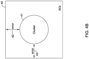
- the controller 16 may be configured to determine a bounding box for the object of interest based, at least in part, on the point cloud. In such cases, as shown in Figure 4B , the bounding box may be configured to include the point cloud cluster for the object of interest and may include a margin of error in both the X and Y axis to identify a Region of Interest (ROI).
- ROI Region of Interest
- the margin of error that is applied may be reduced the closer the object of interest gets to the camera 12.
- a bounding box may be configured for each object of interest.
- the bounding boxes (or ROI) may be transformed from the cartesian coordinate ground plane to the image plane (e.g. pixels) of the camera 12 using a suitable transformation matrix.
- the controller 16 may be configured to determine the projected image capture window based, at least in part, on the bounding box (or ROI) for the object of interest and the projected future track of the objects of interest.
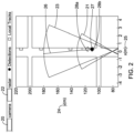
- FIG 2 is a schematic diagram illustrating a field of view (FOV) 21 of a camera 20 (e.g., camera 12) and a field of view (FOV) 23 of a radar sensor 22 (e.g., radar sensor 14).
- FOV 21 of the camera 20 and the FOV 23 of the radar sensor 22 may define at least in part what the camera 20 and the radar sensor 22 can see.
- FOV 23 of the radar sensor 22 at least partially overlaps the FOV 21 of the camera 20.
- the FOV 23 of the radar sensor 22 is greater than the FOV 21 of the camera 20.
- the FOV 23 of the radar sensor 22 may include a horizontal FOV that corresponds to a horizontal FOV of the camera 20 FOV 21.
- the FOV 23 of the radar sensor 22 may extend to around 180 meters, as can be seen on the Y-axis 24. This may overlap with the FOV 21 of the camera 20 which may extend to around 130 meters. These are just examples and the FOV 23 of the radar sensor 22 may extend further than 180 meters.
- a camera 20 and a radar sensor 22 may be located at a position in real world coordinates that appear near the X-axis 25 of the diagram, and may detect an object of interest 27 as it approaches the camera 20 and the radar sensor 22.
- the radar sensor 22 may detect the object of interest 27 at around 180 meters and may determine a position and speed of the object of interest, which in this example is 120 kph (kilometers per hour).
- a controller e.g., controller 16
- the projected track(s) 28a, 28b may fall within the FOV 21 of the camera 20.
- the controller may instruct the camera 20 to capture an image of the object of interest 27.
- FIGS 3A-3C are flow diagrams showing an illustrative method 100 of detecting and focusing on an object of interest, such as a moving vehicle.
- a radar sensor e.g., radar sensor 14
- the radar sensor may detect an object of interest as it approaches the radar sensor and a camera (e.g., camera 12).
- the radar sensor may detect the object of interest within a radar sensor operational range, as referenced by block 105.
- the radar sensor may have an operational range of 100-250 meters.
- the radar sensor may track the object of interest, or a plurality of objects of interest, using a two-dimensional (2D) and/or a three-dimensional (3D) Cartesian coordinate ground plane, as referenced by block 110.
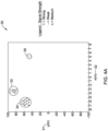
- the radar sensor may track the object(s) of interest frame by frame, and may represent the object(s) of interest using a point cloud cluster, as shown in Figure 4A .
- the point cloud cluster may be created using the Cartesian coordinate ground plane, and may be considered to be a "bird's eye” or "overhead” view of the object(s) of interest.
- the radar sensor creates a view of the object(s) of interest in a radar plane in a top-down manner.
- a controller may be operatively coupled to the radar sensor and may include software that is configured to classify the object(s) of interest, as referenced by block 115.
- the controller may be configured to receive signals from the radar sensor indicating the presence of the object(s) of interest within the operational range of the radar sensor, and the controller may determine the strength of the signals received by the radar sensor, as well as a speed of travel of the object(s) of interest, and/or a size of the point cloud cluster.
- the speed of travel may indicate the type of object(s) of interest. For example, a person walking or riding a bicycle may not be able to travel at speeds of 120 kph.
- the strength of the signal may indicate a type of material present within the object(s) of interest.
- the radar sensor may receive a strong signal from a metal object, such as a vehicle.
- an object such as an article of clothing on a person may produce a weaker signal.
- the controller may classify the object(s) of interest.
- the track(s) may be classified into one of a vehicle, a bicycle, a person, or the like.
- the controller determines if a license plate recognition (LPR) is desired for any of the vehicles currently being tracked. If LPR is desired for any of the vehicles currently being tracked, the controller determines if LPR has been performed on all vehicles being tracked, as referenced by block 125. In the example shown, if no license plate recognition (LPR) is desired for any of the vehicles currently being tracked, the method 100 does not proceed to block 130 but rather simply returns to block 105. If the controller determines that LPR is desired for at least one of the vehicles currently being tracked, the method moves on to block 130. In block 130, the controller calculates and sets the camera settings, as referenced by block 130.
- LPR license plate recognition
- the camera settings may include, for example, one or more of a shutter speed camera setting, an aperture camera setting, a focus camera setting, a zoom camera setting, a pan camera setting, and a tilt camera setting.
- the shutter speed setting and the aperture setting may be calculated based upon the fastest tracked vehicle in order to capture clear images for the all of the multiple vehicles present in the image.
- predetermined input values e.g. speed, lighting, etc.
- it is contemplated that the that the camera settings may be determined using a machine learning (ML) and/or artificial intelligence (AI) algorithm, as desired.
- ML machine learning
- AI artificial intelligence
- the controller may compute a bounding box for each vehicle being tracked using the point cloud cluster, as referenced by block 135. As shown in Figure 3B , based upon the bounding box, the controller may estimate a Region of Interest (ROI) by adding a margin of error in height and width to the bounding box, as referenced by block 140.
- ROI Region of Interest
- the margin of error may be larger.
- the margin of error may include 1-2 meters.
- the margin of error may include 0.5 meters, 0.25 meters, 0.01 meters, or any other suitable margin of error desired. When there are multiple objects of interest, there may be multiple corresponding ROIs.
- the controller may merge the ROIs into one ROI, as referenced by block 145.
- An example of this is shown in Figure 4C .
- the coordinates in the radar plane (e.g., point cloud cluster) of the merged ROI are then projected onto an image captured by the camera in an image coordinate plane (e.g. pixels), as referenced by block 150.
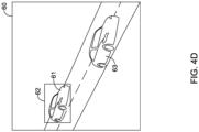
- An example of this is shown in Figure 4D , where the merged ROI only includes one ROI of the vehicle 61.
- an image of the other vehicle 63 has already been taken and is thus no longer being tracked.
- the resulting image may be called the projected ROI.
- the controller may calculate the center of the projected ROI, as referenced by block 155.
- the controller may instruct the camera to align the center of the projected ROI with the image center, and based upon the alignment, the controller may calculate the pan camera setting and the tilt camera setting, as referenced by block 175.
- the controller may then send one or more commands to direct the camera to perform a pan-tilt operation using the calculated pan camera setting and the tilt camera setting, as referenced by block 180, and to further instruct the camera to perform a zoom setting until the center of the projected ROI and the image center overlap, as referenced by block 185.
- the controller may then direct the camera to perform a focus operation (or perform an autofocus) using a focus setting for the updated Field of View (FOV), as referenced by block 190.
- FOV Field of View
- the projected ROI may be cropped and resized, such as by scaling the image up to an original image dimension, to fit the image captured by the camera, as referenced by bock 165, and perform a focus on the projected ROI, as referenced by block 170.
- FIG 4A is a schematic diagram illustrating a plurality of radar point cloud clusters on a radar image 30.
- the radar image 30 may include an X-axis 32 and a Y-axis 31, both of which indicate distance measured in meters (m).
- the radar image 30 includes three point cloud clusters 33, 34, and 35, which may indicate the presence of a three objects of interest.
- the point cloud clusters 33, 34, and 35 may be created using a Cartesian coordinate ground plane, and may be considered to be a "bird's eye” or "overhead” view of the object(s) of interest.
- the point cloud cluster 33 is located around 90 meters from a radar sensor (radar sensor 14), and includes varying signal strengths indicating the object of interest includes various materials and/or are traveling at varying speeds. For example, as shown in The Legend, the "+” indicates a strong signal, “-” indicates a weak signal, and “ ⁇ ” indicates a medium signal. As seen in the point cloud cluster 33, the image contains strong, weak, and medium strength signals. Further, the size of the point cloud cluster 33 would appear to be two meters in width, thus the indication may be that the object represented by the point cloud cluster 33 is a vehicle.
- the point cloud cluster 34 includes strong, weak, and medium strength signals, and the size of the point cloud cluster 34 would appear to be two-three meters in width, thus indicating the object represented by the point cloud cluster 34 may be a larger vehicle.
- the point cloud cluster 35 includes a weak signal and would appear to be around 1 meter in width, thus indicating that the object represented by the point cloud cluster 35 may not be a vehicle, but rather may be a person on a bicycle, a person walking, or the like.
- FIG 4B is a schematic diagram illustrating a Region of Interest (ROI) 40 including a radar cluster 41.
- the controller e.g., controller 16
- the controller may determine the size of the point cloud cluster and determine a bounding box for each object of interest, as shown in Figure 4B .
- a margin of error may be added to determine a ROI 40 for each of the objects.
- the controller may estimate the ROI 40 by adding a margin of error 42 in height and a margin of error 43 in width for the bounding box. In some cases, when the object(s) of interest are located farther away from the camera and radar sensor, the margin of error 42, 43 may be larger.
- the margin of error 42, 43 may not be fixed, and may vary based upon a distance the object of interest is away from the camera and radar sensor. In some examples, the margin of error 42, 43 may include 1-2 meters. In some examples, the margin of error 42, 43 may include 0.5 meters, 0.25 meters, 0.01 meters, or any other suitable margin of error desired, particularly as the object of interest gets closer to the camera and radar sensor.
- FIG. 4C is a schematic diagram illustrating a ROI 50 including a plurality of merged Regions of Interest (ROIs) that correspond to a plurality of objects of interest.
- the merged ROIs include a Region of Interest (ROI)-1 51, a ROI-2 52, and a ROI-3 53.
- the ROIs 51, 52, and 53 each represent a ROI for an object of interest. In this example, there are three objects of interest.
- the ROIs 51, 52, and 53 define an area within a radar plane using Cartesian coordinates (e.g. Cartesian coordinate ground plane).
- Cartesian coordinates e.g. Cartesian coordinate ground plane.
- the ROIs 51, 52, and 53 may overlap based on the coordinates of each object of interest as well as the margin of error discussed in reference to Figure 4B .
- the ROI 50 of the merged ROIs 51, 52, and 53 may then be projected onto an image captured by a camera (camera 12) by transforming the coordinates of the radar plane with the coordinates of an image plane.
- An example of the resulting image is shown in Figure 4D , but where the merged ROI only includes one ROI (e.g. of the vehicle 61).
- FIG. 4D is a schematic diagram illustrating an image 60 from a camera (e.g., camera 12) with a ROI 62 projected onto the image 60.
- the resulting image may be called the projected ROI.
- the ROI 62 has encapsulated a vehicle 61 driving toward the camera.
- a controller e.g., controller 16
- the controller may then direct the camera to perform a pan-tilt operation, and further instruct the camera to perform a zoom setting and a focus setting, producing an updated image (not shown).
- a second vehicle 63 within the image 60 may no longer include a ROI, as the vehicle 63 has been previously identified using license plate recognition (LPR) and thus is no longer tracked by the system.
- LPR license plate recognition
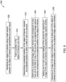
- FIG. 5 is a flow diagram showing an illustrative method 200 for operating a camera (e.g., camera 12), which may be carried out by a controller (e.g., controller 16), wherein the controller may be operatively coupled to the camera and a radar sensor (e.g., radar sensor 14).
- the controller may identify an object of interest using the radar sensor, and the object of interest may be represented as a point cloud, as referenced by block 205.
- the object of interest may include a vehicle such as a car, a motorcycle, a semi-truck, a garbage truck, a van, or the like.
- the controller may track a position of the object of interest, as referenced by block 210.
- the controller may then determine a projected position of the object of interest, wherein the projected position may be within a Field of View (FOV) of the camera, as referenced by block 215.
- the controller may determine a projected image capture window that corresponds to less than all of the FOV of the camera, wherein the projected image capture window corresponds to the projected position of the object of interest, as referenced by block 220.
- the projected image capture window may include a license plate of the vehicle.
- the method 200 may further include the controller setting one or more camera settings of the camera for capturing an image of the object of interest in the projected image capture window, as referenced by block 225.
- the one or more camera settings may include one or more of a shutter speed camera setting, an aperture camera setting, a focus camera setting, and a zoom camera setting. In some cases, the one or more camera settings may include one or more of a pan camera setting and a tilt camera setting.
- the controller may capture an image of the object of interest when at least part of the object of interest is at the projected position and in the projected image capture window, as referenced by block 230.
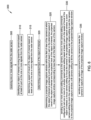
- FIG. 6 is a flow diagram showing an illustrative method 300 that may be carried out by a controller (e.g., controller 16).
- the method 300 may include the controller receiving one or more signals from a radar sensor (e.g., radar sensor 14), as referenced by block 305.
- the controller may identify an object of interest moving toward a camera (e.g., camera 12), based at least in part on the one or more signals received from the radar sensor, as referenced by block 310.
- the controller may be configured to determine a speed of travel of the object of interest based at least in part on the one or more signals from the radar sensor, as referenced by block 315, and may determine a projected track of the object of interest, as referenced by block 320.
- the method 300 may include determining a projected image capture window within a Field of View (FOV) of a camera (e.g., camera 12), at which the object of interest is projected to arrive based at least in part on the determined speed of travel of the object of interest, and the projected track of the object of interest.
- the projected image capture window may correspond to less than all of the FOV of the camera, as referenced by block 325.
- the method 300 may further include the controller sending one or more camera setting commands to the camera.
- the one or more camera setting commands may be configured to set one or more of a shutter speed camera setting, wherein the shutter speed camera setting may be based at least in part on the speed of travel of the object of interest, a focus camera setting to focus the camera on the projected image capture window, a zoom camera setting to zoom the camera to the projected image capture window, a pan camera setting to pan the camera to the projected image capture window, and a tilt camera setting to tilt the camera to the projected image capture window, as referenced by block 330.
- the controller may then be configured to send an image capture command to the camera to cause the camera to capture an image of the projected image capture window, as referenced by block 335.
- FIG. 7 is a flow diagram showing an illustrative method 400 that may be carried out by a controller (e.g., controller 16).
- the controller may be operatively coupled to a camera (e.g., camera 12) and a radar sensor (e.g., radar sensor 14).
- the controller may be configured to identify an object of interest within an operational range of the radar sensor using an output from the radar sensor, as referenced by block 405.
- the controller may then determine one or more motion parameters of the object of interest, as referenced by block 410, and set one or more camera settings for the camera based on the one or more motion parameters of the object of interest, as referenced by block 415.
- the controller may cause the camera to capture an image of the object of interest, as referenced by block 420.
Landscapes
- Engineering & Computer Science (AREA)
- Physics & Mathematics (AREA)
- General Physics & Mathematics (AREA)
- Multimedia (AREA)
- Theoretical Computer Science (AREA)
- Mathematical Physics (AREA)
- Signal Processing (AREA)
- Mathematical Analysis (AREA)
- Mathematical Optimization (AREA)
- Computational Mathematics (AREA)
- Pure & Applied Mathematics (AREA)
- Data Mining & Analysis (AREA)
- Radar, Positioning & Navigation (AREA)
- Remote Sensing (AREA)
- Software Systems (AREA)
- General Engineering & Computer Science (AREA)
- Databases & Information Systems (AREA)
- Algebra (AREA)
- Operations Research (AREA)
- Computer Networks & Wireless Communication (AREA)
- Computer Vision & Pattern Recognition (AREA)
- Traffic Control Systems (AREA)
Applications Claiming Priority (1)
| Application Number | Priority Date | Filing Date | Title |
|---|---|---|---|
| IN202211027975 | 2022-05-16 |
Publications (1)
| Publication Number | Publication Date |
|---|---|
| EP4332911A1 true EP4332911A1 (fr) | 2024-03-06 |
Family
ID=86282550
Family Applications (1)
| Application Number | Title | Priority Date | Filing Date |
|---|---|---|---|
| EP23170916.3A Withdrawn EP4332911A1 (fr) | 2022-05-16 | 2023-05-01 | Configuration automatique de réglages de caméra à l'aide d'un radar |
Country Status (3)
| Country | Link |
|---|---|
| US (1) | US20230368537A1 (fr) |
| EP (1) | EP4332911A1 (fr) |
| CN (1) | CN117082332A (fr) |
Cited By (1)
| Publication number | Priority date | Publication date | Assignee | Title |
|---|---|---|---|---|
| GB2626423A (en) * | 2022-12-08 | 2024-07-24 | Honeywell Int Inc | Occupancy estimation based on multiple sensor inputs |
Families Citing this family (1)
| Publication number | Priority date | Publication date | Assignee | Title |
|---|---|---|---|---|
| US12356123B2 (en) * | 2023-06-02 | 2025-07-08 | Contego Al Incorporated | Real time security alert system, method and computer program |
Citations (3)
| Publication number | Priority date | Publication date | Assignee | Title |
|---|---|---|---|---|
| US10893183B1 (en) * | 2019-11-18 | 2021-01-12 | GM Global Technology Operations LLC | On-vehicle imaging system |
| US20210025975A1 (en) * | 2019-07-26 | 2021-01-28 | Dedrone Holdings, Inc. | Systems, methods, apparatuses, and devices for radar-based identifying, tracking, and managing of unmanned aerial vehicles |
| US20220128701A1 (en) * | 2020-10-23 | 2022-04-28 | Argo AI, LLC | Systems and methods for camera-lidar fused object detection with lidar-to-image detection matching |
-
2023
- 2023-05-01 EP EP23170916.3A patent/EP4332911A1/fr not_active Withdrawn
- 2023-05-10 US US18/314,904 patent/US20230368537A1/en active Pending
- 2023-05-12 CN CN202310536621.0A patent/CN117082332A/zh active Pending
Patent Citations (3)
| Publication number | Priority date | Publication date | Assignee | Title |
|---|---|---|---|---|
| US20210025975A1 (en) * | 2019-07-26 | 2021-01-28 | Dedrone Holdings, Inc. | Systems, methods, apparatuses, and devices for radar-based identifying, tracking, and managing of unmanned aerial vehicles |
| US10893183B1 (en) * | 2019-11-18 | 2021-01-12 | GM Global Technology Operations LLC | On-vehicle imaging system |
| US20220128701A1 (en) * | 2020-10-23 | 2022-04-28 | Argo AI, LLC | Systems and methods for camera-lidar fused object detection with lidar-to-image detection matching |
Non-Patent Citations (1)
| Title |
|---|
| No Search * |
Cited By (2)
| Publication number | Priority date | Publication date | Assignee | Title |
|---|---|---|---|---|
| GB2626423A (en) * | 2022-12-08 | 2024-07-24 | Honeywell Int Inc | Occupancy estimation based on multiple sensor inputs |
| GB2626423B (en) * | 2022-12-08 | 2025-03-12 | Honeywell Int Inc | Occupancy estimation based on multiple sensor inputs |
Also Published As
| Publication number | Publication date |
|---|---|
| CN117082332A (zh) | 2023-11-17 |
| US20230368537A1 (en) | 2023-11-16 |
Similar Documents
| Publication | Publication Date | Title |
|---|---|---|
| US11881039B2 (en) | License plate reading system with enhancements | |
| US11978260B2 (en) | Systems and methods for rapid license plate reading | |
| US11380105B2 (en) | Identification and classification of traffic conflicts | |
| CN101303735B (zh) | 探测车辆盲点区域内运动物体的方法及盲点探测装置 | |
| CN107845104B (zh) | 一种检测超车车辆的方法、相关处理系统、超车车辆检测系统以及车辆 | |
| US9975550B2 (en) | Movement trajectory predicting device and movement trajectory predicting method | |
| CN109703460B (zh) | 多摄像头的复杂场景自适应车辆碰撞预警装置及预警方法 | |
| JP7003972B2 (ja) | 距離推定装置、距離推定方法及び距離推定用コンピュータプログラム | |
| CN105825185B (zh) | 车辆防碰撞预警方法及装置 | |
| CN109074069A (zh) | 具有改进的视觉检测能力的自主车辆 | |
| US20230368537A1 (en) | Automatic configuration of camera settings using radar | |
| CN107229906A (zh) | 一种基于可变部件模型算法的汽车超车预警方法 | |
| CN120932455B (zh) | 一种交通风险实时告警方法及系统 | |
| CN114898325A (zh) | 一种车辆危险变道检测方法、装置及电子设备 | |
| CN115953328B (zh) | 一种目标矫正方法、系统及电子设备 | |
| CN114863695B (zh) | 一种基于车载激光和摄像机的超标车辆检测系统和方法 | |
| KR20220036240A (ko) | 교통정보 분석장치 및 방법 | |
| KR102497488B1 (ko) | 주행속도에 따른 인식범위조절이 가능한 자율주행 차량의 영상인식 장치 | |
| CN119152456A (zh) | 车辆周围的环境感知方法、装置、设备及存储介质 | |
| CN120048133B (zh) | 一种车路协调系统及车辆通行管理方法 | |
| KR102340902B1 (ko) | 스쿨존을 모니터링하는 장치 및 방법 | |
| JP6980887B1 (ja) | 移動体検知システム | |
| CN121650384A (zh) | 一种车辆悬架调节方法、装置、车辆和存储介质 | |
| CN120708181A (zh) | 用于车辆感知系统的增量学习的方法和装置 | |
| CN121469554A (zh) | 车辆碰撞预警方法、装置以及计算机设备 |
Legal Events
| Date | Code | Title | Description |
|---|---|---|---|
| PUAI | Public reference made under article 153(3) epc to a published international application that has entered the european phase |
Free format text: ORIGINAL CODE: 0009012 |
|
| STAA | Information on the status of an ep patent application or granted ep patent |
Free format text: STATUS: REQUEST FOR EXAMINATION WAS MADE |
|
| 17P | Request for examination filed |
Effective date: 20230501 |
|
| AK | Designated contracting states |
Kind code of ref document: A1 Designated state(s): AL AT BE BG CH CY CZ DE DK EE ES FI FR GB GR HR HU IE IS IT LI LT LU LV MC ME MK MT NL NO PL PT RO RS SE SI SK SM TR |
|
| STAA | Information on the status of an ep patent application or granted ep patent |
Free format text: STATUS: EXAMINATION IS IN PROGRESS |
|
| 17Q | First examination report despatched |
Effective date: 20251017 |
|
| STAA | Information on the status of an ep patent application or granted ep patent |
Free format text: STATUS: THE APPLICATION IS DEEMED TO BE WITHDRAWN |
|
| 18D | Application deemed to be withdrawn |
Effective date: 20260218 |