EP4333093A1 - Mehrschichtkörper für wasserfreie sekundärbatterien, verbindungszusammensetzung und wasserfreie sekundärbatterie - Google Patents
Mehrschichtkörper für wasserfreie sekundärbatterien, verbindungszusammensetzung und wasserfreie sekundärbatterie Download PDFInfo
- Publication number
- EP4333093A1 EP4333093A1 EP22795537.4A EP22795537A EP4333093A1 EP 4333093 A1 EP4333093 A1 EP 4333093A1 EP 22795537 A EP22795537 A EP 22795537A EP 4333093 A1 EP4333093 A1 EP 4333093A1
- Authority
- EP
- European Patent Office
- Prior art keywords
- adhesion
- composition
- separator
- electrode
- particulate polymer
- Prior art date
- Legal status (The legal status is an assumption and is not a legal conclusion. Google has not performed a legal analysis and makes no representation as to the accuracy of the status listed.)
- Pending
Links
Images

Classifications
-
- H—ELECTRICITY
- H01—ELECTRIC ELEMENTS
- H01M—PROCESSES OR MEANS, e.g. BATTERIES, FOR THE DIRECT CONVERSION OF CHEMICAL ENERGY INTO ELECTRICAL ENERGY
- H01M4/00—Electrodes
- H01M4/02—Electrodes composed of, or comprising, active material
- H01M4/13—Electrodes for accumulators with non-aqueous electrolyte, e.g. for lithium-accumulators; Processes of manufacture thereof
-
- H—ELECTRICITY
- H01—ELECTRIC ELEMENTS
- H01M—PROCESSES OR MEANS, e.g. BATTERIES, FOR THE DIRECT CONVERSION OF CHEMICAL ENERGY INTO ELECTRICAL ENERGY
- H01M50/00—Constructional details or processes of manufacture of the non-active parts of electrochemical cells other than fuel cells, e.g. hybrid cells
- H01M50/40—Separators; Membranes; Diaphragms; Spacing elements inside cells
- H01M50/46—Separators, membranes or diaphragms characterised by their combination with electrodes
- H01M50/461—Separators, membranes or diaphragms characterised by their combination with electrodes with adhesive layers between electrodes and separators
-
- H—ELECTRICITY
- H01—ELECTRIC ELEMENTS
- H01M—PROCESSES OR MEANS, e.g. BATTERIES, FOR THE DIRECT CONVERSION OF CHEMICAL ENERGY INTO ELECTRICAL ENERGY
- H01M10/00—Secondary cells; Manufacture thereof
- H01M10/05—Accumulators with non-aqueous electrolyte
- H01M10/052—Li-accumulators
- H01M10/0525—Rocking-chair batteries, i.e. batteries with lithium insertion or intercalation in both electrodes; Lithium-ion batteries
-
- H—ELECTRICITY
- H01—ELECTRIC ELEMENTS
- H01M—PROCESSES OR MEANS, e.g. BATTERIES, FOR THE DIRECT CONVERSION OF CHEMICAL ENERGY INTO ELECTRICAL ENERGY
- H01M50/00—Constructional details or processes of manufacture of the non-active parts of electrochemical cells other than fuel cells, e.g. hybrid cells
- H01M50/40—Separators; Membranes; Diaphragms; Spacing elements inside cells
- H01M50/409—Separators, membranes or diaphragms characterised by the material
- H01M50/443—Particulate material
-
- H—ELECTRICITY
- H01—ELECTRIC ELEMENTS
- H01M—PROCESSES OR MEANS, e.g. BATTERIES, FOR THE DIRECT CONVERSION OF CHEMICAL ENERGY INTO ELECTRICAL ENERGY
- H01M50/00—Constructional details or processes of manufacture of the non-active parts of electrochemical cells other than fuel cells, e.g. hybrid cells
- H01M50/40—Separators; Membranes; Diaphragms; Spacing elements inside cells
- H01M50/409—Separators, membranes or diaphragms characterised by the material
- H01M50/449—Separators, membranes or diaphragms characterised by the material having a layered structure
-
- H—ELECTRICITY
- H01—ELECTRIC ELEMENTS
- H01M—PROCESSES OR MEANS, e.g. BATTERIES, FOR THE DIRECT CONVERSION OF CHEMICAL ENERGY INTO ELECTRICAL ENERGY
- H01M50/00—Constructional details or processes of manufacture of the non-active parts of electrochemical cells other than fuel cells, e.g. hybrid cells
- H01M50/40—Separators; Membranes; Diaphragms; Spacing elements inside cells
- H01M50/463—Separators, membranes or diaphragms characterised by their shape
-
- H—ELECTRICITY
- H01—ELECTRIC ELEMENTS
- H01M—PROCESSES OR MEANS, e.g. BATTERIES, FOR THE DIRECT CONVERSION OF CHEMICAL ENERGY INTO ELECTRICAL ENERGY
- H01M50/00—Constructional details or processes of manufacture of the non-active parts of electrochemical cells other than fuel cells, e.g. hybrid cells
- H01M50/40—Separators; Membranes; Diaphragms; Spacing elements inside cells
- H01M50/489—Separators, membranes, diaphragms or spacing elements inside the cells, characterised by their physical properties, e.g. swelling degree, hydrophilicity or shut down properties
-
- Y—GENERAL TAGGING OF NEW TECHNOLOGICAL DEVELOPMENTS; GENERAL TAGGING OF CROSS-SECTIONAL TECHNOLOGIES SPANNING OVER SEVERAL SECTIONS OF THE IPC; TECHNICAL SUBJECTS COVERED BY FORMER USPC CROSS-REFERENCE ART COLLECTIONS [XRACs] AND DIGESTS
- Y02—TECHNOLOGIES OR APPLICATIONS FOR MITIGATION OR ADAPTATION AGAINST CLIMATE CHANGE
- Y02E—REDUCTION OF GREENHOUSE GAS [GHG] EMISSIONS, RELATED TO ENERGY GENERATION, TRANSMISSION OR DISTRIBUTION
- Y02E60/00—Enabling technologies; Technologies with a potential or indirect contribution to GHG emissions mitigation
- Y02E60/10—Energy storage using batteries
-
- Y—GENERAL TAGGING OF NEW TECHNOLOGICAL DEVELOPMENTS; GENERAL TAGGING OF CROSS-SECTIONAL TECHNOLOGIES SPANNING OVER SEVERAL SECTIONS OF THE IPC; TECHNICAL SUBJECTS COVERED BY FORMER USPC CROSS-REFERENCE ART COLLECTIONS [XRACs] AND DIGESTS
- Y02—TECHNOLOGIES OR APPLICATIONS FOR MITIGATION OR ADAPTATION AGAINST CLIMATE CHANGE
- Y02P—CLIMATE CHANGE MITIGATION TECHNOLOGIES IN THE PRODUCTION OR PROCESSING OF GOODS
- Y02P70/00—Climate change mitigation technologies in the production process for final industrial or consumer products
- Y02P70/50—Manufacturing or production processes characterised by the final manufactured product
Definitions
- the present disclosure relates to a laminate for a non-aqueous secondary battery, a composition for adhesion, and a non-aqueous secondary battery.
- Non-aqueous secondary batteries such as lithium ion secondary batteries have characteristics such as compact size, light weight, high energy-density, and the ability to be repeatedly charged and discharged, and are used in a wide variety of applications.
- a secondary battery generally includes battery members such as a positive electrode, a negative electrode, and a separator that isolates the positive electrode and the negative electrode from each other and prevents short-circuiting between the positive and negative electrodes.
- an electrode and a separator that have not yet been immersed in electrolyte solution may be pressure bonded to obtain a laminate (hereinafter, also referred to as a "laminate for a secondary battery"), and then this laminate may, as necessary, be cut to a desired size or be stacked, folded, or wound.
- a laminate hereinafter, also referred to as a "laminate for a secondary battery”
- Patent Literature (PTL) 1 discloses a laminate for a secondary battery that is obtained by adhering an electrode and a separator via an adhesive material.
- the adhesive material is obtained by applying a slurry for a non-aqueous secondary battery containing a particulate polymer having a core-shell structure, a specific amount of a polyhydric alcohol compound, and water onto the electrode by an inkjet method and then drying the slurry for a non-aqueous secondary battery.
- PTL 2 discloses a laminate for a secondary battery that is obtained by adhering an electrode and a separator via an adhesive layer.
- the adhesive layer is obtained by applying a composition for an adhesive layer that contains organic particles having a core-shell structure, a thixotropic agent, and water and that satisfies specific properties onto a porous membrane layer-equipped separator by an inkjet method and then drying the composition for an adhesive layer.
- a laminate for a secondary battery has strong adhesion between an electrode and a separator and is capable of forming a secondary battery having excellent battery characteristics such as output characteristics.
- a laminate for a secondary battery obtained according to the conventional techniques described above there is room for further improvement in terms of simultaneously achieving all of the above-described attributes to high levels.
- one object of the present disclosure is to provide a laminate for a non-aqueous secondary battery that has strong adhesion between an electrode and a separator and is capable of forming a secondary battery having excellent output characteristics.
- Another object of the present disclosure is to provide a composition for adhesion that can suitably be used as a material forming an adhesive layer of a presently disclosed laminate for a non-aqueous secondary battery.
- Yet another object of the present disclosure is to provide a secondary battery having excellent battery characteristics such as output characteristics.
- the inventors conducted diligent investigation with the aim of solving the problems described above.
- the inventors discovered that in a situation in which a composition for adhesion that forms an adhesive layer adhering an electrode and a separator in a laminate for a non-aqueous secondary battery satisfies a specific relationship with at least one of the electrode and the separator, the electrode and the separator are strongly adhered, and this laminate for a non-aqueous secondary battery is capable of forming a secondary battery having excellent output characteristics.
- the inventors completed the present disclosure.
- a presently disclosed laminate for a non-aqueous secondary battery comprises an electrode and a separator that are adhered via an adhesive layer, wherein the adhesive layer is a dried product of a composition for adhesion that contains a particulate polymer, and a relationship between the composition for adhesion and at least one of the electrode and the separator satisfies formula (1), shown below. 20 ⁇ Remaining proportion of coating liquid % ⁇ 100
- C(PET) is volume of the composition for adhesion remaining on a polyethylene terephthalate substrate at a drying completion point at which volume change of the composition for adhesion reaches saturation when volume change of the composition for adhesion on the polyethylene terephthalate substrate is measured over time after 1,000 pL of the composition for adhesion is dripped onto the polyethylene terephthalate substrate; and C(substrate) is volume of the composition for adhesion remaining on the electrode or the separator when the drying completion point is reached after 1,000 pL of the composition for adhesion is dripped onto the electrode or the separator.
- the laminate for a non-aqueous secondary battery in which a relationship between the composition for adhesion and at least one of the electrode and the separator satisfies the preceding formula (1) in this manner has strong adhesion between the electrode and the separator and is capable of forming a non-aqueous secondary battery having excellent output characteristics.
- C(PET) and "C(substrate)" referred to in the present disclosure can be determined according to a method described in the EXAMPLES section of the present specification.
- a presently disclosed laminate for a non-aqueous secondary battery comprises an electrode and a separator that are adhered via an adhesive layer, wherein the adhesive layer is a dried product of a composition for adhesion that contains a particulate polymer, and a relationship between a particle size distribution (D90) of the composition for adhesion and at least one of surface roughness (Sa) of the electrode and surface roughness (Sa) of the separator satisfies formula (3), shown below.
- Particle size distribution D 90 of composition for adhesion ⁇ m ⁇ Surface roughness Sa of electrode ⁇ m or Surface roughness Sa of separator ⁇ m > ⁇ 0.25
- the laminate for a non-aqueous secondary battery in which a relationship between the particle size distribution (D90) [ ⁇ m] of the composition for adhesion and at least one of surface roughness (Sa) [ ⁇ m] of the electrode and surface roughness (Sa) [ ⁇ m] of the separator satisfies the preceding formula (3) in this manner has strong adhesion between the electrode and the separator and is capable of forming a non-aqueous secondary battery having excellent output characteristics.
- the adhesive layer is formed of a plurality of dot-like adhesive layers, dot diameter per one of the dot-like adhesive layers is 200 ⁇ m or more, and the dot-like adhesive layers have a crater-like uneven shape.
- the laminate for a non-aqueous secondary battery in which the adhesive layer is formed of a plurality of dot-like adhesive layers, the dot diameter per one dot-like adhesive layer is 200 ⁇ m or more, and the dot-like adhesive layers have a crater-like uneven shape in this manner has even stronger adhesion between the electrode and the separator and is capable of forming a non-aqueous secondary battery having further improved output characteristics.
- the "dot diameter" referred to in the present disclosure can be measured according to a method described in the EXAMPLES section of the present specification.
- a presently disclosed composition for adhesion comprises a particulate polymer and is used for any one of the laminates for a non-aqueous secondary battery set forth above, wherein the particulate polymer has a core-shell structure including a core portion and a shell portion partially covering an outer surface of the core portion.
- the particulate polymer may include two or more particulate polymers having different volume-average particle diameters, and at least one of the particulate polymers may have the core-shell structure.
- composition for adhesion that contains a particulate polymer having a core-shell structure including a core portion and a shell portion partially covering an outer surface of the core portion in this manner can suitably be used as a material for forming an adhesive layer that strongly adheres an electrode and a separator in a laminate for a non-aqueous secondary battery.
- a presently disclosed non-aqueous secondary battery comprises any one of the laminates for a non-aqueous secondary battery set forth above.
- the presently disclosed non-aqueous secondary battery has excellent battery characteristics such as output characteristics as a result of including the laminate for a non-aqueous secondary battery set forth above.
- a laminate for a non-aqueous secondary battery that has strong adhesion between an electrode and a separator and is capable of forming a non-aqueous secondary battery having excellent output characteristics.
- composition for adhesion that can suitably be used as a material forming an adhesive layer of the presently disclosed laminate for a non-aqueous secondary battery.
- a presently disclosed laminate for a non-aqueous secondary battery can be used in production of a non-aqueous secondary battery such as a lithium ion secondary battery, for example.
- a presently disclosed composition for adhesion can be used as a material forming an adhesive layer that adheres an electrode and a separator in a laminate for a non-aqueous secondary battery.
- a presently disclosed non-aqueous secondary battery includes the presently disclosed laminate for a non-aqueous secondary battery.
- the presently disclosed laminate for a non-aqueous secondary battery is a laminate for a non-aqueous secondary battery that includes an electrode and a separator and in which the electrode and the separator are adhered via an adhesive layer.
- the adhesive layer that adheres the electrode and the separator is a dried product of a composition for adhesion that contains a particulate polymer, and a relationship between the composition for adhesion and at least one of the electrode and the separator satisfies the following formula (1). 20 ⁇ Remaining proportion of coating liquid % ⁇ 100
- C(PET) is the volume of the composition for adhesion remaining on a polyethylene terephthalate substrate at a drying completion point at which volume change of the composition for adhesion reaches saturation when volume change of the composition for adhesion on the polyethylene terephthalate substrate is measured over time after 1,000 pL of the composition for adhesion is dripped onto the polyethylene terephthalate substrate.
- C(substrate) is the volume of the composition for adhesion remaining on the electrode or the separator when the drying completion point is reached after 1,000 pL of the composition for adhesion is dripped onto the electrode or the separator.
- a relationship between a particle size distribution (D90) of the composition for adhesion and at least one of surface roughness (Sa) of the electrode and surface roughness (Sa) [ ⁇ m] of the separator satisfies the following formula (3).
- the presently disclosed laminate for a non-aqueous secondary battery has strong adhesion between the electrode and the separator and is capable of forming a secondary battery having excellent output characteristics as a result of satisfying the relationship in formula (1) and/or formula (3). Moreover, by using the presently disclosed laminate for a non-aqueous secondary battery in a secondary battery, it is possible to inhibit deposition of metal such as lithium (Li) at an electrode surface during charging of the secondary battery.
- metal such as lithium (Li)
- the presently disclosed laminate for a non-aqueous secondary battery has strong adhesion between the electrode and the separator and is capable of forming a secondary battery having excellent output characteristics and why deposition of metal such as lithium (Li) at an electrode surface during charging of a secondary battery can be inhibited by using the presently disclosed laminate for a non-aqueous secondary battery in a secondary battery, the reason for this is presumed to be as follows.
- the adhesive layer that adheres the electrode and the separator is formed of a dried product of a composition for adhesion that contains a particulate polymer. Consequently, a coffee stain effect that arises during drying of the composition for adhesion causes concentrated deposition of the particulate polymer at a peripheral part of the adhesive layer, thereby increasing the thickness of the peripheral part of the adhesive layer and decreasing the thickness of a central part of the adhesive layer.
- the adhesive layer that is a dried product of the composition for adhesion containing the particulate polymer has an uneven shape in which the peripheral part has a raised shape and the central part has a depressed shape.
- the adhesive layer having a higher height at the peripheral part having a raised shape the electrode and the separator are strongly adhered via the adhesive layer.
- the remaining proportion of coating liquid is preferably 50% or more, more preferably 70% or more, and preferably 80% or more from a viewpoint of more strongly adhering the electrode and the separator.
- the value of "particle size distribution (D90) of composition for adhesion - surface roughness (Sa) of electrode [ ⁇ m] or surface roughness (Sa) of separator [ ⁇ m]” is preferably 0.1 or more, and more preferably 0.2 or more from a viewpoint of more strongly adhering the electrode and the separator.
- the remaining proportion of coating liquid can be controlled by altering the volume-average particle diameter of the particulate polymer that is contained in the composition for adhesion, the surface roughness of the electrode or the separator, the drying temperature during formation of the adhesive layer through drying of the composition for adhesion, and so forth.
- the particle size distribution (D90) of the composition for adhesion can be controlled by altering the volume-average particle diameter of the particulate polymer that is contained in the composition for adhesion, the amount of the particulate polymer that is contained in the composition for adhesion, and so forth.
- the surface roughness (Sa) [ ⁇ m] of the electrode can be adjusted mainly through control of the surface roughness of a roll in pressing and the density of the electrode after pressing. Also, the surface roughness (Sa) [ ⁇ m] of the separator can be adjusted, for example, through selection of the particle diameter of a ceramic that is used in the case of a separator that is coated with a ceramic as a heat-resistant layer.
- the electrode that is included in the presently disclosed laminate for a non-aqueous secondary battery may be just a positive electrode, just a negative electrode, or both a positive electrode and a negative electrode.
- the number of positive electrodes, the number of negative electrodes, and the number of separators included in the laminate for a non-aqueous secondary battery may be 1 or may be 2 or more.
- the structure of the presently disclosed laminate for a non-aqueous secondary battery may be any of the following structures (1) to (6).
- the electrode is not specifically limited and can, for example, be an electrode formed of an electrode substrate including an electrode mixed material layer formed on one surface or both surfaces of a current collector or an electrode further including a porous membrane layer formed on an electrode mixed material layer of an electrode substrate.
- the current collector, electrode mixed material layer, and porous membrane layer are not specifically limited and can be any current collector, electrode mixed material layer, and porous membrane layer that can be used in the field of secondary batteries, such as any of those described in JP2013-145763A , for example.
- the porous membrane layer is a layer containing nonconductive particles such as described in JP2013-145763A , for example.
- the surface roughness (Sa) of the electrode is preferably 0.1 ⁇ m or more, and is preferably less than 1.0 ⁇ m.
- the separator is not specifically limited and can, for example, be a separator formed of a separator substrate or a separator including a porous membrane layer formed on one surface or both surfaces of a separator substrate.
- the separator substrate and the porous membrane layer are not specifically limited and can be any separator substrate and porous membrane layer that can be used in the field of secondary batteries, such as any of those described in JP2012-204303A and JP2013-145763A , for example.
- the surface roughness (Sa) of the separator is preferably 0.05 ⁇ m or more, and is preferably less than 1.0 ⁇ m.
- the adhesive layer is provided at a surface of at least one of the electrode and the separator in the presently disclosed laminate for a non-aqueous secondary battery and is a material that adheres the electrode and the separator.
- the adhesive layer is a dried product of a composition for adhesion that contains a particulate polymer. Note that although the particulate polymer is present in a particulate form in the composition for adhesion, the particulate polymer may have a particulate form or may have any other form in the adhesive layer.
- the composition for adhesion is a material that forms the adhesive layer of the presently disclosed laminate for a non-aqueous secondary battery and is required to contain a particulate polymer.
- the composition for adhesion is normally a slurry composition having a particulate polymer dispersed in a solvent and can optionally contain other components besides the particulate polymer.
- the particulate polymer contained in the composition for adhesion is a component that functions as a binder in the adhesive layer adhering the electrode and the separator.
- a particulate polymer that has a core-shell structure and a particulate polymer that does not have a core-shell structure may be used as the particulate polymer in the present disclosure, it is preferable to use a particulate polymer having a core-shell structure.
- the particulate polymer having a core-shell structure has a core-shell structure that includes a core portion and a shell portion covering an outer surface of the core portion.
- the shell portion may completely cover the outer surface of the core portion or may partially cover the outer surface of the core portion.
- the shell portion is still considered to be a shell portion that partially covers the outer surface of the core portion so long as pores are formed that pass between inside and outside of the shell portion.
- the particulate polymer may include any constituent element other than the core portion and the shell portion described above so long as the expected effects are not significantly lost.
- the particulate polymer may, for example, include a portion inside of the core portion that is formed of a different polymer to the core portion.
- a residual seed particle may be present inside of the core portion in a situation in which seed particles are used in production of the particulate polymer by seeded polymerization.
- the particulate polymer is composed of only the core portion and the shell portion.
- the glass-transition temperature of a polymer of the core portion of the particulate polymer is preferably 25°C or lower, more preferably 10°C or lower, and even more preferably 0°C or lower.
- the glass-transition temperature of the polymer of the core portion is not higher than any of the upper limits set forth above, the polymer of the core portion can display good adhesiveness, and the electrode and the separator can be even more strongly adhered via the adhesive layer upon pressing at normal temperature.
- glass-transition temperature of the polymer of the core portion can be adjusted by, for example, altering the types and proportions of monomers used in production of the polymer of the core portion.
- Examples of monomers that may be used to produce the polymer of the core portion include vinyl chloride monomers such as vinyl chloride and vinylidene chloride; vinyl acetate monomers such as vinyl acetate; aromatic vinyl monomers such as styrene, ⁇ -methylstyrene, styrene sulfonic acid, butoxystyrene, and vinylnaphthalene; vinyl amine monomers such as vinyl amine; vinyl amide monomers such as N-vinylformamide and N-vinylacetamide; non-fluorine containing (meth)acrylic acid ester monomers such as methyl acrylate, ethyl acrylate, butyl acrylate (also referred to as acrylic acid butyl), 2-ethylhexyl acrylate, methyl methacrylate, ethyl methacrylate, butyl methacrylate, and cyclohexyl methacrylate; (meth)acrylamide monomers such as acrylamide and me
- (meth)acryl is used to indicate “acryl” and/or “methacryl”
- (meth)acrylonitrile is used to indicate “acrylonitrile” and/or “methacrylonitrile”.
- a (meth)acrylic acid ester monomer as a monomer used in production of the polymer of the core portion from a viewpoint of more strongly adhering the electrode and the separator via the adhesive layer, and it is more preferable to use a (meth)acrylic acid ester monomer and an aromatic vinyl monomer in combination or to use a (meth)acrylic acid ester monomer and a (meth)acrylonitrile monomer in combination, and particularly preferable to use a (meth)acrylic acid ester monomer and an aromatic vinyl monomer in combination as monomers used in production of the polymer of the core portion.
- the polymer of the core portion preferably includes at least a (meth)acrylic acid ester monomer unit, more preferably includes a (meth)acrylic acid ester monomer unit and an aromatic vinyl monomer unit or a (meth)acrylonitrile monomer unit, and even more preferably includes a (meth)acrylic acid ester monomer unit and an aromatic vinyl monomer unit.
- (meth)acrylic acid ester monomer refers to a monofunctional (meth)acrylic acid ester monomer that includes only one group displaying polymerization reactivity.
- the proportion constituted by (meth)acrylic acid ester monomer units in the polymer of the core portion when all repeating units (all monomer units) included in the polymer of the core portion are taken to be 100 mass% is preferably 5 mass% or more, more preferably 10 mass% or more, and particularly preferably 20 mass% or more, and is preferably 80 mass% or less, and more preferably 70 mass% or less.
- the proportion constituted by aromatic vinyl monomer units in the polymer of the core portion when all repeating units (all monomer units) included in the polymer of the core portion are taken to be 100 mass% is preferably 15 mass% or more, more preferably 20 mass% or more, and particularly preferably 25 mass% or more, and is preferably 95 mass% or less, more preferably 80 mass% or less, and particularly preferably 70 mass% or less.
- the proportion constituted by (meth)acrylonitrile monomer units in the polymer of the core portion when all repeating units (all monomer units) included in the polymer of the core portion are taken to be 100 mass% is preferably 5 mass% or more, more preferably 10 mass% or more, and particularly preferably 15 mass% or more, and is preferably 30 mass% or less, and more preferably 25 mass% or less.
- the polymer of the core portion can also include an acid group-containing monomer unit.
- acid group-containing monomers that can form an acid group-containing monomer unit include monomers having an acid group such as carboxy group-containing monomers, sulfo group-containing monomers, and phosphate group-containing monomers.
- carboxy group-containing monomers include monocarboxylic acids and dicarboxylic acids.
- monocarboxylic acids include acrylic acid, methacrylic acid, and crotonic acid.
- dicarboxylic acids include maleic acid, fumaric acid, and itaconic acid.
- sulfo group-containing monomers examples include vinyl sulfonic acid, methyl vinyl sulfonic acid, (meth)allyl sulfonic acid, (meth)acrylic acid 2-sulfoethyl, 2-acrylamido-2-methylpropane sulfonic acid, and 3-allyloxy-2-hydroxypropane sulfonic acid.
- phosphate group-containing monomers examples include 2-(meth)acryloyloxy ethyl phosphate, methyl-2-(meth)acryloyloxy ethyl phosphate, and ethyl-(meth)acryloyloxyethyl phosphate.
- (meth)allyl is used to indicate “allyl” and/or “methallyl”
- (meth)acryloyl is used to indicate “acryloyl” and/or “methacryloyl”.
- carboxy group-containing monomers are preferable, of which, monocarboxylic acids are preferable, and (meth)acrylic acid is more preferable.
- One acid group-containing monomer may be used individually, or two or more acid group-containing monomers may be used in combination in a freely selected ratio.
- the proportion constituted by acid group-containing monomer units in the polymer of the core portion when all repeating units (all monomer units) included in the polymer of the core portion are taken to be 100 mass% is preferably 0.1 mass% or more, and more preferably 1 mass% or more, and is preferably 15 mass% or less, and more preferably 10 mass% or less.
- the polymer of the core portion preferably includes a cross-linkable monomer unit in addition to the monomer units described above.
- a cross-linkable monomer that can form a cross-linkable monomer unit is a monomer that can form a cross-linked structure during polymerization or after polymerization upon heating or irradiation with energy rays.
- cross-linkable monomers examples include polyfunctional monomers having at least two groups that display polymerization reactivity in the monomer.
- polyfunctional monomers include divinyl monomers such as divinylbenzene, 1,3-butadiene, isoprene, and allyl methacrylate; di(meth)acrylic acid ester monomers such as ethylene dimethacrylate, diethylene glycol dimethacrylate, ethylene glycol dimethacrylate, diethylene glycol diacrylate, and 1,3-butylene glycol diacrylate; tri(meth)acrylic acid ester monomers such as trimethylolpropane trimethacrylate and trimethylolpropane triacrylate; epoxy group-containing ethylenically unsaturated monomers such as allyl glycidyl ether and glycidyl methacrylate; and ⁇ -methacryloxypropyltrimethoxysilane.
- di(meth)acrylic acid ester monomers such as ethylene dim
- the proportion constituted by cross-linkable monomer units in the polymer of the core portion when all repeating units (all monomer units) included in the polymer of the core portion are taken to be 100 mass% is preferably 0.1 mass% or more, more preferably 0.2 mass% or more, and particularly preferably 0.4 mass% or more, and is preferably 10 mass% or less, more preferably 5 mass% or less, and particularly preferably 3 mass% or less.
- the glass-transition temperature of a polymer of the shell portion of the particulate polymer is preferably 50°C or higher, more preferably 55°C or higher, and even more preferably 60°C or higher, and is preferably 200°C or lower, and more preferably 120°C or lower.
- the glass-transition temperature of the polymer of the shell portion is not lower than any of the lower limits set forth above, it is possible to further improve inkjet ejection characteristics in a situation in which the composition for adhesion is supplied onto a surface of at least one of the electrode and the separator by an inkjet method.
- the glass-transition temperature of the polymer of the shell portion is not higher than any of the upper limits set forth above, it is possible to even more strongly adhere the electrode and the separator via the adhesive layer at normal temperature because the particulate polymer is softened to a suitable degree.
- glass-transition temperature of the polymer of the shell portion can be adjusted by, for example, altering the types and proportions of monomers used in production of the polymer of the shell portion.
- the glass-transition temperature of the polymer of the shell portion is preferably at least 25°C higher than the glass-transition temperature of the polymer of the core portion described above, and is more preferably at least 50°C higher than the glass-transition temperature of the polymer of the core portion described above.
- Examples of monomers that can be used to produce the polymer of the shell portion include the same monomers as given as examples of monomers that can be used to produce the polymer of the core portion.
- One of such monomers may be used individually, or two or more of such monomers may be used in combination in a freely selected ratio.
- the polymer of the shell portion preferably includes either or both of a (meth)acrylic acid ester monomer unit and an aromatic vinyl monomer unit, and more preferably includes both a (meth)acrylic acid ester monomer unit and an aromatic vinyl monomer unit.
- the proportion constituted by (meth)acrylic acid ester monomer units in the polymer of the shell portion when all repeating units (all monomer units) included in the polymer of the shell portion are taken to be 100 mass% is preferably 10 mass% or more, more preferably 20 mass% or more, and even more preferably 32.5 mass% or more, and is preferably 90 mass% or less, and more preferably 85 mass% or less.
- the proportion constituted by aromatic vinyl monomer units in the polymer of the shell portion when all repeating units (all monomer units) included in the polymer of the shell portion are taken to be 100 mass% is preferably 50 mass% or more, and more preferably 65 mass% or more, and is preferably 99 mass% or less, and more preferably 95 mass% or less.
- the polymer of the shell portion can include an acid group-containing monomer unit besides a (meth)acrylic acid ester monomer unit and an aromatic vinyl monomer unit.
- acid group-containing monomers that can form an acid group-containing monomer unit include monomers having an acid group such as carboxy group-containing monomers, sulfo group-containing monomers, and phosphate group-containing monomers.
- acid group-containing monomers that can be used include the same monomers as acid group-containing monomers that can be used in formation of the core portion.
- carboxy group-containing monomers are preferable, of which, monocarboxylic acids are more preferable, and (meth)acrylic acid is even more preferable.
- one acid group-containing monomer may be used individually, or two or more acid group-containing monomers may be used in combination in a freely selected ratio.
- the proportion constituted by acid group-containing monomer units in the polymer of the shell portion when all repeating units (all monomer units) included in the polymer of the shell portion are taken to be 100 mass% is preferably 0.1 mass% or more, more preferably 0.4 mass% or more, and even more preferably 0.7 mass% or more, and is preferably 15 mass% or less, more preferably 10 mass% or less, and even more preferably 5 mass% or less.
- the polymer of the shell portion may include a hydroxy group-containing monomer unit.
- hydroxy group-containing monomers that can form a hydroxy group-containing monomer unit of the polymer of the shell portion include the same monomers as hydroxy group-containing monomers that can be used to form the core portion.
- the proportion constituted by hydroxy group-containing monomer units in the polymer of the shell portion when all repeating units (all monomer units) included in the polymer of the shell portion are taken to be 100 mass% is preferably 0.1 mass% or more, more preferably 0.4 mass% or more, and even more preferably 0.7 mass% or more, and is preferably 15 mass% or less, more preferably 10 mass% or less, and even more preferably 5 mass% or less.
- the polymer of the shell portion can include a cross-linkable monomer unit.
- cross-linkable monomers that can form a cross-linkable monomer unit include the same monomers as those given as examples of cross-linkable monomers that can be used for the polymer of the core portion.
- these cross-linkable monomers di(meth)acrylic acid ester monomers and allyl methacrylate are preferable.
- one cross-linkable monomer may be used individually, or two or more cross-linkable monomers may be used in combination in a freely selected ratio.
- the proportion constituted by cross-linkable monomer units in the polymer of the shell portion when all repeating units (all monomer units) included in the polymer of the shell portion are taken to be 100 mass% is preferably 0.05 mass% or more, more preferably 0.1 mass% or more, and even more preferably 0.2 mass% or more, and is preferably 4 mass% or less, more preferably 3 mass% or less, and even more preferably 2 mass% or less.
- the mass proportion of the shell portion among the total of the core portion and the shell portion in the particulate polymer having a core-shell structure is preferably 2 mass% or more, and is preferably 15 mass% or less, and more preferably 10 mass% or less.
- the mass proportion of the shell portion is not less than the lower limit set forth above, inkjet ejection characteristics can be even further improved.
- the mass proportion of the shell portion is not more than any of the upper limits set forth above, the electrode and the separator can be even more strongly adhered upon pressing at normal temperature, and a secondary battery can be caused to display even better battery characteristics.
- the mass proportion of the shell portion among the total of the core portion and the shell portion is determined from a subsequently described ratio of thicknesses of the core portion and the shell portion and the specific gravity of the particulate polymer.
- the volume-average particle diameter (D50) of the particulate polymer having a core-shell structure is preferably 100 nm or more, and more preferably 200 nm or more, and is preferably 1,500 nm or less, and more preferably 1,300 nm or less.
- D50 volume-average particle diameter of the particulate polymer having a core-shell structure
- the volume-average particle diameter of the particulate polymer having a core-shell structure is 100 nm or more, it is possible to inhibit deterioration of battery characteristics caused by the resistance of a secondary battery increasing due to blocking of paths for lithium ions in the electrode or separator.
- the volume-average particle diameter is 1,500 nm or less, it is possible to further inhibit nozzle clogging and improve inkjet ejection characteristics in a situation in which the composition for adhesion is applied by an inkjet method.
- volume-average particle diameter of a particulate polymer having a core-shell structure can be measured by a method described in the EXAMPLES section of the present specification.
- volume-average particle diameter of the particulate polymer having a core-shell structure can be adjusted to within a desired range by adjusting the amount of emulsifier, the amounts of monomers, and so forth, for example, in production of the core portion and/or the shell portion of the particulate polymer.
- a ratio of the average thickness of the shell portion relative to the volume-average particle diameter of the particulate polymer having a core-shell structure is preferably 0.1% or more, and more preferably 0.5% or more, and is preferably 15% or less, and more preferably 10% or less.
- the average thickness of the shell portion is not less than any of the lower limits set forth above, it is possible to even further improve inkjet ejection characteristics in a situation in which the composition for adhesion is applied by an inkjet method.
- the average thickness of the shell portion is not more than any of the upper limits set forth above, it is possible to even more strongly adhere the electrode and the separator upon pressing of the electrode and the separator at normal temperature.
- the average thickness of the shell portion of the particulate polymer having a core-shell structure is determined by using a transmission electron microscope (TEM) to observe the cross-sectional structure of the particulate polymer having a core-shell structure. Specifically, the maximum thickness of the shell portion in the cross-sectional structure of the particulate polymer is measured using a TEM, and an average value for the maximum thickness of the shell portion in at least 20 arbitrarily selected particles of the particulate polymer is taken to be the average thickness of the shell portion.
- TEM transmission electron microscope
- the number-average particle diameter of the particles forming the shell portion is taken to be the average thickness of the shell portion.
- the presently disclosed composition for adhesion may contain two or more particulate polymers having different volume-average particle diameters (D50) in a freely selected ratio as the particulate polymer.
- a particulate polymer A having a volume-average particle diameter (D50) of 500 nm or more and a particulate polymer B having a volume-average particle diameter (D50) of less than 500 nm may be used together as the particulate polymer that is contained in the composition for adhesion.
- At least one particulate polymer among the two or more particulate polymers having different volume-average particle diameters is a particulate polymer that has the core-shell structure described above from a viewpoint of more strongly adhering the electrode and the separator.
- the particulate polymer having a core-shell structure described above can be produced, for example, by stepwise polymerization in which monomers of the polymer of the core portion and monomers of the polymer of the shell portion are used and in which the ratio of these monomers is changed over time.
- the particulate polymer can be produced by continuous, multi-step emulsion polymerization or multi-step suspension polymerization in which a polymer of a preceding step is then covered by a polymer of a subsequent step.
- the following describes one example of a case in which the particulate polymer having a core-shell structure described above is obtained by multi-step emulsion polymerization.
- an anionic surfactant such as sodium dodecylbenzenesulfonate or sodium dodecyl sulfate, a non-ionic surfactant such as polyoxyethylene nonylphenyl ether or sorbitan monolaurate, or a cationic surfactant such as octadecylamine acetate can be used as an emulsifier in accordance with a standard method.
- a peroxide such as t-butyl peroxy-2-ethylhexanoate, potassium persulfate, or cumene peroxide or an azo compound such as 2,2'-azobis(2-methyl-N-(2-hydroxyethyl)propionamide) or 2,2'-azobis(2-amidinopropane) hydrochloride, for example, can be used as a polymerization initiator.
- the polymerization procedure involves initially mixing monomers for forming the core portion and the emulsifier, and performing emulsion polymerization as one batch to obtain a particulate polymer that forms the core portion.
- the particulate polymer having a core-shell structure described above can then be obtained by performing polymerization of monomers for forming the shell portion in the presence of the particulate polymer forming the core portion.
- the monomers for forming the polymer of the shell portion are supplied into the polymerization system continuously or divided into a plurality of portions in a case in which a particulate polymer where an outer surface of a core portion is partially covered by a shell portion is to be produced.
- the polymer forming the shell portion can be formed as particles that bond to the core portion such as to form a shell portion that partially covers the core portion.
- the glass-transition temperature of the particulate polymer not having a core-shell structure is preferably -40°C or higher, more preferably -35°C or higher, and even more preferably -30°C or higher, and is preferably 0°C or lower, more preferably -10°C or lower, and even more preferably -20°C or lower.
- the glass-transition temperature of the particulate polymer not having a core-shell structure is -40°C or higher, the electrode and the separator can be more strongly adhered via the adhesive layer.
- the glass-transition temperature of the particulate polymer not having a core-shell structure is 0°C or lower, detachment of the particulate polymer from the electrode or separator can be inhibited.
- Examples of monomers that can be used to produce the particulate polymer not having a core-shell structure include the same monomers as monomers given as examples of monomers that can be used to produce the polymer of the core portion of the particulate polymer having a core-shell structure described above.
- one of such monomers may be used individually, or two or more of such monomers may be used in combination in a freely selected ratio.
- the proportion constituted by (meth)acrylic acid ester monomer units in the particulate polymer not having a core-shell structure when all repeating units (all monomer units) included in the polymer are taken to be 100 mass% is preferably 40 mass% or more, more preferably 50 mass% or more, and even more preferably 60 mass% or more, and is preferably 85 mass% or less, more preferably 80 mass% or less, and even more preferably 75 mass% or less.
- the proportion constituted by aromatic vinyl monomer units in the particulate polymer not having a core-shell structure when all repeating units (all monomer units) included in the polymer are taken to be 100 mass% is preferably 10 mass% or more, more preferably 15 mass% or more, and even more preferably 20 mass% or more, and is preferably 40 mass% or less, more preferably 35 mass% or less, and even more preferably 30 mass% or less.
- the proportion constituted by acid group-containing monomer units in the particulate polymer not having a core-shell structure when all repeating units (all monomer units) included in the polymer are taken to be 100 mass% is preferably 0.5 mass% or more, more preferably 1 mass% or more, and even more preferably 2 mass% or more, and is preferably 10 mass% or less, more preferably 7 mass% or less, and even more preferably 5 mass% or less.
- the proportion constituted by cross-linkable monomer units in the particulate polymer not having a core-shell structure when all repeating units (all monomer units) included in the polymer are taken to be 100 mass% is preferably 0.2 mass% or more, more preferably 0.5 mass% or more, and even more preferably 1 mass% or more, and is preferably 5 mass% or less, more preferably 4 mass% or less, and even more preferably 3 mass% or less.
- the volume-average particle diameter of the particulate polymer not having a core-shell structure is preferably 50 nm or more, more preferably 100 nm or more, and even more preferably 200 nm or more, and is preferably 600 nm or less, more preferably 500 nm or less, and even more preferably 400 nm or less.
- the electrode and the separator can be more strongly adhered via the adhesive layer.
- volume-average particle diameter of the particulate polymer not having a core-shell structure can be set within a desired range by adjusting the amount of emulsifier, the amounts of monomers, and so forth, for example, in production of the particulate polymer.
- the content of the particulate polymer not having a core-shell structure in the composition for adhesion can be adjusted as appropriate to the extent that the desired effects according to the present disclosure are obtained, but is preferably 5 parts by mass or more, and more preferably 10 parts by mass or more per 100 parts by mass of the particulate polymer having a core-shell structure.
- the content of the particulate polymer not having a core-shell structure is not less than any of the lower limits set forth above, detachment of the particulate polymer from the electrode or the separator can be inhibited.
- the particulate polymer not having a core-shell structure can be produced by, for example, polymerizing a monomer composition containing the monomers described above in an aqueous solvent such as water, for example, but is not specifically limited to being produced in this manner.
- a monomer composition containing the monomers described above in an aqueous solvent such as water, for example, but is not specifically limited to being produced in this manner.
- the proportion constituted by each monomer in the monomer composition is normally the same as the proportion constituted by each monomer unit in the particulate polymer not having a core-shell structure.
- Commonly known polymerization methods and polymerization reactions can be adopted as the polymerization method and the polymerization reaction without any specific limitations.
- the degree of swelling of the particulate polymer in electrolyte solution solution obtained by dissolving LiPF 6 with a concentration of 1 mol/L in a mixed solvent of ethylene carbonate and diethyl carbonate (volume ratio: 3/7)
- the degree of swelling it is preferable that the particulate polymer does not dissolve in electrolyte solution from a viewpoint of maintaining battery characteristics well.
- Organic solvents can be used as the solvent in which the particulate polymer is dispersed without any specific limitations.
- organic solvents include, but are not specifically limited to, alicyclic hydrocarbons such as cyclopentane and cyclohexane; aromatic hydrocarbons such as toluene and xylene; ketones such as ethyl methyl ketone and cyclohexanone; esters such as ethyl acetate, butyl acetate, ⁇ -butyrolactone, and ⁇ -caprolactone; nitriles such as acetonitrile and propionitrile; ethers such as tetrahydrofuran and ethylene glycol diethyl ether; and alcohols such as methanol, ethanol, isopropanol, ethylene glycol, propylene glycol, and ethylene glycol monomethyl ether.
- At least some of the above-described solvent may be removed by drying or the like in a production step of the laminate for a non-aqueous secondary battery.
- composition for adhesion examples include, but are not specifically limited to, components such as surface tension modifiers, dispersants differing from a dispersant used in polymerization described above, viscosity modifiers, reinforcing materials, and additives for electrolyte solution.
- components such as surface tension modifiers, dispersants differing from a dispersant used in polymerization described above, viscosity modifiers, reinforcing materials, and additives for electrolyte solution.
- these other components are not specifically limited so long as they do not affect battery reactions and can be selected from commonly known components such as those described in WO2012/115096A1 , for example.
- One of these components may be used individually, or two or more of these components may be used in combination in a freely selected ratio.
- the solid content concentration in the composition for adhesion is not specifically limited but is normally not less than 3 mass% and not more than 20 mass%.
- the composition for adhesion can be produced by stirring and mixing the particulate polymer and other optional components in the presence of the solvent.
- Known methods can be adopted as the method of mixing and stirring without any specific limitations. Specifically, a typical stirring vessel, ball mill, sand mill, bead mill, pigment disperser, ultrasonic disperser, grinding machine, homogenizer, planetary mixer, FILMIX, or the like can be used.
- the mixing conditions are not specifically limited, and mixing can normally be performed in a temperature range of not lower than room temperature and not higher than 80°C for not less than 10 minutes and not more than several hours.
- the composition for adhesion forming the adhesive layer preferably has the following properties.
- the composition for adhesion preferably has a viscosity ⁇ 0 at a shear rate of 100 s -1 of not less than 1.0 Pa ⁇ s and not more than 3.0 Pa ⁇ s.
- a viscosity ⁇ 0 of the composition for adhesion at a shear rate of 100 s -1 is not less than the lower limit set forth above, the electrode and the separator can be more strongly adhered, and an increase of resistance of a secondary battery can be further suppressed.
- the viscosity ⁇ 0 of the composition for adhesion at a shear rate of 100 s -1 is not more than the upper limit set forth above, nozzle clogging can be inhibited and excellent ejection performance can be ensured when the composition for adhesion is ejected from a nozzle by an inkjet method.
- the composition for adhesion preferably has a viscosity ⁇ 1 at a shear rate of 10,000 s -1 of not less than 1.0 mPa ⁇ s and not more than 3.0 mPa ⁇ s.
- a viscosity ⁇ 1 of the composition for adhesion at a shear rate of 10,000 s -1 is not less than the lower limit set forth above, the electrode and the separator can be more strongly adhered, and an increase of resistance of a secondary battery can be further suppressed.
- the viscosity ⁇ 1 of the composition for adhesion at a shear rate of 10,000 s -1 is not more than the upper limit set forth above, nozzle clogging can be further inhibited and even better ejection performance can be ensured when the composition for adhesion is ejected from a nozzle by an inkjet method.
- a ratio ( ⁇ 0 / ⁇ 1 ) of the viscosity ⁇ 0 relative to the viscosity ⁇ 1 for the composition for adhesion is preferably not less than 1.0 and not more than 3.0.
- the ratio ( ⁇ 0 / ⁇ 1 ) of the viscosity ⁇ 0 relative to the viscosity ⁇ 1 is not less than the lower limit set forth above, the electrode and the separator can be more strongly adhered, and an increase of battery resistance of a secondary battery can be further suppressed.
- the ratio ( ⁇ 0 / ⁇ 1 ) of the viscosity ⁇ 0 relative to the viscosity ⁇ 1 is not more than the upper limit set forth above, nozzle clogging can be further inhibited and even better ejection performance can be ensured when the composition for adhesion is ejected from a nozzle by an inkjet method.
- the viscosity ⁇ 0 , the viscosity ⁇ 1 , and the ratio ( ⁇ 0 / ⁇ 1 ) of the viscosity ⁇ 0 relative to the viscosity ⁇ 1 can be adjusted as appropriate through adjustment of the particulate polymer in the composition for adhesion, the solid content concentration of the composition for adhesion, and so forth.
- the adhesive layer that is a dried product of the composition for adhesion has an uneven shape in which a peripheral part has a raised shape and a central part has a depressed shape as previously described.
- the adhesive layer can have any plan-view shape such as a striped shape, a dotted shape, or a lattice shape without any specific limitations.
- the adhesive layer is formed of a plurality of dot-like adhesive layers from a viewpoint of further reducing resistance of a secondary battery.
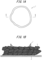
- the dot-like adhesive layers preferably have a crater-like uneven shape such as illustrated by a schematic plan view of one example of an adhesive layer 1 in FIG.
- FIG. 1A illustrates a case in which the adhesive layer 1 is formed on a negative electrode mixed material layer 3 on a current collector 2 in order to further facilitate understanding.
- the dot diameter per one adhesive layer is preferably 50 ⁇ m or more.
- a dot-like adhesive layer having a crater-like uneven shape can be formed by an inkjet method using a subsequently described coating machine, for example.
- the maximum thickness of the adhesive layer is preferably 2 ⁇ m or more. When the maximum thickness of the adhesive layer is 2 ⁇ m or more, adhesive strength between the electrode and the separator can be further increased. Note that the "maximum thickness of the adhesive layer" referred to in the present disclosure is the maximum value for thickness of the adhesive layer upon measurement of the adhesive layer using a laser microscope.
- the mass per unit area of the adhesive layer is preferably 0.02 g/m 2 or more, and is preferably 1.0 g/m 2 or less, and more preferably 0.5 g/m 2 or less.
- the mass per unit area of the adhesive layer is not less than the lower limit set forth above, the electrode and the separator can be sufficiently strongly adhered.
- the mass per unit area of the adhesive layer is not more than any of the upper limits set forth above, sufficiently high output characteristics of a secondary battery can be ensured.
- the "mass per unit area of the adhesive layer" referred to in the present disclosure can be determined from the mass difference per unit area between before supply of the composition for adhesion and after supply and drying of the composition for adhesion on the electrode or the separator.
- the ratio of coverage of the adhesive layer is preferably 1% or more, and more preferably 5% or more, and is preferably 50% or less, and more preferably 30% or less.
- the ratio of coverage of the adhesive layer is not less than any of the lower limits set forth above, the electrode and the separator can be more strongly adhered.
- the ratio of coverage of the adhesive layer is not more than any of the upper limits set forth above, sufficiently high output characteristics of a secondary battery can be ensured.
- ratio of coverage of the adhesive layer refers to the proportion occupied by area of a portion covered by the adhesive layer among the overall area of the electrode or the separator on which the adhesive layer is provided [i.e., (area of portion covered by adhesive layer/area of entire surface or region) ⁇ 100(%)].
- the laminate for a secondary battery set forth above can, for example, be efficiently produced by a production method according to one example described below.
- the laminate for a secondary battery is produced by implementing a step (A) of supplying the composition for adhesion described above to an affixing surface of at least one of the electrode and the separator, subsequently implementing a step (B) of conveying the electrode and the separator to an affixing start position without bringing another member into contact with the affixing surface to which the composition for adhesion has been supplied, and then further implementing a step (C) of affixing the electrode and the separator to each other via the affixing surface.
- affixing start position refers to a position at which an affixing surface of the electrode and an affixing surface of the separator come into contact when the electrode and the separator are being affixed to each other.
- the previously described composition for adhesion is supplied to an affixing surface of at least one of the electrode and the separator.
- the electrode that is used in production of the laminate for a secondary battery may be wound up in a roll form or may be pre-cut.
- the separator that is used in production of the laminate for a secondary battery may be wound up in a roll form or may be pre-cut. In particular, it is preferable that the separator is wound up in a roll form from a viewpoint of efficient continuous production of the laminate for a secondary battery.
- Supply of the composition for adhesion to the affixing surface can be performed by a method such as an inkjet method, a spraying method, a dispenser method, a gravure coating method, or a screen printing method without any specific limitations. Of these methods, an inkjet method is preferable for supply of the composition for adhesion from a viewpoint of high productivity and freedom of formation shape.
- the composition for adhesion is supplied to at least one of the electrode and the separator during supply of the composition for adhesion to the affixing surface.
- the electrode may be a positive electrode or may be a negative electrode.
- the composition for adhesion may be supplied to the entirety of the affixing surface or may be supplied to just part of the affixing surface.
- the composition for adhesion may be supplied such as to have any plan-view shape, such as a striped shape, a dotted shape, or a lattice shape without any specific limitations.
- supply of the composition for adhesion with a dotted shape is preferable from a viewpoint of increasing injectability of electrolyte solution in production of a secondary battery using the laminate for a secondary battery.
- the electrode and the separator are conveyed to an affixing start position without bringing another member into contact with the affixing surface to which the composition for adhesion has been supplied.
- the conveying of the electrode and the separator can be performed by any conveying mechanism such as a roller, a belt conveyor, a manipulator, or a suction band, for example, without any specific limitations.
- a roller a belt conveyor, a manipulator, or a suction band
- an affixing step of affixing the electrode and the separator to each other via the affixing surface and an optional cutting step that is described further below can be implemented.
- This affixing can be performed through pressing at normal temperature and/or heating, for example, of a laminate in which the electrode and the separator are overlapped with the affixing surface in-between, for example, but is not specifically limited to being performed in this manner.
- the time interval from completion of the step (A) to the start of the step (C) is preferably shorter than the time required for the composition for adhesion to completely dry. In other words, the composition for adhesion has preferably not completely dried at the point at which the step (C) starts. In a situation in which the step (C) can be started at a timing at which the composition for adhesion is not dried, the electrode and the separator can be more strongly adhered.
- the pressure applied to the laminate, the temperature during affixing of the electrode and the separator, and the time for which pressing and/or heating of the laminate is performed in the step (C) can be adjusted as appropriate depending on the amount of the composition for adhesion that is used, for example.
- the pressure during pressing of the laminate can be adjusted as appropriate depending on the used amount of the composition for adhesion, etc., but is preferably more than 1 MPa and not more than 5 MPa.
- Drying of the composition for adhesion can be performed using a heating device such as a heater, a dryer, or a heating roller without any specific limitations.
- the temperature during drying of the electrode and/or separator to which the composition for adhesion has been supplied is not specifically limited but is preferably 60°C or higher, more preferably 70°C or higher, and preferably 80°C or higher, and is preferably 100°C or lower.
- the temperature during drying is not lower than any of the lower limits set forth above, the electrode and the separator can be more strongly adhered, and battery performance of a secondary battery can be further improved.
- the adhesive layer is more easily formed, and productivity of the laminate for a non-aqueous secondary battery can be improved.
- the drying time is not specifically limited but is preferably not less than 0.1 seconds and not more than 120 seconds.
- the cutting step is a step of cutting the affixed body obtained in the affixing step to desired dimensions.
- the cutting can, for example, be performed using any cutting machine that can be used in the field of secondary battery production, such as a cutting machine that sandwiches and cuts an affixed body through cutting blades from both sides in a thickness direction of the affixed body.
- a feature of the presently disclosed non-aqueous secondary battery is that it includes the presently disclosed laminate for a non-aqueous secondary battery.
- the presently disclosed secondary battery has excellent battery characteristics such as output characteristics as a result of including the presently disclosed laminate for a secondary battery. No specific limitations are placed on the method by which the presently disclosed non-aqueous battery is produced.
- a step (assembly step) of assembling the secondary battery using the laminate for a secondary battery and an electrolyte solution is implemented in production of the secondary battery using the presently disclosed laminate for a secondary battery.
- the electrolyte solution is normally an organic electrolyte solution obtained by dissolving a supporting electrolyte in an organic solvent.
- a lithium salt is used as the supporting electrolyte in a case in which the secondary battery is a lithium ion secondary battery.
- lithium salts that can be used include LiPF 6 , LiAsF 6 , LiBF 4 , LiSbF 6 , LiAlCl 4 , LiClO 4 , CF 3 SO 3 Li, C 4 F 9 SO 3 Li, CF 3 COOLi, (CF 3 CO) 2 NLi, (CF 3 SO 2 ) 2 NLi, and (C 2 F 5 SO 2 )NLi.
- LiPF 6 LiClO 4 , and CF 3 SO 3 Li are preferable because they readily dissolve in solvents and exhibit a high degree of dissociation, with LiPF 6 being particularly preferable.
- One electrolyte may be used individually, or two or more electrolytes may be used in combination in a freely selected ratio.
- lithium ion conductivity tends to increase when a supporting electrolyte having a high degree of dissociation is used. Therefore, lithium ion conductivity can be adjusted through the type of supporting electrolyte that is used.
- the organic solvent used in the electrolyte solution is not specifically limited so long as the supporting electrolyte can dissolve therein.
- organic solvents that can suitably be used include carbonates such as dimethyl carbonate (DMC), ethylene carbonate (EC), diethyl carbonate (DEC), propylene carbonate (PC), butylene carbonate (BC), ethyl methyl carbonate (EMC), and vinylene carbonate (VC); esters such as ⁇ -butyrolactone and methyl formate; ethers such as 1,2-dimethoxyethane and tetrahydrofuran; and sulfur-containing compounds such as sulfolane and dimethyl sulfoxide. Furthermore, a mixture of such solvents may be used.
- lithium ion conductivity tends to increase when a solvent having a low viscosity is used. Therefore, lithium ion conductivity can be adjusted through the type of solvent that is used.
- the concentration of the electrolyte in the electrolyte solution can be adjusted as appropriate. Furthermore, known additives may be added to the electrolyte solution.
- the secondary battery can be assembled by further stacking an additional battery member (electrode and/or separator, etc.) with the presently disclosed laminate for a secondary battery, as necessary, subsequently performing rolling, folding, or the like of the resultant laminate in accordance with the battery shape, as necessary, to place the laminate in a battery container, injecting the electrolyte solution into the battery container, and sealing the battery container.
- an overcurrent preventing device such as a fuse or a PTC device; an expanded metal; or a lead plate may be provided as necessary.
- the shape of the secondary battery may be a coin type, button type, sheet type, cylinder type, prismatic type, flat type, or the like, for example.
- the proportion in the polymer constituted by a monomer unit that is formed through polymerization of a given monomer is normally, unless otherwise specified, the same as the ratio (charging ratio) of the given monomer among all monomers used in polymerization of the polymer.
- a water dispersion of a particulate polymer produced in each production example was dried at a temperature of 130°C for 1 hour to obtain a measurement sample.
- the measurement sample was weighed into an aluminum pan in an amount of 10 mg and was measured by a differential scanning calorimeter (EXSTAR DSC6220 produced by SII NanoTechnology Inc.) under conditions prescribed by JIS Z8703 with a measurement temperature range of -100°C to 500°C and a heating rate of 10°C/min to obtain a differential scanning calorimetry (DSC) curve.
- EXSTAR DSC6220 produced by SII NanoTechnology Inc.
- an intersection point of a baseline directly before a heat absorption peak on the DSC curve at which a derivative signal (DDSC) reached 0.05 mW/min/mg or more and a tangent to the DSC curve at a first inflection point to appear after the heat absorption peak was determined as the glass-transition temperature (°C).
- the volume-average particle diameter (D50) of a particulate polymer produced in each production example was measured by laser diffraction. Specifically, in a particle size distribution (by volume) obtained using a laser diffraction particle size analyzer (produced by Beckman Coulter, Inc.; product name: LS-13 320) with a water dispersion (solid content concentration: 0.1 mass%) containing the produced particulate polymer as a sample, the particle diameter at which cumulative volume calculated from a small diameter end of the distribution reached 50% was determined and was taken to be the volume-average particle diameter (D50) [nm].
- a water dispersion of a particulate polymer produced in each production example was dried, and approximately 0.2 g of the resultant dried product was pressed under pressing conditions of a temperature of 200°C and a pressure of 5 MPa for 2 minutes to obtain a film.
- the obtained film was cut to 1 cm-square to obtain a test specimen, and the mass W2 (g) of this test specimen was measured.
- the test specimen was immersed in electrolyte solution (solution obtained by dissolving LiPF 6 with a concentration of 1 mol/L in a mixed solvent of ethylene carbonate and diethyl carbonate (volume ratio: 3/7)) at a temperature of 60°C for 72 hours.
- the test specimen was subsequently removed from the electrolyte solution, mixed solvent on the surface of the test specimen was wiped off, and the mass W3 (g) of the test specimen was measured.
- a composition for adhesion produced in each example or comparative example was measured by laser diffraction. Specifically, in a particle size distribution (by volume) obtained using a laser diffraction particle size analyzer (produced by Beckman Coulter, Inc.; product name: LS-13 320) with a water dispersion (solid content concentration: 0.1 mass%) containing the produced composition for adhesion as a sample, the particle diameter at which cumulative volume calculated from a small diameter end of the distribution reached 50% was taken to be the particle size distribution (D50) [nm] of the composition for adhesion. Moreover, the particle diameter at which cumulative volume calculated from the small diameter end of this particle size distribution reached 90% was taken to be the particle size distribution (D90) [nm] of the composition for adhesion.
- D50 particle size distribution
- D90 particle size distribution
- a rheometer (MCR 502 produced by Anton Paar GmbH) was used to measure the viscosity ⁇ 0 at a shear rate of 100 s -1 and the viscosity ⁇ 1 at a shear rate of 10,000 s -1 at a temperature of 25°C. Values determined for the viscosity ⁇ 0 and viscosity ⁇ 1 were used to calculate a ratio ( ⁇ 0 / ⁇ 1 ) of the viscosity ⁇ 0 relative to the viscosity ⁇ 1 .
- An electrode (negative electrode or positive electrode) and a separator produced in each example or comparative example were observed using a laser displacement microscope (produced by Keyence Corporation; model: VK-X1000).
- An arbitrary 500 ⁇ m-square region was measured for each of the electrode and the separator, and the arithmetic average height was calculated.
- An average value for the arithmetic average height determined through measurement as described above for a total of 10 locations on the electrode or separator was taken to be the surface roughness (Sa) [ ⁇ m] of the electrode or the surface roughness (Sa) [ ⁇ m] of the separator.
- a composition for adhesion produced in each example or comparative example was supplied onto an electrode or separator that was the same as an electrode or separator used as a web 20A illustrated in FIG. 2 in each example or comparative example, and the composition for adhesion was dried under the same conditions as in each example or comparative example to form an adhesive layer.
- a laser microscope was used to measure the dot diameter of the adhesive layer and to observe the shape of the adhesive layer.
- the difference between the particle size distribution (D90) [ ⁇ m] of a composition for adhesion produced in each example or comparative example and the surface roughness (Sa) of an electrode (negative electrode or positive electrode) or a separator used as the web 20A illustrated in FIG. 2 in each example or comparative example was taken to be "D90 - Sa" [ ⁇ m].
- a composition for adhesion produced in each example or comparative example was supplied from an inkjet head of a KM1024 (shear-mode type) in an amount of 1,000 pL onto a polyethylene terephthalate (PET) substrate (surface roughness (Sa) ⁇ 0.1 ⁇ m; no release treatment).
- PET polyethylene terephthalate
- Sa surface roughness
- a laser displacement microscope (produced by Keyence Corporation; model: VK-X1000) was used to perform 3D height measurement for an arbitrary 500 ⁇ m-square region of the PET substrate.
- the position of a baseline of the PET substrate was taken as a reference, the volume of the composition for adhesion protruding further upward than this reference was calculated, and the determined volume was taken to be the remaining amount of coating liquid on the PET substrate.
- a composition for adhesion produced in each example or comparative example was supplied from an inkjet head of a KM1024 (shear-mode type) in an amount of 1,000 pL onto an electrode or separator that was the same as an electrode (negative electrode or positive electrode) or separator used as the web 20A illustrated in FIG. 2 in each example or comparative example.
- the volume of the composition for adhesion on the electrode (negative electrode or positive electrode) or separator was measured over time at normal temperature (25°C).
- the position of a baseline of the electrode (negative electrode or positive electrode) or separator was taken as a reference, the volume of the composition for adhesion protruding further upward than this reference was calculated by the same method as for "C(PET)" described above, and the determined volume was taken to be the remaining amount of coating liquid on the electrode (negative electrode or positive electrode) or separator.
- a composition for adhesion produced in each example or comparative example was supplied onto an electrode (negative electrode or positive electrode) that was the same as an electrode (negative electrode or positive electrode) used as the web 20A illustrated in FIG. 2 under the same conditions as in each example or comparative example.
- the electrode (negative electrode or positive electrode) onto which the composition for adhesion had been supplied and a separator that was the same as a separator used in each example or comparative example were pressed by pressing rolls (pressure bonding rollers 61 and 62 in FIG.
- the resultant laminate i.e., a laminate in which one electrode (negative electrode or positive electrode) and one separator were adhered via an adhesive layer
- a roll conveying roller 91 in FIG. 2 described further below
- Example 8 and 9 a composition for adhesion produced in Example 8 or 9 was supplied onto a separator that was the same as a separator used as the web 20A illustrated in FIG. 2 under the same conditions as in Example 8 or 9.
- the separator onto which the composition for adhesion had been supplied and a negative electrode that was the same as a negative electrode used in Example 8 or 9 were pressed by pressing rolls (pressure bonding rollers 61 and 62 in FIG.
- test specimens were placed with a surface at the current collector-side of the electrode facing downward, and cellophane tape was affixed to the surface at the current collector-side of the electrode. Tape prescribed by JIS Z1522 was used as the cellophane tape. Moreover, the cellophane tape was fixed to a horizontal test stage in advance. The stress when one end of the separator was pulled vertically upward at a pulling speed of 50 mm/min to peel off the separator was measured.
- a larger peel strength indicates higher adhesiveness between the electrode and the separator.
- a lithium ion secondary battery produced in each example or comparative example was fully charged to a state of charge (SOC) of 100% with a 1C constant current in an environment having a temperature of -10°C.
- SOC state of charge
- the fully charged secondary battery was disassembled, the negative electrode was removed, and the surface state of a negative electrode mixed material layer of the negative electrode was observed.
- An evaluation was made by the following standard. A lower lithium deposition rate on the negative electrode surface indicates that deposition of lithium on the negative electrode surface during charging is inhibited.
- a lithium ion secondary battery produced in each example or comparative example was constant-current constant-voltage (CCCV) charged to 4.3 V in an atmosphere having a temperature of 25°C for cell preparation.
- the prepared cell was discharged to 3.0 V by 0.2C and 1C constant-current methods in an atmosphere having a temperature of -10°C, and the electric capacity was determined for each thereof.
- a reactor including a stirrer was supplied with 100 parts of deionized water and 0.1 parts of ammonium persulfate, the gas phase was purged with nitrogen gas, and the temperature was raised to 80°C. Meanwhile, a monomer composition for core portion formation was obtained in a separate vessel by mixing 40 parts of deionized water, 0.2 parts of sodium dodecylbenzenesulfonate as an emulsifier, 28.3 parts of styrene as an aromatic monovinyl monomer, 66.6 parts of 2-ethylhexyl acrylate as a monofunctional (meth)acrylic acid ester monomer, 3 parts of methacrylic acid as an acidic group-containing monomer, and 0.1 parts of ethylene glycol dimethacrylate as a cross-linkable monomer.
- a monomer composition for shell portion formation containing 1.3 parts of styrene as an aromatic monovinyl monomer, 0.65 parts of butyl acrylate, and 0.05 parts of methacrylic acid as an acidic group-containing monomer was continuously supplied into this water dispersion over 60 minutes, and polymerization was continued. At the point at which the polymerization conversion rate reached 98%, cooling was performed to quench the reaction to produce a water dispersion containing a particulate polymer 1.
- the glass-transition temperature, volume-average particle diameter (D50), and degree of swelling of the obtained particulate polymer 1 were measured. The results are shown in Table 1.
- the particulate polymer 1 was confirmed to have a core-shell structure in which a shell portion partially covered an outer surface of a core portion through observation of cross-sectional structure of the particulate polymer 1 using a transmission electron microscope (TEM).
- TEM transmission electron microscope
- a reactor including a stirrer was supplied with 100 parts of deionized water and 0.3 parts of ammonium persulfate, the gas phase was purged with nitrogen gas, and the temperature was raised to 80°C. Meanwhile, a monomer composition for core portion formation was obtained in a separate vessel by mixing 40 parts of deionized water, 0.2 parts of sodium dodecylbenzenesulfonate as an emulsifier, 28.3 parts of styrene as an aromatic monovinyl monomer, 66.6 parts of 2-ethylhexyl acrylate as a monofunctional (meth)acrylic acid ester monomer, 3 parts of methacrylic acid as an acidic group-containing monomer, and 0.1 parts of ethylene glycol dimethacrylate as a cross-linkable monomer.
- This monomer composition for core portion formation was continuously added into the reactor over 3 hours, and a polymerization reaction was performed at a temperature of 80°C. Polymerization was continued until a polymerization conversion rate of 95% was reached to yield a water dispersion containing a particulate polymer forming a core portion.
- a monomer composition for shell portion formation containing 1.3 parts of styrene as an aromatic monovinyl monomer, 0.65 parts of butyl acrylate, and 0.05 parts of methacrylic acid as an acidic group-containing monomer was continuously supplied into the water dispersion over 60 minutes, and polymerization was continued. At the point at which the polymerization conversion rate reached 98%, cooling was performed to quench the reaction to produce a water dispersion containing a particulate polymer 2.
- the glass-transition temperature, volume-average particle diameter (D50), and degree of swelling of the obtained particulate polymer 2 were measured. The results are shown in Table 1.
- the particulate polymer 2 was confirmed to have a core-shell structure in which a shell portion partially covered an outer surface of a core portion through observation of cross-sectional structure of the particulate polymer 2 using a transmission electron microscope (TEM).
- TEM transmission electron microscope
- a water dispersion of a particulate polymer 3 having a core-shell structure was produced in the same way as in Production Example 2 with the exception that in production of the particulate polymer in Production Example 2, 0.02 parts of sodium dodecylbenzenesulfonate as an emulsifier was added into the reactor including a stirrer in addition to 100 parts of deionized water and 0.3 parts of ammonium persulfate.
- Various measurements were performed in the same way as in Production Example 1. The results are shown in Table 1.
- a reactor including a stirrer was supplied with 90 parts of deionized water and 0.5 parts of ammonium persulfate, the gas phase was purged with nitrogen gas, and the temperature was raised to 80°C. Meanwhile, a monomer composition was obtained in a separate vessel by mixing 15 parts of deionized water, 1.0 parts of NEOPELEX G15 (produced by Kao Corporation) as an emulsifier, 70.0 parts of 2-ethylhexyl acrylate as a monofunctional (meth)acrylic acid ester monomer, 25.0 parts of styrene as an aromatic monovinyl monomer, 1.7 parts of allyl glycidyl ether and 0.3 parts of allyl methacrylate as cross-linkable monomers, and 3.0 parts of acrylic acid as an acidic group-containing monomer.
- NEOPELEX G15 produced by Kao Corporation
- This monomer composition was continuously added into the reactor over 4 hours to perform polymerization.
- the reaction was performed at a temperature of 80°C during this continuous addition. Once the continuous addition was complete, a further 3 hours of stirring was performed at a temperature of 80°C, and then the reaction was ended.
- the resultant water dispersion was cooled to a temperature of 25°C and was subsequently adjusted to pH 8.0 through addition of sodium hydroxide aqueous solution. Thereafter, unreacted monomer was removed through introduction of steam to yield a water dispersion of a particulate polymer 4 that did not have a core-shell structure.
- Various measurements were performed in the same way as in Production Example 1. The results are shown in Table 1.
- a 5 MPa pressure-resistant vessel equipped with a stirrer was charged with 33 parts of 1,3-butadiene, 3.5 parts of itaconic acid, 63.5 parts of styrene, 0.4 parts of sodium dodecylbenzenesulfonate as an emulsifier, 150 parts of deionized water, and 0.5 parts of potassium persulfate as a polymerization initiator. These materials were thoroughly stirred and were then heated to a temperature of 50°C to initiate polymerization. At the point at which the polymerization conversion rate reached 96%, cooling was performed to quench the reaction to yield a mixture containing a binder (SBR) for a negative electrode mixed material layer.
- SBR binder
- the mixture containing the binder for a negative electrode mixed material layer was adjusted to pH 8 through addition of 5% sodium hydroxide aqueous solution and was then subjected to thermal-vacuum distillation to remove unreacted monomer. Thereafter, the mixture was cooled to a temperature of 30°C or lower to obtain a water dispersion containing the target binder for a negative electrode mixed material layer.
- Deionized water and 1.5 parts in terms of solid content of the water dispersion containing the binder for a negative electrode mixed material layer described above were added to the resultant mixture, the final solid content concentration was adjusted to 52%, and a further 10 minutes of mixing was performed.
- the resultant mixture was subjected to a defoaming process under reduced pressure to yield a slurry composition for a secondary battery negative electrode having good fluidity.
- the obtained slurry composition for a secondary battery negative electrode was applied onto both surfaces of copper foil of 20 ⁇ m in thickness serving as a current collector using a comma coater such as to have a thickness after drying of approximately 150 ⁇ m.
- the applied slurry composition was dried by conveying the copper foil inside an oven having a temperature of 60°C for 2 minutes at a speed of 0.5 m/min. Thereafter, 2 minutes of heat treatment was performed at a temperature of 120°C to obtain a pre-pressing negative electrode web.
- the pre-pressing negative electrode web was rolled by roll pressing to obtain the following four types of post-pressing negative electrode webs as post-pressing negative electrode webs.
- Negative electrode (1) web (negative electrode mixed material layer thickness: 95 ⁇ m; surface roughness (Sa): 0.5 ⁇ m)
- Negative electrode (2) web (negative electrode mixed material layer thickness: 88 ⁇ m; surface roughness (Sa): 0.3 ⁇ m)
- Negative electrode (3) web (negative electrode mixed material layer thickness: 100 ⁇ m; surface roughness (Sa): 0.8 ⁇ m)
- Negative electrode (4) web (negative electrode mixed material layer thickness: 103 ⁇ m; surface roughness (Sa): 1.0 ⁇ m)
- a slurry composition for a secondary battery positive electrode was obtained by mixing 100 parts of LiCoO 2 having a volume-average particle diameter of 12 ⁇ m as a positive electrode active material, 2 parts of acetylene black (produced by Denka Company Limited; product name: HS-100) as a conductive material, 2 parts in terms of solid content of polyvinylidene fluoride (produced by Kureha Corporation; product name: #7208) as a binder, and N-methylpyrrolidone as a solvent, adjusting these materials to a total solid content concentration of 70%, and mixing these materials using a planetary mixer.
- the obtained slurry composition for a secondary battery positive electrode was applied onto both surfaces of aluminum foil of 20 ⁇ m in thickness serving as a current collector using a comma coater such as to have a thickness after drying of approximately 150 ⁇ m.
- This applied slurry composition was dried by conveying the aluminum foil inside an oven having a temperature of 60°C for 2 minutes at a speed of 0.5 m/min. Thereafter, 2 minutes of heat treatment was performed at a temperature of 120°C to obtain a positive electrode web.
- the obtained positive electrode web was rolled by a roll press to obtain a post-pressing positive electrode web (surface roughness (Sa): 0.2 ⁇ m) including positive electrode mixed material layers.
- a separator web (ND412 (product name) produced by Asahi Kasei Corporation; surface roughness (Sa): 0.2 ⁇ m) made of polyethylene (PE) was prepared.
- the water dispersion of the particulate polymer 1 as a particulate polymer A having a core-shell structure and a volume-average particle diameter (D50) of 500 nm or more and the water dispersion of the particulate polymer 3 as a particulate polymer B having a core-shell structure and a volume-average particle diameter (D50) of less than 500 nm were compounded such that a mass ratio of amounts of solid content (particulate polymer A:particulate polymer B) was 20:80, the water dispersion of the particulate polymer 4 as a particulate polymer C not having a core-shell structure was further mixed therewith such that a mass ratio of amounts of solid content (total of particulate polymers A and B:particulate polymer C) was 100:10, and deionized water was further added to perform dilution to a solid content concentration of 10.5%. Propylene glycol was further added to the resultant mixture so as to adjust the solid content concentration to 10% and obtain
- composition for adhesion was used to measure and evaluate the particle size distribution of the composition for adhesion, slurry physical properties of the composition for adhesion, the shape of an adhesive layer, D90 - Sa, the remaining proportion of coating liquid, inkjet ejection characteristics, and adhesiveness between an electrode and a separator.
- the results are shown in Table 2.
- the produced composition for adhesion, negative electrode web, positive electrode web, and separator web were used to produce a laminate as illustrated in FIG. 2 .
- the negative electrode (1) web as a web 20A fed from a web roll was conveyed at a speed of 10 m/min while the composition for adhesion was supplied onto one surface of the web 20A from an inkjet head of an inkjet-type coating machine 52 (KM1024 (shear-mode type) produced by Konica) and a separator as a separator web 30A fed from a web roll was affixed to the web 20A by pressure bonding rollers 61 and 62.
- an inkjet-type coating machine 52 KM1024 (shear-mode type) produced by Konica
- composition for adhesion was also supplied onto the other surface of the web 20A from an inkjet head of an inkjet-type coating machine 51 (KM1024 (shear-mode type) produced by Konica), and a separator as a web 10A fed from a web roll was affixed to the laminate of the web 20A and the web 30A by pressure bonding rollers 61 and 62.
- composition for adhesion was also supplied onto a surface at the opposite side of the web 10A to the side corresponding to the web 20A from an inkjet head of an inkjet-type coating machine 53 (KM1024 (shear-mode type) produced by Konica), a positive electrode as a substrate that had been pre-cut was placed thereon, and then the substrate 40 was affixed to the laminate of the web 10A, the web 20A, and the web 30A by pressure bonding rollers 61 and 62.
- the composition for adhesion was supplied onto the substrate 40 from an inkjet head of an inkjet-type coating machine 54 (KM1024 (shear-mode type) produced by Konica), and then cutting was performed by a cutting machine 70 to obtain a laminate in which a separator, a negative electrode (1), a separator, and a positive electrode were stacked in this order.
- KM1024 shear-mode type
- an electrode mixed material layer (positive electrode mixed material layer or negative electrode mixed material layer) was not formed was provided at an edge part of the current collector of each of the substrate 40 and the web 20, punching was performed such that a tab of a desired size was formed in advance, and stacking was performed such that a positive electrode tab and a negative electrode tab were disposed at the same edge side of affixing surfaces X and Y (surface Z) of the electrodes and separators.
- the supplied composition for adhesion was dried by using heating rollers 92 for some of conveying rollers 91.
- the drying temperature was 90°C, and the drying time was 1 second.
- supply of the composition for adhesion from the inkjet heads was adjusted such that an adhesive layer obtained through drying of the adhesive layer composition was arranged in a dotted pattern and such that the dot diameter was 400 ⁇ m and the interval between dots was 400 ⁇ m pitch.
- An opening of the aluminum packing case was subsequently closed by heat sealing at a temperature of 150°C to produce a stacked lithium ion secondary battery having a capacity of 800 mAh.
- the obtained secondary battery was used to evaluate the lithium deposition rate on a negative electrode surface and output characteristics. The results are shown in Table 2.
- a composition for adhesion, a laminate, and a secondary battery were produced in the same way as in Example 1 with the exception that in production of the composition for adhesion, the mass ratio (particulate polymer A:particulate polymer B) of amounts of solid content of the particulate polymer A having a core-shell structure and the particulate polymer B having a core-shell structure was changed to 10:90.
- Various measurements and evaluations were performed in the same way as in Example 1. The results are shown in Table 2.
- a composition for adhesion, a laminate, and a secondary battery were produced in the same way as in Example 1 with the exception that in production of the composition for adhesion, the mass ratio (particulate polymer A:particulate polymer B) of amounts of solid content of the particulate polymer A having a core-shell structure and the particulate polymer B having a core-shell structure was changed to 30:70.
- Various measurements and evaluations were performed in the same way as in Example 1. The results are shown in Table 2.
- a composition for adhesion, a laminate, and a secondary battery were produced in the same way as in Example 1 with the exception that in production of the composition for adhesion, a particulate polymer B having a core-shell structure and a volume-average particle diameter (D50) of less than 500 nm was not used.
- D50 volume-average particle diameter
- a composition for adhesion, a laminate, and a secondary battery were produced in the same way as in Example 4 with the exception that in production of the composition for adhesion, the water dispersion of the particulate polymer 2 obtained in Production Example 2 was used as a particulate polymer A having a core-shell structure and a volume-average particle diameter (D50) of 500 nm or more.
- D50 volume-average particle diameter
- a composition for adhesion, a laminate, and a secondary battery were produced in the same way as in Example 2 with the exception that in production of the laminate, the negative electrode (2) web having a surface roughness (Sa) of 0.3 ⁇ m that was produced as previously described was used as the web 20A illustrated in FIG. 2 instead of the negative electrode (1) web having a surface roughness (Sa) of 0.5 ⁇ m.
- Various measurements and evaluations were performed in the same way as in Example 1. The results are shown in Table 3.
- a composition for adhesion and a secondary battery were produced in the same way as in Example 2 with the exception that in production of the secondary battery, a laminate produced as described below was used as a laminate.
- Various measurements and evaluations were performed in the same way as in Example 1. The results are shown in Table 3.
- a laminate having a separator, a positive electrode, a separator, and a negative electrode stacked in this order was obtained by performing operations in the same way as in Example 1 with the exception that in production of the laminate, the positive electrode web having a surface roughness (Sa) of 0.2 ⁇ m that was produced as previously described was used as the web 20A illustrated in FIG. 2 instead of the negative electrode (1) web having a surface roughness (Sa) of 0.5 ⁇ m, and a negative electrode (1) formed from the negative electrode (1) web was used as the substrate 40 instead of a positive electrode.
- a composition for adhesion and a secondary battery were produced in the same way as in Example 2 with the exception that in production of the secondary battery, a laminate produced as described below was used as a laminate.
- Various measurements and evaluations were performed in the same way as in Example 1. The results are shown in Table 3.
- a laminate in which a negative electrode (1), a separator, a positive electrode, and a separator were stacked in this order was obtained by performing operations in the same way as in Example 1 with the exception that in production of the laminate, the separator having a surface roughness (Sa) of 0.2 ⁇ m that was prepared as previously described was used as the web 20A illustrated in FIG. 2 instead of the negative electrode (1) web having a surface roughness (Sa) of 0.5 ⁇ m, the negative electrode (1) web produced as previously described was used as the web 30A instead of a separator, the positive electrode web produced as previously described was used as the web 10A instead of a separator, and the separator prepared as previously described was used as the substrate 40.
- the separator having a surface roughness (Sa) of 0.2 ⁇ m that was prepared as previously described was used as the web 20A illustrated in FIG. 2 instead of the negative electrode (1) web having a surface roughness (Sa) of 0.5 ⁇ m
- the negative electrode (1) web produced as previously described was used as the web 30
- a composition for adhesion, a laminate, and a secondary battery were produced in the same way as in Example 8 with the exception that in production of the laminate, the drying temperature of the supplied composition for adhesion was changed to 50°C.
- Various measurements and evaluations were performed in the same way as in Example 1. The results are shown in Table 3.
- a composition for adhesion, a laminate, and a secondary battery were produced in the same way as in Example 2 with the exception that in production of the laminate, the negative electrode (3) web having a surface roughness (Sa) of 0.8 ⁇ m that was produced as previously described was used as the web 20A illustrated in FIG. 2 instead of the negative electrode (1) web having a surface roughness (Sa) of 0.5 ⁇ m.
- Various measurements and evaluations were performed in the same way as in Example 1. The results are shown in Table 3.
- a composition for adhesion produced as described below was used as a composition for adhesion instead of the composition for adhesion used in Example 1.
- the negative electrode (4) web having a surface roughness (Sa) of 1.0 ⁇ m that was produced as previously described was used as the web 20A illustrated in FIG. 2 instead of the negative electrode (1) web having a surface roughness (Sa) of 0.5 ⁇ m.
- a laminate and a secondary battery were produced in the same way as in Example 1.
- Various measurements and evaluations were performed in the same way as in Example 1. The results are shown in Table 4.
- the water dispersion of the particulate polymer 3 as a particulate polymer having a core-shell structure and the particulate polymer 4 as a particulate polymer not having a core-shell structure were mixed such that a mass ratio of amounts of solid content (particulate polymer 3:particulate polymer 4) was 100:10 to yield a mixture containing the particulate polymers.
- this mixture was used, operations were performed in the same way as in Example 1 to obtain a composition for adhesion.
- a laminate and a secondary battery were produced in the same way as in Comparative Example 1 with the exception that a composition for adhesion produced as described below was used as a composition for adhesion instead of the composition for adhesion used in Example 1.
- Various measurements and evaluations were performed in the same way as in Example 1. The results are shown in Table 4.
- the water dispersion of the particulate polymer 3 as a particulate polymer A having a core-shell structure and the water dispersion of the particulate polymer 4 as a particulate polymer C not having a core-shell structure were mixed such that a mass ratio of amounts of solid content (particulate polymer A:particulate polymer C) was 100:10, a cellulose nanofiber water dispersion (WFo-1002 produced by Sugino Machine Limited) as a thixotropic agent was subsequently mixed therewith such that a mass ratio of amounts of solid content of the particulate polymer A and the thixotropic agent (particulate polymer A:thixotropic agent) was 100:0.1, and stirring was performed.
- deionized water was added so as to perform dilution to a solid content concentration of 10.5%.
- Propylene glycol was further added to the resultant mixture to adjust the solid content concentration to 10% and obtain a composition for adhesion.
- a composition for adhesion, a laminate, and a secondary battery were produced in the same way as in Comparative Example 2 with the exception that in production of the laminate, inkjet head adjustment was performed such that the dot diameter of an adhesive layer obtained through drying of the composition for adhesion was 180 ⁇ m.
- Various measurements were performed in the same way as in Example 1. The results are shown in Table 4.
- Example 1 Example 2
- Example 3 Example 4
- Laminate for non-aqueous secondary battery Composition adhesion for adhesion Particulate polymer having core-shell structure Particulate polymer A Particulate polymer 1 Particulate polymer 1 Particulate polymer 1 Particulate polymer 1 Particulate polymer 2
- Particulate polymer B Particulate polymer 3 Particulate polymer 3 Particulate polymer 3 - - Mass ratio of amounts of solid content (particulate polymer A:particulate polymer B) 20:80 10:90 30:70 - - Particulate polymer not having core-shell structure Particulate polymer C
- the laminates of Examples 1 to 10 have strong adhesion between an electrode and a separator and are capable of forming a secondary battery having excellent output characteristics.
- Table 4 that the laminate of Comparative Example 1 for which the remaining proportion of coating liquid is 0% and "D90 - Sa" is less than -0.25 does not have strong adhesion between an electrode and a separator and cannot form a secondary battery having excellent output characteristics.
- the laminates of Comparative Examples 2 and 3 for which the remaining proportion of coating liquid is 15% and "D90 - Sa" is less than -0.25 do not have strong adhesion between an electrode and a separator.
- a laminate for a non-aqueous secondary battery that has strong adhesion between an electrode and a separator and is capable of forming a non-aqueous secondary battery having excellent output characteristics.
- composition for adhesion that can suitably be used as a material forming an adhesive layer of the presently disclosed laminate for a non-aqueous secondary battery.
Landscapes
- Chemical & Material Sciences (AREA)
- Chemical Kinetics & Catalysis (AREA)
- Electrochemistry (AREA)
- General Chemical & Material Sciences (AREA)
- Engineering & Computer Science (AREA)
- Materials Engineering (AREA)
- Manufacturing & Machinery (AREA)
- Cell Separators (AREA)
- Secondary Cells (AREA)
Applications Claiming Priority (2)
| Application Number | Priority Date | Filing Date | Title |
|---|---|---|---|
| JP2021076625 | 2021-04-28 | ||
| PCT/JP2022/016947 WO2022230621A1 (ja) | 2021-04-28 | 2022-03-31 | 非水系二次電池用積層体、接着用組成物及び非水系二次電池 |
Publications (2)
| Publication Number | Publication Date |
|---|---|
| EP4333093A1 true EP4333093A1 (de) | 2024-03-06 |
| EP4333093A4 EP4333093A4 (de) | 2026-01-07 |
Family
ID=83848082
Family Applications (1)
| Application Number | Title | Priority Date | Filing Date |
|---|---|---|---|
| EP22795537.4A Pending EP4333093A4 (de) | 2021-04-28 | 2022-03-31 | Mehrschichtkörper für wasserfreie sekundärbatterien, verbindungszusammensetzung und wasserfreie sekundärbatterie |
Country Status (6)
| Country | Link |
|---|---|
| US (1) | US20240322374A1 (de) |
| EP (1) | EP4333093A4 (de) |
| JP (1) | JPWO2022230621A1 (de) |
| KR (1) | KR20240004328A (de) |
| CN (1) | CN117203844A (de) |
| WO (1) | WO2022230621A1 (de) |
Families Citing this family (6)
| Publication number | Priority date | Publication date | Assignee | Title |
|---|---|---|---|---|
| KR102573567B1 (ko) * | 2021-05-27 | 2023-09-04 | 더블유스코프코리아 주식회사 | 분리막 코팅 조성물 |
| WO2024116518A1 (ja) * | 2022-11-30 | 2024-06-06 | 日本ゼオン株式会社 | 非水系二次電池機能層用組成物、非水系二次電池用部材及びその製造方法、並びに非水系二次電池 |
| WO2024202962A1 (ja) * | 2023-03-27 | 2024-10-03 | 日本ゼオン株式会社 | 塗液、及び二次電池用の接着層の製造方法 |
| CN121816645A (zh) * | 2023-09-06 | 2026-04-07 | 株式会社村田制作所 | 二次电池 |
| CN120933437B (zh) * | 2025-10-11 | 2026-01-27 | 江苏正力新能电池技术股份有限公司 | 电极组件及其制备方法、电池单体、电池和用电装置 |
| CN121484075A (zh) * | 2026-01-12 | 2026-02-06 | 中创新航技术研究中心(深圳)有限公司 | 电池和用电装置 |
Family Cites Families (17)
| Publication number | Priority date | Publication date | Assignee | Title |
|---|---|---|---|---|
| JP5317130B2 (ja) * | 2010-08-30 | 2013-10-16 | 株式会社日立製作所 | 非水電解質電池用セパレータおよび非水電解質電池 |
| WO2012115096A1 (ja) | 2011-02-23 | 2012-08-30 | 日本ゼオン株式会社 | 二次電池用負極、二次電池、負極用スラリー組成物及び二次電池用負極の製造方法 |
| JP5617725B2 (ja) | 2011-03-28 | 2014-11-05 | 日本ゼオン株式会社 | 二次電池用電極、二次電池電極用バインダー、製造方法及び二次電池 |
| JP5652572B2 (ja) * | 2012-03-28 | 2015-01-14 | 日本ゼオン株式会社 | 二次電池用多孔膜及びその製造方法、二次電池用電極、二次電池用セパレーター並びに二次電池 |
| JPWO2013147006A1 (ja) * | 2012-03-30 | 2015-12-14 | 日本ゼオン株式会社 | 二次電池用多孔膜、二次電池用多孔膜スラリー、非導電性粒子、二次電池用電極、二次電池用セパレータ及び二次電池 |
| JP6186852B2 (ja) | 2013-04-30 | 2017-08-30 | 日本ゼオン株式会社 | 二次電池多孔膜用スラリー組成物、二次電池用電極、二次電池用セパレータおよび二次電池 |
| KR102604599B1 (ko) * | 2015-04-02 | 2023-11-22 | 에스케이이노베이션 주식회사 | 리튬 이차전지용 복합 분리막 및 이의 제조방법 |
| WO2016159720A1 (ko) * | 2015-04-02 | 2016-10-06 | 에스케이이노베이션 주식회사 | 리튬 이차전지용 복합 분리막 및 이의 제조방법 |
| KR102823305B1 (ko) * | 2015-10-28 | 2025-06-19 | 니폰 제온 가부시키가이샤 | 비수계 2차 전지 접착층용 조성물, 비수계 2차 전지용 접착층, 비수계 2차 전지용 접착층 부착 세퍼레이터, 비수계 2차 전지용 접착층 부착 전극, 그리고, 비수계 2차 전지 및 그 제조 방법 |
| JP6728653B2 (ja) * | 2015-11-30 | 2020-07-22 | 日本ゼオン株式会社 | 非水系二次電池およびその製造方法 |
| JP6723052B2 (ja) * | 2016-03-31 | 2020-07-15 | 旭化成株式会社 | 蓄電デバイス用セパレータ |
| CN110557970B (zh) * | 2017-04-26 | 2023-09-15 | 日本瑞翁株式会社 | 多孔膜用粘结剂组合物、多孔膜用浆料组合物、多孔膜以及非水系二次电池及其制造方法 |
| JP7103760B2 (ja) * | 2017-06-20 | 2022-07-20 | 旭化成株式会社 | パターン塗工用スラリー |
| EP3734695A4 (de) * | 2017-12-27 | 2021-11-17 | Zeon Corporation | Zusammensetzung für funktionsschichten einer wasserfreien sekundärbatterie, batterieelement für wasserfreie sekundärbatterien, verfahren zur herstellung eines laminats für wasserfreie sekundärbatterien sowie wasserfreie sekundärbatterie |
| KR20190128440A (ko) * | 2018-05-08 | 2019-11-18 | 삼성에스디아이 주식회사 | 리튬 이차 전지용 세퍼레이터, 이의 제조 방법 및 이를 포함하는 리튬 이차 전지 |
| KR102860686B1 (ko) | 2018-05-17 | 2025-09-15 | 니폰 제온 가부시키가이샤 | 비수계 이차 전지용 슬러리, 비수계 이차 전지용 세퍼레이터, 비수계 이차 전지용 전극, 비수계 이차 전지용 적층체 및 비수계 이차 전지 |
| WO2020045246A1 (ja) | 2018-08-29 | 2020-03-05 | 日本ゼオン株式会社 | 非水系二次電池接着層用組成物、非水系二次電池用電池部材およびその製造方法、並びに非水系二次電池用積層体の製造方法および非水系二次電池の製造方法 |
-
2022
- 2022-03-31 KR KR1020237035913A patent/KR20240004328A/ko active Pending
- 2022-03-31 WO PCT/JP2022/016947 patent/WO2022230621A1/ja not_active Ceased
- 2022-03-31 EP EP22795537.4A patent/EP4333093A4/de active Pending
- 2022-03-31 JP JP2023517227A patent/JPWO2022230621A1/ja active Pending
- 2022-03-31 US US18/554,790 patent/US20240322374A1/en active Pending
- 2022-03-31 CN CN202280029326.XA patent/CN117203844A/zh active Pending
Also Published As
| Publication number | Publication date |
|---|---|
| WO2022230621A1 (ja) | 2022-11-03 |
| JPWO2022230621A1 (de) | 2022-11-03 |
| US20240322374A1 (en) | 2024-09-26 |
| CN117203844A (zh) | 2023-12-08 |
| KR20240004328A (ko) | 2024-01-11 |
| EP4333093A4 (de) | 2026-01-07 |
Similar Documents
| Publication | Publication Date | Title |
|---|---|---|
| EP4333093A1 (de) | Mehrschichtkörper für wasserfreie sekundärbatterien, verbindungszusammensetzung und wasserfreie sekundärbatterie | |
| EP3852179B1 (de) | Laminierter körper für sekundärbatterien und sekundärbatterie und herstellungsverfahren dafür | |
| EP3796419A1 (de) | Aufschlämmung für wasserfreie sekundärbatterie, separator für eine wasserfreie sekundärbatterie, elektrode für eine wasserfreie sekundärbatterie, stapel für eine wasserfreie sekundärbatterie und wasserfreie sekundärbatterie | |
| EP3764449B1 (de) | Verfahren zur herstellung eines laminierten sekundärbatteriekörpers | |
| EP3734695A1 (de) | Zusammensetzung für funktionsschichten einer wasserfreien sekundärbatterie, batterieelement für wasserfreie sekundärbatterien, verfahren zur herstellung eines laminats für wasserfreie sekundärbatterien sowie wasserfreie sekundärbatterie | |
| US12062810B2 (en) | Secondary battery and method of producing same | |
| EP4333096A1 (de) | Zusammensetzung für haftschicht einer wasserfreien sekundärbatterie, haftschicht und verfahren zu ihrer herstellung | |
| EP4084172A1 (de) | Sekundärbatterie und herstellungsverfahren dafür | |
| EP4084171A1 (de) | Sekundärbatterie und herstellungsverfahren dafür | |
| EP3734697A1 (de) | Zusammensetzung für funktionsschichten einer wasserfreien sekundärbatterie, batterieelement für wasserfreie sekundärbatterien, verfahren zur herstellung eines laminats für wasserfreie sekundärbatterien sowie wasserfreie sekundärbatterie | |
| EP4318633A1 (de) | Zusammensetzung für wasserfreie sekundärbatterieklebeschichten, klebeschicht für wasserfreie sekundärbatterien und verfahren | |
| EP4398402A1 (de) | Zusammensetzung für haftschicht einer wasserfreien sekundärbatterie, haftschicht und verfahren zu ihrer herstellung | |
| EP4489206A1 (de) | Haftschichtzusammensetzung für wasserfreie sekundärbatterie, haftschicht für wasserfreie sekundärbatterie, laminat für wasserfreie sekundärbatterie | |
| EP4379835A1 (de) | Mehrschichtkörper für wasserfreie sekundärbatterien, verfahren zur herstellung eines mehrschichtkörpers für wasserfreie sekundärbatterien und wasserfreie sekundärbatterie | |
| EP4645566A1 (de) | Zusammensetzung für wasserfreie sekundärbatteriefunktionsschicht, element für wasserfreie sekundärbatterie, verfahren zur herstellung des elements für wasserfreie sekundärbatterie und wasserfreie sekundärbatterie |
Legal Events
| Date | Code | Title | Description |
|---|---|---|---|
| STAA | Information on the status of an ep patent application or granted ep patent |
Free format text: STATUS: THE INTERNATIONAL PUBLICATION HAS BEEN MADE |
|
| PUAI | Public reference made under article 153(3) epc to a published international application that has entered the european phase |
Free format text: ORIGINAL CODE: 0009012 |
|
| STAA | Information on the status of an ep patent application or granted ep patent |
Free format text: STATUS: REQUEST FOR EXAMINATION WAS MADE |
|
| 17P | Request for examination filed |
Effective date: 20231017 |
|
| AK | Designated contracting states |
Kind code of ref document: A1 Designated state(s): AL AT BE BG CH CY CZ DE DK EE ES FI FR GB GR HR HU IE IS IT LI LT LU LV MC MK MT NL NO PL PT RO RS SE SI SK SM TR |
|
| DAV | Request for validation of the european patent (deleted) | ||
| DAX | Request for extension of the european patent (deleted) | ||
| A4 | Supplementary search report drawn up and despatched |
Effective date: 20251205 |
|
| RIC1 | Information provided on ipc code assigned before grant |
Ipc: H01M 4/13 20100101AFI20251201BHEP Ipc: H01M 50/443 20210101ALI20251201BHEP Ipc: H01M 50/449 20210101ALI20251201BHEP Ipc: H01M 50/463 20210101ALI20251201BHEP Ipc: H01M 50/489 20210101ALI20251201BHEP |