EP4333128A1 - Stromkollektor und herstellungsverfahren dafür, negativelektrode und elektrochemische energiespeichervorrichtung - Google Patents
Stromkollektor und herstellungsverfahren dafür, negativelektrode und elektrochemische energiespeichervorrichtung Download PDFInfo
- Publication number
- EP4333128A1 EP4333128A1 EP22815219.5A EP22815219A EP4333128A1 EP 4333128 A1 EP4333128 A1 EP 4333128A1 EP 22815219 A EP22815219 A EP 22815219A EP 4333128 A1 EP4333128 A1 EP 4333128A1
- Authority
- EP
- European Patent Office
- Prior art keywords
- current collector
- polymer layer
- layer
- metal layer
- lithium
- Prior art date
- Legal status (The legal status is an assumption and is not a legal conclusion. Google has not performed a legal analysis and makes no representation as to the accuracy of the status listed.)
- Pending
Links
Images

Classifications
-
- H—ELECTRICITY
- H01—ELECTRIC ELEMENTS
- H01M—PROCESSES OR MEANS, e.g. BATTERIES, FOR THE DIRECT CONVERSION OF CHEMICAL ENERGY INTO ELECTRICAL ENERGY
- H01M4/00—Electrodes
- H01M4/02—Electrodes composed of, or comprising, active material
- H01M4/64—Carriers or collectors
- H01M4/66—Selection of materials
- H01M4/665—Composites
- H01M4/667—Composites in the form of layers, e.g. coatings
-
- H—ELECTRICITY
- H01—ELECTRIC ELEMENTS
- H01M—PROCESSES OR MEANS, e.g. BATTERIES, FOR THE DIRECT CONVERSION OF CHEMICAL ENERGY INTO ELECTRICAL ENERGY
- H01M4/00—Electrodes
- H01M4/02—Electrodes composed of, or comprising, active material
- H01M4/13—Electrodes for accumulators with non-aqueous electrolyte, e.g. for lithium-accumulators; Processes of manufacture thereof
-
- H—ELECTRICITY
- H01—ELECTRIC ELEMENTS
- H01M—PROCESSES OR MEANS, e.g. BATTERIES, FOR THE DIRECT CONVERSION OF CHEMICAL ENERGY INTO ELECTRICAL ENERGY
- H01M4/00—Electrodes
- H01M4/02—Electrodes composed of, or comprising, active material
- H01M4/64—Carriers or collectors
- H01M4/66—Selection of materials
-
- H—ELECTRICITY
- H01—ELECTRIC ELEMENTS
- H01M—PROCESSES OR MEANS, e.g. BATTERIES, FOR THE DIRECT CONVERSION OF CHEMICAL ENERGY INTO ELECTRICAL ENERGY
- H01M10/00—Secondary cells; Manufacture thereof
- H01M10/05—Accumulators with non-aqueous electrolyte
- H01M10/052—Li-accumulators
-
- H—ELECTRICITY
- H01—ELECTRIC ELEMENTS
- H01M—PROCESSES OR MEANS, e.g. BATTERIES, FOR THE DIRECT CONVERSION OF CHEMICAL ENERGY INTO ELECTRICAL ENERGY
- H01M10/00—Secondary cells; Manufacture thereof
- H01M10/60—Heating or cooling; Temperature control
- H01M10/65—Means for temperature control structurally associated with the cells
- H01M10/658—Means for temperature control structurally associated with the cells by thermal insulation or shielding
-
- H—ELECTRICITY
- H01—ELECTRIC ELEMENTS
- H01M—PROCESSES OR MEANS, e.g. BATTERIES, FOR THE DIRECT CONVERSION OF CHEMICAL ENERGY INTO ELECTRICAL ENERGY
- H01M4/00—Electrodes
- H01M4/02—Electrodes composed of, or comprising, active material
- H01M4/13—Electrodes for accumulators with non-aqueous electrolyte, e.g. for lithium-accumulators; Processes of manufacture thereof
- H01M4/134—Electrodes based on metals, Si or alloys
-
- H—ELECTRICITY
- H01—ELECTRIC ELEMENTS
- H01M—PROCESSES OR MEANS, e.g. BATTERIES, FOR THE DIRECT CONVERSION OF CHEMICAL ENERGY INTO ELECTRICAL ENERGY
- H01M4/00—Electrodes
- H01M4/02—Electrodes composed of, or comprising, active material
- H01M4/13—Electrodes for accumulators with non-aqueous electrolyte, e.g. for lithium-accumulators; Processes of manufacture thereof
- H01M4/139—Processes of manufacture
-
- H—ELECTRICITY
- H01—ELECTRIC ELEMENTS
- H01M—PROCESSES OR MEANS, e.g. BATTERIES, FOR THE DIRECT CONVERSION OF CHEMICAL ENERGY INTO ELECTRICAL ENERGY
- H01M4/00—Electrodes
- H01M4/02—Electrodes composed of, or comprising, active material
- H01M4/36—Selection of substances as active materials, active masses, active liquids
- H01M4/38—Selection of substances as active materials, active masses, active liquids of elements or alloys
- H01M4/40—Alloys based on alkali metals
- H01M4/405—Alloys based on lithium
-
- H—ELECTRICITY
- H01—ELECTRIC ELEMENTS
- H01M—PROCESSES OR MEANS, e.g. BATTERIES, FOR THE DIRECT CONVERSION OF CHEMICAL ENERGY INTO ELECTRICAL ENERGY
- H01M4/00—Electrodes
- H01M4/02—Electrodes composed of, or comprising, active material
- H01M4/64—Carriers or collectors
- H01M4/66—Selection of materials
- H01M4/661—Metal or alloys, e.g. alloy coatings
-
- H—ELECTRICITY
- H01—ELECTRIC ELEMENTS
- H01M—PROCESSES OR MEANS, e.g. BATTERIES, FOR THE DIRECT CONVERSION OF CHEMICAL ENERGY INTO ELECTRICAL ENERGY
- H01M4/00—Electrodes
- H01M4/02—Electrodes composed of, or comprising, active material
- H01M4/64—Carriers or collectors
- H01M4/66—Selection of materials
- H01M4/661—Metal or alloys, e.g. alloy coatings
- H01M4/662—Alloys
-
- H—ELECTRICITY
- H01—ELECTRIC ELEMENTS
- H01M—PROCESSES OR MEANS, e.g. BATTERIES, FOR THE DIRECT CONVERSION OF CHEMICAL ENERGY INTO ELECTRICAL ENERGY
- H01M4/00—Electrodes
- H01M4/02—Electrodes composed of, or comprising, active material
- H01M4/64—Carriers or collectors
- H01M4/66—Selection of materials
- H01M4/665—Composites
- H01M4/666—Composites in the form of mixed materials
-
- H—ELECTRICITY
- H01—ELECTRIC ELEMENTS
- H01M—PROCESSES OR MEANS, e.g. BATTERIES, FOR THE DIRECT CONVERSION OF CHEMICAL ENERGY INTO ELECTRICAL ENERGY
- H01M4/00—Electrodes
- H01M4/02—Electrodes composed of, or comprising, active material
- H01M4/64—Carriers or collectors
- H01M4/70—Carriers or collectors characterised by shape or form
- H01M4/72—Grids
- H01M4/74—Meshes or woven material; Expanded metal
- H01M4/742—Meshes or woven material; Expanded metal perforated material
-
- H—ELECTRICITY
- H01—ELECTRIC ELEMENTS
- H01M—PROCESSES OR MEANS, e.g. BATTERIES, FOR THE DIRECT CONVERSION OF CHEMICAL ENERGY INTO ELECTRICAL ENERGY
- H01M4/00—Electrodes
- H01M4/02—Electrodes composed of, or comprising, active material
- H01M4/64—Carriers or collectors
- H01M4/70—Carriers or collectors characterised by shape or form
- H01M4/80—Porous plates, e.g. sintered carriers
-
- H—ELECTRICITY
- H01—ELECTRIC ELEMENTS
- H01M—PROCESSES OR MEANS, e.g. BATTERIES, FOR THE DIRECT CONVERSION OF CHEMICAL ENERGY INTO ELECTRICAL ENERGY
- H01M4/00—Electrodes
- H01M4/02—Electrodes composed of, or comprising, active material
- H01M2004/021—Physical characteristics, e.g. porosity, surface area
-
- H—ELECTRICITY
- H01—ELECTRIC ELEMENTS
- H01M—PROCESSES OR MEANS, e.g. BATTERIES, FOR THE DIRECT CONVERSION OF CHEMICAL ENERGY INTO ELECTRICAL ENERGY
- H01M4/00—Electrodes
- H01M4/02—Electrodes composed of, or comprising, active material
- H01M2004/026—Electrodes composed of, or comprising, active material characterised by the polarity
- H01M2004/027—Negative electrodes
-
- Y—GENERAL TAGGING OF NEW TECHNOLOGICAL DEVELOPMENTS; GENERAL TAGGING OF CROSS-SECTIONAL TECHNOLOGIES SPANNING OVER SEVERAL SECTIONS OF THE IPC; TECHNICAL SUBJECTS COVERED BY FORMER USPC CROSS-REFERENCE ART COLLECTIONS [XRACs] AND DIGESTS
- Y02—TECHNOLOGIES OR APPLICATIONS FOR MITIGATION OR ADAPTATION AGAINST CLIMATE CHANGE
- Y02E—REDUCTION OF GREENHOUSE GAS [GHG] EMISSIONS, RELATED TO ENERGY GENERATION, TRANSMISSION OR DISTRIBUTION
- Y02E60/00—Enabling technologies; Technologies with a potential or indirect contribution to GHG emissions mitigation
- Y02E60/10—Energy storage using batteries
Definitions
- the present disclosure relates to the field of energy storage technologies, and more specifically, to a current collector, a preparation method therefor, a negative electrode, and an electrochemical energy storage device.
- Lithium batteries are characterized by high energy density, good cycle stability, safety, and the like, and are widely used in a number of fields such as mobile phones, computers, automobiles, and grid energy storage.
- a lithium foil used for a lithium metal battery brings high costs and a potential safety trouble in a battery manufacture process. Therefore, there is an inspiration that only a current collector is used as a negative electrode material, that is, a lithium metal battery made of theoretically zero-excess lithium has higher energy density theoretically.
- a current collector is used as a negative electrode material
- a lithium metal battery made of theoretically zero-excess lithium has higher energy density theoretically.
- lithium is deposited non-uniformly on the current collector, and generated dead lithium leads to low cycle life, and further generates severe lithium crystal dendrite to bring a potential safety trouble.
- use performance of the lithium battery is affected, and application of the lithium battery is limited.
- the present disclosure discloses a current collector, to alleviate and even resolve the foregoing problem of non-uniform lithium deposition, avoid generation of lithium crystal dendrite, and improve its use performance.
- the present disclosure provides a current collector.
- the current collector includes a first polymer layer, a metal layer, and a second polymer layer laminated sequentially, the current collector has with a number of through-holes that penetrate two opposite surfaces of the current collector in a lamination direction.
- the present disclosure provides a current collector, including: a first polymer layer; a metal layer, the metal layer being located on a side of the first polymer layer; and a second polymer layer, the second polymer layer being located on a side of the metal layer facing away from the first polymer layer; and in a direction from the first polymer layer to the second polymer layer, the current collector having with a number of through-holes that penetrate the current collector.
- the through-holes penetrate the current collector, which helps the current collector be effectively infiltrated by an electrolyte solution, to improve electrochemical consistency inside the current collector.
- the arrangement of the through-holes increases a specific surface area and internal spaces of the current collector, these internal spaces accommodate lithium precipitated in a charging/discharging process.
- the metal layer is disposed in the middle, and lithium may be induced to be deposited on the internal metal layer, to inhibit generation of lithium crystal dendrite, avoid generation of dead lithium (inactive lithium), and reduce interface impedance and loss of active lithium.
- the current collector provided in the present disclosure may be directly used as a negative electrode, to improve electrochemical performance and safety of the negative electrode.
- the current collector further includes a conductive layer, where the conductive layer is disposed on an inner side wall of the through-hole.
- the through-holes are distributed in an array form.
- An aperture size of the through-hole is less than or equal to 10 ⁇ m.
- a thickness of the metal layer is less than or equal to 4 ⁇ m.
- a thickness of the first polymer layer ranges from 11 ⁇ m to 26 ⁇ m.
- a thickness of the second polymer layer ranges from 11 ⁇ m to 26 ⁇ m.
- the current collector further includes a lithium-contained metal layer, and the lithium-contained metal layer is disposed in the metal layer.
- a thickness of the lithium-contained metal layer ranges from 10 nm to 2 ⁇ m.
- the current collector further includes a flame retardant layer, the flame retardant layer is disposed on a side of the first polymer layer facing away from the metal layer; and/or the flame retardant layer is disposed on a side of the second polymer layer facing away from the metal layer.
- a thickness of the flame retardant layer ranges from 10 nm to 1 ⁇ m.
- a lithium replenishment material is disposed in the first polymer layer, a weight percentage of the lithium replenishment material in the first polymer layer ranges from 0.1 wt% to 5 wt%, and the side of the first polymer layer facing away from the metal layer is insulating; and/or
- the present disclosure further provides a preparation method for a current collector.
- the method includes:
- the present disclosure further provides a negative electrode.
- the negative electrode includes the current collector according to the first aspect or the current collector prepared with the preparation method according to the second aspect.
- the present disclosure further provides an electrochemical energy storage device, including a positive electrode and the negative electrode according to the third aspect.
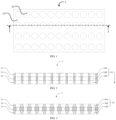
- FIG. 1 is a schematic top view of a current collector according to an implementation of the present disclosure
- FIG. 2 is a schematic cross-sectional view of FIG. 1 along a line I-I.
- the current collector 1 includes a first polymer layer 11, a metal layer 12, and a second polymer layer 13.
- the first polymer layer 11, the metal layer 12, and the second polymer layer 13 are sequentially laminated.
- the metal layer 12 is disposed on a side of the first polymer layer 11, and the second polymer layer 13 is disposed on a side of the metal layer 12 facing away from the first polymer layer 11.
- the current collector 1 has with a number of through-holes 14 that penetrate the current collector 1, that is to say, the current collected 1 has a number of through-holes 14 that penetrate two opposite surfaces of the current collector 1 in a lamination direction.
- the current collector 1 provided in the present disclosure has the through-holes 14 that penetrate the current collector 1, which helps the current collector 1 be effectively infiltrated by an electrolyte solution, to improve electrochemical consistency inside the current collector 1. Moreover, the arrangement of the through-holes 14 increases a specific surface area and internal spaces of the current collector 1, these internal spaces accommodate lithium precipitated in a charging/discharging process, to inhibit generation of lithium crystal dendrite.
- the metal layer 12 is disposed inside the current collector 1, and lithium may be induced to be deposited on the metal layer 12 inside the current collector 1, to inhibit generation of lithium crystal dendrite, avoid generation of dead lithium (inactive lithium), reduce interface impedance, avoid loss of active lithium, and improve electrochemical performance and use safety.
- the first polymer layer 11 and the second polymer layer 13 in the current collector 1 provided in the present disclosure, deposition of lithium on a surface of the current collector 1 is avoided, and use performance and safety performance of the current collector are effectively ensured.
- the arrangement of the through-holes 14 further improves the use performance of the current collector, and facilitates the application of the current collector.
- each of the first polymer layer 11, the metal layer 12, and the second polymer layer 13 is a porous layer structure.
- a material of the first polymer layer 11 may be selected from at least one of polyethylene, polypropylene, polyimide, polytetrafluoroethylene, polyvinylidene fluoride, polyester, and polyacrylonitrile. This is not limited in the present disclosure.
- a material of the second polymer layer 13 may be selected from at least one of polyethylene, polypropylene, polyimide, polytetrafluoroethylene, polyvinylidene fluoride, polyester, and polyacrylonitrile. This is not limited in the present disclosure.
- a material of the first polymer layer 11 is the same as that of the second polymer layer 13. Specifically, the material of the first polymer layer 11 and the material of the second polymer layer 13 may be but are not limited to polyethylene terephthalate.
- a thickness of the first polymer layer 11 ranges from 11 ⁇ m to 26 ⁇ m. To be specific, the thickness of the first polymer layer 11 ranges from 11 ⁇ m to 26 ⁇ m in the lamination direction. Further, a thickness of the first polymer layer 11 ranges from 15 ⁇ m to 23 ⁇ m. Specifically, the thickness of the first polymer layer 11 may be but is not limited to 11 ⁇ m, 13 ⁇ m, 15 ⁇ m, 18 ⁇ m, 21 ⁇ m, 25 ⁇ m, 26 ⁇ m, or the like. In some examples of the present disclosure, a thickness of the second polymer layer 13 ranges from 11 ⁇ m to 26 ⁇ m.
- the thickness of the second polymer layer 13 ranges from 11 ⁇ m to 26 ⁇ m in the lamination direction. Further, a thickness of the second polymer layer 13 ranges from 15 ⁇ m to 23 ⁇ m. Specifically, the thickness of the second polymer layer 13 may be but is not limited to 12 ⁇ m, 14 ⁇ m, 17 ⁇ m, 23 ⁇ m, 24 ⁇ m, or the like. In an embodiment, a thickness of the first polymer layer 11 is the same as that of the second polymer layer 13.
- the first polymer layer 11 and the second polymer layer 13 is provided with a lithium replenishment material. That is to say, the first polymer layer 11 and/or the second polymer layer 13 include the lithium replenishment material. Therefore, a supplement to consumed lithium is made in the charging/discharging process, to improve energy density and cycle life.
- the lithium replenishment material includes at least one of Li-Mg, Li-Al, Li-Si, Li-Ag, Li-Au, Li-Sn, Li-In, and Li-Ge alloys. Therefore, a supplement to lithium may be effectively made.
- a weight percentage of the lithium replenishment material in the first polymer layer 11 ranges from 0.1 wt% to 5 wt%.
- a weight percentage of the lithium replenishment material in the second polymer layer 13 ranges from 0.1 wt% to 5 wt%. Use of the lithium replenishment material with the foregoing content not only facilitates a supplement to lithium, but also does not affect insulation performance of the first polymer layer 11 or the second polymer layer 13.
- the weight percentage of the lithium replenishment material in the first polymer layer 11 may be but is not limited to 0.1 wt%, 0.5 wt%, 1 wt%, 2 wt%, 3 wt%, 4 wt%, or the like
- the weight percentage of the lithium replenishment material in the second polymer layer 13 may be but is not limited to 0.1 wt%, 0.5 wt%, 1 wt%, 2 wt%, 3 wt%, 4 wt%, or the like.
- the current collector when the current collector is provided with the lithium replenishment material, the current collector may meet at least one of the following conditions:
- a lithium replenishment material is disposed in the first polymer layer 11, and the side of the first polymer layer 11 facing away from the metal layer 12 is insulating.
- a lithium replenishment material is disposed in the second polymer layer 13, and the side of the second polymer layer 13 facing away from the metal layer 12 is insulating.
- the metal layer 12 disposed inside the current collector 1 ensures that lithium is preferentially deposited inside, avoids generation of lithium crystal dendrite, and facilitate an improvement in its electrochemical performance.
- a material of the metal layer 12 includes at least one of copper, gold, silver, magnesium, zinc, titanium, and nickel, or stainless steel. Further, a material of the metal layer 12 includes at least one of a copper simple substance, a copper alloy, silver, titanium, and nickel, or stainless steel. Specifically, the metal layer 12 may be but is not limited to a copper foil, a copper alloy foil, a stainless steel foil, a silver foil, a titanium foil, or a nickel foil. In an example, the metal layer 12 is a copper foil or a copper alloy foil.
- a thickness of the metal layer 12 is less than or equal to 4 ⁇ m.
- a thickness of the metal layer 12 is less than or equal to 4 ⁇ m in the lamination direction.
- a thickness of the metal layer 12 is less than or equal to 3 ⁇ m.
- the thickness of the metal layer 12 may be but is not limited to 0.5 ⁇ m, 1 ⁇ m, 1.5 ⁇ m, 2 ⁇ m, 3 ⁇ m, 4 ⁇ m, or the like.
- the thickness of the metal layer 12 is less than the thickness of the first polymer layer 11, and the thickness of the metal layer 12 is less than the thickness of the second polymer layer 13. Therefore, the percentage of the metal layer 12 in the whole current collector 1 is small, which can reduce weight and volume percentages of inactive components, and improve energy density of the current collector 1; and furthermore, the arrangement of the through-holes 14 does not excessively affect strength of the current collector, which facilitates an increase in the aperture size of the through-holes 14 and the porosity of the current collector 1.
- the thickness of the metal layer 12 is less than or equal to 4 ⁇ m
- the thickness of the first polymer layer 11 ranges from 11 ⁇ m to 26 ⁇ m
- the thickness of the second polymer layer 13 ranges from 11 ⁇ m to 26 ⁇ m.
- the current collector 1 has a number of through-holes 14, and the through-holes 14 penetrate two opposite surfaces of the current collector 1 in a lamination direction.
- a direction indicated by an arrow is a lamination direction.
- the through-holes 14 are distributed in an array form.
- the through-holes 14 are uniformly distributed in an array, to facilitate uniform deposition of lithium precipitated in a charging/discharging process, avoid protrusion of a part on which lithium is deposited excessively, and further improve use performance and safety performance.
- an aperture size of the through-hole 14 is less than or equal to 10 ⁇ m. Further, the aperture size of the through-hole 14 is less than 8 ⁇ m. Specifically, the aperture size of the through-hole 14 may be but is not limited to 3 ⁇ m, 4 ⁇ m, 5 ⁇ m, 6 ⁇ m, 8 ⁇ m, or the like.
- the arrangement of the through-holes 14 with the foregoing small aperture size further ensures that the electrolyte solution slowly passes through the through-holes 14, ensures that the current collector 1 is infiltrated in the electrolyte solution very well, and further improves consistency of electrochemical performance.
- the first polymer layer 11 has first sub-through-holes 141
- the metal layer 12 has second sub-through-holes 142
- the second polymer layer 13 has third sub-through-holes 143.
- a first sub-through-hole 141 is in communication with a third sub-through-hole 143 through a corresponding second sub-through-hole 142, to form a through-hole 14.
- each of the first sub-through-hole 141, the second sub-through-hole 142, and the third sub-through-hole 143 has an accommodating space inside, so that when the current collector 1 is infiltrated in the electrolyte solution, the electrolyte solution can infiltrate into the current collector 1 more uniformly, that is, inner surfaces of the first sub-through-hole 141, the second sub-through-hole 142, and the third sub-through-hole 143.
- an aperture shape of the through-hole 14 in the current collector 1 includes at least one of a cylinder, a cuboid tube, a cubic tube, a trapezoidal cylinder, and a triangular pyramid. Specifically, as long as the communication between the first sub-through-hole 141 and the third sub-through-hole 143 through the corresponding second sub-through-hole 142 is not affected, the aperture shape of the through-hole 14 is not limited in the present disclosure.
- a shape of a cross section of the through-hole 14 may be but is not limited to a polygon, a circle, an ellipse, an irregular shape, or the like
- a shape of a longitudinal section of the through-hole 14 may be but is not limited to a rectangle, a trapezoid, a quasi-trapezoid, a cone, a quasi-cone, an irregular shape, or the like.
- the cross section is a section of the through-hole along a plane on which the first or second polymer layer is disposed
- the longitudinal section is a section of the through-hole in a thickness direction of the current collector.
- the inner side wall of the through-hole 14 is in an oblique shape.
- the cross section of the through-hole 14 gradually increases in a direction from the metal layer 12 to the first polymer layer 11, and the cross section of the through-hole 14 gradually increases in a direction from the metal layer 12 to the second polymer layer 13.
- the through-hole may have a structure shown in FIG. 3 . That is to say, the section of the through-hole along the plane on which the first or second polymer layer is disposed gradually increases in the direction from the metal layer to the first polymer layer; or the section gradually increases in the direction from the metal layer to the second polymer layer.
- the foregoing section of the through-hole may meet one or two of the foregoing conditions.
- the aperture shape of the through-hole 14 is a cylinder.
- FIG. 3 is a schematic cross-sectional view of a current collector according to another implementation of the present disclosure.
- An aperture longitudinal section shape of the through-hole 14 is a quasi-trapezoid. In an example, when the through-hole 14 has a cross section that is circular and a longitudinal section that is quasi-trapezoidal, the through-hole 14 is in a shape of a trapezoidal cylinder.
- an aperture longitudinal section shape of the through-hole 14 is a quasi-trapezoid, the quasi-trapezoid includes two trapezoids whose short sides intersect each other, and the cross section of the through-hole 14 gradually increases from the metal layer 12 to two ends of the current collector 1.
- the cross sectional area of the second sub-through-hole 142 at the maximum size is less than or equal to the cross sectional area of the first sub-through-hole 141 and the third sub-through-hole 143 at the minimum size.
- FIG. 4 is a schematic cross-sectional view of a current collector according to another implementation of the present disclosure.
- the current collector 1 further includes a conductive layer 15, where the conductive layer 15 is disposed on an inner side wall of the through-hole 14. It may be understood that the disposed conductive layer 15 does not block the through-hole 14, and the inside of the current collector 1 still has a hollow-out space.
- the conductive layer 15 is disposed in the through-hole 14, so that metal lithium may be deposited in the internal space of the current collector 1, and is prevented from being deposited on the surface of the current collector 1, to effectively reduce formation of dead lithium and improve electrochemical performance.
- a conductive substance is deposited or impregnated on the inner side wall of the through-hole 14, to form the conductive layer 15. Further, the conductive substance is deposited on the inner side walls of the first sub-through-hole 141, the second sub-through-hole 142, and the third sub-through-hole 143, so that generation of by-products can be effectively reduced, thereby prolonging the service life of the current collector 1.
- the material of the conductive layer 15 includes at least one of a metal material, a carbon material, and a conductive polymer material. Specifically, the material of the conductive layer 15 includes at least one of gold, silver, copper, nickel, iron, aluminum, germanium, tin, zinc, indium, vanadium, magnesium, cobalt, carbon, polyaniline, and polypyrrole.
- FIG. 5 is a schematic cross-sectional view of a current collector according to another implementation of the present disclosure.
- the current collector 1 further includes a lithium-contained metal layer 16, and the lithium-contained metal layer 16 is disposed in the metal layer 12.
- a material of the lithium-contained metal layer 16 may include at least one of a lithium simple substance and a lithium alloy.
- the lithium alloy includes at least one of Li-Ag, Li-Mg, Li-Zn, Li-Al, Li-Au, Li-Si, Li-Sn, and Li-Ge alloys.
- a thickness of the lithium-contained metal layer 16 ranges from 10 nm to 2 ⁇ m. Further, a thickness of the lithium-contained metal layer 16 ranges from 100 nm to 1.5 ⁇ m. Furthermore, a thickness of the lithium-contained metal layer 16 ranges from 300 nm to 1000 nm. Specifically, a thickness of the lithium-contained metal layer 16 may be but is not limited to 100 nm, 400 nm, 500 nm, 800 nm, 1 ⁇ m, 1.5 ⁇ m, 1.8 ⁇ m, 2 ⁇ m, or the like. In an implementation, the lithium-contained metal layer 16 is disposed inside the metal layer 12. That is to say, the lithium-contained metal layer 16 is wrapped in the metal layer 12.
- the metal layer 12 includes a first porous metal layer and a second porous metal layer, and the first porous metal layer, the lithium-contained metal layer 16, and the second porous metal layer are sequentially laminated. It should be noted that, the through-holes 14 similarly penetrate the flame retardant layer and the lithium-contained metal layer 16.
- FIG. 6 is a schematic cross-sectional view of a current collector according to another implementation of the present disclosure.
- the current collector 1 further includes a flame retardant layer 17, and the flame retardant layer 17 is disposed in at least one of the following positions: the flame retardant layer 17 is disposed on a side of the first polymer layer 11 facing away from the metal layer 12, and the flame retardant layer 17 is disposed on a side of the second polymer layer 13 facing away from the metal layer 12.
- the flame retardant layer 17 is disposed on a side of the first polymer layer 11 facing away from the metal layer 12, and/or the flame retardant layer 17 is disposed on a side of the second polymer layer 13 facing away from the metal layer 12.
- the current collector 1 When the current collector 1 is used in an electrochemical energy storage device 2, metal lithium is highly active. As a result, when short-circuiting occurs, it is easy to burn the electrochemical energy storage device 2, to cause a safety accident.
- the flame retardant layer 17 By arranging the flame retardant layer 17, at the beginning of short-circuiting, the flame retardant layer 17 may be heated and melted, and may block the holes and wrap metal lithium deposited in the through-holes 14, to prevent further contact between the metal lithium and the electrolyte solution from triggering thermal runaway.
- the melted flame retardant layer 17 may block the first sub-through-hole 141 in the adjacent first polymer layer 11 and/or the second sub-through-hole 142 in the adjacent second polymer layer 13, to isolate ion channels, eliminate the potential safety trouble, and improve use safety.
- a melting point of the material of the flame retardant layer 17 ranges from 120°C to 155°C. Use of the flame retardant material with a low melting point better helps perform flame retardation. It should be noted that, when the flame retardant layer 17 is disposed on a side of the first polymer layer 11 facing away from the metal layer 12, and/or on a side of the second polymer layer 13 facing away from the metal layer 12, the through-holes 14 similarly penetrate the flame retardant layer 17.
- the material of the flame retardant layer 17 includes one or more of polyethylene wax, polypropylene wax, and polyethylene oxide wax.
- the flame retardant layer 17 has a small thickness, whose thickness range may be but is not limited to 10 nm to 1 ⁇ m, 50 nm to 0.8 ⁇ m, 100 nm to 0.7 ⁇ m, 200 nm to 0.5 ⁇ m, or the like.
- a specific preparation method for the current collector 1 is not specially limited in the present disclosure. Next, an example is used to describe a preparation method for the current collector 1 provided in the present disclosure.
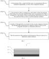
- FIG. 7 is a schematic flowchart of preparing a current collector according to an implementation of the present disclosure.
- a preparation method for the current collector 1 includes: steps S701, S702, S703, and S704. Steps S701, S702, S703, and S704 are described in detail as follows:
- S701 A first polymer film, a metal film, and a second polymer film are laminated sequentially, to form a first composite structure.
- the laminating a first polymer film, a metal film, and a second polymer film sequentially includes: depositing metal on the first polymer film, to form the metal film; and then forming the second polymer film on the metal film through at least one of a liquid-phase coating technique, an atom deposition technique, and a melt extrusion and calendering technique.
- the laminating a first polymer film, a metal film, and a second polymer film sequentially includes: providing a substrate, depositing metal on the substrate, and performing exfoliation to form the metal film; and then forming the first polymer film and the second polymer film on two opposite surfaces of the metal film through at least one of a liquid-phase coating technique, an atom deposition technique, and a melt extrusion and calendering technique.
- deposition may be performed through, but not limited to, magnetron sputtering, ion plating, vacuum evaporation, or the like.
- technical parameters of deposition may be selected as required, and this is not limited in the present disclosure.
- the laminating a first polymer film, a metal film, and a second polymer film sequentially includes: mounting the first polymer film into a vacuum magnetron sputtering coating machine, performing vacuumization with a vacuum pump to make a vacuum degree of a cavity reach 8 ⁇ 10 -2 Pa, then feeding some argon to perform adjustment to make the vacuum degree reach 2 ⁇ 10 -1 Pa, performing surface ion source cleaning on the first polymer film for a cleaning time ranging from 5 min to 15 min, and switching off an ion source power supply after the cleaning is completed; and starting a metal plating power supply to perform magnetron sputtering on the metal film, where the sputtering is performed on the metal film for a time ranging from 5 min to 100 min, to obtain the metal film whose thickness is less than or equal to 4 ⁇ m.
- a first protective film is disposed on a side surface of the first polymer film facing away from the metal film, and a second protective film is disposed on a side surface of the second polymer film facing away from the metal film, to form a second composite structure.
- the protective film may be but is not limited to at least one of a transparent tape, an engineering paper, and a preservative film.
- S703 A number of through-holes are formed on the second composite structure, the through-holes penetrating two opposite surfaces of the second composite structure in a lamination direction.
- a number of first sub-through-holes 141 are formed on the first polymer film, to form the first polymer layer 11
- a number of second sub-through-holes 142 are formed on the metal film, to form the metal layer 12
- a number of third sub-through-holes 143 are formed on the second polymer film, to form the second polymer layer 13.
- a number of through-holes are formed on the second composite structure through ultrafast laser.
- the preparation method for the current collector 1 further includes: depositing a conductive substance on the inner side wall of the through-hole 14, to form the conductive layer 15.
- the conductive substance may be disposed on the inner side wall of the through-hole 14, for example, disposed on the inner side walls of the first sub-through-hole 141, the second sub-through-hole 142, and the third sub-through-hole 143, to form the conductive layer 15.
- the conductive substance may be controlled to be partially deposited on the inner side walls of the first sub-through-hole 141, the second sub-through-hole 142, and the third sub-through-hole 143, to prevent the conductive substance from blocking the through-holes 14 due to an excessively long deposition time.
- the present disclosure further provides a negative electrode 22.
- the negative electrode 22 includes the current collector 1 in any one of the foregoing implementations. Specifically, for the current collector 1, reference is made to the above description. Details are not described herein again.
- the current collector 1 may be directly as the negative electrode 22, and the negative electrode 22 does not need to be provided with a negative electrode active material layer.
- the negative electrode 22 is a lithium-free negative electrode, and when the current collector 1 provided in the present disclosure is used as the negative electrode 22, electrochemical performance and safety performance of the negative electrode 22 can be greatly improved.
- the present disclosure further provides an electrochemical energy storage device 2.
- the electrochemical energy storage device 2 includes the negative electrode 22 described above.
- FIG. 8 is a schematic cross-sectional view of an electrochemical energy storage device according to an implementation of the present disclosure.
- the electrochemical energy storage device 2 includes a positive electrode 21 and a negative electrode 22.
- the current collector 1 is used as the negative electrode 22 of the electrochemical energy storage device 2.
- the electrochemical energy storage device 2 is a lithium-free negative electrode-lithium battery, that is, a negative electrode-free battery.
- the electrochemical energy storage device 2 may alternatively be another type of battery. This is not limited in the present disclosure.
- the electrochemical energy storage device 2 includes a positive electrode 21 and a negative electrode 22, and the current collector 1 is used as the negative electrode 22 of the electrochemical energy storage device 2.
- the porosity ⁇ of the current collector 1 refers to a percentage of a total volume of the through-holes 14 in a total volume of the current collector 1
- the areal capacity of the positive electrode 21 refers to a total quantity of electrons that the positive electrode 21 of the electrochemical energy storage device 2 can release per unit surface area.
- a high porosity can ensure that when the thickness of the current collector 1 is small, a space requirement for lithium deposition can be further met, to avoid volume expansion caused by unordered lithium deposition, and improve safety performance of the current collector 1. Further, ⁇ 60%, and C>6 mAh/cm 2 .
- the positive electrode 21 includes a positive electrode current collector and a positive electrode active material layer.
- a material of the positive electrode active material layer includes at least one of LiAl 0.05 Co 0.15 Ni 0.80 O 2 , LiNi 0.80 Co 0.10 Mn 0.10 O 2 , LiNi 0.90 Co 0.05 Mn 0.05 O 2 , LiNi 0.60 Co 0.20 Mn 0.20 O 2 , LiCoO 2 , LiMn 2 O 4 , LiFePO 4 , LiMnPO 4 , LiNiPO 4 , LiCoPO 4 , LiNi 0.5 Mn 1.5 O 4 , and Li 3 V 3 (PO 4 ) 3 .
- a material of the positive electrode active material layer includes at least one of lithium sulfide, lithium-inserted state V 2 O 5 , lithium-inserted state MnO 2 , lithium-inserted state TiS 2 , and lithium-inserted state FeS 2 .
- the electrochemical energy storage device 2 further includes a separator film 23 disposed between the positive electrode 21 and the negative electrode 22.
- the separator film 23 is configured to separate the positive electrode 21 and the negative electrode 22 of the electrochemical energy storage device 2, and a material of the separator film 23 is not limited in the present disclosure.
- the current collector enables the electrochemical energy storage device 2 to have large energy density, high charging/discharging capacity, insusceptibility to generation of lithium crystal dendrite, high safety performance, and long cycle life.
- a preparation method for a current collector includes:
- a preparation method for a current collector includes: Approximately the same as Embodiment 1. A difference lies in that the first PET film and the second PET film have a thickness of 16.75 ⁇ m, the porosity and the size of the through-holes are 80% and 10 ⁇ m respectively, and a current collector Z2 is obtained.
- a preparation method for a current collector includes: Approximately the same as Embodiment 1. A difference lies in that the first PET film and the second PET film have a thickness of 28 ⁇ m, the porosity and the aperture size of the through-holes are 50% and 5 ⁇ m respectively, and a current collector Z3 is obtained.
- a preparation method for a current collector includes: Approximately the same as Embodiment 1. A difference lies in that the transparent tape protective film is directly removed after step (3) without performing step (4), and a current collector Z4 is obtained.
- a preparation method for a current collector includes: Approximately the same as Embodiment 1. A difference lies in that a number of through-holes are disposed in an unordered manner, and a current collector Z5 is obtained.
- a preparation method for a current collector includes: Approximately the same as Embodiment 1. A difference lies in that the metal copper foil has a thickness of 8 ⁇ m, the first PET film and the second PET film have a thickness of 16 ⁇ m, and a current collector Z6 is obtained.
- a preparation method for a current collector includes: Approximately the same as Embodiment 1. A difference lies in that the porosity and the aperture size of the through-holes are 50% and 10 ⁇ m respectively, and a current collector Z7 is obtained.
- a preparation method for a current collector includes: Approximately the same as Embodiment 1. A difference lies in that a surface of the first PET film facing away from the metal copper foil and a surface of the second PET film facing away from the metal copper foil are each provided with a porous polypropylene wax flame retardant layer, and a current collector Z8 is obtained.
- a preparation method for a current collector includes: Approximately the same as Embodiment 1. A difference lies in that magnesium aluminum alloy particles are disposed in the second PET film, a weight percentage of the magnesium aluminum alloy particles in the second PET film is 1 wt%, the surface of the second PET film is insulating, and a current collector Z9 is obtained.
- a preparation method for a current collector includes: Approximately the same as Embodiment 1. A difference lies in that the porosity and the aperture size of the through-holes are 80% and 10 ⁇ m respectively, and a current collector Z10 is obtained.
- step (4) exfoliation is first performed to remove the transparent tape protective film on the surface and then the same evaporation process is performed, and a current collector DZ1 is obtained.
- Embodiment 1 Approximately the same as Embodiment 1. A difference lies in that a treatment time for each time of laser pore-forming in step (3) is halved, a porous structure in an array of non-through-holes is obtained, and the aperture size of the through-holes are 10 ⁇ m. Because of the non-through-holes, the porosity is 67.5%, and a current collector DZ2 is obtained.
- a charging/discharging cycle test is performed on each of the batteries at 0.2 C under a condition of 25°C. Steps are as follows: Standing lasts for 10 min; the battery is charged at a constant current of 0.2 C to 3.8 V, and charged at a constant voltage of 3.8 V to 0.05 C; Standing lasts for 10 min; the battery is discharged at 0.5 C to 2.7 V, which is one cycle. The steps are repeated.
- Table 1 Table of data of average initial discharging capacity of the battery and a change rate of thicknesses of the battery before and after the cycle Serial No.
- Impedance (EIS) test For each of S1-S10 and DS1-DS2, two batteries are additionally taken and are filled with a liquid and then stand, an impedance test (with an amplitude of 5 mV and a frequency of 1000-0.01 Hz) is performed on each battery every 0.5 h, and experimental results are shown in Table 2.
- Energy density evaluation is performed according to the experimental results in Table 1, and experimental results are shown in Table 3.
- Specific energy (initial discharging capacity * average initial discharging voltage)/battery weight
- volumetric energy density (n th discharging capacity * average n th discharging voltage)/battery volume
- the foregoing battery weight is cell weight excluding a housing, a cover plate, and components disposed on the housing and the cover plate
- the foregoing battery volume is cell volume excluding the housing, the cover plate, and the components disposed on the housing and the cover plate.
- Table 3 Table of battery energy density evaluation Energy density Specific energy Wh/kg Volumetric energy density - Wh/L Cycle count 0 0 20 50 100 150 200 Embodiment 1 324.28 664.8 645.2 615.8 568.9 520.7 455.8 Embodiment 2 328.48 671.8 651.1 621.6 592.5 532.8 475.2 Embodiment 3 318.10 614.3 595.6 563.5 509.5 466.7 404.8 Embodiment 4 324.27 661.5 637.2 596.3 530.2 485.6 400.5 Embodiment 5 322.98 662.2 638.3 600.7 535.9 494.1 408.9 Embodiment 6 308.69 664.5 642.6 609.5 553.8 503.8 438.7 Embodiment 7 319.21 657.7 628.8 583.9 510.2 451.8 387.5 Embodiment 8 319.18 660.9 639.5 603.8 550.7 498.6 428.5 Embodiment 9 314.74 664.6 645.7 615.6 568.
- Table 4 Table of lithium deposition positions of batteries 0.6 mA/cm 2 Shape Thickness change/ ⁇ m Embodiment 1 Compact circle or ellipse, with no lithium deposited on the surface 0.1 Embodiment 2 Compact circle or ellipse, with no lithium deposited on the surface 0.1 Embodiment 3 Compact circle or ellipse, with no lithium deposited on the surface 0.1 Embodiment 4 Compact circle or ellipse, with no lithium deposited on the surface 0.8 Embodiment 5 Compact circle or ellipse, with no lithium deposited on the surface 1.1 Embodiment 6 Compact circle or ellipse, with no lithium deposited on the surface 0.2 Embodiment 7 Compact circle or ellipse, with a small amount of lithium deposited on the surface 3.8 Embodiment 8 Compact circle or ellipse, with no lithium deposited on the surface 0.2 Embodiment 9 Compact circle or ellipse, with no lithium deposited on the surface 0.2 Embodiment 10 Compact circle
- the comparative examples have specific energy and volumetric energy density basically equivalent to those of the embodiments initially, but in the comparative examples, lithium metal is prone to be deposited on the surface of the negative electrode, capacity attenuation is fast after the cycle, battery volume expansion is large, and volumetric energy density is lowest at the later stage of the cycle.
- the battery provided in the embodiments of the present disclosure includes the current collector provided in the present disclosure, so that the battery has large energy density, high charging/discharging capacity, insusceptibility to generation of lithium crystal dendrite, high safety performance, and long cycle life.
Landscapes
- Chemical & Material Sciences (AREA)
- Chemical Kinetics & Catalysis (AREA)
- Electrochemistry (AREA)
- General Chemical & Material Sciences (AREA)
- Engineering & Computer Science (AREA)
- Materials Engineering (AREA)
- Manufacturing & Machinery (AREA)
- Composite Materials (AREA)
- Cell Electrode Carriers And Collectors (AREA)
- Battery Electrode And Active Subsutance (AREA)
Applications Claiming Priority (2)
| Application Number | Priority Date | Filing Date | Title |
|---|---|---|---|
| CN202110610629.8A CN115440987B (zh) | 2021-06-01 | 2021-06-01 | 集流体及其制备方法、负极和电化学储能装置 |
| PCT/CN2022/095943 WO2022253174A1 (zh) | 2021-06-01 | 2022-05-30 | 集流体及制备的方法、负极和电化学储能装置 |
Publications (2)
| Publication Number | Publication Date |
|---|---|
| EP4333128A1 true EP4333128A1 (de) | 2024-03-06 |
| EP4333128A4 EP4333128A4 (de) | 2025-08-06 |
Family
ID=84271736
Family Applications (1)
| Application Number | Title | Priority Date | Filing Date |
|---|---|---|---|
| EP22815219.5A Pending EP4333128A4 (de) | 2021-06-01 | 2022-05-30 | Stromkollektor und herstellungsverfahren dafür, negativelektrode und elektrochemische energiespeichervorrichtung |
Country Status (6)
| Country | Link |
|---|---|
| US (1) | US20240105962A1 (de) |
| EP (1) | EP4333128A4 (de) |
| JP (1) | JP7769727B2 (de) |
| CN (1) | CN115440987B (de) |
| CA (1) | CA3220863A1 (de) |
| WO (1) | WO2022253174A1 (de) |
Families Citing this family (5)
| Publication number | Priority date | Publication date | Assignee | Title |
|---|---|---|---|---|
| KR20240098936A (ko) * | 2022-12-21 | 2024-06-28 | 주식회사 엘지에너지솔루션 | 무음극 전지 |
| CN116203441B (zh) * | 2023-03-24 | 2023-10-27 | 广州巨湾技研有限公司 | 锂离子电池温熵系数的测试方法及装置 |
| CN116417621B (zh) * | 2023-06-12 | 2023-09-05 | 广州方邦电子股份有限公司 | 一种复合箔材、电池极片与电池 |
| CN120432493A (zh) * | 2024-02-02 | 2025-08-05 | 宁德时代新能源科技股份有限公司 | 电极极片及其制备方法、电池和用电装置 |
| CN120033420B (zh) * | 2025-04-23 | 2025-07-25 | 江苏时代新能源科技有限公司 | 复合隔离膜、二次电池以及用电装置 |
Family Cites Families (22)
| Publication number | Priority date | Publication date | Assignee | Title |
|---|---|---|---|---|
| JP5681351B2 (ja) * | 2009-06-19 | 2015-03-04 | 旭化成株式会社 | 電極集電体及びその製造方法、電極並びに蓄電素子 |
| JP2014096314A (ja) * | 2012-11-12 | 2014-05-22 | Seiko Epson Corp | リチウムイオン二次電池用集電体の製造方法、リチウムイオン二次電池用集電体、電極体およびリチウムイオン二次電池 |
| JP6199416B2 (ja) | 2014-01-31 | 2017-09-20 | 富士フイルム株式会社 | アルミニウム板の製造方法、アルミニウム板、蓄電デバイス用集電体、蓄電デバイス、防音・吸音材、電磁波シールドおよび建築用材料 |
| CN107075714A (zh) | 2014-09-30 | 2017-08-18 | 富士胶片株式会社 | 铝板 |
| JP2015213180A (ja) * | 2015-06-16 | 2015-11-26 | 東洋アルミニウム株式会社 | 負極集電体用金属箔 |
| KR102160701B1 (ko) * | 2016-07-18 | 2020-09-28 | 주식회사 엘지화학 | 천공 구조의 집전체를 포함하는 전극, 이를 포함하는 리튬 이차전지 |
| US20180102547A1 (en) * | 2016-10-12 | 2018-04-12 | Prologium Technology Co., Ltd. | Current Collector |
| JP2018163836A (ja) * | 2017-03-27 | 2018-10-18 | 日立化成株式会社 | 亜鉛電池及び電極 |
| CN106848328B (zh) * | 2017-04-06 | 2019-03-15 | 清华大学深圳研究生院 | 一种负极集流体、电池负极、电池及其制备方法 |
| CN109546084B (zh) * | 2017-09-21 | 2022-07-12 | 宁德时代新能源科技股份有限公司 | 一种富锂负极片、锂离子二次电池及制备方法 |
| WO2019077995A1 (ja) * | 2017-10-16 | 2019-04-25 | 富士フイルム株式会社 | アルミニウム箔および電極用アルミニウム部材 |
| CN108550859B (zh) * | 2018-05-21 | 2021-04-06 | 珠海冠宇电池股份有限公司 | 多孔集流体及其制备方法和锂电池 |
| CN108777308B (zh) * | 2018-05-30 | 2021-04-30 | 中航锂电(洛阳)有限公司 | 一种集流体及其制备方法、电化学储能装置 |
| CN208806303U (zh) * | 2018-08-01 | 2019-04-30 | 力信(江苏)能源科技有限责任公司 | 集流体及使用其制备的正极极片、电芯 |
| CN208923279U (zh) * | 2018-08-29 | 2019-05-31 | 中南大学 | 一种金属锂电池、及其集流体和负极 |
| CN110661000B (zh) * | 2018-09-30 | 2020-11-27 | 宁德时代新能源科技股份有限公司 | 一种集流体,极片和电化学装置 |
| CN109659487B (zh) * | 2018-12-18 | 2020-12-08 | 华中科技大学 | 一种用于锂金属负极保护的预锂化方法 |
| CN109659565B (zh) * | 2018-12-25 | 2023-04-07 | 桑顿新能源科技有限公司 | 复合集流体及其制备方法、电极和锂离子电池 |
| CN109994740B (zh) * | 2019-03-29 | 2021-08-13 | 宁德新能源科技有限公司 | 复合集流体与包含其的复合极片及电化学装置 |
| CN111430723A (zh) * | 2020-04-26 | 2020-07-17 | 天津市捷威动力工业有限公司 | 补锂集流体及其制备方法、应用、负极极片和锂离子电池 |
| CN112164804A (zh) * | 2020-09-29 | 2021-01-01 | 贵州梅岭电源有限公司 | 一种复合改性锂金属软包电池的制备方法 |
| CN112599723A (zh) * | 2020-12-03 | 2021-04-02 | 天津市捷威动力工业有限公司 | 补锂负极极片及其制备方法和锂离子电池 |
-
2021
- 2021-06-01 CN CN202110610629.8A patent/CN115440987B/zh active Active
-
2022
- 2022-05-30 CA CA3220863A patent/CA3220863A1/en active Pending
- 2022-05-30 EP EP22815219.5A patent/EP4333128A4/de active Pending
- 2022-05-30 WO PCT/CN2022/095943 patent/WO2022253174A1/zh not_active Ceased
- 2022-05-30 JP JP2023574141A patent/JP7769727B2/ja active Active
-
2023
- 2023-11-28 US US18/521,727 patent/US20240105962A1/en active Pending
Also Published As
| Publication number | Publication date |
|---|---|
| CN115440987A (zh) | 2022-12-06 |
| US20240105962A1 (en) | 2024-03-28 |
| KR20240013815A (ko) | 2024-01-30 |
| CA3220863A1 (en) | 2022-12-08 |
| EP4333128A4 (de) | 2025-08-06 |
| JP2024520591A (ja) | 2024-05-24 |
| JP7769727B2 (ja) | 2025-11-13 |
| WO2022253174A1 (zh) | 2022-12-08 |
| CN115440987B (zh) | 2024-10-11 |
Similar Documents
| Publication | Publication Date | Title |
|---|---|---|
| EP4333128A1 (de) | Stromkollektor und herstellungsverfahren dafür, negativelektrode und elektrochemische energiespeichervorrichtung | |
| CN115440986B (zh) | 集流体及其制备方法、负极和电化学储能装置 | |
| EP2262037B1 (de) | Lithiumsekundärbatterie umfassend eine ionische Flüssigkeit | |
| KR20210068045A (ko) | 리튬 이온 전지의 제조방법 및 리튬 이온 전지 | |
| US7261976B2 (en) | Non-aqueous electrolyte battery and method of manufacturing the same | |
| US6764791B2 (en) | Rechargeable lithium battery | |
| US20030190499A1 (en) | Lithium secondary battery and battery device comprising same | |
| JP2003242965A (ja) | アルカリ金属イオン電気化学電池用の2枚の正極集電体 | |
| KR100404733B1 (ko) | 금속이 피복된 집전체, 이를 이용한 전극 및 이들 전극을포함하는 리튬전지 | |
| US12418014B2 (en) | Method for processing negative electrode plate, sodium-metal negative electrode plate and related device | |
| US20230395778A1 (en) | Positive electrode plate and lithium-ion battery containing same | |
| JPH07335263A (ja) | リチウム二次電池 | |
| JPH087926A (ja) | 非水電解液二次電池 | |
| EP1479118B1 (de) | Elektrochemische zelle enthaltend kohlenstoffhaltiges material und molybdäncarbid als anode | |
| WO2026026130A1 (zh) | 电池单体及其制备方法、电池装置和用电装置 | |
| JP3298960B2 (ja) | 電 池 | |
| JP7737842B2 (ja) | 負極、及び、リチウムイオン二次電池 | |
| KR102958075B1 (ko) | 집전체 및 그 제조 방법, 음극, 및 전기화학적 에너지 저장 디바이스 | |
| JP2003203630A (ja) | 非水系二次電池 | |
| JP2000082495A (ja) | 固体電解質電池 | |
| JP3311550B2 (ja) | リチウム二次電池 | |
| JP4501180B2 (ja) | 非水系ポリマ二次電池 | |
| JP2001250585A (ja) | リチウムイオン2次電池の充電方法 | |
| JP2025110525A (ja) | 負極およびリチウムイオン二次電池 | |
| WO2024207458A1 (zh) | 集流体及其制备方法、二次电池和用电装置 |
Legal Events
| Date | Code | Title | Description |
|---|---|---|---|
| STAA | Information on the status of an ep patent application or granted ep patent |
Free format text: STATUS: THE INTERNATIONAL PUBLICATION HAS BEEN MADE |
|
| PUAI | Public reference made under article 153(3) epc to a published international application that has entered the european phase |
Free format text: ORIGINAL CODE: 0009012 |
|
| STAA | Information on the status of an ep patent application or granted ep patent |
Free format text: STATUS: REQUEST FOR EXAMINATION WAS MADE |
|
| 17P | Request for examination filed |
Effective date: 20231130 |
|
| AK | Designated contracting states |
Kind code of ref document: A1 Designated state(s): AL AT BE BG CH CY CZ DE DK EE ES FI FR GB GR HR HU IE IS IT LI LT LU LV MC MK MT NL NO PL PT RO RS SE SI SK SM TR |
|
| DAV | Request for validation of the european patent (deleted) | ||
| DAX | Request for extension of the european patent (deleted) | ||
| A4 | Supplementary search report drawn up and despatched |
Effective date: 20250704 |
|
| RIC1 | Information provided on ipc code assigned before grant |
Ipc: H01M 4/64 20060101AFI20250630BHEP Ipc: H01M 4/134 20100101ALI20250630BHEP Ipc: H01M 4/40 20060101ALI20250630BHEP Ipc: H01M 4/66 20060101ALI20250630BHEP Ipc: H01M 4/74 20060101ALI20250630BHEP |