EP4333205A1 - Lunburg-linsenantenne mit der fähigkeit zur elektrischen einstellung von positionen von einzügen und lunburg-linsenantennengruppe - Google Patents
Lunburg-linsenantenne mit der fähigkeit zur elektrischen einstellung von positionen von einzügen und lunburg-linsenantennengruppe Download PDFInfo
- Publication number
- EP4333205A1 EP4333205A1 EP22794284.4A EP22794284A EP4333205A1 EP 4333205 A1 EP4333205 A1 EP 4333205A1 EP 22794284 A EP22794284 A EP 22794284A EP 4333205 A1 EP4333205 A1 EP 4333205A1
- Authority
- EP
- European Patent Office
- Prior art keywords
- luneberg lens
- guide rail
- lens antenna
- screw
- sliding block
- Prior art date
- Legal status (The legal status is an assumption and is not a legal conclusion. Google has not performed a legal analysis and makes no representation as to the accuracy of the status listed.)
- Granted
Links
Images






Classifications
-
- H—ELECTRICITY
- H01—ELECTRIC ELEMENTS
- H01Q—ANTENNAS, i.e. RADIO AERIALS
- H01Q21/00—Antenna arrays or systems
- H01Q21/24—Combinations of antenna units polarised in different directions for transmitting or receiving circularly and elliptically polarised waves or waves linearly polarised in any direction
- H01Q21/26—Turnstile or like antennas comprising arrangements of three or more elongated elements disposed radially and symmetrically in a horizontal plane about a common centre
-
- H—ELECTRICITY
- H01—ELECTRIC ELEMENTS
- H01Q—ANTENNAS, i.e. RADIO AERIALS
- H01Q15/00—Devices for reflection, refraction, diffraction or polarisation of waves radiated from an antenna, e.g. quasi-optical devices
- H01Q15/02—Refracting or diffracting devices, e.g. lens, prism
- H01Q15/08—Refracting or diffracting devices, e.g. lens, prism formed of solid dielectric material
-
- H—ELECTRICITY
- H01—ELECTRIC ELEMENTS
- H01Q—ANTENNAS, i.e. RADIO AERIALS
- H01Q3/00—Arrangements for changing or varying the orientation or the shape of the directional pattern of the waves radiated from an antenna or antenna system
- H01Q3/12—Arrangements for changing or varying the orientation or the shape of the directional pattern of the waves radiated from an antenna or antenna system using mechanical relative movement between primary active elements and secondary devices of antennas or antenna systems
- H01Q3/14—Arrangements for changing or varying the orientation or the shape of the directional pattern of the waves radiated from an antenna or antenna system using mechanical relative movement between primary active elements and secondary devices of antennas or antenna systems for varying the relative position of primary active element and a refracting or diffracting device
-
- H—ELECTRICITY
- H01—ELECTRIC ELEMENTS
- H01Q—ANTENNAS, i.e. RADIO AERIALS
- H01Q1/00—Details of, or arrangements associated with, antennas
- H01Q1/12—Supports; Mounting means
- H01Q1/125—Means for positioning
-
- H—ELECTRICITY
- H01—ELECTRIC ELEMENTS
- H01Q—ANTENNAS, i.e. RADIO AERIALS
- H01Q15/00—Devices for reflection, refraction, diffraction or polarisation of waves radiated from an antenna, e.g. quasi-optical devices
- H01Q15/14—Reflecting surfaces; Equivalent structures
-
- H—ELECTRICITY
- H01—ELECTRIC ELEMENTS
- H01Q—ANTENNAS, i.e. RADIO AERIALS
- H01Q15/00—Devices for reflection, refraction, diffraction or polarisation of waves radiated from an antenna, e.g. quasi-optical devices
- H01Q15/14—Reflecting surfaces; Equivalent structures
- H01Q15/18—Reflecting surfaces; Equivalent structures comprising plurality of mutually inclined plane surfaces, e.g. corner reflector
-
- H—ELECTRICITY
- H01—ELECTRIC ELEMENTS
- H01Q—ANTENNAS, i.e. RADIO AERIALS
- H01Q19/00—Combinations of primary active antenna elements and units with secondary devices, e.g. with quasi-optical devices, for giving the antenna a desired directional characteristic
- H01Q19/06—Combinations of primary active antenna elements and units with secondary devices, e.g. with quasi-optical devices, for giving the antenna a desired directional characteristic using refracting or diffracting devices, e.g. lens
-
- H—ELECTRICITY
- H01—ELECTRIC ELEMENTS
- H01Q—ANTENNAS, i.e. RADIO AERIALS
- H01Q19/00—Combinations of primary active antenna elements and units with secondary devices, e.g. with quasi-optical devices, for giving the antenna a desired directional characteristic
- H01Q19/10—Combinations of primary active antenna elements and units with secondary devices, e.g. with quasi-optical devices, for giving the antenna a desired directional characteristic using reflecting surfaces
- H01Q19/106—Combinations of primary active antenna elements and units with secondary devices, e.g. with quasi-optical devices, for giving the antenna a desired directional characteristic using reflecting surfaces using two or more intersecting plane surfaces, e.g. corner reflector antennas
-
- H—ELECTRICITY
- H01—ELECTRIC ELEMENTS
- H01Q—ANTENNAS, i.e. RADIO AERIALS
- H01Q21/00—Antenna arrays or systems
- H01Q21/06—Arrays of individually energised antenna units similarly polarised and spaced apart
- H01Q21/08—Arrays of individually energised antenna units similarly polarised and spaced apart the units being spaced along or adjacent to a rectilinear path
Definitions
- the present disclosure relates to the technical field of communication devices, and in particular to a Luneberg lens antenna with a position-electrically adjustable feed and a Luneberg lens antenna group.
- this type of Luneberg lens antenna includes: a feed, a Luneberg lens, a mounting rack, and a position adjusting mechanism.
- a spherical surface is formed on the Luneberg lens, and the Luneberg lens is relatively fixed together with the mounting rack.
- the position adjusting mechanism includes a swinging rack, a driving rod, a driving base, and a transmission device.
- the driving rod is rotationally mounted on the mounting rack.
- the transmission device is also mounted on the mounting rack and configured for driving the driving rod to rotate.
- the driving base is connected with the driving rod, and can move in a straight line along the driving rod by rotation of the driving rod.
- the swinging rack is between the mounting rack and the Luneberg lens, a swinging rod is connected to the swinging rack, and a rotating end that can rotate relative to the Luneberg lens is formed on the swinging rod, so that the swinging rack can swing relative to a center of the spherical surface of the Luneberg lens.
- the feed is mounted on the swinging rack, and a connecting rod is hinged between the swinging rack and the driving base.
- the present disclosure aims to provide a Luneberg lens antenna with a position-electrically adjustable feed, which has advantages of simple structure, reasonable design, good stability in adjusting a feed position, convenient assembly and low production cost.
- the Luneberg lens antenna with the position-electrically adjustable feed may include a reflecting plate, a feed, a Luneberg lens, and a position adjusting mechanism.
- the position adjusting mechanism includes a mounting plate, a motor, a guide rail, a sliding block, a connecting base, a screw and a moving base.
- a position of the mounting plate is relatively fixed to A position of the Luneberg lens, and a surface, facing the Luneberg lens, of the mounting plate is a mounting surface.
- the guide rail is mounted on the mounting plate and between the mounting surface and the Luneberg lens.
- Both ends of the screw are rotationally mounted on the mounting plate, and orthographic projections, on the mounting surface, of an axis of the screw and an axis of the guide rail are parallel to each other.
- the motor is fixed on the mounting plate and configured for driving the screw to rotate.
- the moving base is provided with a screw hole, and the screw hole of the moving base is in threaded connection with the screw.
- the reflecting plate is arranged between the Luneberg lens and the guide rail.
- the sliding block is mounted on the reflecting plate and in sliding fit connection with the guide rail.
- One end of the connecting base is connected with the moving base, and the other end of the connecting base is connected with the reflecting plate.
- the feed is mounted on a surface, facing the Luneberg lens, of the reflecting plate.
- the position adjusting mechanism further includes a guide rod, both ends of the guide rod are mounted on the mounting plate, and an axis of the guide rod is parallel to the axis of the screw.
- a guide part is provided on the moving base, the guide part is provided with a guide hole, and the guide hole of the moving base is sleeved on the guide rod.
- the guide rail includes a left guide rail and a right guide rail, and both the left guide rail and the right guide rail are provided with a guide rail groove along their axes. Both the motor and the screw are between the left guide rail and the right guide rail.
- the sliding block includes a left sliding block and a right sliding block. Both the left sliding block and the right sliding block are provided with a sliding part. The sliding part of the left sliding block is in sliding fit with the guide rail groove of the left guide rail, and the sliding part of the right sliding block is in sliding fit with the guide rail groove of the right guide rail.
- the guide rail grooves on the left guide rail and the right guide rail are of a linear structure
- the sliding parts on the left sliding block and the right sliding block are also of a linear structure.
- One end of the connecting base is fixedly connected with the moving base, and the other end of the connecting base is fixedly connected with the reflecting plate.
- cross sections of the guide rail grooves on the left guide rail and the right guide rail are of an inverted-T-shaped structure
- cross sections of the sliding parts on the left sliding block and the right sliding block are also of an inverted-T-shaped structure.
- the reflecting plate of the Luneberg lens antenna with a position-electrically adjustable feed can slide along the guide rail through the sliding block, so that the position of the feed on the reflecting plate can be adjusted relative to the Luneberg lens.
- the screw is driven by the motor to rotate to make the moving base on the screw move in the straight line along the axis of the screw, so that the connecting base on the moving base can drive the reflecting plate to move along the guide rail.
- the reflecting plate can move in a direction set by a shape of the guide rail, instead of being connected by a rotating shaft to adjust the position relative to the Luneberg lens, which is with good operational stability, and convenient assembly; therefore, the Luneberg lens antenna with the position-electrically adjustable feed has advantages of simple structure, reasonable design, good stability in adjusting a feed position, convenient assembly and low production cost.
- a Luneberg lens antenna group is further provided in the present disclosure, which has advantages of simple structure, reasonable design, high adjustment efficiency and convenient use.
- the Luneberg lens antenna group includes a first Luneberg lens antenna and a number of second Luneberg lens antennas.
- the first Luneberg lens antenna and the number of second Luneberg lens antennas are arranged side by side in a straight line.
- the first Luneberg lens antenna is the Luneberg lens antenna with the position-electrically adjustable feed described in the above scheme.
- Difference between the second Luneberg lens antenna and each first Luneberg lens antenna is that: there is no motor, screw and moving base on the second Luneberg lens antenna.
- a connecting base of the first Luneberg lens antenna is fixed together with a connecting base of each second Luneberg lens antenna through a rigid component.
- the motor of the first Luneberg lens antenna drives its screw to rotate to make the moving base of the first Luneberg lens antenna move along the screw, so that the connecting base fixed together with the moving base on the first Luneberg lens antenna and the connecting base of the second Luneberg lens antenna act simultaneously; the connecting bases of the first Luneberg lens antenna and the second Luneberg lens antennas are all connected with the reflecting plate, the reflecting plates of the first Luneberg lens antenna and the second Luneberg lens antennas are all provided with feeds, and then positions of the feeds of a plurality of Luneberg lens antennas can be adjusted in a linkage mode; therefore, the Luneberg lens antenna group has advantages of simple structure, reasonable design, high adjustment efficiency and convenient use.
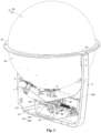
- a Luneberg lens antenna with a position-electrically adjustable feed of this embodiment includes: a reflecting plate 1, a feed 2, a Luneberg lens 3, and a position adjusting mechanism 4.
- the position adjusting mechanism 4 includes a mounting plate 41, a motor 42, a guide rail 43, a sliding block 44, a connecting base 45, a screw 46 and a moving base 47.
- a position of the mounting plate 41 is relatively fixed to a position of the Luneberg lens 3, a surface, facing the Luneberg lens 3, of the mounting plate 41 is a mounting surface 411.
- the Luneberg lens 3 is a spheroid Luneberg lens, and the mounting surface 411 is a plane.
- the guide rail 43 is mounted on the mounting plate 41 and between the mounting surface 411 and the Luneberg lens 3. Both ends of the screw 46 are rotationally mounted on the mounting plate 41, and orthographic projections, on the mounting surface 411, of an axis of the screw 46 and an axis of the guide rail 43 are parallel to each other.
- the motor 42 is fixed on the mounting plate 41 and configured for driving the screw 46 to rotate.
- the moving base 47 is provided with a screw hole, and the screw hole of the moving base 47 is in threaded connection with the screw 46.
- the reflecting plate 1 is arranged between the Luneberg lens 3 and the guide rail 43.
- the sliding block 44 is mounted on the reflecting plate 1 and in sliding fit connection with the guide rail 43.
- the connecting base 45 is connected with the moving base 47, and the other end thereof is connected with the reflecting plate 1.
- the feed 2 is mounted on a surface, facing the Luneberg lens 3, of the reflecting plate 1, and the surface, facing the Luneberg lens 3, of the reflecting plate 1 is a reflecting surface.
- the reflecting plate 1 of the Luneberg lens antenna with the position-electrically adjustable feed can slide along the guide rail 43 through the sliding block 44, so that a position of the feed 2 on the reflecting plate 1 can be adjusted relative to the Luneberg lens 3.
- the screw 46 is driven by the motor 42 to rotate to make the moving base 47 on the screw 46 move in a straight line along the axis of the screw 46, so that the connecting base 45 on the moving base 47 can drive the reflecting plate 1 to move along the guide rail 43.
- the reflecting plate 1 can move in a direction set by a shape of the guide rail 43, instead of being connected by a rotating shaft to adjust the position relative to the Luneberg lens 3, which is with good operational stability and convenient assembly. Therefore, the Luneberg lens antenna with the position-electrically adjustable feed has advantages of simple structure, reasonable design, good stability in adjusting a feed position, convenient assembly and low production cost.
- the position adjusting mechanism 4 further includes a guide rod 48, both ends of the guide rod 48 are mounted on the mounting plate 41, and an axis of the guide rod 48 is parallel to the axis of the screw 46; a guide part 471 is provided on the moving base 47, the guide part 471 is provided with a guide hole, and the guide hole of the moving base 47 is sleeved on the guide rod 48.
- the guide rail 43 includes a left guide rail 431 and a right guide rail 432, and both the left guide rail 431 and the right guide rail 432 are provided with a guide rail groove 433 along their axes.
- the motor 42, the screw 46 and the guide rod 48 are all between the left guide rail 431 and the right guide rail 432.
- the sliding block 44 includes a left sliding block 441 and a right sliding block 442. Both the left sliding block 441 and the right sliding block 442 are provided with a sliding part 443.
- the sliding part 443 of the left sliding block 441 is in sliding fit with the guide rail groove 433 of the left guide rail 431, and the sliding part 443 of the right sliding block 442 is in sliding fit with the guide rail groove 433 of the right guide rail 432.
- the guide rail grooves 433 on the left guide rail 431 and the right guide rail 432 are of a linear structure, and the sliding parts 443 on the left sliding block 441 and the right sliding block 442 are also of a linear structure; one end of the connecting base 45 is fixedly connected with the moving base 47, and the other end of the connecting base 45 is fixedly connected with the reflecting plate 1.
- cross sections of the guide rail grooves 433 on the left guide rail 431 and the right guide rail 432 are of an inverted-T-shaped structure, and cross sections of the sliding parts 443 on the left sliding block 441 and the right sliding block 442 are also of an inverted-T-shaped structure.
- the Luneberg lens antenna with the position-electrically adjustable feed further includes: a cover shell 5 and a support 6.
- the cover shell 5 includes an upper half shell 51 and a lower half shell 52.
- the upper half shell 51 is formed with an upper fixing ring 511 along an edge of its shell opening
- the lower half shell 52 is formed with a lower fixing ring 521 along an edge of its shell opening
- the upper half shell 51 is assembled with the lower half shell 52 to form a mounting chamber.
- the Luneberg lens 3 is mounted in the mounting chamber.
- both the upper fixing ring 511 of the upper half shell 51 and the lower fixing ring 521 of the lower half shell 52 are fixedly connected with the two fixing lugs 61 on the support 6.
- the mounting plate 41 is fixed on the support 6.
- the Luneberg lens antenna with the position-electrically adjustable feed further includes an outer shell 7.
- the outer shell 7 is fixed on the support 6.
- the position adjusting mechanism 4, the reflecting plate 1 and the feed 2 are all in the outer shell 7; and an edge of a shell opening of the outer shell 7 is affixed to an outer surface of the lower half shell 52.
- both the left guide rail 8 and the right guide rail 9 are of an arc-shaped strip structure, and a center of the left guide rail 8, a center of the right guide rail 9 and a spherical center of the Luneberg lens are collinear.
- the sliding parts 30 of the left sliding block 10 and the right sliding block 20 are also of an arc-shaped strip structure.
- One end of the connecting base 40 is fixedly connected with the moving base 50, and the other end of the connecting base 40 is formed with a pushing-type long hole 401, and a length direction of the pushing-type long hole 401 is vertical to the axis of the screw 60.
- the feed can move along the arc-shaped part left guide rail 8 and right guide rail 9 to adjust the position, so that no matter where the feed is adjusted, it can always point to the spherical center of the Luneberg lens, and thus, the feed receives and transmits signals better.
- the connecting base in Embodiment 2 is produced in one piece.
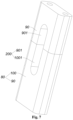
- the connecting base 80 of this embodiment is composed of an upper mounting base 90 and a lower mounting base 100.
- the lower mounting base 100 is fixed on the moving base, a down recessed part 1001 with a notch facing up is formed on the lower mounting base 100.
- the upper mounting base 90 is fixedly connected with the lower mounting base 100, an up recessed part 901 with a notch facing down is formed on the upper mounting base 90.
- the up recessed part 901 is assembled with the down recessed part 1001 to form the pushing-type long hole 200.
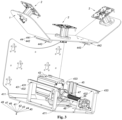
- a Luneberg lens antenna group is provided in this disclosure, which includes a first Luneberg lens antenna 300 and a number of second Luneberg lens antennas 400, and the first Luneberg lens antenna 300 and a number of second Luneberg lens antennas 400 are arranged side by side in a straight line.
- the first Luneberg lens antenna 300 is of a structure of the Luneberg lens antenna with the position-electrically adjustable feed described in Embodiment 1 after the outer shell is removed.
- Difference between each second Luneberg lens antenna 400 and the first Luneberg lens antenna 300 is that: there is no motor, screw and moving base on the second Luneberg lens antenna 400, and correspondingly, there are also no related components, such as a guide rod, connected with the motor, the screw and the moving base on the second Luneberg lens antenna 400 relative to the first Luneberg lens antenna 300.
- a connecting base 500 of the first Luneberg lens antenna 300 is fixed together with a connecting base 500 of each second Luneberg lens antenna 400 through a rigid component 600. It is noted here that, in implementation, the first Luneberg lens antenna 300 and each second Luneberg lens antenna 400 may share a mounting plate to mount the guide rail.
- the motor 3001 of the first Luneberg lens antenna 300 drives its screw 3002 to rotate to make a moving base 3003 of the first Luneberg lens antenna 300 move along the screw 3002, so that the connecting base 500 fixed together with the moving base 3003 on the first Luneberg lens antenna 300 and the connecting base 500 of the second Luneberg lens antenna 400 act simultaneously.
- the connecting bases 500 of the first Luneberg lens antenna 300 and the second Luneberg lens antennas 400 are all connected with the reflecting plate 700, the reflecting plates 700 of the first Luneberg lens antenna 300 and the second Luneberg lens antennas 400 are all provided with a feed 800, so that the positions of the feeds of a plurality of Luneberg lens antennas can be adjusted in a linkage mode, which is with high operation efficiency and convenient to use.
- a Luneberg lens antenna group is further provided in this disclosure, which includes a first Luneberg lens antenna 900 and a number of second Luneberg lens antennas 1000, and the first Luneberg lens antenna 900 and a number of second Luneberg lens antennas 1000 are arranged side by side in a straight line.
- the first Luneberg lens antenna 900 is of a structure of the Luneberg lens antenna with the position-electrically adjustable feed described in embodiment 2 after the shell is removed.
- Difference between each second Luneberg lens antenna 1000 and the first Luneberg lens antenna 900 is that: there is no motor and screw on the second Luneberg lens antenna 1000, and correspondingly, there are also no related components, such as a guide rod, connected with the motor and the screw on the second Luneberg lens antenna 1000 relative to the first Luneberg lens antenna 900.
- a screw 9002 of the first Luneberg lens antenna 900 is also in threaded connection with a screw hole of a moving base 2000 of each second Luneberg lens antenna 1000, and a guide hole in the moving base 2000 of the second Luneberg lens antenna 1000 is sleeved on a guide rod of the first Luneberg lens antenna 900.
- the first Luneberg lens antenna 900 and each second Luneberg lens antenna 1000 may share a mounting plate to mount the guide rail.
- the motor 1000 of the first Luneberg lens antenna 900 drives its screw 9002 to rotate to enable the moving base 2000 of the first Luneberg lens antenna 900 and the moving base 2000 of each second Luneberg lens antenna 1000 to move along the screw 9002.
- the moving bases 2000 of the first Luneberg lens antenna 900 and the second Luneberg lens antennas 1000 are all connected with the reflecting plate 4000 through a connection base 3000, reflecting plates 4000 of the first Luneberg lens antenna 900 and the second Luneberg lens antennas 1000 are all provided with a feed 5000, and then positions of the feeds of a plurality of Luneberg lens antennas can be adjusted in a linkage mode, which is with high operation efficiency, and is convenient to use.
Landscapes
- Physics & Mathematics (AREA)
- Electromagnetism (AREA)
- Aerials With Secondary Devices (AREA)
- Variable-Direction Aerials And Aerial Arrays (AREA)
Applications Claiming Priority (2)
| Application Number | Priority Date | Filing Date | Title |
|---|---|---|---|
| CN202120893757 | 2021-04-28 | ||
| PCT/CN2022/076807 WO2022227804A1 (zh) | 2021-04-28 | 2022-02-18 | 一种馈源位置可电调的龙伯透镜天线及龙伯透镜天线组 |
Publications (4)
| Publication Number | Publication Date |
|---|---|
| EP4333205A1 true EP4333205A1 (de) | 2024-03-06 |
| EP4333205A4 EP4333205A4 (de) | 2024-05-22 |
| EP4333205C0 EP4333205C0 (de) | 2025-05-21 |
| EP4333205B1 EP4333205B1 (de) | 2025-05-21 |
Family
ID=77098499
Family Applications (1)
| Application Number | Title | Priority Date | Filing Date |
|---|---|---|---|
| EP22794284.4A Active EP4333205B1 (de) | 2021-04-28 | 2022-02-18 | Lunburg-linsenantenne mit der fähigkeit zur elektrischen einstellung von positionen von einzügen und lunburg-linsenantennengruppe |
Country Status (8)
| Country | Link |
|---|---|
| US (1) | US11901628B1 (de) |
| EP (1) | EP4333205B1 (de) |
| JP (1) | JP7541786B2 (de) |
| KR (1) | KR102629401B1 (de) |
| CN (2) | CN113224529B (de) |
| BR (1) | BR112023017057A2 (de) |
| MX (1) | MX2023009791A (de) |
| WO (1) | WO2022227804A1 (de) |
Families Citing this family (8)
| Publication number | Priority date | Publication date | Assignee | Title |
|---|---|---|---|---|
| CN112290230B (zh) * | 2020-09-28 | 2022-02-25 | 广东福顺天际通信有限公司 | 一种辐射范围可调的龙伯透镜天线 |
| CN113224529B (zh) * | 2021-04-28 | 2025-02-14 | 佛山市粤海信通讯有限公司 | 一种馈源位置可电调的龙伯透镜天线及龙伯透镜天线组 |
| CN113782981A (zh) * | 2021-08-13 | 2021-12-10 | 西安电子科技大学 | 一种基于龙伯透镜的紧缩场分布式平面波生成器 |
| CN114597668B (zh) * | 2022-02-18 | 2025-08-26 | 广东盛路通信科技股份有限公司 | 一种龙伯球装置及电调龙伯透镜天线 |
| CN115149273B (zh) * | 2022-09-01 | 2022-11-18 | 佛山市粤海信通讯有限公司 | 一种有源透镜天线 |
| CN116632502B (zh) * | 2023-06-29 | 2024-05-28 | 上海尚远通讯科技有限公司 | 一种便携式5g北斗集成天线 |
| KR102847774B1 (ko) | 2023-09-04 | 2025-08-19 | 주식회사 엘지에너지솔루션 | 배터리 진단 장치, 배터리 팩, 전기 차량 및 배터리 진단 방법 |
| CN118659127B (zh) * | 2024-08-19 | 2024-12-17 | 佛山市粤海信通讯有限公司 | 一种铁路沿线信号覆盖用的透镜天线 |
Family Cites Families (20)
| Publication number | Priority date | Publication date | Assignee | Title |
|---|---|---|---|---|
| US3988736A (en) * | 1974-11-29 | 1976-10-26 | Communications Satellite Corporation (Comsat) | Steerable feed for toroidal antennas |
| FR2778042B1 (fr) * | 1998-04-23 | 2000-06-30 | Thomson Multimedia Sa | Systeme d'antennes de poursuite de satellites a defilement |
| JP3269458B2 (ja) * | 1998-07-06 | 2002-03-25 | 株式会社村田製作所 | アンテナ装置および送受信装置 |
| JP2002111359A (ja) | 2000-09-27 | 2002-04-12 | Murata Mfg Co Ltd | アンテナ装置、通信装置およびレーダ装置 |
| EP1589611B1 (de) * | 2003-01-30 | 2008-07-09 | Sumitomo Electric Industries, Ltd. | Linsenantennensystem |
| JP2004140860A (ja) * | 2003-12-12 | 2004-05-13 | Toshiba Corp | レンズアンテナ装置とその放射器位置決め制御方法 |
| JP2007006265A (ja) * | 2005-06-24 | 2007-01-11 | Sumitomo Electric Ind Ltd | 電波レンズアンテナ装置 |
| JP4816078B2 (ja) | 2005-12-28 | 2011-11-16 | 住友電気工業株式会社 | 電波レンズアンテナ装置 |
| DE102007056329A1 (de) * | 2007-11-22 | 2009-05-28 | Robert Bosch Gmbh | Winkelauflösender Radarsensor |
| JP2010034754A (ja) | 2008-07-28 | 2010-02-12 | National Institute Of Information & Communication Technology | レンズアンテナ装置 |
| US9054409B2 (en) * | 2011-07-21 | 2015-06-09 | Harris Corporation | Systems for positioning reflectors, such as passive reflectors |
| CN204205057U (zh) * | 2014-10-17 | 2015-03-11 | 成都国卫通信技术有限公司 | 一种直线导轨式换馈机构 |
| CN109643839B (zh) * | 2016-09-07 | 2021-02-19 | 康普技术有限责任公司 | 适合用于蜂窝和其它通信系统的多频带多波束透镜式天线 |
| CN106785444A (zh) | 2016-12-29 | 2017-05-31 | 中国电子科技集团公司第五十四研究所 | 一种双旋臂式龙伯透镜天线 |
| CN209248134U (zh) | 2019-01-02 | 2019-08-13 | 合肥若森智能科技有限公司 | 一种龙伯球透镜装配结构 |
| CN110380229B (zh) | 2019-06-06 | 2024-03-08 | 佛山市粤海信通讯有限公司 | 馈源可移动的龙伯透镜天线 |
| CN112151931B (zh) * | 2019-06-27 | 2025-11-04 | 合肥若森智能科技有限公司 | 一种龙伯透镜阵列及卫星天线 |
| US20210111499A1 (en) * | 2019-10-11 | 2021-04-15 | Amphenol Antenna Solutions, Inc. | Lens repeater with variable beamwidth |
| CN212011271U (zh) * | 2020-03-27 | 2020-11-24 | 佛山市粤海信通讯有限公司 | 一种龙伯透镜电调天线 |
| CN113224529B (zh) * | 2021-04-28 | 2025-02-14 | 佛山市粤海信通讯有限公司 | 一种馈源位置可电调的龙伯透镜天线及龙伯透镜天线组 |
-
2021
- 2021-05-26 CN CN202110569420.1A patent/CN113224529B/zh active Active
- 2021-05-26 CN CN202121143762.9U patent/CN215184547U/zh not_active Withdrawn - After Issue
-
2022
- 2022-02-18 KR KR1020237025470A patent/KR102629401B1/ko active Active
- 2022-02-18 MX MX2023009791A patent/MX2023009791A/es unknown
- 2022-02-18 BR BR112023017057A patent/BR112023017057A2/pt unknown
- 2022-02-18 WO PCT/CN2022/076807 patent/WO2022227804A1/zh not_active Ceased
- 2022-02-18 JP JP2023547338A patent/JP7541786B2/ja active Active
- 2022-02-18 EP EP22794284.4A patent/EP4333205B1/de active Active
- 2022-02-18 US US18/546,232 patent/US11901628B1/en active Active
Also Published As
| Publication number | Publication date |
|---|---|
| CN113224529A (zh) | 2021-08-06 |
| JP2024504855A (ja) | 2024-02-01 |
| US20240039168A1 (en) | 2024-02-01 |
| WO2022227804A1 (zh) | 2022-11-03 |
| US11901628B1 (en) | 2024-02-13 |
| CN113224529B (zh) | 2025-02-14 |
| EP4333205A4 (de) | 2024-05-22 |
| CN215184547U (zh) | 2021-12-14 |
| JP7541786B2 (ja) | 2024-08-29 |
| EP4333205C0 (de) | 2025-05-21 |
| EP4333205B1 (de) | 2025-05-21 |
| BR112023017057A2 (pt) | 2023-11-14 |
| MX2023009791A (es) | 2023-08-29 |
| KR20230117255A (ko) | 2023-08-07 |
| KR102629401B1 (ko) | 2024-01-25 |
Similar Documents
| Publication | Publication Date | Title |
|---|---|---|
| EP4333205A1 (de) | Lunburg-linsenantenne mit der fähigkeit zur elektrischen einstellung von positionen von einzügen und lunburg-linsenantennengruppe | |
| US10944169B2 (en) | Wireless telecommunication antenna mount and control system | |
| CN218006087U (zh) | 一种滴漆设备的定子角度调节结构 | |
| NL2036200B1 (en) | Angle adjusting mechanism of solar power generation panel for photovoltaic power generation | |
| CN117394042A (zh) | 一种天线反射板角度调节结构及天线 | |
| CN113342066B (zh) | 一种多模卫星天线云台控制装置 | |
| CN217926145U (zh) | 一种风电变桨装置 | |
| CN223014974U (zh) | 一种包膜组件及包膜机构 | |
| CN217003932U (zh) | 一种多功能全方位旋转连接机构 | |
| CN216867139U (zh) | 一种凸轮旋转压紧机构 | |
| CN220750036U (zh) | 一种角度调节组件及灯具 | |
| CN114447613A (zh) | 一种多频快速切换馈电网络 | |
| CN222662381U (zh) | 一种风电叶片飞边切割装置及其切割头安装机构 | |
| CN118992190B (zh) | 一种包膜装置及包膜设备 | |
| CN224036643U (zh) | 一种天线安装用调节转台 | |
| CN220101000U (zh) | 可调式门铰链结构 | |
| CN219395180U (zh) | 一种贴片机料带剥皮机构 | |
| CN222768831U (zh) | 一种风电叶片飞边切割装置及其监控安装机构 | |
| CN112664413B (zh) | 一种长久使用的叶片辅助结构件 | |
| CN223549747U (zh) | 一种便于拆卸链条的链条轨道 | |
| CN224213149U (zh) | 一种钢箱梁导向装置 | |
| CN222681521U (zh) | 风电叶片飞边切割装置 | |
| CN223954403U (zh) | 耐候性定日镜反射镜面装置 | |
| CN220435977U (zh) | 一种便于拆装的安防监控摄像头 | |
| CN120016923B (zh) | 抗风斜梁转动铰接点全自锁回转支撑驱动平单轴跟踪支架 |
Legal Events
| Date | Code | Title | Description |
|---|---|---|---|
| STAA | Information on the status of an ep patent application or granted ep patent |
Free format text: STATUS: THE INTERNATIONAL PUBLICATION HAS BEEN MADE |
|
| PUAI | Public reference made under article 153(3) epc to a published international application that has entered the european phase |
Free format text: ORIGINAL CODE: 0009012 |
|
| STAA | Information on the status of an ep patent application or granted ep patent |
Free format text: STATUS: REQUEST FOR EXAMINATION WAS MADE |
|
| 17P | Request for examination filed |
Effective date: 20230725 |
|
| AK | Designated contracting states |
Kind code of ref document: A1 Designated state(s): AL AT BE BG CH CY CZ DE DK EE ES FI FR GB GR HR HU IE IS IT LI LT LU LV MC MK MT NL NO PL PT RO RS SE SI SK SM TR |
|
| A4 | Supplementary search report drawn up and despatched |
Effective date: 20240424 |
|
| RIC1 | Information provided on ipc code assigned before grant |
Ipc: H01Q 19/06 20060101ALI20240417BHEP Ipc: H01Q 3/14 20060101AFI20240417BHEP |
|
| DAV | Request for validation of the european patent (deleted) | ||
| DAX | Request for extension of the european patent (deleted) | ||
| GRAP | Despatch of communication of intention to grant a patent |
Free format text: ORIGINAL CODE: EPIDOSNIGR1 |
|
| STAA | Information on the status of an ep patent application or granted ep patent |
Free format text: STATUS: GRANT OF PATENT IS INTENDED |
|
| RIC1 | Information provided on ipc code assigned before grant |
Ipc: H01Q 21/26 20060101ALI20241206BHEP Ipc: H01Q 15/14 20060101ALI20241206BHEP Ipc: H01Q 15/08 20060101ALI20241206BHEP Ipc: H01Q 1/12 20060101ALI20241206BHEP Ipc: H01Q 3/14 20060101AFI20241206BHEP |
|
| INTG | Intention to grant announced |
Effective date: 20250107 |
|
| GRAS | Grant fee paid |
Free format text: ORIGINAL CODE: EPIDOSNIGR3 |
|
| GRAA | (expected) grant |
Free format text: ORIGINAL CODE: 0009210 |
|
| STAA | Information on the status of an ep patent application or granted ep patent |
Free format text: STATUS: THE PATENT HAS BEEN GRANTED |
|
| AK | Designated contracting states |
Kind code of ref document: B1 Designated state(s): AL AT BE BG CH CY CZ DE DK EE ES FI FR GB GR HR HU IE IS IT LI LT LU LV MC MK MT NL NO PL PT RO RS SE SI SK SM TR |
|
| REG | Reference to a national code |
Ref country code: GB Ref legal event code: FG4D |
|
| REG | Reference to a national code |
Ref country code: CH Ref legal event code: EP |
|
| REG | Reference to a national code |
Ref country code: DE Ref legal event code: R096 Ref document number: 602022015036 Country of ref document: DE |
|
| REG | Reference to a national code |
Ref country code: IE Ref legal event code: FG4D |
|
| U01 | Request for unitary effect filed |
Effective date: 20250603 |
|
| U07 | Unitary effect registered |
Designated state(s): AT BE BG DE DK EE FI FR IT LT LU LV MT NL PT RO SE SI Effective date: 20250611 |
|
| PG25 | Lapsed in a contracting state [announced via postgrant information from national office to epo] |
Ref country code: ES Free format text: LAPSE BECAUSE OF FAILURE TO SUBMIT A TRANSLATION OF THE DESCRIPTION OR TO PAY THE FEE WITHIN THE PRESCRIBED TIME-LIMIT Effective date: 20250521 |
|
| PG25 | Lapsed in a contracting state [announced via postgrant information from national office to epo] |
Ref country code: NO Free format text: LAPSE BECAUSE OF FAILURE TO SUBMIT A TRANSLATION OF THE DESCRIPTION OR TO PAY THE FEE WITHIN THE PRESCRIBED TIME-LIMIT Effective date: 20250821 Ref country code: GR Free format text: LAPSE BECAUSE OF FAILURE TO SUBMIT A TRANSLATION OF THE DESCRIPTION OR TO PAY THE FEE WITHIN THE PRESCRIBED TIME-LIMIT Effective date: 20250822 |
|
| PG25 | Lapsed in a contracting state [announced via postgrant information from national office to epo] |
Ref country code: PL Free format text: LAPSE BECAUSE OF FAILURE TO SUBMIT A TRANSLATION OF THE DESCRIPTION OR TO PAY THE FEE WITHIN THE PRESCRIBED TIME-LIMIT Effective date: 20250521 |
|
| PG25 | Lapsed in a contracting state [announced via postgrant information from national office to epo] |
Ref country code: HR Free format text: LAPSE BECAUSE OF FAILURE TO SUBMIT A TRANSLATION OF THE DESCRIPTION OR TO PAY THE FEE WITHIN THE PRESCRIBED TIME-LIMIT Effective date: 20250521 |
|
| PG25 | Lapsed in a contracting state [announced via postgrant information from national office to epo] |
Ref country code: RS Free format text: LAPSE BECAUSE OF FAILURE TO SUBMIT A TRANSLATION OF THE DESCRIPTION OR TO PAY THE FEE WITHIN THE PRESCRIBED TIME-LIMIT Effective date: 20250821 |
|
| PG25 | Lapsed in a contracting state [announced via postgrant information from national office to epo] |
Ref country code: IS Free format text: LAPSE BECAUSE OF FAILURE TO SUBMIT A TRANSLATION OF THE DESCRIPTION OR TO PAY THE FEE WITHIN THE PRESCRIBED TIME-LIMIT Effective date: 20250921 |
|
| PG25 | Lapsed in a contracting state [announced via postgrant information from national office to epo] |
Ref country code: SM Free format text: LAPSE BECAUSE OF FAILURE TO SUBMIT A TRANSLATION OF THE DESCRIPTION OR TO PAY THE FEE WITHIN THE PRESCRIBED TIME-LIMIT Effective date: 20250521 |
|
| PG25 | Lapsed in a contracting state [announced via postgrant information from national office to epo] |
Ref country code: CZ Free format text: LAPSE BECAUSE OF FAILURE TO SUBMIT A TRANSLATION OF THE DESCRIPTION OR TO PAY THE FEE WITHIN THE PRESCRIBED TIME-LIMIT Effective date: 20250521 |
|
| PG25 | Lapsed in a contracting state [announced via postgrant information from national office to epo] |
Ref country code: SK Free format text: LAPSE BECAUSE OF FAILURE TO SUBMIT A TRANSLATION OF THE DESCRIPTION OR TO PAY THE FEE WITHIN THE PRESCRIBED TIME-LIMIT Effective date: 20250521 |
|
| PLBE | No opposition filed within time limit |
Free format text: ORIGINAL CODE: 0009261 |
|
| STAA | Information on the status of an ep patent application or granted ep patent |
Free format text: STATUS: NO OPPOSITION FILED WITHIN TIME LIMIT |
|
| U20 | Renewal fee for the european patent with unitary effect paid |
Year of fee payment: 5 Effective date: 20260226 |
|
| REG | Reference to a national code |
Ref country code: CH Ref legal event code: L10 Free format text: ST27 STATUS EVENT CODE: U-0-0-L10-L00 (AS PROVIDED BY THE NATIONAL OFFICE) Effective date: 20260402 |
|
| 26N | No opposition filed |
Effective date: 20260224 |