EP4333220A1 - Ladestecker und ladevorrichtung - Google Patents
Ladestecker und ladevorrichtung Download PDFInfo
- Publication number
- EP4333220A1 EP4333220A1 EP22794852.8A EP22794852A EP4333220A1 EP 4333220 A1 EP4333220 A1 EP 4333220A1 EP 22794852 A EP22794852 A EP 22794852A EP 4333220 A1 EP4333220 A1 EP 4333220A1
- Authority
- EP
- European Patent Office
- Prior art keywords
- power plug
- control box
- groove
- charging connector
- charging
- Prior art date
- Legal status (The legal status is an assumption and is not a legal conclusion. Google has not performed a legal analysis and makes no representation as to the accuracy of the status listed.)
- Pending
Links
Images



Classifications
-
- H—ELECTRICITY
- H01—ELECTRIC ELEMENTS
- H01R—ELECTRICALLY-CONDUCTIVE CONNECTIONS; STRUCTURAL ASSOCIATIONS OF A PLURALITY OF MUTUALLY-INSULATED ELECTRICAL CONNECTING ELEMENTS; COUPLING DEVICES; CURRENT COLLECTORS
- H01R31/00—Coupling parts supported only by co-operation with counterpart
- H01R31/06—Intermediate parts for linking two coupling parts, e.g. adapter
-
- B—PERFORMING OPERATIONS; TRANSPORTING
- B60—VEHICLES IN GENERAL
- B60L—PROPULSION OF ELECTRICALLY-PROPELLED VEHICLES; SUPPLYING ELECTRIC POWER FOR AUXILIARY EQUIPMENT OF ELECTRICALLY-PROPELLED VEHICLES; ELECTRODYNAMIC BRAKE SYSTEMS FOR VEHICLES IN GENERAL; MAGNETIC SUSPENSION OR LEVITATION FOR VEHICLES; MONITORING OPERATING VARIABLES OF ELECTRICALLY-PROPELLED VEHICLES; ELECTRIC SAFETY DEVICES FOR ELECTRICALLY-PROPELLED VEHICLES
- B60L53/00—Methods of charging batteries, specially adapted for electric vehicles; Charging stations or on-board charging equipment therefor; Exchange of energy storage elements in electric vehicles
- B60L53/10—Methods of charging batteries, specially adapted for electric vehicles; Charging stations or on-board charging equipment therefor; Exchange of energy storage elements in electric vehicles characterised by the energy transfer between the charging station and the vehicle
- B60L53/14—Conductive energy transfer
- B60L53/16—Connectors, e.g. plugs or sockets, specially adapted for charging electric vehicles
-
- B—PERFORMING OPERATIONS; TRANSPORTING
- B60—VEHICLES IN GENERAL
- B60L—PROPULSION OF ELECTRICALLY-PROPELLED VEHICLES; SUPPLYING ELECTRIC POWER FOR AUXILIARY EQUIPMENT OF ELECTRICALLY-PROPELLED VEHICLES; ELECTRODYNAMIC BRAKE SYSTEMS FOR VEHICLES IN GENERAL; MAGNETIC SUSPENSION OR LEVITATION FOR VEHICLES; MONITORING OPERATING VARIABLES OF ELECTRICALLY-PROPELLED VEHICLES; ELECTRIC SAFETY DEVICES FOR ELECTRICALLY-PROPELLED VEHICLES
- B60L53/00—Methods of charging batteries, specially adapted for electric vehicles; Charging stations or on-board charging equipment therefor; Exchange of energy storage elements in electric vehicles
- B60L53/10—Methods of charging batteries, specially adapted for electric vehicles; Charging stations or on-board charging equipment therefor; Exchange of energy storage elements in electric vehicles characterised by the energy transfer between the charging station and the vehicle
- B60L53/14—Conductive energy transfer
- B60L53/18—Cables specially adapted for charging electric vehicles
-
- H—ELECTRICITY
- H01—ELECTRIC ELEMENTS
- H01R—ELECTRICALLY-CONDUCTIVE CONNECTIONS; STRUCTURAL ASSOCIATIONS OF A PLURALITY OF MUTUALLY-INSULATED ELECTRICAL CONNECTING ELEMENTS; COUPLING DEVICES; CURRENT COLLECTORS
- H01R13/00—Details of coupling devices of the kinds covered by groups H01R12/70 or H01R24/00 - H01R33/00
- H01R13/02—Contact members
- H01R13/04—Pins or blades for co-operation with sockets
-
- H—ELECTRICITY
- H01—ELECTRIC ELEMENTS
- H01R—ELECTRICALLY-CONDUCTIVE CONNECTIONS; STRUCTURAL ASSOCIATIONS OF A PLURALITY OF MUTUALLY-INSULATED ELECTRICAL CONNECTING ELEMENTS; COUPLING DEVICES; CURRENT COLLECTORS
- H01R13/00—Details of coupling devices of the kinds covered by groups H01R12/70 or H01R24/00 - H01R33/00
- H01R13/02—Contact members
- H01R13/10—Sockets for co-operation with pins or blades
- H01R13/11—Resilient sockets
- H01R13/111—Resilient sockets co-operating with pins having a circular transverse section
-
- H—ELECTRICITY
- H01—ELECTRIC ELEMENTS
- H01R—ELECTRICALLY-CONDUCTIVE CONNECTIONS; STRUCTURAL ASSOCIATIONS OF A PLURALITY OF MUTUALLY-INSULATED ELECTRICAL CONNECTING ELEMENTS; COUPLING DEVICES; CURRENT COLLECTORS
- H01R13/00—Details of coupling devices of the kinds covered by groups H01R12/70 or H01R24/00 - H01R33/00
- H01R13/02—Contact members
- H01R13/22—Contacts for co-operating by abutting
- H01R13/24—Contacts for co-operating by abutting resilient; resiliently-mounted
- H01R13/2442—Contacts for co-operating by abutting resilient; resiliently-mounted with a single cantilevered beam
-
- H—ELECTRICITY
- H01—ELECTRIC ELEMENTS
- H01R—ELECTRICALLY-CONDUCTIVE CONNECTIONS; STRUCTURAL ASSOCIATIONS OF A PLURALITY OF MUTUALLY-INSULATED ELECTRICAL CONNECTING ELEMENTS; COUPLING DEVICES; CURRENT COLLECTORS
- H01R13/00—Details of coupling devices of the kinds covered by groups H01R12/70 or H01R24/00 - H01R33/00
- H01R13/40—Securing contact members in or to a base or case; Insulating of contact members
-
- H—ELECTRICITY
- H01—ELECTRIC ELEMENTS
- H01R—ELECTRICALLY-CONDUCTIVE CONNECTIONS; STRUCTURAL ASSOCIATIONS OF A PLURALITY OF MUTUALLY-INSULATED ELECTRICAL CONNECTING ELEMENTS; COUPLING DEVICES; CURRENT COLLECTORS
- H01R13/00—Details of coupling devices of the kinds covered by groups H01R12/70 or H01R24/00 - H01R33/00
- H01R13/40—Securing contact members in or to a base or case; Insulating of contact members
- H01R13/42—Securing in a demountable manner
- H01R13/428—Securing in a demountable manner by resilient locking means on the contact members; by locking means on resilient contact members
-
- H—ELECTRICITY
- H01—ELECTRIC ELEMENTS
- H01R—ELECTRICALLY-CONDUCTIVE CONNECTIONS; STRUCTURAL ASSOCIATIONS OF A PLURALITY OF MUTUALLY-INSULATED ELECTRICAL CONNECTING ELEMENTS; COUPLING DEVICES; CURRENT COLLECTORS
- H01R13/00—Details of coupling devices of the kinds covered by groups H01R12/70 or H01R24/00 - H01R33/00
- H01R13/46—Bases; Cases
-
- H—ELECTRICITY
- H01—ELECTRIC ELEMENTS
- H01R—ELECTRICALLY-CONDUCTIVE CONNECTIONS; STRUCTURAL ASSOCIATIONS OF A PLURALITY OF MUTUALLY-INSULATED ELECTRICAL CONNECTING ELEMENTS; COUPLING DEVICES; CURRENT COLLECTORS
- H01R13/00—Details of coupling devices of the kinds covered by groups H01R12/70 or H01R24/00 - H01R33/00
- H01R13/62—Means for facilitating engagement or disengagement of coupling parts or for holding them in engagement
- H01R13/629—Additional means for facilitating engagement or disengagement of coupling parts, e.g. aligning or guiding means, levers, gas pressure electrical locking indicators, manufacturing tolerances
-
- H—ELECTRICITY
- H01—ELECTRIC ELEMENTS
- H01R—ELECTRICALLY-CONDUCTIVE CONNECTIONS; STRUCTURAL ASSOCIATIONS OF A PLURALITY OF MUTUALLY-INSULATED ELECTRICAL CONNECTING ELEMENTS; COUPLING DEVICES; CURRENT COLLECTORS
- H01R13/00—Details of coupling devices of the kinds covered by groups H01R12/70 or H01R24/00 - H01R33/00
- H01R13/62—Means for facilitating engagement or disengagement of coupling parts or for holding them in engagement
- H01R13/639—Additional means for holding or locking coupling parts together, after engagement, e.g. separate keylock, retainer strap
-
- H—ELECTRICITY
- H01—ELECTRIC ELEMENTS
- H01R—ELECTRICALLY-CONDUCTIVE CONNECTIONS; STRUCTURAL ASSOCIATIONS OF A PLURALITY OF MUTUALLY-INSULATED ELECTRICAL CONNECTING ELEMENTS; COUPLING DEVICES; CURRENT COLLECTORS
- H01R13/00—Details of coupling devices of the kinds covered by groups H01R12/70 or H01R24/00 - H01R33/00
- H01R13/73—Means for mounting coupling parts to apparatus or structures, e.g. to a wall
-
- H—ELECTRICITY
- H01—ELECTRIC ELEMENTS
- H01R—ELECTRICALLY-CONDUCTIVE CONNECTIONS; STRUCTURAL ASSOCIATIONS OF A PLURALITY OF MUTUALLY-INSULATED ELECTRICAL CONNECTING ELEMENTS; COUPLING DEVICES; CURRENT COLLECTORS
- H01R24/00—Two-part coupling devices, or either of their cooperating parts, characterised by their overall structure
- H01R24/28—Coupling parts carrying pins, blades or analogous contacts and secured only to wire or cable
-
- H—ELECTRICITY
- H01—ELECTRIC ELEMENTS
- H01R—ELECTRICALLY-CONDUCTIVE CONNECTIONS; STRUCTURAL ASSOCIATIONS OF A PLURALITY OF MUTUALLY-INSULATED ELECTRICAL CONNECTING ELEMENTS; COUPLING DEVICES; CURRENT COLLECTORS
- H01R13/00—Details of coupling devices of the kinds covered by groups H01R12/70 or H01R24/00 - H01R33/00
- H01R13/46—Bases; Cases
- H01R13/502—Bases; Cases composed of different pieces
- H01R13/512—Bases; Cases composed of different pieces assembled by screw or screws
-
- H—ELECTRICITY
- H01—ELECTRIC ELEMENTS
- H01R—ELECTRICALLY-CONDUCTIVE CONNECTIONS; STRUCTURAL ASSOCIATIONS OF A PLURALITY OF MUTUALLY-INSULATED ELECTRICAL CONNECTING ELEMENTS; COUPLING DEVICES; CURRENT COLLECTORS
- H01R2105/00—Three poles
-
- H—ELECTRICITY
- H01—ELECTRIC ELEMENTS
- H01R—ELECTRICALLY-CONDUCTIVE CONNECTIONS; STRUCTURAL ASSOCIATIONS OF A PLURALITY OF MUTUALLY-INSULATED ELECTRICAL CONNECTING ELEMENTS; COUPLING DEVICES; CURRENT COLLECTORS
- H01R2201/00—Connectors or connections adapted for particular applications
- H01R2201/26—Connectors or connections adapted for particular applications for vehicles
-
- Y—GENERAL TAGGING OF NEW TECHNOLOGICAL DEVELOPMENTS; GENERAL TAGGING OF CROSS-SECTIONAL TECHNOLOGIES SPANNING OVER SEVERAL SECTIONS OF THE IPC; TECHNICAL SUBJECTS COVERED BY FORMER USPC CROSS-REFERENCE ART COLLECTIONS [XRACs] AND DIGESTS
- Y02—TECHNOLOGIES OR APPLICATIONS FOR MITIGATION OR ADAPTATION AGAINST CLIMATE CHANGE
- Y02T—CLIMATE CHANGE MITIGATION TECHNOLOGIES RELATED TO TRANSPORTATION
- Y02T10/00—Road transport of goods or passengers
- Y02T10/60—Other road transportation technologies with climate change mitigation effect
- Y02T10/70—Energy storage systems for electromobility, e.g. batteries
-
- Y—GENERAL TAGGING OF NEW TECHNOLOGICAL DEVELOPMENTS; GENERAL TAGGING OF CROSS-SECTIONAL TECHNOLOGIES SPANNING OVER SEVERAL SECTIONS OF THE IPC; TECHNICAL SUBJECTS COVERED BY FORMER USPC CROSS-REFERENCE ART COLLECTIONS [XRACs] AND DIGESTS
- Y02—TECHNOLOGIES OR APPLICATIONS FOR MITIGATION OR ADAPTATION AGAINST CLIMATE CHANGE
- Y02T—CLIMATE CHANGE MITIGATION TECHNOLOGIES RELATED TO TRANSPORTATION
- Y02T10/00—Road transport of goods or passengers
- Y02T10/60—Other road transportation technologies with climate change mitigation effect
- Y02T10/7072—Electromobility specific charging systems or methods for batteries, ultracapacitors, supercapacitors or double-layer capacitors
-
- Y—GENERAL TAGGING OF NEW TECHNOLOGICAL DEVELOPMENTS; GENERAL TAGGING OF CROSS-SECTIONAL TECHNOLOGIES SPANNING OVER SEVERAL SECTIONS OF THE IPC; TECHNICAL SUBJECTS COVERED BY FORMER USPC CROSS-REFERENCE ART COLLECTIONS [XRACs] AND DIGESTS
- Y02—TECHNOLOGIES OR APPLICATIONS FOR MITIGATION OR ADAPTATION AGAINST CLIMATE CHANGE
- Y02T—CLIMATE CHANGE MITIGATION TECHNOLOGIES RELATED TO TRANSPORTATION
- Y02T90/00—Enabling technologies or technologies with a potential or indirect contribution to GHG emissions mitigation
- Y02T90/10—Technologies relating to charging of electric vehicles
- Y02T90/14—Plug-in electric vehicles
Definitions
- the present disclosure relates to the technical field of electric vehicles, and particularly to a charging connector and a charging device.
- the charging device of an electric vehicle usually includes a charging gun, a control box and a power plug.
- the control box and the charging gun are connected to each other through a cable.
- the control box and the power plug are connected to each other through a cable.
- the charging device is connected to the electric vehicle through the charging gun and connected to a power socket through the power plug.
- An objective of the present disclosure is to provide a charging connector and a charging device, so as to solve the technical problem of poor adaptability of the charging device.
- the present disclosure provides a charging connector, including a control box and a power plug.
- the control box is electrically connected to a charging gun, and the control box is provided with a three-phase terminal.
- the power plug is provided with a connecting structure, and connecting structure detachably connects the power plug with the control box and electrically connects the power plug with the three-phase terminal.
- the present disclosure provides a charging device, including a charging gun and the aforementioned charging connector.
- the charging gun is electrically connected to the control box.
- the charging gun is electrically connected to the control box in the charging connector according to the present disclosure, and the charging connector is connected to the electric vehicle through the charging gun.
- the power plug is detachably connected to the control box, so that the power plug can be conveniently replaced to adapt to a power socket, and the charging connector can be used movably, thereby improving the adaptability and convenience of the charging connector.
- the power plug and the control box are connected directly to each other, eliminating the cable between the power plug and the control box, which contributes to making the structure of the charging connector more compact and reducing the occupied space of the charging connector.
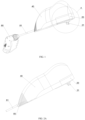
- the present disclosure provides a charging connector, as illustrated in FIGS. 1 to 2B and 3B , including a control box 40 and a power plug 20.
- the control box 40 is electrically connected to a charging gun 80.
- the control box 40 is provided with a three-phase terminal 41.
- the power plug 20 is provided with a connecting structure which detachably connects the power plug 20 with the control box 40 and electrically connects the power plug 20 with the three-phase terminal 41.
- the charging gun 80 is electrically connected to the control box 40 in the charging connector according to the present disclosure, and the charging connector is connected to the electric vehicle through the charging gun 80.
- the power plug 20 is detachably connected to the control box 40, so that the power plug 20 can be conveniently replaced to adapt to a power socket, and the charging connector can be used movably, thereby improving the adaptability and convenience of the charging connector.
- the power plug 20 and the control box 40 are connected directly to each other, eliminating a cable 81 between the power plug 20 and the control box 40, which contributes to making the structure of the charging connector more compact and reducing the occupied space of the charging connector.
- control box 40 is connected to the power plug 20 and the charging gun 80 through a cable 81, respectively.
- the control box 40 should be placed on a platform rather than being suspended. Therefore, the control box 40 generally should not be placed randomly, resulting in the charging gun 80 being able to extend over a range much smaller than a total length of the cable 81 between the control box 40 and the power plug 20 and the cable 81 between the control box 40 and the charging gun 80, i.e., the charging gun 80 being able to extend over a range much smaller than the total length of the cable 81 used by the charging device.
- the power plug 20 and the control box 40 are connected directly to each other.
- the charging gun 80 is able to extend over a range substantially equal to a length of the cable 81 between the charging gun 80 and the control box 40, i.e., the charging gun 80 is able to extend over a range substantially equal to a total length of the cable 81 used by the charging device, which is beneficial to making full use of the cable 81, saving the cable 81, reducing the space occupied by the cable 81 and extending the charging range.
- the connecting structure is not limited to one type.
- the connecting structure includes a bolt connected to the power plug 20, the control box 40 is provided with a bolt hole, and the power plug 20 is mounted on the control box 40 by screwing the bolt to the bolt hole, so as to realize mounting the power plug 20 to the control box 40 and detaching the power plug 20 from the control box 40 by removing the bolt.
- the inventor further improves the connecting structure.
- the connecting structure includes a sliding groove 30 disposed on the power plug 20, and the control box 40 is provided with a slider 50.
- the slider 50 is slidably embedded in the sliding groove 30 and is restricted from being separated from the sliding groove 30.
- the slider 50 and the sliding groove 30 have a function of guidance, and the power plug 20 is pushed along the sliding groove 30 during mounting so as to facilitate the mounting.
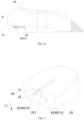
- the sliding groove 30 includes a first groove portion 31 and a second groove portion 32 being in communication with the first groove portion 31.
- the first groove portion 31 and the second groove portion 32 are sequentially distributed in a groove depth direction 11 of the sliding groove 30.
- the slider 50 penetrates the first groove portion 31, and an end of the slider 50 is disposed in the second groove portion 32.
- a top wall 321 of the second groove portion restricts a movement of the slider 50 in a direction opposite to the groove depth direction 11. As illustrated in FIGS.
- a width of the second groove portion 32 is greater than that of the first groove portion 31, the top wall 321 of the second groove portion is close to the first groove portion 31, and the end of the slider 50 can abut against the top wall 321 of the second groove portion, so that the top wall 321 of the second groove portion blocks the movement of the slider 50 in the direction opposite to the groove depth direction 11, and a bottom wall of the second groove portion 32 blocks the movement of the slider 50 in the groove depth direction 11, thereby restricting the slider 50 from being separated from the sliding groove 30 in the groove depth direction 11 or in a direction opposite thereto.
- the slider 50 includes a connecting post 51 and a sliding portion 52 connected to an end of the connecting post 51.
- the connecting post 51 penetrates the first groove portion 31, the sliding portion 52 is disposed in the second groove portion 32, and a side wall of the sliding portion 52 is in contact with a side wall of the second groove portion 32 to guide the sliding portion 52 and the slider 50 to move in the sliding groove 30.
- the sliding portion 52 is a revolving body, and an axis of the sliding portion 52 is disposed along the groove depth direction 11, so as to reduce a contact surface between the side wall of the sliding portion 52 and the side wall of the second groove portion 32, which is beneficial for the power plug 20 to move more smoothly.
- a diameter of the sliding portion 52 is greater than a width of the first groove portion 31, and a top surface of the sliding portion 52 can abut against the top wall 321 of the second groove portion.
- the connecting post 51 is a cylinder, and an axis of the connecting post 51 coincides with the axis of the sliding portion 52, both of which are parallel to the groove depth direction 11.
- the power plug 20 and the control box 40 need to be fixed together by a mechanical connection, and on the other hand, the three-phase terminal 41 of the control box 40 needs to be electrically connected to three pins 21 of the power plug 20.
- the conventional connection mode between the pin 21 and the socket may be adopted.
- the inventor makes a further improvement.
- FIG. 3C is a schematic diagram of the sliding groove 30 and the metal contact reed 22 of the power plug 20 that are connected to the control box 40, and the body of the power plug 20 is omitted in FIG. 3C .
- the slider 50 is connected to the metal contact reed 22 by contact.
- the slider 50 slides into the sliding groove 30 and contacts the metal contact reed 22, so that one electrical terminal 10 of the power plug 20 (i.e., one pin 21 of the power plug 20) is electrically connected to one electrical terminal 10 of the three-phase terminal 41.
- the end of the slider 50 is constructed as a metal contact.
- the metal contact reed 22 is provided on the bottom wall of the second groove portion 32, and the metal contact reed 22 is constructed to apply an elastic force to the slider 50 in a direction opposite to the groove depth direction 11.
- the sliding portion 52 moves to a position corresponding to the metal contact reed 22 along the second groove portion 32. In this position, a bottom wall of the sliding portion 52 applies a pressure on the metal contact reed 22 in the groove depth direction 11, and the metal contact reed 22 is in close contact with the sliding portion 52 by its own elastic force, thereby ensuring the reliability of connection.
- the slider 50 connects the control box 40 with the power plug 20 on the one hand, and achieves an electrical connection on the other hand, which simplifies the structure, ensures the reliability and stability of connection, facilitates the assembly and disassembly, and improves the convenience of use.
- the control box 40 is provided with a first accommodating groove 74 for accommodating the power plug 20.
- the power plug 20 is mounted in the first accommodating groove 74, as illustrated in FIG. 2A , so as to facilitate mounting the power plug 20 and the control box 40 on an external power socket.
- the slider 50 is disposed on a bottom wall 741 of the first accommodating groove.
- at least one electrical terminal 10 of the three-phase terminal 41 is disposed on a side wall 742 of the first accommodating groove.
- the power plug 20 is constructed to be capable of being moved along the sliding groove 30 to abut against the side wall 742 of the first accommodating groove, and the power plug 20 is electrically connected to the electrical terminal 10 disposed on the side wall 742 of the first accommodating groove.
- the power plug 20 is moved on the control box 40 along the sliding groove 30, so that under the guidance of the sliding groove 30, the power plug 20 can be moved toward the side wall 742 of the first accommodating groove more stably and smoothly, which is beneficial to ensuring the smooth engagement between the power plug 20 and the electrical terminal 10 on the side wall 742 of the first accommodating groove, thereby ensuring the stability of the electrical connection.
- the charging connector includes a docking mechanism 60, which includes a conductive post 61 and a conductive barrel 62. As illustrated in FIGS. 8 and 9 , the conductive post 61 is inserted into the conductive barrel 62 to be electrically connected to the conductive barrel 62. The conductive post 61 and the conductive barrel 62 are disposed in a sliding direction of the sliding groove 30. During mounting, the power plug 20 is moved along the sliding groove 30, so that the conductive post 61 is inserted into the conductive barrel 62, which is convenient to operate and makes the connection reliable.
- the conductive post 61 is constructed to be the electrical terminal 10 disposed on the side wall 742 of the first accommodating groove, and the conductive barrel 62 is disposed on the power plug 20.
- the conductive barrel 62 is constructed to be the electrical terminal 10 disposed on the side wall 742 of the first accommodating groove, and the conductive post 61 is disposed on the power plug 20.
- a longitudinal direction of the pin 21 of the power plug 20 may be disposed along the groove depth direction 11, i.e., the longitudinal direction of the pin 21 is perpendicular to the sliding direction of the sliding groove 30.
- the longitudinal direction of the pin 21 of the power plug 20 may be disposed along the sliding direction of the sliding groove 30, and when being mounted on the power socket, the control box 40 and the power plug 20 are distributed up and down, so that the power plug 20 can carry the control box 40 conveniently.
- an end of the conductive barrel 62 is provided with a crimping arm 63 for pressing the conductive post 61 inward.
- the guide post is inserted into the conductive barrel 62 to drive the crimping arm 63 to expand outward, and the crimping arm 63 is deformed to press the conductive post 61 inward by its elastic force, so that the connection between the power plug 20 and the control box 40 is more secure, which on the one hand facilitates the docking of the conductive post 61 and the conductive barrel 62, and on the other hand improves the reliability of connection.
- the three-phase terminal 41 includes an L terminal, an N terminal and a PE terminal
- the power plug 20 includes the pins 21 of L-phase, N-phase and PE-phase corresponding to the L terminal, the N terminal and the PE terminal.
- the slider 50 and the metal contact reed 22 are of PE-phase, and there are two docking mechanisms 60 being of L-phase and N-phase, respectively.
- the control box 40 includes a housing 70 and a circuit board 42 mounted therein, and the three-phase terminal 41 is electrically connected to the circuit board 42.
- the three-phase terminal 41 serves as an input terminal of the control box 40, and the current is transmitted to the circuit board 42 through the three-phase terminal 41.
- the housing 70 protects the circuit board 42.
- the housing 70 includes an upper housing 71 and a lower cover 72.
- the upper housing 71 is provided with a cavity for accommodating the circuit board 42, and the upper housing 71 and the lower cover 72 may be fixedly connected to each other by a first screw 73. Further, as illustrated in FIGS.
- an outer edge of the upper housing 71 is provided with a recess 711 for accommodating a sealing ring 712 which cooperates with the lower cover 72 to improve the sealability between the upper housing 71 and the lower cover 72 and improve the waterproof and dustproof performance.
- the control box 40 includes a rubber cushion 75 mounted in the housing 70, and the rubber cushion 75 is provided with a second accommodating groove 751 for accommodating the circuit board 42. As illustrated in FIGS. 10 and 13 , the rubber cushion 75 is fixed in the cavity of the upper housing 71 through a second screw 76, and the circuit board 42 is disposed in the second accommodating cavity, thereby contributing to improving the shock resistance and reliability of the charging connector.
- the cavity of the upper housing 71 is filled with glue for fixing the rubber cushion 75 and the circuit board 42, which is beneficial to improving the sealability and the reliability of connection.
- the circuit board 42 and the rubber cushion 75 are mounted and fixed in the upper housing 71 through the second screw 76, then the sealing ring 712 is mounted in the recess 711 of the upper housing 71, then the glue is injected into the cavity of the upper housing 71, then the lower cover 72 is mounted on the upper housing 71 after the glue is solidified and cooled, then the first screw 73 is mounted, and finally the power plug 20 is mounted in the housing 70, thereby completing the assembly of the charging connector.
- the control box 40 and the power plug 20 are abutted against each other through the connecting structure, to form a detachable integrated structure without a cable to connect the control box 40 and the power plug 20.
- the charging connector may be provided independently, the control box 40 provides an interface for being connected to the charging gun 80, one end of the cable 81 is connected to the charging gun 80, and the other end of the cable 81 is detachably connected to the interface.
- the charging connector may be provided in conjunction with the charging gun 80, the control box 40 and the charging gun 80 are connected through the cable 81, and the cable 81 and the control box 40 are fixedly connected.
- the control box 40 is provided with an outlet rubber plug 83 through which the cable 81 passes, thereby improving the sealability.
- the present disclosure provides a charging device, as illustrated in FIGS. 1 and 15 , including a charging gun 80 and the aforementioned charging connector, and the charging gun 80 is electrically connected to the control box 40.
- the charging gun 80 is connected to the control box 40 through a cable 81, and the cable 81 is electrically connected to the circuit board 42 in the control box 40.
- the current transferred to the control box 40 is output to the charging gun 80 through the circuit board 42, and the circuit board 42 can control the current output of the control box 40 to guarantee stable charging of the electric vehicle.
- the power plug 20 is connected to the control box 40 through a connecting structure, the power plug 20 is mounted on a power socket, and the charging gun 80 is connected to the electric vehicle to charge the electric vehicle.
- the circuit board 42 and the rubber cushion 75 are mounted and fixed in the upper housing 71 through a second screw 76, and the charging gun 80 and the control box 40 are connected through the cable 81; then a sealing ring 712 is mounted in the groove 711 of the upper housing 71; then glue is injected into the cavity of the upper housing 71; thereafter the lower cover 72 is mounted on the upper housing 71 after the glue is solidified and cooled; then the first screw 73 is mounted, and finally the power plug 20 is mounted in the housing 70, thereby completing the assembly of the charging connector.
- the charging gun 80 is electrically connected to the control box 40 of the charging connector according to the present disclosure, and the charging connector is connected to the electric vehicle through the charging gun 80.
- the power plug 20 is detachably connected to the control box 40, so that the power plug 20 can be conveniently replaced to adapt to the power socket, thereby improving the adaptability and convenience of the charging connector.
- the power plug 20 and the control box 40 are connected directly to each other, eliminating a cable 81 between the power plug 20 and the control box 40, which contributes to making the structure of the charging connector more compact and reducing the occupied space of the charging connector.
- the power plug 20 and the control box 40 are connected directly to each other.
- the charging gun 80 is able to extend over a range substantially equal to a length of the cable 81 between the charging gun 80 and the control box 40, which is beneficial to making full use of the cable 81, saving the cable 81, reducing the space occupied by the cable 81 and extending the charging range.
Landscapes
- Engineering & Computer Science (AREA)
- Power Engineering (AREA)
- Transportation (AREA)
- Mechanical Engineering (AREA)
- Charge And Discharge Circuits For Batteries Or The Like (AREA)
- Secondary Cells (AREA)
- Connector Housings Or Holding Contact Members (AREA)
- Electric Propulsion And Braking For Vehicles (AREA)
Applications Claiming Priority (2)
| Application Number | Priority Date | Filing Date | Title |
|---|---|---|---|
| CN202110453314.7A CN113193410B (zh) | 2021-04-26 | 2021-04-26 | 充电连接器及充电装置 |
| PCT/CN2022/088974 WO2022228382A1 (zh) | 2021-04-26 | 2022-04-25 | 充电连接器及充电装置 |
Publications (2)
| Publication Number | Publication Date |
|---|---|
| EP4333220A1 true EP4333220A1 (de) | 2024-03-06 |
| EP4333220A4 EP4333220A4 (de) | 2025-03-19 |
Family
ID=76978981
Family Applications (1)
| Application Number | Title | Priority Date | Filing Date |
|---|---|---|---|
| EP22794852.8A Pending EP4333220A4 (de) | 2021-04-26 | 2022-04-25 | Ladestecker und ladevorrichtung |
Country Status (8)
| Country | Link |
|---|---|
| US (1) | US20240222919A1 (de) |
| EP (1) | EP4333220A4 (de) |
| JP (1) | JP7657967B2 (de) |
| CN (1) | CN113193410B (de) |
| BR (1) | BR112023022003A2 (de) |
| MX (1) | MX2023012773A (de) |
| WO (1) | WO2022228382A1 (de) |
| ZA (1) | ZA202309920B (de) |
Families Citing this family (2)
| Publication number | Priority date | Publication date | Assignee | Title |
|---|---|---|---|---|
| CN113193410B (zh) * | 2021-04-26 | 2023-09-29 | 长春捷翼汽车科技股份有限公司 | 充电连接器及充电装置 |
| CN116367485A (zh) * | 2023-02-27 | 2023-06-30 | 中航光电科技股份有限公司 | 一种插头组件及充电枪 |
Family Cites Families (41)
| Publication number | Priority date | Publication date | Assignee | Title |
|---|---|---|---|---|
| JPS499977Y1 (de) * | 1969-08-28 | 1974-03-09 | ||
| JPS6427977U (de) * | 1987-08-08 | 1989-02-17 | ||
| CN1080786A (zh) * | 1992-06-27 | 1994-01-12 | 胡健争 | 电源插头及插脚 |
| US5613863A (en) * | 1995-05-18 | 1997-03-25 | Motorola, Inc. | Power transformer |
| US5684689A (en) * | 1996-06-19 | 1997-11-04 | Advanced Mobile Solutions, Inc. | Interchangeable plug power supply with automatically adjusting input voltage receiving mechanism |
| TW328403U (en) * | 1997-05-09 | 1998-03-11 | Formosa Electronicindustries Inc | Ac/dc power supplier having a replaceable plug |
| US5934921A (en) * | 1998-06-24 | 1999-08-10 | Rotrans Electrical Corp., Ltd. | Power supply and the joint structure of adaptor plug thereof |
| TW399796U (en) * | 1998-09-28 | 2000-07-21 | Delta Electronics Inc | Switching plug fastening structure of general type power receptacle |
| JP2002198146A (ja) * | 2000-12-22 | 2002-07-12 | Mitsumi Electric Co Ltd | Acアダプタ用変換プラグ |
| CN2694564Y (zh) * | 2004-02-06 | 2005-04-20 | 诸葛瑞 | 可换插脚的电源插头 |
| CN100399638C (zh) * | 2005-07-04 | 2008-07-02 | 诸葛瑞 | 带防触电安全保护装置的可换插脚的电源插头 |
| TWI262634B (en) * | 2005-09-16 | 2006-09-21 | Hon Hai Prec Ind Co Ltd | Power supply devices and electronic products using the same |
| US7232322B1 (en) * | 2006-01-11 | 2007-06-19 | Atech Technology Co., Ltd. | Power adapter with optional types of replaceable plug |
| TWM293586U (en) * | 2006-01-26 | 2006-07-01 | Sunfone Electronics Co | Convertible plug structure for power supply |
| US7300297B1 (en) * | 2006-08-25 | 2007-11-27 | Sunfone Electronics Co. | Power supply with a changeable plug |
| CN201118039Y (zh) * | 2007-08-21 | 2008-09-17 | 常州美硕电子有限公司 | 电源适配器 |
| TWI347714B (en) * | 2007-11-07 | 2011-08-21 | Delta Electronics Inc | Electronic device with replaceable plug |
| US20100062652A1 (en) * | 2008-09-05 | 2010-03-11 | Wen-Chi Liu | Power adapter with changeable plug |
| US7654838B1 (en) * | 2008-12-08 | 2010-02-02 | Rui Zhuge | Universal-conversion power cable |
| CN201417806Y (zh) * | 2009-04-16 | 2010-03-03 | 东莞启益电器机械有限公司 | 可互换插头充电器 |
| TWM377786U (en) * | 2009-09-25 | 2010-04-01 | Well Shin Technology Co Ltd | Ac and dc dual input charger |
| CN201717433U (zh) * | 2010-03-12 | 2011-01-19 | 国琏电子(上海)有限公司 | 电源装置 |
| TWI401850B (zh) * | 2010-07-23 | 2013-07-11 | Delta Electronics Inc | 具可替換轉接頭之電源轉接器及電源供應器 |
| CN201813050U (zh) * | 2010-10-14 | 2011-04-27 | 东莞维升电子制品有限公司 | 电源转换器 |
| TWI434464B (zh) * | 2011-08-12 | 2014-04-11 | Powertech Ind Co Ltd | 可開閤插頭、具有可開閤插頭的電子裝置、及其連接座體 |
| JP2013114871A (ja) * | 2011-11-28 | 2013-06-10 | Yamaha Corp | 基板支持機構 |
| CN103166037B (zh) * | 2011-12-15 | 2017-02-01 | 富泰华工业(深圳)有限公司 | 移动电源 |
| CN103378625B (zh) * | 2012-04-26 | 2017-01-25 | 富泰华工业(深圳)有限公司 | 移动电源 |
| US8811051B2 (en) * | 2012-11-15 | 2014-08-19 | Lien Chang Electronic Enterprise Co., Ltd. | Current convertor |
| CN203521840U (zh) * | 2013-10-31 | 2014-04-02 | 欧插进出口(厦门)有限公司 | 便携式万用转换器 |
| US9166351B1 (en) * | 2014-05-30 | 2015-10-20 | Tongt-Huei Wang | Power adapting device |
| CN105870743A (zh) * | 2016-05-20 | 2016-08-17 | 常熟市立得电器有限公司 | 电动汽车的充电控制盒与电源插头的配合结构 |
| CN206893971U (zh) * | 2017-06-09 | 2018-01-16 | 深圳市沃尔核材股份有限公司 | 一种电动汽车充电连接器组件 |
| US10297965B1 (en) * | 2017-12-25 | 2019-05-21 | Mobileconn Technology Co., Ltd | Power supply device and power transformer with replaceable plug head |
| DE102018100831A1 (de) * | 2018-01-16 | 2019-07-18 | Dr. Ing. H.C. F. Porsche Aktiengesellschaft | Ladestecker für Elektroautos und dessen Herstellung |
| US10790628B2 (en) * | 2018-05-18 | 2020-09-29 | Nvidia Corporation | Electronically actuated retaining latch for AC-DC adapter removable plug assembly |
| CN209448173U (zh) * | 2019-04-10 | 2019-09-27 | 深圳市迈顺源科技有限公司 | 一种插头 |
| CN113131257B (zh) * | 2020-01-13 | 2024-10-29 | 深圳市永明尚德科技发展有限公司 | 多功能插头以及电源适配器 |
| CN211957989U (zh) * | 2020-04-27 | 2020-11-17 | 深圳市泓森精密电子有限公司 | 一种组装式type-c母座 |
| KR102750546B1 (ko) * | 2020-09-22 | 2025-01-06 | 현대자동차 주식회사 | 차량용 충전 인렛 조립체 |
| CN113193410B (zh) * | 2021-04-26 | 2023-09-29 | 长春捷翼汽车科技股份有限公司 | 充电连接器及充电装置 |
-
2021
- 2021-04-26 CN CN202110453314.7A patent/CN113193410B/zh active Active
-
2022
- 2022-04-25 MX MX2023012773A patent/MX2023012773A/es unknown
- 2022-04-25 US US18/286,712 patent/US20240222919A1/en active Pending
- 2022-04-25 JP JP2023561705A patent/JP7657967B2/ja active Active
- 2022-04-25 WO PCT/CN2022/088974 patent/WO2022228382A1/zh not_active Ceased
- 2022-04-25 BR BR112023022003A patent/BR112023022003A2/pt unknown
- 2022-04-25 EP EP22794852.8A patent/EP4333220A4/de active Pending
-
2023
- 2023-10-24 ZA ZA2023/09920A patent/ZA202309920B/en unknown
Also Published As
| Publication number | Publication date |
|---|---|
| CN113193410A (zh) | 2021-07-30 |
| EP4333220A4 (de) | 2025-03-19 |
| ZA202309920B (en) | 2024-06-26 |
| JP7657967B2 (ja) | 2025-04-07 |
| BR112023022003A2 (pt) | 2023-12-26 |
| JP2024513484A (ja) | 2024-03-25 |
| WO2022228382A1 (zh) | 2022-11-03 |
| CN113193410B (zh) | 2023-09-29 |
| US20240222919A1 (en) | 2024-07-04 |
| MX2023012773A (es) | 2023-11-14 |
Similar Documents
| Publication | Publication Date | Title |
|---|---|---|
| EP4333220A1 (de) | Ladestecker und ladevorrichtung | |
| JP7554277B2 (ja) | 電子機器 | |
| US20160233621A1 (en) | Usb socket | |
| CN208571103U (zh) | 一种万向浮动式连接器 | |
| CN113783010B (zh) | 插座 | |
| CN215008830U (zh) | 一种导电能力强的轨道插座 | |
| US8961237B2 (en) | Connector assembly having power contacts which comprise a plurality of contact inserting portions | |
| US12470019B2 (en) | Plug connector socket engagement component | |
| CN111799587A (zh) | 电源适配器及电子设备组件 | |
| US12374822B2 (en) | Socket device | |
| EP3467964A1 (de) | Einfahrbare steckervorrichtung | |
| WO2025241828A1 (zh) | 一种插头及充电器 | |
| CN208571084U (zh) | 一种连接器的浮动机构 | |
| KR101840645B1 (ko) | 휴대용 전자기기의 외장형 배터리 팩 | |
| CN213754608U (zh) | 电子设备保护壳及电子设备 | |
| CN212085349U (zh) | 一体式超薄连接器 | |
| CN113889804B (zh) | 电源适配器及电子设备组件 | |
| CN210838191U (zh) | 多功能插头以及电源适配器 | |
| CN209860245U (zh) | 伸缩式usb连接器 | |
| CN215153984U (zh) | 电动车辆及车辆充电装置 | |
| KR100531890B1 (ko) | 이동단말기 | |
| CN219874125U (zh) | 一种电连接器 | |
| CN222601487U (zh) | 一种保护门结构及具有其的连接器 | |
| CN220984936U (zh) | 一种线缆连接器组件 | |
| CN114744444B (zh) | 电连接器组合及电连接设备 |
Legal Events
| Date | Code | Title | Description |
|---|---|---|---|
| STAA | Information on the status of an ep patent application or granted ep patent |
Free format text: STATUS: THE INTERNATIONAL PUBLICATION HAS BEEN MADE |
|
| PUAI | Public reference made under article 153(3) epc to a published international application that has entered the european phase |
Free format text: ORIGINAL CODE: 0009012 |
|
| STAA | Information on the status of an ep patent application or granted ep patent |
Free format text: STATUS: REQUEST FOR EXAMINATION WAS MADE |
|
| 17P | Request for examination filed |
Effective date: 20231018 |
|
| AK | Designated contracting states |
Kind code of ref document: A1 Designated state(s): AL AT BE BG CH CY CZ DE DK EE ES FI FR GB GR HR HU IE IS IT LI LT LU LV MC MK MT NL NO PL PT RO RS SE SI SK SM TR |
|
| P01 | Opt-out of the competence of the unified patent court (upc) registered |
Effective date: 20240307 |
|
| DAV | Request for validation of the european patent (deleted) | ||
| DAX | Request for extension of the european patent (deleted) | ||
| RIC1 | Information provided on ipc code assigned before grant |
Ipc: B60L 53/18 20190101ALI20241125BHEP Ipc: B60L 53/16 20190101ALI20241125BHEP Ipc: H01R 27/00 20060101ALI20241125BHEP Ipc: H01R 31/06 20060101AFI20241125BHEP |
|
| A4 | Supplementary search report drawn up and despatched |
Effective date: 20250219 |
|
| RIC1 | Information provided on ipc code assigned before grant |
Ipc: B60L 53/18 20190101ALI20250213BHEP Ipc: B60L 53/16 20190101ALI20250213BHEP Ipc: H01R 27/00 20060101ALI20250213BHEP Ipc: H01R 31/06 20060101AFI20250213BHEP |
|
| RIC1 | Information provided on ipc code assigned before grant |
Ipc: H01R 31/06 20060101AFI20251201BHEP Ipc: H01R 27/00 20060101ALI20251201BHEP Ipc: B60L 53/16 20190101ALI20251201BHEP Ipc: B60L 53/18 20190101ALI20251201BHEP |
|
| GRAP | Despatch of communication of intention to grant a patent |
Free format text: ORIGINAL CODE: EPIDOSNIGR1 |
|
| STAA | Information on the status of an ep patent application or granted ep patent |
Free format text: STATUS: GRANT OF PATENT IS INTENDED |
|
| INTG | Intention to grant announced |
Effective date: 20260210 |