EP4333486A1 - Verfahren zur übertragung von parametern eines uplink-kanals, endgerät und netzwerkseitige vorrichtung - Google Patents
Verfahren zur übertragung von parametern eines uplink-kanals, endgerät und netzwerkseitige vorrichtung Download PDFInfo
- Publication number
- EP4333486A1 EP4333486A1 EP22794812.2A EP22794812A EP4333486A1 EP 4333486 A1 EP4333486 A1 EP 4333486A1 EP 22794812 A EP22794812 A EP 22794812A EP 4333486 A1 EP4333486 A1 EP 4333486A1
- Authority
- EP
- European Patent Office
- Prior art keywords
- target
- dci
- srs resource
- field
- parameter
- Prior art date
- Legal status (The legal status is an assumption and is not a legal conclusion. Google has not performed a legal analysis and makes no representation as to the accuracy of the status listed.)
- Pending
Links
Images




Classifications
-
- H—ELECTRICITY
- H04—ELECTRIC COMMUNICATION TECHNIQUE
- H04W—WIRELESS COMMUNICATION NETWORKS
- H04W72/00—Local resource management
- H04W72/20—Control channels or signalling for resource management
- H04W72/23—Control channels or signalling for resource management in the downlink direction of a wireless link, i.e. towards a terminal
- H04W72/232—Control channels or signalling for resource management in the downlink direction of a wireless link, i.e. towards a terminal the control data signalling from the physical layer, e.g. DCI signalling
-
- H—ELECTRICITY
- H04—ELECTRIC COMMUNICATION TECHNIQUE
- H04L—TRANSMISSION OF DIGITAL INFORMATION, e.g. TELEGRAPHIC COMMUNICATION
- H04L5/00—Arrangements affording multiple use of the transmission path
- H04L5/003—Arrangements for allocating sub-channels of the transmission path
- H04L5/0048—Allocation of pilot signals, i.e. of signals known to the receiver
- H04L5/0051—Allocation of pilot signals, i.e. of signals known to the receiver of dedicated pilots, i.e. pilots destined for a single user or terminal
-
- H—ELECTRICITY
- H04—ELECTRIC COMMUNICATION TECHNIQUE
- H04W—WIRELESS COMMUNICATION NETWORKS
- H04W24/00—Supervisory, monitoring or testing arrangements
- H04W24/02—Arrangements for optimising operational condition
-
- H—ELECTRICITY
- H04—ELECTRIC COMMUNICATION TECHNIQUE
- H04L—TRANSMISSION OF DIGITAL INFORMATION, e.g. TELEGRAPHIC COMMUNICATION
- H04L5/00—Arrangements affording multiple use of the transmission path
- H04L5/003—Arrangements for allocating sub-channels of the transmission path
- H04L5/0032—Distributed allocation, i.e. involving a plurality of allocating devices, each making partial allocation
- H04L5/0035—Resource allocation in a cooperative multipoint environment
-
- H—ELECTRICITY
- H04—ELECTRIC COMMUNICATION TECHNIQUE
- H04L—TRANSMISSION OF DIGITAL INFORMATION, e.g. TELEGRAPHIC COMMUNICATION
- H04L5/00—Arrangements affording multiple use of the transmission path
- H04L5/003—Arrangements for allocating sub-channels of the transmission path
- H04L5/0048—Allocation of pilot signals, i.e. of signals known to the receiver
-
- H—ELECTRICITY
- H04—ELECTRIC COMMUNICATION TECHNIQUE
- H04L—TRANSMISSION OF DIGITAL INFORMATION, e.g. TELEGRAPHIC COMMUNICATION
- H04L5/00—Arrangements affording multiple use of the transmission path
- H04L5/0091—Signalling for the administration of the divided path, e.g. signalling of configuration information
-
- H—ELECTRICITY
- H04—ELECTRIC COMMUNICATION TECHNIQUE
- H04W—WIRELESS COMMUNICATION NETWORKS
- H04W28/00—Network traffic management; Network resource management
- H04W28/16—Central resource management; Negotiation of resources or communication parameters, e.g. negotiating bandwidth or QoS [Quality of Service]
- H04W28/18—Negotiating wireless communication parameters
-
- H—ELECTRICITY
- H04—ELECTRIC COMMUNICATION TECHNIQUE
- H04W—WIRELESS COMMUNICATION NETWORKS
- H04W72/00—Local resource management
- H04W72/20—Control channels or signalling for resource management
- H04W72/23—Control channels or signalling for resource management in the downlink direction of a wireless link, i.e. towards a terminal
Definitions
- This application relates to the field of wireless communication technologies, and specifically relates to a method for a transmission parameter of an uplink channel, a terminal, and a network side device.
- a multi-transmission reception point Transmission Reception Point, TRP
- TRP Transmission Reception Point
- different transmission occasions of a physical uplink shared channel Physical Uplink Shared Channel, PUSCH
- different parameters for example, a spatial relationship and a power control parameter
- SRS Sounding Reference Signal
- the terminal may work in a multi-TRP scenario.
- multi-TRP transmission or single TRP transmission may be scheduled by using downlink control information (Downlink Control Information, DCI). Therefore, how to indicate a transmission parameter for an uplink channel scheduled by DCI, so as to reduce DCI overheads is a technical problem that currently needs to be resolved.
- DCI Downlink Control Information
- Embodiments of this application provide a method for a transmission parameter of an uplink channel, a terminal, and a network side device, to resolve a problem of relatively large DCI overheads in a multi-TRP scenario.
- a method for determining a transmission parameter of an uplink channel including: obtaining, by a terminal, configuration information; and determining, by the terminal according to the configuration information and detected first target downlink control information DCI, a transmission parameter of a target uplink channel scheduled by the first target DCI, where the configuration information is used to indicate any one of the following: sounding reference signal SRS resource sets configured for different DCI formats, where the SRS resource set is used for codebook-based transmission or non-codebook-based transmission; a first instruction associated with a first resource, where the first resource includes at least one of the following: a control resource set, search space, and a DCI format; parameter information of the different DCI formats, where the parameter information includes at least one of the following: whether a target field exists, whether a second one field of the target field exists, and a size of the target field; and a configured grant.
- an apparatus for determining a transmission parameter of an uplink channel including an obtaining module, configured to obtain configuration information; and a determining module, configured to determine, according to the configuration information and detected first target downlink control information DCI, a transmission parameter of a target uplink channel scheduled by the first target DCI, where the configuration information is used to indicate any one of the following: sounding reference signal SRS resource sets configured for different DCI formats, where the SRS resource set is used for codebook-based transmission or non-codebook-based transmission; a first instruction associated with a first resource, where the first resource includes at least one of the following: a control resource set, search space, and a DCI format; parameter information of the different DCI formats, where the parameter information includes at least one of the following: whether a target field exists, whether a second one field of the target field exists, and a size of the target field; and a configured grant.
- a DCI parsing method including: receiving, by a terminal, second target DCI, where a target BWP indicated by a bandwidth part BWP indicator field in the second target DCI is not an activated BWP; and parsing, by the terminal, a target field in the second target DCI according to a quantity X of target fields included in the second target DCI and a quantity Y of target fields that need to be interpreted for scheduling the target BWP, where X and Y are integers greater than or equal to 0.
- a DCI parsing apparatus including: a receiving module, configured to receive second target DCI, where a target BWP indicated by a bandwidth part BWP indicator field in the second target DCI is not an activated BWP; and a parsing module, configured to parse a target field in the second target DCI according to a quantity X of target fields included in the second target DCI and a quantity Y of target fields that need to be interpreted for scheduling the target BWP, where X and Y are integers greater than or equal to 0.
- a scheduling method including: sending, by a network side device, configuration information to a terminal; and sending first target DCI to the terminal according to the configuration information and a transmission parameter of a to-be-scheduled target uplink channel, where the first target DCI is used to schedule the target uplink channel, where the configuration information is used to indicate any one of the following: sounding reference signal SRS resource sets configured for different DCI formats, where the SRS resource set is used for codebook-based transmission or non-codebook-based transmission; a first instruction associated with a first resource, where the first resource includes at least one of the following: a control resource set, search space, and a DCI format; parameter information of the different DCI formats, where the parameter information includes at least one of the following: whether a target field exists, whether a second one field of the target field exists, and a size of the target field; and a configured grant.
- a scheduling apparatus including a configuration module, configured to send configuration information to a terminal; and a scheduling module, configured to send first target DCI to the terminal according to the configuration information and a transmission parameter of a to-be-scheduled target uplink channel, where the first target DCI is used to schedule the target uplink channel, where the configuration information is used to indicate any one of the following: sounding reference signal SRS resource sets configured for different DCI formats, where the SRS resource set is used for codebook-based transmission or non-codebook-based transmission; a first instruction associated with a first resource, where the first resource includes at least one of the following: a control resource set, search space, and a DCI format; parameter information of the different DCI formats, where the parameter information includes at least one of the following: whether a target field exists, whether a second one field of the target field exists, and a size of the target field; and a configured grant.
- SRS resource sets configured for different DCI formats
- the SRS resource set is used for codebook-based transmission or non-code
- a terminal includes a processor, a memory, and a program or an instruction that is stored in the memory and that can be run on the processor, where the program or the instruction is executed by the processor to implement the steps of the method in the first aspect or the steps of the method in the third aspect.
- a terminal including a processor and a communication interface, where the processor is configured to implement the steps of the method in the first aspect, or the steps of the method in the third aspect, and the communication interface is configured to communicate with an external communication device.
- a network side device includes a processor, a memory, and a program or an instruction that is stored in the memory and that can be run on the processor, where the program or the instruction is executed by the processor to implement the steps of the method in the fifth aspect.
- a network side device including a processor and a communication interface, where the processor is configured to implement the steps of the method in the fifth aspect, and the communication interface is configured to communicate with an external communication device.
- a readable storage medium stores a program or an instruction, and the program or the instruction is executed by a processor to implement the steps of the method in the first aspect, the steps of the method in the third aspect, or the steps of the method in the fifth aspect.
- a chip includes a processor and a communication interface, where the communication interface is coupled to the processor, and the processor is configured to run a program or an instruction to implement the steps of the method in the first aspect, the steps of the method in the third aspect, or the steps of the method in the fifth aspect.
- a computer program/program product is provided.
- the computer program/program product is stored in a non-transient storage medium, and the program/program product is executed by at least one processor to implement the steps of the method in the first aspect, the steps of the method in the third aspect, or the steps of the method in the fifth aspect.
- At least one of SRS resource sets configured for different DCI formats, a first instruction associated with a first resource, parameter information of the different DCI formats, and a configured grant is indicated by configuration information, so that a transmission parameter of an uplink channel scheduled by first target DCI can be jointly indicated by a DCI format of the first target DCI, the first resource, or the like, thereby reducing DCI overheads and improving scheduling reliability.
- first, second, and the like are intended to distinguish between similar objects but do not describe a specific order or sequence. It should be understood that, the terms used in such a way is interchangeable in proper circumstances, so that the embodiments of this application can be implemented in an order other than the order illustrated or described herein.
- Objects classified by “first” and “second” are usually of a same type, and the number of objects is not limited. For example, there may be one or more first objects.
- “and/or” represents at least one of connected objects, and a character “/” generally represents an "or” relationship between associated objects.
- LTE Long Term Evolution
- LTE-Advanced Long Term Evolution-Advanced
- LTE-A Long Term Evolution-Advanced
- CDMA Code Division Multiple Access
- TDMA Time Division Multiple Access
- FDMA Frequency Division Multiple Access
- OFDMA Orthogonal Frequency Division Multiple Access
- SC-FDMA Single-carrier Frequency-Division Multiple Access
- SC-FDMA Single-carrier Frequency-Division Multiple Access
- system and “network” in the embodiments of this application may be used interchangeably.
- the technologies described can be applied to both the systems and the radio technologies mentioned above as well as to other systems and radio technologies.
- the following descriptions describe a new radio (New Radio, NR) system for example purposes, and NR terms are used in most of the following descriptions, but these technologies can also be applied to an application other than an NR system application, for example, a 6 th generation (6 th Generation, 6G) communications system.
- NR New Radio
- 6G 6 th generation
- FIG. 1 is a schematic diagram of a wireless communications system to which embodiments of this application can be applied.
- the wireless communications system includes a terminal 11 and a network side device 12.
- the terminal 11 may also be referred to as a terminal device or user equipment (User Equipment, UE).
- UE User Equipment
- the terminal 11 may be a terminal side device such as a mobile phone, a tablet personal computer (Tablet Personal Computer), a laptop computer (Laptop Computer) or a notebook computer, a personal digital assistant (Personal Digital Assistant, PDA), a palmtop computer, a netbook, an ultra-mobile personal computer (ultra-mobile personal computer, UMPC), a mobile internet device (Mobile Internet Device, MID), a wearable device (Wearable Device), vehicle user equipment (VLTE), or pedestrian user equipment (PUE).
- the wearable device includes a smart watch, a bracelet, a headset, glasses, and the like. It should be noted that a specific type of the terminal 11 is not limited in the embodiments of this application.
- the network side device 12 may be a base station or a core network.
- the base station may be referred to as a NodeB, an evolved NodeB, an access point, a base transceiver station (Base Transceiver Station, BTS), a radio base station, a radio transceiver, a basic service set (Basic Service Set, BSS), an extended service set (Extended Service Set, ESS), a NodeB, an evolved NodeB (eNB), a home NodeB, a home evolved NodeB, a WLAN access point, a Wi-Fi node, a transmitting receiving point (Transmitting Receiving Point, TRP), or another appropriate term in the art.
- the base station is not limited to a specified technical term. It should be noted that, in the embodiments of this application, only a base station in an NR system is used as an example, but a specific type of the base station is not limited.
- FIG. 2 is a schematic flowchart of a method for determining a transmission parameter of an uplink channel according to an embodiment of this application.
- the method 200 may be performed by a terminal.
- the method may be performed by software or hardware installed in the terminal.
- the method may include the following steps: S210: A terminal obtains configuration information.
- the configuration information is used to indicate any one of the following (1) to (4):
- the SRS resource sets configured for the different DCI formats include at least one first SRS resource set configured for a first DCI format and/or at least one second SRS resource set configured for a second DCI format.
- the SRS resource sets configured for the different DCI formats may include at least one first SRS resource set configured for DCI format 0_1 and/or at least one second SRS resource set configured for DCI format 0_2.
- a first index set is included in a second index set, where the first index set is an index set of an SRS resource configured in the first SRS resource set, and the second index set is an index set of an SRS resource configured in the second SRS resource set; or the first index set is an index set of an SRS resource configured in the second SRS resource set, and the second index set is an index set of an SRS resource configured in the first SRS resource set.
- the SRS resource configured in the first SRS resource set may be included in the SRS resource configured in the second SRS resource set, that is, the index set of the SRS resource in the first SRS resource set is a subset of the index set of the SRS resource in the second SRS resource set, that is, the index set of the SRS resource in the first SRS resource set is totally the same as the index set of the SRS resource in the second SRS resource set, or the index of the SRS resource in the first SRS resource set is a part of the index set of the SRS resource in the second SRS resource set.
- the SRS resource configured in the second SRS resource set may be included in the SRS resource configured in the first SRS resource set, that is, the index set of the SRS resource in the second SRS resource set is a subset of the index set of the SRS resource in the first SRS resource set.
- a first parameter of the first SRS resource set is the same as a first parameter of the second SRS resource set, where the first parameter is a parameter other than an index of an SRS resource in a configuration parameter of an SRS resource set.
- Other parameters include but are not limited to a power control parameter and the like.
- an index set of the at least one second SRS resource set is included in an index set of the at least one first SRS resource set.
- two SRS resource sets used for a codebook are configured for DCI format 0_1, and one SRS resource set used for a codebook: the SRS resource set 1, is configured for DCI format 0_2.
- an index set of the at least one first SRS resource set is included in an index set of the at least one second SRS resource set.
- two SRS resource sets used for a codebook are configured for DCI format 0_2, and one SRS resource set used for a codebook: the SRS resource set 1, is configured for DCI format 0_1.
- the configuration information further includes indication information indicating whether the second DCI format uses a plurality of SRS resource sets, and if the indication information indicates that the second DCI format uses the plurality of SRS resource sets, the terminal is indicated to determine, according to the at least one first SRS resource set, the at least one second SRS resource set configured for the second DCI format.
- the configuration information may further include indication information indicating whether DCI format 0_2 uses a plurality of SRS resource sets, and if the indication information indicates that DCI format 0_2 uses the plurality of SRS resource sets, the terminal is indicated to determine, according to the at least one first SRS resource set, the at least one second SRS resource set configured for DCI format 0_2.
- the first resource includes but is not limited to at least one of the following: a control resource set (Control resource set, CORESET), search space, and a DCI format.
- a control resource set Control resource set, CORESET
- search space search space
- DCI format DCI format
- the first instruction may indicate the specific first resource associated with the first instruction, for example, an identifier of the associated CORESET, an identifier of the associated search space, or an identifier of the associated DCI format.
- parameter information includes at least one of the following: whether a target field exists, whether a second one field of the target field exists, and a size of the target field.
- the parameter information may be indicated by using higher layer information.
- the parameter information of the different DCI formats includes parameter information of a third DCI format and parameter information of a fourth DCI format.
- the parameter information of the different DCI formats may include parameter information of DCI format 0_1 and parameter information of DCI format 0_2. That is, one set of parameter information is separately configured for DCI format 0_1 and the DCI format 0_2.
- the parameter information of the different DCI formats includes parameter information of a fifth DCI format and parameter information of a sixth DCI format.
- the parameter information of the different DCI formats may include parameter information of DCI format 1_1 and parameter information of DCI format 1_2, where DCI format 1_1 and DCI format 1_2 may be used to schedule a physical uplink control channel (Physical Uplink Control Channel, PUCCH).
- PUCCH Physical Uplink Control Channel
- all repetition transmission occasions are transmitted by using one set of parameters indicated by one target field, or by using one set of parameters indicated by the target field and at least one set of default parameters.
- S210 may include: obtaining, by the terminal, the parameter information of the different DCI formats configured by higher layer signaling for the terminal, where the higher layer signaling includes radio resource control (Radio Resource Control, RRC) signaling and/or a Medium Access Control (Medium Access Control, MAC) control element (Control Element, CE).
- RRC Radio Resource Control
- MAC Medium Access Control
- S212 Determine, according to the configuration information and detected first target DCI, a transmission parameter of a target uplink channel scheduled by the first target DCI.
- the transmission parameter includes but is not limited to at least one of the following:
- the target field includes but is not limited to at least one of the following (1) to (6):
- the terminal may determine, based on the configuration information according to a format of the detected first target DCI, or a used resource, or whether a PUSCH is used to activate a configured grant, the transmission parameter of the target uplink channel scheduled by the first target DCI.
- At least one of the SRS resource sets configured for the different DCI formats, the first instruction associated with the first resource, the parameter information of the different DCI formats, and the configured grant is indicated by the configuration information
- the transmission parameter of the uplink channel scheduled by the first target DCI may be jointly indicated by a DCI format of the first target DCI or the first resource, thereby reducing DCI overheads and improving scheduling reliability.
- the terminal may receive network side configuration signaling, and determine a PUCCH or PUSCH transmission manner according to the network side configuration signaling and/or a received DCI format (format).
- S212 may include: determining a target SRS resource configuration of the first target DCI according to the configuration information and a format of the detected first target DCI; and determining, according to a first quantity of SRS resource sets included in the target SRS resource configuration, to transmit the target uplink channel according to a transmission parameter indicated by a target field of a second quantity in the first target DCI, where the second quantity is less than or equal to the first quantity.
- a network side configures at least one SRS resource set for PUSCH codebook transmission or non-codebook transmission for the terminal.
- the SRS resource set is the at least one first SRS resource set and the at least one second SRS resource set separately configured for DCI format 0_1 and DCI format 0_2.
- the terminal may determine the target SRS resource configuration of the first target DCI according to the format of the detected first target DCI. For example, if the first target DCI is DCI format 0_1, the terminal determines that the target SRS resource configuration of the first target DCI is the at least one first SRS resource set; and then determine, according to the first quantity of the at least one first SRS resource set, to transmit the target uplink channel according to the transmission parameter indicated by the target field of the second quantity in the first target DCI, where the second quantity may be less than or equal to the first quantity.
- a network side device configures two SRS resource sets used for a codebook for DCI format 0_1: an SRS resource set 1 and an SRS resource set 2, and configures one SRS resource set used for a codebook for DCI format 0_2: the SRS resource set 1.
- DCI format 0_1 the DCI includes two SRI fields, and different scheduled PUSCH repetition transmission occasions may be associated with different SRS resources indicated by different SRI fields.
- the DCI includes only one SRI field, and different scheduled PUSCH repetition transmission occasions are associated with one SRS resource indicated by the SRI field.
- two SRS resource sets used for a codebook are configured for DCI format 0_1, and one SRS resource set used for a codebook: an SRS resource set 3, is configured for DCI format 0_2.
- a format of DCI received by UE is DCI format 0_1
- the DCI includes two SRI fields
- different scheduled PUSCH repetition transmission occasions may be associated with different SRS resources indicated by different SRI fields.
- the DCI includes only one SRI field, and different scheduled PUSCH repetition transmission occasions can be only associated with one SRS resource indicated by the SRI field.
- SRS resource sets configured for DCI format 0_1 and DCI format 0_2 may be alternatively the same.
- the UE may determine, according to another configuration, whether DCI format 0_2 uses the two SRS resource sets. If yes, a resource configuration corresponding to DCI format 0_2 is determined according to an SRS resource configuration of DCI format 0_1.
- S212 may include: in a case that the first target DCI is detected on the first resource associated with the first instruction, determining to transmit the target uplink channel by using a target transmission parameter, where the target transmission parameter includes at least one set of transmission parameters indicated by at least one target field in the first target DCI or at least one set of appointed transmission parameters.
- S212 may include: in a case that the first target DCI is detected on a first resource that is not associated with the first instruction, determining to transmit the target uplink channel by using a target transmission parameter, where the target transmission parameter includes one set of transmission parameters indicated by one target field in the first target DCI or one set of appointed transmission parameters.
- the target transmission parameter includes one set of transmission parameters associated with a target SRS resource set, where the target SRS resource set is one of a plurality of SRS resource sets configured for the first target DCI.
- the target SRS resource set is an SRS resource set with a minimum identifier in the plurality of SRS resource sets configured for the first target DCI.
- the first instruction includes higher layer signaling.
- a target resource is associated with the first instruction.
- the target resource is a CORESET, search space, a DCI format, or the like. If the target resource is associated with the first instruction, all repetitions of a PUSCH scheduled by DCI detected by the UE on the target resource are allowed to be transmitted by using at least one set of parameters indicated by the at least one target field, or by using at least one set of default parameters.
- the target parameter includes at least one of the following:
- all repetitions of a PUSCH scheduled by DCI detected by the UE on the target resource are transmitted by using one set of target parameters, or are transmitted by using one set of default parameters, or are transmitted by using one set of target parameters and at least one set of default parameters.
- the target parameter is a set of parameters associated with a target SRS resource set. Further, the target SRS resource set is an SRS resource set with a small ID.
- S212 may include:
- the determining, according to the target parameter information, the transmission parameter of the target uplink channel scheduled by the first target DCI may include:
- the parameter information may further include a correspondence between each code point of the target field and indication information and/or an activated target code point.
- the indication information is used to indicate an SRS resource set an n th field of a target field, where n is an integer greater than 0, and is less than or equal to a quantity of fields included in the target field.
- the determining, according to the target parameter information, the transmission parameter of the target uplink channel scheduled by the first target DCI or the determining, according to the configuration information and detected first target downlink control information DCI, a transmission parameter of a target uplink channel scheduled by the first target DCI includes: obtaining target indication information corresponding to the activated target code point in the target parameter information according to the correspondence configured by the higher layer signaling in the target parameter information, and determining, according to the target indication information, the transmission parameter indicated by the target field in the first target DCI.
- whether the target field exists or whether the second one field of the target field exists or the bit size of the target field may be configured for the terminal by using the higher layer signaling.
- the configuration may be separately configured for DCI format 0_1 and DCI format 0_2.
- the configuration is separately configured for DCI format 1_1 and DCI format 1_ 2.
- all repetition transmission occasions are transmitted by using one set of parameters indicated by one target field, or by using one set of parameters indicated by the target field and at least one set of default parameters.
- the received first target DCI is DCI format 0_2.
- Table 1 provides transmission manners of PUSCH transmission scheduled by the first target DCI determined by the UE in several specific cases of each target field of the first target DCI.
- Table 1 Target field PUSCH transmission No dynamic handover indicator field;
- a PUSCH repetition scheduled by DCI format 0_2 is transmitted by using two spatial relationships and two power control sets indicated by the SRI field and two TPMIs indicated by the two TPMI fields two SRI fields; two TPMI fields.
- a PUSCH repetition scheduled by DCI format 0_2 is transmitted by using two spatial relationships and two power control sets indicated by the SRI field, and all PUSCH repetitions are transmitted by using one TPMI indicated by one TPMI field two SRI fields; one TPMI field. Size of the dynamic handover indicator field is 1 bit; A PUSCH repetition scheduled by DCI format 0_2 is transmitted by using one spatial relationship and one power control set indicated by the SRI field.
- the dynamic handover indicator field is used to indicate whether a PUSCH repetition uses an SRI and/or a TPMI indicated by one TPMI field or SRIs and/or TPMIs indicated by two TPMI fields one SRI field; two TPMI fields.
- Size of the dynamic handover indicator field is 1 bit;
- a dynamic handover indicator field of DCI format 0_2 is used to indicate whether a PUSCH repetition uses an SRI and/or a TPMI indicated by one SRI field and/or TPMI field or SRIs and/or TPMIs indicated by two SRI fields and/or TPMI fields two SRI fields; two TPMI fields.
- Size of the dynamic handover indicator field is 2 bits;
- a dynamic handover indicator field of DCI format 0_2 is used to indicate whether a PUSCH repetition uses one SRI field and/or TPMI field or two SRI fields/TPMI fields.
- the field When it is indicated that one SRI field and/or TPMI field is used, the field further indicates an SRI and/or a TPMI indicated by which SRI field/TPMI field. When it is indicated that two SRI fields/TPMI fields are used for transmission, the field further indicates an association order between two SRIs and/or TPMIs and PUSCH transmission, that is, which SRI and/or TPMI is used for a first PUSCH repetition. two SRI fields; two TPMI fields.
- the bit size of the target field may be further configured by higher layer signaling, and an indication of the target field is notified by a Medium Access Control (Medium Access Control, MAC) control element (Control Element, CE).
- Medium Access Control Medium Access Control, MAC
- CE Control Element
- a size of the dynamic handover indicator field and all code points are configured by radio resource control (Radio Resource Control, RRC) or predefined.
- RRC Radio Resource Control
- the MAC CE chooses to activate a part of code points, where the MAC CE may determine a quantity of activated code points according to the size of the dynamic handover indicator field. For example, if a bit size of the dynamic handover indicator field is X, the MAC CE may simultaneously activate 2 X mapping relationships.
- a code point that is of the dynamic handover indicator field and that is configured by RRC or a predefined code point of the dynamic handover indicator field may be shown in Table 2.
- Table 2 Value (value) Indication information (indication) 0 First SRS resource set or first SRI field 1 Second SRS resource set or second SRI field 2 First SRS resource set or first SRI field, and second SRS resource set or second SRI field 3 Second SRS resource set or second SRI field, and first SRS resource set or first SRI field
- the size of the dynamic handover indicator field in the first target DCI is 1 bit, and indication information corresponding to each value is shown in Table 3.
- Table 3 Value (value) Indication information (indication) 0 First SRS resource set or first SRI field 1 Second SRS resource set or second SRI field
- the UE may further determine the transmission parameter of the target uplink channel according to whether the format of the first target DCI is a predetermined DCI format and whether the target uplink channel scheduled by the first target DCI is a PUSCH corresponding to the configured grant.
- S212 may include: in a case that a format of the first target DCI is a predetermined DCI format and the target uplink channel scheduled by the first target DCI is a configured grant PUSCH (that is, the first target DCI is used to activate the configured grant PUSCH), determining the transmission parameter of the target uplink channel according to a target resource and a repetition parameter in the configured grant.
- the predetermined DCI format includes DCI format 0_0.
- the determining the transmission parameter of the target uplink channel according to a target resource and a repetition parameter in the configured grant includes: in a case that a value of the repetition parameter is 1, determining one target spatial relationship and/or one target path loss reference signal of the target uplink channel according to target information configured for or associated with the target resource, where the target information includes at least one of the following: spatial information, a path loss reference signal, and a reference signal.
- the repetition parameter indicates not to perform repeated transmission, one target spatial relationship and/or one target path loss reference signal of the target uplink channel are/is determined according to the target information configured for or associated with the target resource.
- the determining the transmission parameter of the target uplink channel according to a target resource and a repetition parameter in the configured grant includes: in a case that the value of the repetition parameter is greater than 1, determining a plurality of target spatial relationships and/or a plurality of target path loss reference signals of the target uplink channel according to the target information configured for or associated with the target resource.
- the repetition parameter indicates to perform repeated transmission
- the plurality of target spatial relationships and/or the plurality of target path loss reference signals of the target uplink channel are determined according to the target information configured for or associated with the target resource.
- the target resource may include:
- the one target spatial relationship is a spatial relationship with a minimum index value in at least one spatial relationship of the target resource, or the one target spatial relationship is determined based on a target reference signal, where the target reference signal is a reference signal corresponding to a target transmission configuration indicator (Transmission Configuration Indicator, TCI) state associated with the target resource.
- TCI Transmission Configuration Indicator
- the one target path loss reference signal is an associated path loss reference signal in the spatial relationship with the minimum index value in the at least one spatial relationship of the target resource; or the one target path loss reference signal is determined based on the target reference signal.
- the target TCI state is a TCI state with a minimum index value in a TCI state associated with the target resource.
- the target reference signal is a reference signal corresponding to a quasi co-location (Quasi co-location, QCL) of a type D associated with the target TCI state.
- QCL quasi co-location
- the target reference signal may be a reference signal corresponding to a QCL of a Type-D associated with a TCI state with a minimum index value in at least one TCI state associated with the target resource.
- the determining the transmission parameter of the target uplink channel according to a target resource and a repetition parameter in the configured grant may further include: in a case that the value of the repetition parameter is 1, determining that a power control parameter of the target uplink channel is a first set of power control parameters configured in the configured grant or one set of power control parameters with a minimum index value configured in the configured grant, or determining that a power control parameter of the target uplink channel is associated with one set of power control parameters of an SRS resource set with a minimum index value in SRS resource sets configured in the first target DCI.
- spatial relationship information of the PUSCH is determined as follows:
- the UE may determine that a power control parameter of the PUSCH uses a first set configured by the CG or a set with a small index value configured by the CG.
- the target resource is a PUCCH resource corresponding to a minimum ID, or the target resource is a CORESET corresponding to a minimum ID.
- single-TRP transmission and multi-TRP transmission may be separately scheduled by DCI in different DCI formats, so that DCI overheads in a single-TRP scenario can be effectively reduced, and scheduling reliability is improved.
- a bandwidth part (Bandwidth Part, BWP) indicator field may indicate a BWP that is different from a currently activated BWP, to implement uplink BWP switching.
- BWP Bandwidth Part
- a quantity of target fields required for interpreting the target BWP may be different from a quantity of target fields included in the received DCI.
- an embodiment of this application provides a DCI parsing method.
- FIG. 3 is a schematic flowchart of a DCI parsing method according to an embodiment of this application.
- the method 300 may be performed by a terminal.
- the method may be performed by software or hardware installed in the terminal.
- the method may include the following steps:
- S310 A terminal receives second target DCI, where a target BWP indicated by a BWP indicator field in the second target DCI is not an activated BWP.
- S312 Parse a target field in the second target DCI according to a quantity X of target fields included in the second target DCI and a quantity Y of target fields that need to be interpreted for scheduling the target BWP, where X and Y are integers greater than or equal to 0.
- the parsing a target field in the second target DCI according to a quantity X of target fields included in the second target DCI and a quantity Y of target fields that need to be interpreted for scheduling the target BWP includes: in a case that X is greater than or equal to Y, parsing the first or last Y target fields in the second target DCI.
- the quantity X of target fields included in the second target DCI is greater than or equal to the quantity Y of target fields that need to be interpreted for scheduling the target BWP, only the first or last Y target fields in the second target DCI are parsed.
- a BWP of a multi-TRP configuration is switched to a BWP of a single-TRP configuration, if a quantity of target fields included in the second target DCI is N (N> 1), and a quantity of target fields that need to be interpreted for scheduling the target BWP is 1, only a first target field included in the second target DCI is parsed.
- the target field in the second target DCI is not parsed.
- the parsing a target field in the second target DCI according to a quantity X of target fields included in the second target DCI and a quantity Y of target fields that need to be interpreted for scheduling the target BWP includes: in a case that X is less than Y, assuming, by the terminal, that the second target DCI includes Y target fields, where the Y target fields include Y-X target fields and X target fields in the second target DCI in order, or include the X target fields and the Y-X target fields in order, where values of the Y-X target fields are 0; and parsing the Y target fields.
- a quantity of filled bits is the same as a quantity of bits included in the Y-X target fields.
- the terminal in a case that X is 0, the terminal assumes that there is no corresponding target field on the target BWP. That is, when X is 0, the terminal considers that there is no corresponding target field on the target BWP.
- the parsing a target field in the second target DCI according to a quantity X of target fields included in the second target DCI and a quantity Y of target fields that need to be interpreted for scheduling the target BWP includes: in a case that X is less than Y, assuming, by the terminal, that only X valid SRS resource sets on the target BWP are associated with X target fields in the second target DCI; and parsing the X target fields in the second target DCI according to the X valid SRS resource sets.
- the X valid SRS resource sets include one of the following: the first or last X valid SRS resource sets that are in a plurality of SRS resource sets configured on the target BWP and that are sorted according to a target order, where the target order includes one of the following:
- the parsing a target field in the second target DCI according to a quantity X of target fields included in the second target DCI and a quantity Y of target fields that need to be interpreted for scheduling the target BWP includes: in a case that X is not equal to Y, parsing, by the terminal, one target field in the second target DCI, where the one target field includes one of the following: a first target field in the second target DCI; and a target field corresponding to a target SRS resource set in the second target DCI, where the target SRS resource set is one of a plurality of SRS resource sets configured on the target BWP or activated BWP.
- the target SRS resource set is one SRS resource set with a minimum index value in the plurality of SRS resource sets configured on the target BWP or activated BWP.
- the method before the parsing, by the terminal, a target field in the second target DCI, the method further includes:
- a quantity of bits occupied by the target field in the second target DCI is X
- the target field includes but is not limited to at least one of the following:
- an SRI field in the second target DCI correspondingly indicates an SRS resource in an SRS resource set configured on the activated BWP.
- a method for interpreting the DCI is as follows:
- the DCI includes X information fields I, and Y information fields I need to be interpreted for scheduling on the target BWP.
- the UE assumes that there are Y information fields I in the current DCI, where zero needs to be filled in the first Y-X information fields, or zero needs to be filled in the last Y-X information fields.
- a quantity of bits of the filled zero is the same as a quantity of bits of the corresponding information field I required by the target BWP.
- the UE assumes that the target BWP does not have an information field I.
- the UE assumes that only X valid SRS resource sets are associated with X information fields of the DCI on the target BWP.
- the first/last X SRS resource sets are taken according to a configuration order of the SRS resource sets;
- the information field I is a first information field I.
- SRS resource set is an SRS resource set with a small index value.
- a size of an information field I of the current DCI is less than a size of an information field I corresponding to the DCI on the target BWP, zero is filled before the current information field I, and if the size of the information field I of the current DCI is greater than the size of the information field I corresponding to the DCI on the target BWP, bits are deleted starting from a least significant bit of the current information field I, so that the size of the information field I of the current DCI is equal to that of the information field I corresponding to the DCI on the target BWP.
- the SRI field of the received DCI correspondingly indicates an SRS resource set configured on the current BWP.
- the current DCI includes two SRI fields, and two SRS resource sets used for codebook or non-codebook transmission are configured for the BWP indicated by the BWP indicator field of the current DCI.
- two SRI fields are required, and the UE considers that the two SRI fields of the current DCI are associated one by one with the two SRS resource sets configured on the target BWP.
- the current DCI includes two SRI fields, and two SRS resource sets used for codebook or non-codebook transmission are configured for the BWP indicated by the BWP indicator field of the current DCI, where only one SRS resource is configured in one SRS resource set.
- two SRI fields are required, and a bit size of one field is 0.
- the UE considers that a first SRI field of the current DCI corresponds to the SRI field required by the target BWP, and a bit size of a second SRI field is 0.
- the current DCI includes two SRI fields, and one SRS resource set used for codebook or non-codebook transmission is configured for the BWP indicated by the BWP indicator field of the current DCI.
- one SRI field is required, and the UE considers that a first SRI field of the current DCI corresponds to the SRI field required by the target BWP.
- the current DCI includes two SRI fields, and one SRS resource set used for codebook or non-codebook transmission is configured for the BWP indicated by the BWP indicator field of the current DCI.
- one SRI field is required, and the UE expects the current DCI to indicate, through the dynamic indicator field, which of the two SRI fields corresponds to the SRI field required by the target BWP.
- the current DCI includes one SRI field, and two SRS resource sets used for codebook or non-codebook transmission are configured for the BWP indicated by the BWP indicator field of the current DCI.
- two SRI fields are required, and the UE considers that the SRI field of the current DCI corresponds to a first SRI field required by the target BWP, that is, the SRI field of the current DCI is correspondingly associated with a 1st SRS resource set configured on the target BWP or an SRS resource set with a small ID. The UE ignores a second SRI field required by the target BWP.
- the current DCI includes one SRI field, and two SRS resource sets used for codebook or non-codebook transmission are configured for the BWP indicated by the BWP indicator field of the current DCI.
- two SRI fields are required, and the UE assumes that there are two SRI fields of the current DCI, where a first SRI field corresponds to a first SRI field required by the target BWP, and a second SRI field is 0 and corresponds to a 2nd SRS resource set on the target BWP.
- the current DCI includes two SRI fields and one TPMI field, and two SRS resource sets used for a codebook are configured for the BWP indicated by the BWP indicator field of the current DCI.
- two SRI fields are required
- a second TPMI field is configured for the target BWP
- the target BWP needs two TPMI fields. Therefore, the UE assumes that the current DCI includes two TPMI fields, where a first field is a current field and corresponds to a first field required by the target BWP, and a second one field is 0 by default and corresponds to the second TPMI field required by the target BWP.
- the current DCI includes two SRI fields, two TPMI fields, and two SRS resource sets used for codebook transmission are configured for the BWP indicated by the BWP indicator field of the current DCI.
- two SRI fields are required
- no second TPMI field is configured for the target BWP
- the target BWP needs one TPMI field. Therefore, the UE considers that a first TPMI field of the current DCI corresponds to the TPMI field required by the target BWP.
- the current DCI includes two SRI fields and one TPC field, and two SRS resource sets used for codebook transmission are configured for the target BWP. If a second TPC field exists, the terminal assumes that the target BWP includes only one TPC field, and the second TPC field does not exist.
- the foregoing technical solution provided in this embodiment of this application provides a solution in which the terminal parses an indication parameter corresponding to each field of DCI during BWP switching, to resolve a problem that the terminal and the network side device may have different understanding on scheduling, thereby improving scheduling reliability and reliability of data transmission.
- FIG. 4 is a schematic flowchart of a scheduling method according to an embodiment of this application.
- the method 400 may be performed by a network side device.
- the method may be performed by software or hardware installed in the network side device.
- the method may include the following steps:
- S410 A network side device sends configuration information to a terminal.
- This step corresponds to S210 in the method 200.
- the configuration information is used to indicate any one of the following:
- the configuration information is the same as the configuration information in the method 200. For details, refer to the descriptions in the method 200. Details are not described herein again.
- S412 Send first target DCI to the terminal according to the configuration information and a transmission parameter of a to-be-scheduled target uplink channel, where the first target DCI is used to schedule the target uplink channel.
- This step is behavior of the network side device corresponding to S212 in the method 200.
- the first target DCI is the same as the first target DCI in the method 200. For details, refer to the descriptions in the method 200.
- the network side device may configure the configuration information for the terminal, so that scheduling in different DCI formats works in a single-TRP scenario and a multi-TRP scenario, thereby effectively reducing DCI overheads in the single-TRP scenario and improving scheduling reliability.
- the method 400 is corresponding behavior of the network side device in the method 200. In this embodiment, only a part of possible implementations in the method 400 are described. For other implementations, refer to the descriptions in the method 200.
- the SRS resource sets configured for the different DCI formats include at least one first SRS resource set configured for a first DCI format and/or at least one second SRS resource set configured for a second DCI format, for example, at least one first SRS resource set configured for DCI format 0_1 and/or at least one second SRS resource set configured for DCI format 0_2.
- the sending first target DCI to the terminal according to the configuration information and a transmission parameter of a scheduled target uplink channel includes:
- the sending first target DCI to the terminal according to the configuration information and a transmission parameter of a scheduled target uplink channel includes:
- the parameter information of the different DCI formats includes parameter information of a third DCI format and parameter information of a fourth DCI format, for example, parameter information of DCI format 0_1 and parameter information of DCI format 0_2.
- the parameter information of the different DCI formats includes parameter information of a fifth DCI format and parameter information of a sixth DCI format, for example, parameter information of DCI format 1_1 and parameter information of DCI format 1_2.
- the sending first target DCI to the terminal according to the configuration information and a transmission parameter of a scheduled target uplink channel includes:
- the target uplink channel is indicated to be transmitted by using an appointed transmission parameter; and in a case that the target parameter information indicates that the second one field of the target field does not exist, the target field in the first target DCI indicates all transmission parameters of the target uplink channel, or the target field in the first target DCI indicates a part of transmission parameters of the target uplink channel.
- the parameter information may further include a correspondence between each code point of the target field and indication information and/or an activated target code point.
- the indication information may be used to indicate an SRS resource set an n th field of a target field, where n is an integer greater than 0, and is less than or equal to a quantity of fields included in the target field; and the sending the first target DCI in the target format may include:
- the sending first target DCI to the terminal according to the configuration information and a transmission parameter of a scheduled target uplink channel includes: in a case that the target uplink channel is a PUSCH corresponding to the configured grant, sending the first target DCI in a predetermined DCI format to the terminal, where the predetermined DCI format includes DCI format 0_0.
- the method for determining a transmission parameter of an uplink channel provided in the embodiments of this application may be performed by an apparatus for determining a transmission parameter of an uplink channel, or a control module that is in the apparatus for determining a transmission parameter of an uplink channel and that is configured to perform the method for determining a transmission parameter of an uplink channel.
- an example in which the apparatus for determining a transmission parameter of an uplink channel performs the method for determining a transmission parameter of an uplink channel is used to describe the apparatus for determining a transmission parameter of an uplink channel provided in the embodiments of this application.
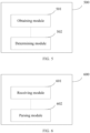
- FIG. 5 is a schematic structural diagram of an apparatus for determining a transmission parameter of an uplink channel according to an embodiment of this application. As shown in FIG. 5 , the apparatus mainly includes an obtaining module 501 and a determining module 502.
- the obtaining module 501 is configured to obtain configuration information; and the determining module 502 is configured to determine, according to the configuration information and detected first target downlink control information DCI, a transmission parameter of a target uplink channel scheduled by the first target DCI, where the configuration information is used to indicate any one of the following: SRS resource sets configured for different DCI formats, where the SRS resource set is used for codebook-based transmission or non-codebook-based transmission; a first instruction associated with a first resource, where the first resource includes at least one of the following: a control resource set, search space, and a DCI format; parameter information of the different DCI formats, where the parameter information includes at least one of the following: whether a target field exists, whether a second one field of the target field exists, and a size of the target field; and a configured grant.
- SRS resource sets configured for different DCI formats
- the SRS resource set is used for codebook-based transmission or non-codebook-based transmission
- a first instruction associated with a first resource where the first resource includes
- the SRS resource sets configured for the different DCI formats include at least one first SRS resource set configured for a first DCI format and/or at least one second SRS resource set configured for a second DCI format, for example, at least one first SRS resource set configured for DCI format 0_1 and/or at least one second SRS resource set configured for DCI format 0_2.
- the first index set is included in the second index set.
- the first index set is an index set of an SRS resource configured in the first SRS resource set
- the second index set is an index set of an SRS resource configured in the second SRS resource set.
- the first parameter of the first SRS resource set is the same as the first parameter of the second SRS resource set, where the first parameter is a parameter other than an index of an SRS resource in a configuration parameter of an SRS resource set.
- an index set of the at least one second SRS resource set is included in an index set of the at least one first SRS resource set.
- the configuration information further includes indication information indicating whether the second DCI format uses a plurality of SRS resource sets, and if the indication information indicates that the second DCI format uses the plurality of SRS resource sets, the terminal is indicated to determine, according to the at least one first SRS resource set, the at least one second SRS resource set configured for the second DCI format.
- determining module 502 determines, according to the configuration information and detected first target downlink control information DCI, a transmission parameter of a target uplink channel scheduled by the first target DCI includes:
- determining module 502 determines, according to the configuration information and detected first target downlink control information DCI, a transmission parameter of a target uplink channel scheduled by the first target DCI includes: in a case that the first target DCI is detected on the first resource associated with the first instruction, determining to transmit the target uplink channel by using a target transmission parameter, where the target transmission parameter includes at least one set of transmission parameters indicated by at least one target field in the first target DCI or at least one set of appointed transmission parameters.
- determining module 502 determines, according to the configuration information and detected first target downlink control information DCI, a transmission parameter of a target uplink channel scheduled by the first target DCI includes: in a case that the first target DCI is detected on a first resource that is not associated with the first instruction, determining to transmit the target uplink channel by using a target transmission parameter, where the target transmission parameter includes one set of transmission parameters indicated by one target field in the first target DCI or one set of appointed transmission parameters.
- the target transmission parameter includes one set of transmission parameters associated with a target SRS resource set, where the target SRS resource set is one of a plurality of SRS resource sets configured for the first target DCI.
- the target SRS resource set is an SRS resource set with a minimum identifier in the plurality of SRS resource sets configured for the first target DCI.
- the parameter information of the different DCI formats includes parameter information of a third DCI format and parameter information of a fourth DCI format, for example, parameter information of DCI format 0_1 and parameter information of DCI format 0_2.
- the parameter information of the different DCI formats includes parameter information of a fifth DCI format and parameter information of a sixth DCI format, for example, parameter information of DCI format 1_1 and parameter information of DCI format 1_2.
- determining module 502 determines, according to the configuration information and detected first target downlink control information DCI, a transmission parameter of a target uplink channel scheduled by the first target DCI includes:
- that the determining module 502 determines, according to the target parameter information, the transmission parameter of the target uplink channel scheduled by the first target DCI includes:
- the parameter information may further include a correspondence between each code point of the target field and indication information and/or an activated target code point.
- determining module 502 determines, according to the configuration information and detected first target downlink control information DCI, a transmission parameter of a target uplink channel scheduled by the first target DCI includes: in a case that a format of the first target DCI is a predetermined DCI format and the target uplink channel scheduled by the first target DCI is a PUSCH corresponding to the configured grant, determining the transmission parameter of the target uplink channel according to a target resource and a repetition parameter in the configured grant.
- the predetermined DCI format includes DCI format 0_0
- determining module 502 determines the transmission parameter of the target uplink channel according to a target resource and a repetition parameter in the configured grant includes:
- the target resource includes:
- the one target spatial relationship is a spatial relationship with a minimum index value in at least one spatial relationship of the target resource, or the one target spatial relationship is determined based on a target reference signal, where the target reference signal is a reference signal corresponding to a target transmission configuration indicator TCI state associated with the target resource; and the one target path loss reference signal is an associated path loss reference signal in the spatial relationship with the minimum index value in the at least one spatial relationship of the target resource; or the one target path loss reference signal is determined based on the target reference signal.
- the target TCI state is a TCI state with a minimum index value in a TCI state associated with the target resource.
- the target reference signal is a reference signal corresponding to a quasi co-location QCL of a type D associated with the target TCI state.
- the determining module 502 determines the transmission parameter of the target uplink channel according to a target resource and a repetition parameter in the configured grant further includes: in a case that the value of the repetition parameter is 1, determining that a power control parameter of the target uplink channel is a first set of power control parameters configured in the configured grant or one set of power control parameters with a minimum index value configured in the configured grant, or determining that a power control parameter of the target uplink channel is associated with one set of power control parameters of an SRS resource set with a minimum index value in SRS resource sets configured in the configured grant.
- that the obtaining module 501 obtains configuration information includes: obtaining the parameter information of the different DCI formats configured by higher layer signaling for the terminal.
- the higher layer signaling includes RRC signaling and/or a MAC CE.
- the transmission parameter includes at least one of the following:
- the target field includes at least one of the following:
- the apparatus for determining a transmission parameter of an uplink channel in this embodiment of this application may be an apparatus, or may be a component, an integrated circuit, or a chip in a terminal.
- the apparatus may be a mobile terminal, or a non-mobile terminal.
- the mobile terminal may include but is not limited to the types of the terminal 11 listed above, and the non-mobile terminal may be a server, a network attached storage (Network Attached Storage, NAS), a personal computer (personal computer, PC), a television (television, TV), an automated teller machine, or a self-service machine. This is not specifically limited in the embodiments of this application.
- the apparatus for determining a transmission parameter of an uplink channel in this embodiment of this application may be an apparatus with an operating system.
- the operating system may be an Android (Android) operating system, an iOS operating system, or another possible operating system. This is not specifically limited in this embodiment of this application.
- the apparatus for determining a transmission parameter of an uplink channel provided in this embodiment of this application can implement the processes implemented by the terminal in the method embodiments in FIG. 2 to FIG. 4 , and achieve a same technical effect. To avoid repetition, details are not described herein again.
- FIG. 6 is a schematic structural diagram of a DCI parsing apparatus according to an embodiment of this application.
- the apparatus 600 mainly includes a receiving module 601 and a parsing module 602.
- the receiving module 601 is configured to receive second target DCI, where a target BWP indicated by a BWP indicator field in the second target DCI is not an activated BWP; and the parsing module 602 is configured to parse a target field in the second target DCI according to a quantity X of target fields included in the second target DCI and a quantity Y of target fields that need to be interpreted for scheduling the target BWP, where X and Y are integers greater than or equal to 0.
- that the parsing module 602 parses a target field in the second target DCI according to a quantity X of target fields included in the second target DCI and a quantity Y of target fields that need to be interpreted for scheduling the target BWP includes: in a case that X is greater than or equal to Y, parsing the first or last Y target fields in the second target DCI.
- that the parsing module 602 parses the first or last Y target fields in the second target DCI includes: in a case that Y is 0, not parsing the target field in the second target DCI.
- that the parsing module 602 parses a target field in the second target DCI according to a quantity X of target fields included in the second target DCI and a quantity Y of target fields that need to be interpreted for scheduling the target BWP includes:
- that the parsing module 602 parses a target field in the second target DCI according to a quantity X of target fields included in the second target DCI and a quantity Y of target fields that need to be interpreted for scheduling the target BWP further includes: in a case that X is 0, assuming, by the terminal, that there is no corresponding target field on the target BWP.
- that the parsing module 602 parses a target field in the second target DCI according to a quantity X of target fields included in the second target DCI and a quantity Y of target fields that need to be interpreted for scheduling the target BWP includes:
- the X valid SRS resource sets include one of the following:
- that the parsing module 602 parses a target field in the second target DCI according to a quantity X of target fields included in the second target DCI and a quantity Y of target fields that need to be interpreted for scheduling the target BWP includes:
- the target SRS resource set is one SRS resource set with a minimum index value in the plurality of SRS resource sets configured on the target BWP or activated BWP.
- the parsing module 602 before parsing the target field in the second target DCI, the parsing module 602 is further configured to:
- the target field includes at least one of the following:
- an SRI field in the second target DCI correspondingly indicates an SRS resource in an SRS resource set configured on the activated BWP.
- FIG. 7 is a schematic structural diagram of a scheduling apparatus according to an embodiment of this application. As shown in FIG. 7 , the apparatus 700 mainly includes a configuration module 701 and a scheduling module 702.
- the configuration module 701 is configured to send configuration information to a terminal; and the scheduling module 702, configured to send first target DCI to the terminal according to the configuration information and a transmission parameter of a to-be-scheduled target uplink channel, where the first target DCI is used to schedule the target uplink channel, where the configuration information is used to indicate any one of the following: sounding reference signal SRS resource sets configured for different DCI formats, where the SRS resource set is used for codebook-based transmission or non-codebook-based transmission; a first instruction associated with a first resource, where the first resource includes at least one of the following: a control resource set, search space, and a DCI format; parameter information of the different DCI formats, where the parameter information includes at least one of the following: whether a target field exists, whether a second one field of the target field exists, and a size of the target field; and a configured grant.
- SRS resource sets configured for different DCI formats
- the SRS resource set is used for codebook-based transmission or non-codebook-based transmission
- the SRS resource sets configured for the different DCI formats include at least one first SRS resource set configured for a first DCI format and/or at least one second SRS resource set configured for a second DCI format, for example, at least one first SRS resource set configured for DCI format 0_1 and/or at least one second SRS resource set configured for DCI format 0_2.
- that the scheduling module 702 sends first target DCI to the terminal according to the configuration information and a transmission parameter of a scheduled target uplink channel includes:
- that the scheduling module 702 sends first target DCI to the terminal according to the configuration information and a transmission parameter of a scheduled target uplink channel includes:
- the parameter information of the different DCI formats includes parameter information of a third DCI format and parameter information of a fourth DCI format, for example, parameter information of DCI format 0_1 and parameter information of DCI format 0_2.
- the parameter information of the different DCI formats includes parameter information of a fifth DCI format and parameter information of a sixth DCI format, for example, parameter information of DCI format 1_1 and parameter information of DCI format 1_2.
- that the scheduling module 702 sends first target DCI to the terminal according to the configuration information and a transmission parameter of a scheduled target uplink channel includes:
- the target uplink channel is indicated to be transmitted by using an appointed transmission parameter; and in a case that the target parameter information indicates that the second one field of the target field does not exist, the target field in the first target DCI indicates all transmission parameters of the target uplink channel, or the target field in the first target DCI indicates a part of transmission parameters of the target uplink channel.
- the parameter information may further include a correspondence between each code point of the target field and indication information and/or an activated target code point.
- that the scheduling module 702 sends first target DCI to the terminal according to the configuration information and a transmission parameter of a scheduled target uplink channel includes: in a case that the target uplink channel is a PUSCH corresponding to the configured grant, sending the first target DCI in a predetermined DCI format to the terminal, where the predetermined DCI format includes DCI format 0_0.
- an embodiment of this application further provides a communication device 800, including a processor 801, a memory 802, and a program or an instruction that is stored in the memory 802 and that can be run on the processor 801.
- a communication device 800 including a processor 801, a memory 802, and a program or an instruction that is stored in the memory 802 and that can be run on the processor 801.
- the communication device 800 is a terminal
- the program or the instruction is executed by the processor 801 to implement the processes of the foregoing embodiment of the method 200 or the processes of the foregoing embodiment of the method 300, and a same technical effect can be achieved.
- the communication device 800 is a network side device
- the program or the instruction is executed by the processor 801 to implement the processes of the foregoing embodiment of the method 300, and a same technical effect can be achieved. To avoid repetition, details are not described herein again.
- An embodiment of this application further provides a terminal, including a processor and a communication interface, where the processor is configured to implement the processes of the embodiment of foregoing method 200, or the processes of the foregoing embodiment of the method 300, and the communication interface is configured to communicate with a network side device.
- This terminal embodiment corresponds to the foregoing method embodiment on the terminal side.
- Each implementation process and implementation of the foregoing method embodiment may be applicable to this terminal embodiment, and a same technical effect can be achieved.
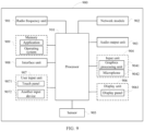
- FIG. 9 is a schematic structural diagram of hardware of a terminal according to an embodiment of this application.
- the terminal 900 includes but is not limited to components such as a radio frequency unit 901, a network module 902, an audio output unit 903, an input unit 904, a sensor 905, a display unit 906, a user input unit 907, an interface unit 908, a memory 909, and a processor 910.
- the terminal 900 may further include a power supply (such as a battery) that supplies power to each component.
- the power supply may be logically connected to the processor 910 by using a power supply management system, to implement functions such as charging and discharging management, and power consumption management by using the power supply management system.
- the terminal structure shown in FIG. 9 constitutes no limitation on the terminal, and the terminal may include more or fewer components than those shown in the figure, or combine some components, or have different component arrangements. Details are not described herein.
- the input unit 904 may include a graphics processing unit (Graphics Processing Unit, GPU) 9041 and a microphone 9042, and the graphics processing unit 9041 processes image data of a still picture or a video obtained by an image capture apparatus (such as a camera) in a video capture mode or an image capture mode.
- the display unit 906 may include a display panel 9061.
- the display panel 9061 may be configured in a form such as a liquid crystal display or an organic light-emitting diode.
- the user input unit 907 includes a touch panel 9071 and another input device 9072.
- the touch panel 9071 is also referred to as a touchscreen.
- the touch panel 9071 may include two parts: a touch detection apparatus and a touch controller.
- the another input device 9072 may include but is not limited to a physical keyboard, a functional button (such as a volume control button or a power on/off button), a trackball, a mouse, and a joystick. Details are not described herein.
- the radio frequency unit 901 receives downlink data from a network side device and then sends the downlink data to the processor 910 for processing; and sends uplink data to the network side device.
- the radio frequency unit 901 includes but is not limited to an antenna, at least one amplifier, a transceiver, a coupler, a low noise amplifier, a duplexer, and the like.
- the memory 909 may be configured to store a software program or an instruction and various data.
- the memory 909 may mainly include a program or instruction storage area and a data storage area.
- the program or instruction storage area may store an operating system, and an application or an instruction required by at least one function (for example, a sound playing function or an image playing function).
- the memory 909 may include a high-speed random access memory, and may further include a non-transient memory.
- the non-transient memory may be a read-only memory (Read-Only Memory, ROM), a programmable read-only memory (Programmable ROM, PROM), an erasable programmable read-only memory (Erasable PROM, EPROM), an electrically erasable programmable read-only memory (Electrically EPROM, EEPROM), or a flash memory, for example, at least one disk storage component, a flash memory component, or another non-transient solid-state storage component.
- ROM Read-Only Memory
- PROM programmable read-only memory
- Erasable PROM Erasable PROM
- EPROM electrically erasable programmable read-only memory
- EEPROM electrically erasable programmable read-only memory
- flash memory for example, at least one disk storage component, a flash memory component, or another non-transient solid-state storage component.
- the processor 910 may include one or more processing units.
- an application processor and a modem processor may be integrated into the processor 910.
- the application processor mainly processes an operating system, a user interface, an application, an instruction, or the like.
- the modem processor mainly processes wireless communications, for example, a baseband processor. It can be understood that, alternatively, the modem processor may not be integrated into the processor 910.
- the processor 910 is configured to: obtain configuration information; and determine, according to the configuration information and detected first target downlink control information DCI, a transmission parameter of a target uplink channel scheduled by the first target DCI, where the configuration information is used to indicate any one of the following:
- the processor 910 is configured to: receive second target DCI, where a target BWP indicated by a BWP indicator field in the second target DCI is not an activated BWP; and parse a target field in the second target DCI according to a quantity X of target fields included in the second target DCI and a quantity Y of target fields that need to be interpreted for scheduling the target BWP, where X and Y are integers greater than or equal to 0.
- This terminal embodiment corresponds to the foregoing method embodiment on the terminal.
- Each implementation process and implementation of the foregoing method embodiment may be applicable to this terminal embodiment, and a same technical effect can be achieved.
- An embodiment of this application further provides a network side device, including a processor and a communication interface, where the processor is configured to implement the processes of the embodiment of the method 400, and the communication interface is configured to communicate with a terminal.
- This network side device embodiment corresponds to the foregoing method embodiment on the network side device.
- Each implementation process and implementation of the foregoing method embodiment may be applicable to this network side device embodiment, and a same technical effect can be achieved.
- a network device 1000 includes an antenna 1001, a radio frequency apparatus 1002, and a baseband apparatus 1003.
- the antenna 1001 is connected to the radio frequency apparatus 1002.
- the radio frequency apparatus 1002 receives information by using the antenna 1001, and sends the received information to the baseband apparatus 1003 for processing.
- the baseband apparatus 1003 processes to-be-sent information, and sends the information to the radio frequency apparatus 1002.
- the radio frequency apparatus 1002 processes the received information and then sends the information by using the antenna 1001.
- the frequency band processing apparatus may be located in the baseband apparatus 1003.
- the method performed by the network side device in the foregoing embodiment may be implemented in the baseband apparatus 1003.
- the baseband apparatus 1003 includes a processor 1004 and a memory 1005.
- the baseband apparatus 1003 may include, for example, at least one baseband board, where a plurality of chips are disposed on the baseband board. As shown in FIG. 10 , one chip is, for example, the processor 1004, which is connected to the memory 1005, so as to invoke a program in the memory 1005 to perform operations of the network device shown in the foregoing method embodiment.
- the baseband apparatus 1003 may further include a network interface 1006, configured to exchange information with the radio frequency apparatus 1002.
- the interface is a common public radio interface (common public radio interface, CPRI for short).
- the network side device in this embodiment of the present invention further includes an instruction or a program that is stored in the memory 1005 and that can be run on the processor 1004.
- the processor 1004 invokes the instruction or the program in the memory 1005 to perform the method performed by the modules shown in FIG. 7 , and a same technical effect is achieved. To avoid repetition, details are not described herein again.
- An embodiment of this application further provides a readable storage medium.
- the readable storage medium stores a program or an instruction, and the program or the instruction is executed by a processor to implement the processes of the foregoing embodiment of the method for determining a transmission parameter of an uplink channel, the processes of the foregoing DCI parsing method embodiment, or the processes of the foregoing scheduling method embodiment, and a same technical effect can be achieved. To avoid repetition, details are not described herein again.
- the processor is a processor in the terminal in the foregoing embodiment.
- the readable storage medium includes a computer-readable storage medium, such as a computer read-only memory (Read-only Memory, ROM), a random access memory (Random Access Memory, RAM), a magnetic disk, or an optical disc.
- An embodiment of this application further provides a chip.
- the chip includes a processor and a communication interface, the communication interface is coupled to the processor, and the processor is configured to run a program or an instruction to implement the processes of the foregoing embodiment of the method for determining a transmission parameter of an uplink channel, the processes of the foregoing DCI parsing method embodiment, or the processes of the foregoing scheduling method embodiment, and a same technical effect can be achieved. To avoid repetition, details are not described herein again.
- the chip mentioned in this embodiment of this application may also be referred to as a system-level chip, a system chip, a chip system, or an on-chip system chip.
- An embodiment of this application further provides a computer program/program product.
- the computer program/program product is stored in a non-transient storage medium, and the program/program product is executed by at least one processor to implement the processes of the foregoing embodiment of the method for determining a transmission parameter of an uplink channel, the processes of the foregoing DCI parsing method embodiment, or the processes of the foregoing scheduling method embodiment, and a same technical effect can be achieved. To avoid repetition, details are not described herein again.
- the method in the foregoing embodiment may be implemented by software in addition to a necessary universal hardware platform or by hardware only. In most circumstances, the former is a preferred implementation. Based on such an understanding, the technical solutions of this application essentially or the part contributing to the prior art may be implemented in a form of a computer software product.
- the computer software product is stored in a storage medium (such as a ROM/RAM, a hard disk, or an optical disc), and includes several instructions for instructing a terminal (which may be a mobile phone, a computer, a server, an air conditioner, a network device, or the like) to perform the methods described in the embodiments of this application.
Landscapes
- Engineering & Computer Science (AREA)
- Signal Processing (AREA)
- Computer Networks & Wireless Communication (AREA)
- Mobile Radio Communication Systems (AREA)
Applications Claiming Priority (2)
| Application Number | Priority Date | Filing Date | Title |
|---|---|---|---|
| CN202110477883.5A CN115278716A (zh) | 2021-04-29 | 2021-04-29 | 上行信道的传输参数方法、终端及网络侧设备 |
| PCT/CN2022/088740 WO2022228341A1 (zh) | 2021-04-29 | 2022-04-24 | 上行信道的传输参数方法、终端及网络侧设备 |
Publications (2)
| Publication Number | Publication Date |
|---|---|
| EP4333486A1 true EP4333486A1 (de) | 2024-03-06 |
| EP4333486A4 EP4333486A4 (de) | 2024-11-06 |
Family
ID=83745812
Family Applications (1)
| Application Number | Title | Priority Date | Filing Date |
|---|---|---|---|
| EP22794812.2A Pending EP4333486A4 (de) | 2021-04-29 | 2022-04-24 | Verfahren zur übertragung von parametern eines uplink-kanals, endgerät und netzwerkseitige vorrichtung |
Country Status (4)
| Country | Link |
|---|---|
| US (1) | US20240237024A9 (de) |
| EP (1) | EP4333486A4 (de) |
| CN (1) | CN115278716A (de) |
| WO (1) | WO2022228341A1 (de) |
Families Citing this family (5)
| Publication number | Priority date | Publication date | Assignee | Title |
|---|---|---|---|---|
| CN115735343B (zh) * | 2021-06-29 | 2025-05-06 | 北京小米移动软件有限公司 | 上行传输方法、装置、设备及可读存储介质 |
| CN118074870A (zh) * | 2022-11-11 | 2024-05-24 | 维沃移动通信有限公司 | 信息确定方法、装置及通信设备 |
| CN121397745A (zh) * | 2023-02-15 | 2026-01-23 | Oppo广东移动通信有限公司 | 无线通信的方法、终端设备和网络设备 |
| WO2024182942A1 (zh) * | 2023-03-03 | 2024-09-12 | 北京小米移动软件有限公司 | 一种通信方法、装置及存储介质 |
| WO2025035326A1 (zh) * | 2023-08-11 | 2025-02-20 | 北京小米移动软件有限公司 | 信息确定方法、终端、网络设备、通信设备和存储介质 |
Family Cites Families (14)
| Publication number | Priority date | Publication date | Assignee | Title |
|---|---|---|---|---|
| CN107872267A (zh) * | 2016-09-28 | 2018-04-03 | 北京信威通信技术股份有限公司 | 一种波束跟踪的方法及装置 |
| EP3518454B1 (de) * | 2017-12-01 | 2021-08-04 | LG Electronics Inc. | Verfahren für uplink-übertragung und -empfang in einem drahtloskommunikationssystem und vorrichtung dafür |
| KR102480797B1 (ko) * | 2017-12-15 | 2022-12-22 | 광동 오포 모바일 텔레커뮤니케이션즈 코포레이션 리미티드 | 채널 자원 집합의 지시 방법 및 장치, 컴퓨터 저장 매체 |
| US10560901B2 (en) * | 2018-02-16 | 2020-02-11 | Lenovo (Singapore) Pte. Ltd. | Method and apparatus having power control for grant-free uplink transmission |
| CN110351859B (zh) * | 2018-04-02 | 2022-02-25 | 华为技术有限公司 | 资源指示值的获取方法及装置 |
| JP7243739B2 (ja) * | 2018-06-01 | 2023-03-22 | 富士通株式会社 | Bwp指示の設定方法、装置及び通信システム |
| WO2020060340A1 (ko) * | 2018-09-21 | 2020-03-26 | 엘지전자 주식회사 | 무선 통신 시스템에서 상향링크 송수신을 수행하기 위한 방법 및 이를 위한 장치 |
| CN115695099A (zh) * | 2019-02-01 | 2023-02-03 | 华为技术有限公司 | 用于探测参考信号传输和接收的设备、网络和方法 |
| US11265818B2 (en) * | 2019-03-29 | 2022-03-01 | FG Innovation Company Limited | Method of closed-loop power control in multi-panel transmission and related device |
| WO2020206581A1 (zh) * | 2019-04-08 | 2020-10-15 | Oppo广东移动通信有限公司 | 传输信号的方法、终端设备和网络设备 |
| EP4102757B1 (de) * | 2020-02-04 | 2024-08-28 | LG Electronics Inc. | Verfahren und vorrichtung zur wiederholten übertragung von uplink-kanälen in einem drahtloskommunikationssystem |
| US20230070564A1 (en) * | 2020-03-20 | 2023-03-09 | Lg Electronics Inc. | Method and apparatus for transmitting and receiving signal on basis of spatial parameter in wireless communication system |
| CN116349185A (zh) * | 2020-12-11 | 2023-06-27 | 中兴通讯股份有限公司 | 多发送接收点信令 |
| WO2023056148A1 (en) * | 2021-09-30 | 2023-04-06 | Qualcomm Incorporated | Communications associated with different sounding reference signal resource sets |
-
2021
- 2021-04-29 CN CN202110477883.5A patent/CN115278716A/zh active Pending
-
2022
- 2022-04-24 EP EP22794812.2A patent/EP4333486A4/de active Pending
- 2022-04-24 WO PCT/CN2022/088740 patent/WO2022228341A1/zh not_active Ceased
-
2023
- 2023-10-30 US US18/497,146 patent/US20240237024A9/en active Pending
Also Published As
| Publication number | Publication date |
|---|---|
| EP4333486A4 (de) | 2024-11-06 |
| US20240237024A9 (en) | 2024-07-11 |
| CN115278716A (zh) | 2022-11-01 |
| US20240137951A1 (en) | 2024-04-25 |
| WO2022228341A1 (zh) | 2022-11-03 |
Similar Documents
| Publication | Publication Date | Title |
|---|---|---|
| EP4262307A1 (de) | Pusch-übertragungsverfahren und -vorrichtung sowie vorrichtung und speichermedium | |
| EP4333486A1 (de) | Verfahren zur übertragung von parametern eines uplink-kanals, endgerät und netzwerkseitige vorrichtung | |
| EP4258786B1 (de) | Pusch-planungsübertragungsverfahren, endgerät und netzwerkseitige vorrichtung | |
| CN115603838B (zh) | 信道状态信息csi上报处理方法、接收方法及相关设备 | |
| US20230362924A1 (en) | Transmission processing method and related device | |
| US20230261836A1 (en) | Resource configuration method, apparatus, device, and readable storage medium | |
| EP4319361A1 (de) | Verfahren zur abbildung von berichten über kanalzustandsinformationen (csi), endgerät und netzwerkseitige vorrichtung | |
| US20240147565A1 (en) | Tci state indication method and apparatus, terminal, and network side device | |
| US20240179781A1 (en) | Method and Device for Transmitting Reference Signal | |
| US20240031941A1 (en) | Power control parameter indication method, terminal, and network side device | |
| EP4383905A1 (de) | Verfahren zur anzeige von downlink-steuerinformationen sowie verfahren und vorrichtung zur bestimmung der rangfolge von uplink-kanalübertragungen | |
| US12507254B2 (en) | Information determining method, information sending method, terminal, and network side device | |
| EP4280667A1 (de) | Verfahren zum senden von kanalinformationen, verfahren zum empfangen von kanalinformationen und zugehörige vorrichtung | |
| CN114390554B (zh) | 信道状态信息确定方法、上报设置确定方法、装置及相关设备 | |
| US20240322971A1 (en) | Srs resource configuration method and apparatus, terminal, and network side device | |
| CN114390657A (zh) | 功率确定方法、装置、终端及可读存储介质 | |
| US20240023108A1 (en) | Method and apparatus for determining pucch resource, and terminal | |
| US20260089551A1 (en) | Format Determining Method, User Equipment (UE), and Non-Transitory Readable Storage Medium | |
| US20250055652A1 (en) | Beam information determination method, and terminal, and network-side device | |
| EP4462709A1 (de) | Verfahren und vorrichtung zur rückkopplung von kanalzustandsinformationen (csi), endgerät und netzwerkseitige vorrichtung | |
| US20240267906A1 (en) | Joint scheduling method and device | |
| US20240406969A1 (en) | Information activation method, terminal, and network side device | |
| EP4344271A1 (de) | Informationsübertragungsverfahren und -vorrichtung, informationserfassungsverfahren und -vorrichtung und kommunikationsvorrichtung | |
| WO2022206908A1 (zh) | 上行传输方法、装置、终端、网络侧设备和存储介质 | |
| CN115087120A (zh) | 控制信令接收方法、发送方法、装置、终端及网络侧设备 |
Legal Events
| Date | Code | Title | Description |
|---|---|---|---|
| STAA | Information on the status of an ep patent application or granted ep patent |
Free format text: STATUS: THE INTERNATIONAL PUBLICATION HAS BEEN MADE |
|
| PUAI | Public reference made under article 153(3) epc to a published international application that has entered the european phase |
Free format text: ORIGINAL CODE: 0009012 |
|
| STAA | Information on the status of an ep patent application or granted ep patent |
Free format text: STATUS: REQUEST FOR EXAMINATION WAS MADE |
|
| 17P | Request for examination filed |
Effective date: 20231103 |
|
| AK | Designated contracting states |
Kind code of ref document: A1 Designated state(s): AL AT BE BG CH CY CZ DE DK EE ES FI FR GB GR HR HU IE IS IT LI LT LU LV MC MK MT NL NO PL PT RO RS SE SI SK SM TR |
|
| DAV | Request for validation of the european patent (deleted) | ||
| DAX | Request for extension of the european patent (deleted) | ||
| A4 | Supplementary search report drawn up and despatched |
Effective date: 20241008 |
|
| RIC1 | Information provided on ipc code assigned before grant |
Ipc: H04L 5/00 20060101ALI20241001BHEP Ipc: H04W 24/02 20090101AFI20241001BHEP |