EP4333669B1 - Appareil pour la mise en forme des cheveux - Google Patents
Appareil pour la mise en forme des cheveux Download PDFInfo
- Publication number
- EP4333669B1 EP4333669B1 EP22727147.5A EP22727147A EP4333669B1 EP 4333669 B1 EP4333669 B1 EP 4333669B1 EP 22727147 A EP22727147 A EP 22727147A EP 4333669 B1 EP4333669 B1 EP 4333669B1
- Authority
- EP
- European Patent Office
- Prior art keywords
- strip
- hair
- arms
- lock
- contact surface
- Prior art date
- Legal status (The legal status is an assumption and is not a legal conclusion. Google has not performed a legal analysis and makes no representation as to the accuracy of the status listed.)
- Active
Links
Images


Classifications
-
- A—HUMAN NECESSITIES
- A45—HAND OR TRAVELLING ARTICLES
- A45D—HAIRDRESSING OR SHAVING EQUIPMENT; EQUIPMENT FOR COSMETICS OR COSMETIC TREATMENTS, e.g. FOR MANICURING OR PEDICURING
- A45D1/00—Curling-tongs, i.e. tongs for use when hot; Curling-irons, i.e. irons for use when hot; Accessories therefor
- A45D1/02—Curling-tongs, i.e. tongs for use when hot; Curling-irons, i.e. irons for use when hot; Accessories therefor with means for internal heating, e.g. by liquid fuel
- A45D1/04—Curling-tongs, i.e. tongs for use when hot; Curling-irons, i.e. irons for use when hot; Accessories therefor with means for internal heating, e.g. by liquid fuel by electricity
-
- A—HUMAN NECESSITIES
- A45—HAND OR TRAVELLING ARTICLES
- A45D—HAIRDRESSING OR SHAVING EQUIPMENT; EQUIPMENT FOR COSMETICS OR COSMETIC TREATMENTS, e.g. FOR MANICURING OR PEDICURING
- A45D1/00—Curling-tongs, i.e. tongs for use when hot; Curling-irons, i.e. irons for use when hot; Accessories therefor
- A45D1/06—Curling-tongs, i.e. tongs for use when hot; Curling-irons, i.e. irons for use when hot; Accessories therefor with two or more jaws
-
- A—HUMAN NECESSITIES
- A45—HAND OR TRAVELLING ARTICLES
- A45D—HAIRDRESSING OR SHAVING EQUIPMENT; EQUIPMENT FOR COSMETICS OR COSMETIC TREATMENTS, e.g. FOR MANICURING OR PEDICURING
- A45D2/00—Hair-curling or hair-waving appliances ; Appliances for hair dressing treatment not otherwise provided for
- A45D2/001—Hair straightening appliances
Definitions
- the present invention relates to an apparatus for shaping hair, in particular for hair relaxing and/or straightening operations.
- hair straighteners consist of two arms that are connected together with the aid of a hinge that makes it possible to open and close said arms and of a heating device comprising at least one heating element arranged on the arms.
- a heating device comprising at least one heating element arranged on the arms.
- the heating element may be combined with at least one comb, which might or might not be a heating comb, which allows the strands of hair to be separated as they pass between the arms and friction to be applied in order to bring about more uniform results.
- An apparatus of this type is, for example, described in application FR 2 940 894 , the apparatus comprising a friction bar that is mounted movably with respect to the straightening surface and able to interact with a friction counter-bar when the arms are in the closed position, thereby defining a tensile region that creates a tensile force greater than the tensile force created by the treatment region as the apparatus is moved over a lock of hair.
- WO 2017/089152 discloses a device for shaping hair comprising a heating plate for heating the hair, a temperature sensor and a heat control circuit, the surface of the heating plate potentially comprising a silicone strip. Similar devices are described in CN 207152182 and CN 207270050 .
- WO 2015/088058 discloses a device for shaping hair comprising two arms, each having a contact surface, one contact surface having two strips made of a friction material.
- the known apparatuses are not entirely satisfactory when it comes to obtaining sufficient friction between the lock of hair and the heating device during shaping which leads to insufficient hair alignment.
- the invention aims to meet this need entirely or in part, and it does so by virtue of an apparatus for shaping hair according to claim 1.
- the movement of the apparatus relative to the lock of hair may be slowed down which allows more uniform and more effective straightening of the hair to be obtained.
- hair encompasses human or corresponding animal, but preferably human, keratin fibers and also synthetic fibers known as "extensions" which are sometimes added to an individual's natural head of hair by various means, especially by adhesive bonding, in order for example to modify the appearance of an individual's natural head of hair and the synthetic or non-synthetic fibers of a wig.
- contact surface is a surface for treating hair, preferably a straightening surface, for example formed by a straightening plate, which is advantageously a heating plate, as will be described hereinafter.
- Each treatment surface is intended to come into contact with at least one lock of hair during the hair treatment.
- the contact surfaces are preferably planar and arranged parallel to one another in the moved-together configuration.
- the contact surfaces may be made of an inorganic material, for example a metal or a ceramic, being made, for example, of anodized aluminium or of aluminium with a ceramic surface treatment.
- Said at least one strip is preferably not movable relative to the contact surface to which it is attached. It should be noted that it has a specific elasticity depending on the friction material used. It preferably has a continuous and planar friction surface, in particular one that is free of reliefs, for example free of teeth.
- the silicone elastomer might or might not be fluorinated.
- the silicone elastomer is, in particular, chosen from the group formed of vinyl methyl silicone (VMQ), poly vinyl methyl silicone (PVMQ), fluoro vinyl methyl silicone (FVMQ) and methyl silicone (MQ), preferably vinyl methyl silicone (VMQ).
- the fluoroelastomer belongs, for example, to the ranges marketed under the names Viton ® by Chemours Company, Tecnoflon ® by Solvay and Kalrez ® by DuPont.
- the perfluoroelastomer belongs, for example, to the ranges marketed under the names Tecnoflon ® and Kalrez ® .
- These materials which may form the friction material are elastic. They are also able to withstand continuous use at more than 230°C.
- Said at least one strip is preferably free of any material other than the friction material.
- said at least one strip may consist entirely of a synthetic polymer and be free of any mineral or multi-mineral element or infrared powder.
- the friction material preferably has a Shore A hardness of between 40 and 90 Shore A, in particular substantially equal to 70 Shore A.
- the clamping force of the arms in the moved-together configuration i.e. the pinching force exerted when using the apparatus on a lock of hair, this lock of hair being engaged between the arms in the moved-together configuration, may be between 10 N and 30 N, being, for example, equal to 10 N, 20 N or 30 N.
- the tension of the lock of hair may be between 9.5 N and 12.5 N for a clamping force of 30 N and a temperature of said at least one surface equal to 200°C.
- the speed at which the lock of hair passes through the apparatus is preferably about 1.8 cm/s.
- the width of said at least one strip may be between 0.5 mm and 10 mm, in particular between 1 mm and 5 mm, preferably between 1 mm and 2 mm, preferably being substantially equal to 1.9 mm.
- the friction surface of said at least one strip advantageously covers an area smaller than 50% of the surface area of the contact surface to which it is attached, preferably smaller than 40%, more preferably smaller than 20%.
- one of the contact surfaces comprises a single strip and the other of the contact surfaces comprises two strips that are arranged so as to flank the single strip in the moved-together configuration of the arms.
- the single strip may be arranged equidistantly from the lateral edges of the contact surface to which it is attached, and the two strips are respectively attached with the same distance from the lateral edges of the contact surface to which they are attached.
- each contact surface comprises two strips.
- At least one of the contact surfaces comprises two strips, these extend advantageously parallel to one another.
- Said at least one strip may extend heightwise along an axis perpendicular to the contact surface to which it is attached.
- Said at least one strip may take the shape of a parallelepiped of substantially square or rectangular cross section.
- said at least one strip has a substantially trapezoidal cross section, with a width of the friction surface of said at least one strip intended to come into contact with the lock of hair that is smaller than the width of the surface opposite thereto.
- the edges of said at least one strip each form, with the friction surface, an angle of between 5° and 30°, preferably between 10° and 20°, the angle formed between one of the edges and the friction surface of said at least one strip preferably being equal to the angle formed between the other of the edges and the friction surface of said at least one strip.
- each contact surface may comprise at least one groove for accommodating said at least one strip.
- said at least one groove may have a substantially trapezoidal cross section, with a width that decreases from the bottom in the direction of the opening of the groove.
- the exterior shape of the portion of the strip that is accommodated in the groove may be designed to conform to the shape of the groove. The strip may slip into the groove or be force-fitted into the groove.
- said at least one strip is attached to the contact surface as an overthickness, in which case the contact surface may be free of any relief for accommodating said at least one strip.
- a surface treatment with the deposition of a thin layer of friction material may be envisaged to produce such a strip.
- said at least one strip may be attached to the contact surface by bonding the friction material or by way of a coating process.
- coating process is a process comprising the spraying of a deposit in non-polymerized form onto the contact surface and then heating or irradiating this deposit so as to polymerize it into the friction material in order to attach it to the contact surface.
- the apparatus is preferably a straightening iron.
- the apparatus preferably comprises a heating device so as to heat said at least one contact surface, which is a heating surface.
- the overall heating power of the apparatus may be between 50 W and 200 W.
- the apparatus may comprise a steam-issuing device that may be used, in particular, when passing the lock of hair between the contact surfaces.
- the apparatus may comprise one or more combs, which might or might not be removable.
- Another subject of the invention is a process for treating hair implementing the apparatus as defined above and comprising the steps of introducing a lock of hair between the arms in the spaced-apart configuration thereof, applying a clamping force to the arms so that they transition to the moved-together configuration while pinching the lock of hair and exerting a clamping force, and then moving the apparatus relative to the lock of hair, preferably in the direction from the roots to the ends of the hair.
- the process may comprise reiterating the steps mentioned until the hair, or a portion thereof, has been treated.
- the treatment process is preferably implemented at a temperature of said at least one contact surface, which is a heating surface, of between 120°C and 235°C, better between 150°C and 230°C.
- the clamping force of the arms in the moved-together configuration while pinching the lock of hair may be between 10 N and 30 N, being, for example, equal to 10 N, 20 N or 30 N.
- the tension of the lock of hair may be between 9.5 N and 12.5 N for a clamping force of 30 N and a temperature of said at least one heating contact surface equal to 200°C.
- the speed at which the lock of hair passes through the apparatus is preferably about 1.8 cm/s.
- the treatment process may be carried out with or without the use of at least one cosmetic composition which may be applied before, during or after the shaping of the hair, but preferably before.
- the treatment process advantageously consists in straightening the hair.
- the treatment process may further be implemented in the presence of steam, for example originating from the apparatus.
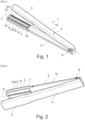
- a handpiece 2 of an example of a hair-shaping apparatus 1 is shown in Figures 1 to 12 .
- This handpiece 2 has two arms 3 and 4 which are movable with respect to one another between a spaced-apart configuration visible in Figure 1 for introducing a lock of hair between them and a moved-together configuration, shown in Figures 10 to 12 , for treating the lock of hair.
- the arm 3 forms an upper arm and the arm 4 forms a lower arm in this example. They are connected to one another at one end by a joint 8, the handpiece 2 thus forming tongs.
- the arms 3 and 4 define respective half-handles 10 and 11 on which the user may press in order to move the arms 3 and 4 together so as to make them go from the spaced-apart configuration to the moved-together configuration.
- An elastic return member (not visible) is preferably provided to return the arms 3 and 4 to the spaced-apart configuration, this elastic return member being, for example, a spring arranged around a pin of the joint 8.
- the invention is not limited to one particular way of connecting the arms 3 and 4 together. They may be made movable in another way without departing from the scope of the present invention. However, the presence of a joint is greatly preferred for the ergonomics that it affords.
- the arms 3 and 4 each bear, in an end portion opposite the joint 8, a contact surface 5 and 6, respectively.
- the contact surfaces 5 and 6 face one another, being arranged opposite one another. At least one of the contact surfaces, in the example illustrated both contact surfaces 5 and 6, is (are) heating surfaces.
- the contact surfaces 5 and 6 form an outer surface of two plates 7 and 9, respectively, of substantially rectangular shape which will be presented further below.
- the arms 3 and 4 extend along respective longitudinal axes X and Y.
- the contact surfaces 5 and 6 take the shape of a rectangle that is elongated along these same respective longitudinal axes X and Y.
- the arms 3 and 4 define between them, with the contact surfaces 5 and 6, a region for treating the hair, said region being intended to receive a lock of hair to be treated, the handpiece 2 being moved along said lock of hair during the treatment, for example in the direction from the root to the end of the hair.
- the direction of movement of the handpiece 2 over the hair is preferably substantially perpendicular to the arms 3 and 4.
- the handpiece 2 may be connected, on the joint 8 side, by a line (not visible in the example in question) to a base station (not shown) that is fixed during the treatment and is connected to the mains, or may be connected directly to the mains.
- This base station supplies power to the handpiece 2 and may also carry out additional functions of processing electrical signals received from the handpiece 2.
- the line that connects the handpiece 2 to the base station may thus comprise various electrical conductors.
- a user interface (not shown in the figures) may be present on the handpiece 2 so as to allow the user, for example, to start up or not to start up certain components thereof.
- At least one strip 12 made of a friction material is attached to each of the contact surfaces 5 and 6 so as to protrude from the contact surface 5 or 6 to which it is attached by a height H (visible in Figure 4 and also in Figure 11 ), which is strictly greater than 0 mm even when the arms 3 and 4 are in the moved-together configuration, as can be seen in particular in Figures 11 and 12 , and smaller than 2 mm.
- Said at least one strip 12 attached to one of the contact surfaces 5 or 6 is arranged so as to be offset with respect to said at least one strip 12 attached to the other of the contact surfaces 6 or 5 when the arms 3 and 4 are in the moved-together configuration, as can be seen in particular in Figures 11 and 12 .
- the contact surface 5 comprises a single strip 12a (visible in Figure 2 in particular) while the contact surface 6 comprises two strips 12b and 12c (visible in Figures 1 and 12 , among others), which are arranged on either side of the strip 12a when the arms 3 and 4 are in the moved-together position.
- the strips 12b and 12c are arranged close to the lateral edges 13 of the contact surface 6, equidistantly therefrom.
- the strip 12a is arranged at the centre of the contact surface 5.
- the friction material forming the strips 12 is a silicone elastomer, in this instance vinyl methyl silicone known by the abbreviation VMQ.
- This friction material has a Shore A hardness of 70 Shore A.
- the width of the strips 12 is, in this embodiment, the same for the three strips 12a, 12b and 12c and is equal, in this example, to 1.88 mm.
- each strip 12 extends along an axis parallel to the longitudinal axis of the arm 3 or 4.
- Each strip 12 has a friction surface 23 of rectilinear longitudinal axis, in this example rectangular in shape, and extends over the entire length of the contact surface 5 or 6 to which it is attached.
- the contact surfaces 5 and 6 are planar around the one or more strips 12.
- each contact surface 5 or 6 comprises one or two grooves 14 extending longitudinally from one longitudinal edge 15 to the other longitudinal edge 16 of the contact surface 5 or 6.
- Each groove 14 forms a recessed relief and is intended to accommodate a strip 12.
- the number of grooves 14 in a contact surface is equal to the number of strips present on this contact surface, preferably one or two per contact surface.
- the grooves 14 have a substantially trapezoidal cross section, as more clearly visible in Figure 4 , with a width that decreases from the bottom 29 of the groove 14 in the direction of the opening 17 of the groove 14.
- Each strip 12 is substantially trapezoidal in shape and/or conforms to the substantially trapezoidal shape of the groove 14 in which it is accommodated, projecting from the opening 17 of the groove by a height H, protruding with respect to the corresponding contact surface 5 or 6, as explained above.
- the lateral edges 21 and 22 of the strip 12 each form, with the friction surface 23 of the strip, an angle ⁇ and ⁇ of between 10° and 20° in this example, these two angles ⁇ and ⁇ being equal to one another in the example illustrated.
- the trapezium in which the substantially trapezoidal shape of each strip 12 is inscribed is an isosceles trapezium in this example.
- angles of the substantially trapezoidal shapes formed by the strips 12 are slightly rounded, in this example in a more pronounced manner on the bottom 29 side of the groove 14.
- the width of the friction surface 23 of the strip is smaller than the width of the opposite surface 24, in contact with the bottom 29 of the groove 14.
- Each strip 12 extends heightwise along an axis Z perpendicular to the contact surface 5 or 6 to which it is attached, as illustrated, for example, in Figure 4 .
- the friction surface 23 of the or each strip 12 occupies an area smaller than 20% of the surface area of the contact surface 5 or 6 to which it is attached.
- each strip 12 should not occupy an area greater than 20% of the surface area of the contact surface 5 or 6.
- the total area occupied by these two strips 12 could not occupy an area greater than 40% of the total area of the contact surface.
- the strips 12b and 12c are parallel to one another in this example.
- the strips 12 extend heightwise perpendicularly to the longitudinal axis X or Y of the arm 3 or 4, corresponding to the longitudinal axis of the contact surface 5 or 6, respectively.
- the strips 12 may be squashed to a certain extent, thereby decreasing the height H, which nonetheless remains strictly greater than 0 mm, preferably greater than 0.5 mm, when the arms 3 and 4 are in the moved-together configuration.
- the contact surface 6 forms the outer surface of the plate 9 forming, in this example, a heating device 25 of the apparatus, more clearly visible in Figures 4 , 6 and 7 , comprising a compartment 26 accommodating a heating element 27 which is electrically connected using electrical wires (not visible), via the line mentioned above, to the base station or to the mains.
- the compartment 26 and the heating element 27 both take, in this example, a parallelepipedal shape and extend parallel, as can be seen, to the contact surface 6.
- the heating device 25 takes, as can be seen in Figure 4 , a shape that allows the incorporation of the grooves 14, with lateral edges 13 of the contact surface 6 that are rectilinear over most of the contact surface 6 but which are rounded moving away from the contact surface 6, and through-openings 28 which flank the compartment 26.
- the through-openings 28 could be replaced with a solid material instead without departing from the scope of the invention.
- the contact surface 5 forms the outer surface of the plate 7 forming, in this example, a heating device 30, similar to the heating device 25, comprising a compartment 31 accommodating a heating element 32 which is electrically connected using electrical wires 33 (visible in Figure 8 ), via the line mentioned above, to the base station or to the mains.
- the compartment 31 and the heating element 32 both take, in this example, a parallelepipedal shape and extend parallel, as can be seen, to the contact surface 5.
- the heating device 30 takes, as can be seen in Figure 8 , a shape that allows the incorporation of the groove 14, with lateral edges 13 of the contact surface 5 that are rectilinear over most of the contact surface 5 but which are rounded moving away from the contact surface 5, and through-openings 34 which flank the compartment 31.
- the through-openings 34 could be replaced with a solid material instead without departing from the scope of the invention.
- a lock of hair is introduced between the arms 3 and 4 in the spaced-apart configuration thereof, a clamping force which may be between 10 N and 30 N, for example 30 N, is applied to the arms 3 and 4 via the half-handles 10 and 11 so as to move the arms 3 and 4 to the moved-together configuration while pinching the lock of hair.
- the apparatus 1 is moved relative to the lock of hair, preferably in the direction from the roots to the ends of the hair. Needless to say, these steps may be reiterated with other locks of hair until the hair, or a portion thereof, has been treated.
- the temperature of the heating contact surfaces 5 and 6 is, for example, equal to 200°C.
- the tension of the lock of hair, with the presence of the strips 12, is between 9.5 N and 12.5 N for a clamping force of 30 N.
- the temperature of said at least one contact surface is equal to 200°C.
- the speed at which the lock of hair passes through the apparatus is about 1.8 cm/s. For a treated hair length of 27 cm, the speed of movement will be about 15 s.
- each contact surface 5 and 6 comprises two strips 12, these being arranged in such a way that, when the arms 3 and 4 are in the moved-together configuration, the two strips 12 attached to the contact surface 5 are not superposed onto the strips 12 attached to the contact surface 6.
- the distance from one strip 12 to the closest lateral edge 13 of the contact surface is different from the distance from the other strip 12 to the closest lateral edge 13 of the contact surface, whichever contact surface 5 or 6 is considered.
- the strips 12 are not located equidistantly from the lateral edges 13 closest to this contact surface.
- the one or more strips 12 may take a different shape, for example a sinusoidal shape, without departing from the scope of the invention.
- the strip 12 may take, in cross section, a rectangular shape, for example, as illustrated in Figure 14 .
- the apparatus may be designed to apply steam and/or a cosmetic product to the hair.
- the friction material may be a fluoroelastomer or a perfluoroelastomer.
- the presence of the strips 12 made of a silicone elastomer, fluoroelastomer or perfluoroelastomer friction material of the apparatus according to the invention makes it possible to obtain satisfactory hair alignment, a smooth hair appearance in terms of ends and length as sought, as well as hair manageability and a smooth feel, which are desired.
Landscapes
- Brushes (AREA)
- Hair Curling (AREA)
Claims (13)
- Appareil (1) pour la mise en forme des cheveux, comprenant :- deux bras (3, 4) pouvant se déplacer l'un par rapport à l'autre et pouvant prendre une configuration écartée pour introduire une mèche de cheveux entre eux et une configuration rapprochée pour traiter la mèche de cheveux, les bras (3, 4) étant mobiles le long de la mèche dans cette configuration rapprochée,- deux surfaces de contact (5, 6) portées respectivement par les deux bras (3, 4), disposées face à face, au moins une des surfaces de contact (5, 6) étant une surface chauffante,- au moins une bande (12, 12a, 12b, 12c, 12d) en un matériau de friction comprenant un élastomère de silicone, un fluoroélastomère ou un perfluoroélastomère, et fixée à chacune des surfaces de contact (5, 6) de sorte à faire saillie de la surface de contact (5 ; 6) à laquelle elle est fixée d'une hauteur (H) qui est strictement supérieure à 0 mm, même dans la configuration rapprochée des bras (3, 4), et inférieure à 2 mm,- l'une des surfaces de contact (5 ; 6) comprenant une bande unique (12, 12a) et l'autre des surfaces de contact (6 ; 5) comprenant deux bandes (12, 12b, 12c) qui sont disposées de sorte à flanquer la bande unique (12, 12a) dans la configuration rapprochée des bras (3, 4).
- Appareil (1) selon la revendication 1, la hauteur (H) de saillie de ladite au moins une bande (12, 12a, 12b, 12c, 12d) étant comprise entre 0,5 et 2 mm, de préférence étant sensiblement égale à 1 mm, dans la configuration écartée des bras (3, 4).
- Appareil (1) selon la revendication 1 ou 2, l'élastomère de silicone étant choisi parmi le vinyl-méthyl-silicone (VMQ), le poly vinyl-méthyl-silicone (PVMQ), le fluoro vinyl-méthyl-silicone (FVMQ) et le méthyl-silicone (MQ), de préférence étant le vinyl-méthyl-silicone (VMQ).
- Appareil (1) selon l'une quelconque des revendications précédentes, la largeur de ladite au moins une bande (12, 12a, 12b, 12c, 12d) étant comprise entre 0,5 mm et 10 mm, en particulier entre 1 mm et 5 mm.
- Appareil (1) selon la revendication précédente, la largeur de ladite au moins une bande (12, 12a, 12b, 12c, 12d) étant comprise entre 1 et 2 mm, de préférence étant sensiblement égale à 1,9 mm.
- Appareil (1) selon l'une quelconque des revendications précédentes, ledit matériau de friction présentant une dureté Shore A comprise entre 40 et 90 Shore A, en particulier sensiblement égale à 70 Shore A.
- Appareil (1) selon l'une quelconque des revendications précédentes, ladite au moins une bande (12, 12a, 12b, 12c, 12d) présentant une surface de friction (23) d'axe longitudinal rectiligne, en particulier de forme rectangulaire, s'étendant longitudinalement selon un axe parallèle à un axe longitudinal (X ; Y) de la surface de contact (5 ; 6) à laquelle elle est fixée.
- Appareil (1) selon l'une quelconque des revendications précédentes, la surface de friction (23) de ladite au moins une bande (12, 12a, 12b, 12c, 12d) couvrant une surface inférieure à 50 % de la surface de la surface de contact (5 ; 6) à laquelle elle est attachée, de préférence inférieure à 40 %, de préférence encore inférieure à 20 %.
- Appareil (1) selon l'une quelconque des revendications précédentes, la bande unique (12, 12a) étant disposée à égale distance des bords latéraux (13) de la surface de contact (5) à laquelle elle est fixée, et les deux bandes (12, 12b, 12c) étant respectivement fixées à la même distance des bords latéraux (13) de la surface de contact (6) à laquelle elles sont fixées.
- Appareil (1) selon l'une quelconque des revendications précédentes, ladite au moins une bande (12, 12a, 12b, 12c, 12d) présentant une section transversale sensiblement trapézoïdale, la largeur de la surface de friction (23) de ladite au moins une bande (12, 12a, 12b, 12c, 12d) destinée à entrer en contact avec la mèche de cheveux étant inférieure à la largeur de la surface qui lui est opposée.
- Appareil (1) selon la revendication précédente, les bords (21, 22) de ladite au moins une bande (12, 12a, 12b, 12c, 12d) formant chacun, avec la surface de friction (23), un angle (α, β) compris entre 5° et 30°, de préférence entre 10° et 20°, l'angle (α) formé entre l'un des bords (21) et la surface de friction (23) de ladite au moins une bande (12, 12a, 12b, 12c, 12d) étant de préférence égal à l'angle (β) formé entre l'autre des bords (22) et la surface de friction (23) de ladite au moins une bande (12, 12a, 12b, 12c, 12d).
- Appareil (1) selon l'une quelconque des revendications précédentes, chaque surface de contact (5, 6) comprenant au moins une rainure (14) destinée à recevoir ladite au moins une
bande (12, 12a, 12b, 12c, 12d), ladite au moins une rainure (14) présentant de préférence une section transversale sensiblement trapézoïdale, avec une largeur qui diminue à partir de la partie inférieure (29) en direction de l'ouverture (17) de la rainure (14). - Procédé de traitement des cheveux mettant en œuvre l'appareil (1) selon l'une quelconque des revendications précédentes, comprenant les étapes consistant à :- introduire une mèche de cheveux entre les bras (3, 4) dans leur configuration écartée,- appliquer une force de fermeture aux bras (3, 4) de sorte qu'ils passent à la configuration rapprochée tout en pinçant la mèche de cheveux et en exerçant une force de serrage, et- déplacer l'appareil par rapport à la mèche de cheveux, de préférence dans la direction des racines vers les pointes des cheveux.
Applications Claiming Priority (2)
| Application Number | Priority Date | Filing Date | Title |
|---|---|---|---|
| FR2104839A FR3122556B1 (fr) | 2021-05-07 | 2021-05-07 | Appareil de mise en forme d’une chevelure |
| PCT/EP2022/061948 WO2022233921A1 (fr) | 2021-05-07 | 2022-05-04 | Appareil de mise en forme de cheveux |
Publications (3)
| Publication Number | Publication Date |
|---|---|
| EP4333669A1 EP4333669A1 (fr) | 2024-03-13 |
| EP4333669B1 true EP4333669B1 (fr) | 2025-01-15 |
| EP4333669C0 EP4333669C0 (fr) | 2025-01-15 |
Family
ID=76159664
Family Applications (1)
| Application Number | Title | Priority Date | Filing Date |
|---|---|---|---|
| EP22727147.5A Active EP4333669B1 (fr) | 2021-05-07 | 2022-05-04 | Appareil pour la mise en forme des cheveux |
Country Status (8)
| Country | Link |
|---|---|
| US (1) | US20240206610A1 (fr) |
| EP (1) | EP4333669B1 (fr) |
| JP (1) | JP2024516862A (fr) |
| KR (1) | KR20240004973A (fr) |
| CN (1) | CN117279540A (fr) |
| ES (1) | ES3009724T3 (fr) |
| FR (1) | FR3122556B1 (fr) |
| WO (1) | WO2022233921A1 (fr) |
Families Citing this family (2)
| Publication number | Priority date | Publication date | Assignee | Title |
|---|---|---|---|---|
| USD1108708S1 (en) * | 2020-11-12 | 2026-01-06 | Unil Electronics Corporation | Iron for straightening hair |
| USD1064406S1 (en) * | 2024-01-17 | 2025-02-25 | Gamma Piu' S.R.L. | Hair straightening iron |
Family Cites Families (46)
| Publication number | Priority date | Publication date | Assignee | Title |
|---|---|---|---|---|
| JPS63161902A (ja) * | 1986-12-26 | 1988-07-05 | 瀧前 豊作 | 縮毛矯正用アイロン |
| US5377700A (en) * | 1993-07-30 | 1995-01-03 | Harris; Ilise H. | Eyelash curler |
| JP3000262B2 (ja) * | 1996-05-23 | 2000-01-17 | 豊作 瀧前 | 縮れ毛矯正アイロン |
| JP3060279U (ja) * | 1998-07-23 | 1999-08-17 | 株式会社クレイツ | ストレ−トパ−マ用ヘアアイロン |
| US6223753B1 (en) * | 1999-10-04 | 2001-05-01 | Zhen-Xing Lo | Manual hairdressing and styling device |
| US6105585A (en) * | 2000-01-07 | 2000-08-22 | Thomas; Marsha | Combination eyelash curler and eyeliner applicator |
| US6789551B2 (en) * | 2001-05-08 | 2004-09-14 | Irina Iosilevich | Eyelash separating, curling and coloring apparatus |
| KR200284378Y1 (ko) * | 2002-03-08 | 2002-08-10 | 박강수 | 가열된 유체를 열원으로 하는 고데기 |
| KR100596704B1 (ko) * | 2005-03-02 | 2006-07-10 | 최영범 | 완충부재가 부착된 고대기 |
| JP4665716B2 (ja) * | 2005-10-26 | 2011-04-06 | パナソニック電工株式会社 | ヘアスタイリング用超音波振動装置 |
| GB2469768A (en) | 2005-11-18 | 2010-10-27 | Jemella Ltd | Electric hair iron with voltage control means |
| KR100766871B1 (ko) * | 2006-10-30 | 2007-10-15 | 박국철 | 고데기 |
| US20080223387A1 (en) * | 2007-03-12 | 2008-09-18 | Julemont Pierre L M | Hair straightening and styling appliance |
| ATE543405T1 (de) * | 2007-12-19 | 2012-02-15 | Tenacta Group Spa | Frisiergerät |
| KR100858028B1 (ko) * | 2008-04-17 | 2008-09-10 | 불루세라믹 주식회사 | 머리 미용기구 |
| US8567415B2 (en) * | 2008-08-04 | 2013-10-29 | Tenacta Group S.P.A. | Hair styling apparatus |
| FR2940893B1 (fr) | 2009-01-15 | 2012-12-21 | Seb Sa | Appareil de coiffure |
| KR101093394B1 (ko) * | 2009-03-10 | 2011-12-14 | 최영범 | 헤어 아이론 |
| JP2010233830A (ja) * | 2009-03-31 | 2010-10-21 | Kureitsu:Kk | ヘアーアイロン |
| KR100979136B1 (ko) * | 2009-11-26 | 2010-09-02 | (주) 에스엠세라믹 | 머리 미용기구 |
| IT1398942B1 (it) * | 2010-03-17 | 2013-03-28 | Tenacta Group Spa | Apparecchiatura elettrica per modellare i capelli |
| GB2477834B (en) * | 2010-08-31 | 2012-02-01 | Jemella Ltd | Hair styling appliance |
| KR200456707Y1 (ko) * | 2011-05-17 | 2011-11-14 | 주종현 | 헤어 매직기 |
| US9138038B2 (en) * | 2011-05-20 | 2015-09-22 | Spectrum Brands, Inc. | Hair styling apparatus having hair-protection function |
| DE102011077138A1 (de) * | 2011-06-07 | 2012-12-13 | BSH Bosch und Siemens Hausgeräte GmbH | Haarglätter |
| US11160346B2 (en) * | 2012-05-01 | 2021-11-02 | Jemella Limited | Hair styling appliance |
| WO2015088058A1 (fr) * | 2013-12-10 | 2015-06-18 | 최명표 | Fer à lisser |
| JP6336597B2 (ja) * | 2013-12-19 | 2018-06-06 | ザ プロクター アンド ギャンブル カンパニー | ファイバー材料の成形装置 |
| FR3023138B1 (fr) * | 2014-07-02 | 2018-07-13 | L'oreal | Appareil de coiffure pour former des boucles de tailles differentes |
| FR3031023B1 (fr) * | 2014-12-30 | 2018-03-30 | L'oreal | Recharge pour insertion dans un dispositif de traitement de la chevelure par basculement |
| US9936783B2 (en) * | 2015-01-23 | 2018-04-10 | Harold Harris | Method and device for straightening hair |
| CN108289538A (zh) * | 2015-11-25 | 2018-07-17 | 皇家飞利浦有限公司 | 头发造型设备 |
| US20180255897A1 (en) * | 2017-03-13 | 2018-09-13 | Thomas G. Kelley | Combination comb and flat iron device |
| CN207152182U (zh) | 2017-08-22 | 2018-03-30 | 温州市拉博电器有限公司 | 一种硅胶垫美发器 |
| CN207270050U (zh) | 2017-09-19 | 2018-04-27 | 东莞富美康电器科技有限公司 | 直发夹 |
| US20190183223A1 (en) * | 2017-12-15 | 2019-06-20 | Kelly Parrotto | Hair Straightening Device |
| US20190183225A1 (en) * | 2017-12-15 | 2019-06-20 | L'oreal | Hair treatment tool and spacing accessory |
| US20200015562A1 (en) * | 2018-03-19 | 2020-01-16 | Charlotte Levingston-Johnson | Cordless hair styling apparatus and method of use |
| US20200138161A1 (en) * | 2018-11-06 | 2020-05-07 | Kiesque, Incorporated | Apparatus and method for curling eyelashes |
| US11064779B2 (en) * | 2019-01-28 | 2021-07-20 | Pui Yan Chung | Eyelash shaping implements |
| US20200323325A1 (en) * | 2019-04-15 | 2020-10-15 | Kiss Nail Products, Inc. | Applicator for makeup product |
| FR3102652B1 (fr) * | 2019-11-05 | 2021-11-12 | Oreal | Procédé de traitement de la chevelure |
| US11445792B1 (en) * | 2020-05-26 | 2022-09-20 | Sheryl-Lee Walters | Hair dry blower |
| US20220160094A1 (en) * | 2020-11-20 | 2022-05-26 | Bjx2, Llc | Eyelash application tool |
| GB2607065B (en) * | 2021-05-27 | 2024-09-04 | Dyson Technology Ltd | A hair styling appliance |
| US20240298770A1 (en) * | 2023-03-07 | 2024-09-12 | iBeauty Brands, Inc. | Apparatus and method for styling hair |
-
2021
- 2021-05-07 FR FR2104839A patent/FR3122556B1/fr active Active
-
2022
- 2022-05-04 CN CN202280033717.9A patent/CN117279540A/zh active Pending
- 2022-05-04 EP EP22727147.5A patent/EP4333669B1/fr active Active
- 2022-05-04 WO PCT/EP2022/061948 patent/WO2022233921A1/fr not_active Ceased
- 2022-05-04 KR KR1020237041884A patent/KR20240004973A/ko not_active Ceased
- 2022-05-04 ES ES22727147T patent/ES3009724T3/es active Active
- 2022-05-04 US US18/288,428 patent/US20240206610A1/en not_active Abandoned
- 2022-05-04 JP JP2023568371A patent/JP2024516862A/ja active Pending
Also Published As
| Publication number | Publication date |
|---|---|
| JP2024516862A (ja) | 2024-04-17 |
| US20240206610A1 (en) | 2024-06-27 |
| FR3122556B1 (fr) | 2023-06-02 |
| EP4333669C0 (fr) | 2025-01-15 |
| FR3122556A1 (fr) | 2022-11-11 |
| EP4333669A1 (fr) | 2024-03-13 |
| KR20240004973A (ko) | 2024-01-11 |
| WO2022233921A1 (fr) | 2022-11-10 |
| ES3009724T3 (en) | 2025-03-31 |
| CN117279540A (zh) | 2023-12-22 |
Similar Documents
| Publication | Publication Date | Title |
|---|---|---|
| EP4333669B1 (fr) | Appareil pour la mise en forme des cheveux | |
| EP3240452B1 (fr) | Dispositif commandant l'application d'un produit pour le traitement des cheveux | |
| US20200196694A1 (en) | Applicators for applying eyelash extensions and methods for use and manufacture thereof | |
| RU2687806C2 (ru) | Парикмахерское устройство для создания локонов различного размера | |
| US20020189628A1 (en) | Eyelash separating, curling and coloring apparatus | |
| US6062231A (en) | Device for applying a hair product to tresses | |
| EP3389431B1 (fr) | Dispositif de traitement de cheveux ayant un élément chauffant | |
| CN101677666A (zh) | 用于毛发处理组合物的施用装置 | |
| US20170340084A1 (en) | Refill for a device for treating the hair, having a coupling relief | |
| JP4090182B2 (ja) | 毛髪化粧料塗布用具 | |
| EP4510882B1 (fr) | Dispositif de traitement capillaire | |
| GB2584066A (en) | A hair treatment device | |
| EP4510884B1 (fr) | Dispositif de traitement capillaire | |
| RU2682284C1 (ru) | Устройство для обработки волос, содержащее заправочный элемент, вставляемый сбоку | |
| US11344094B2 (en) | Refill for inserting into a device for treating the hair by pivoting | |
| KR200402222Y1 (ko) | 헤어용 아이롱과 분리결합이 가능한 모발 정렬을 위한 빗 | |
| US20210085051A1 (en) | Process for treating hair fibres | |
| JP2003070523A (ja) | ヘアーアイロン | |
| EP4510885A1 (fr) | Dispositif de traitement capillaire | |
| WO2003061426A1 (fr) | Peigne ou brosse a cheveux et methode de coiffure | |
| AU2002240720B2 (en) | Hair comb or brush apparatus and hair styling method | |
| ITMI20110858A1 (it) | Piastra per capelli ed accessorio per piastra per capelli | |
| AU2002240720A1 (en) | Hair comb or brush apparatus and hair styling method |
Legal Events
| Date | Code | Title | Description |
|---|---|---|---|
| STAA | Information on the status of an ep patent application or granted ep patent |
Free format text: STATUS: UNKNOWN |
|
| STAA | Information on the status of an ep patent application or granted ep patent |
Free format text: STATUS: THE INTERNATIONAL PUBLICATION HAS BEEN MADE |
|
| PUAI | Public reference made under article 153(3) epc to a published international application that has entered the european phase |
Free format text: ORIGINAL CODE: 0009012 |
|
| STAA | Information on the status of an ep patent application or granted ep patent |
Free format text: STATUS: REQUEST FOR EXAMINATION WAS MADE |
|
| 17P | Request for examination filed |
Effective date: 20231205 |
|
| AK | Designated contracting states |
Kind code of ref document: A1 Designated state(s): AL AT BE BG CH CY CZ DE DK EE ES FI FR GB GR HR HU IE IS IT LI LT LU LV MC MK MT NL NO PL PT RO RS SE SI SK SM TR |
|
| GRAP | Despatch of communication of intention to grant a patent |
Free format text: ORIGINAL CODE: EPIDOSNIGR1 |
|
| STAA | Information on the status of an ep patent application or granted ep patent |
Free format text: STATUS: GRANT OF PATENT IS INTENDED |
|
| DAV | Request for validation of the european patent (deleted) | ||
| DAX | Request for extension of the european patent (deleted) | ||
| INTG | Intention to grant announced |
Effective date: 20240809 |
|
| GRAS | Grant fee paid |
Free format text: ORIGINAL CODE: EPIDOSNIGR3 |
|
| GRAA | (expected) grant |
Free format text: ORIGINAL CODE: 0009210 |
|
| STAA | Information on the status of an ep patent application or granted ep patent |
Free format text: STATUS: THE PATENT HAS BEEN GRANTED |
|
| AK | Designated contracting states |
Kind code of ref document: B1 Designated state(s): AL AT BE BG CH CY CZ DE DK EE ES FI FR GB GR HR HU IE IS IT LI LT LU LV MC MK MT NL NO PL PT RO RS SE SI SK SM TR |
|
| REG | Reference to a national code |
Ref country code: CH Ref legal event code: EP Ref country code: GB Ref legal event code: FG4D |
|
| REG | Reference to a national code |
Ref country code: DE Ref legal event code: R096 Ref document number: 602022009625 Country of ref document: DE |
|
| REG | Reference to a national code |
Ref country code: IE Ref legal event code: FG4D |
|
| U01 | Request for unitary effect filed |
Effective date: 20250203 |
|
| U07 | Unitary effect registered |
Designated state(s): AT BE BG DE DK EE FI FR IT LT LU LV MT NL PT RO SE SI Effective date: 20250207 |
|
| REG | Reference to a national code |
Ref country code: ES Ref legal event code: FG2A Ref document number: 3009724 Country of ref document: ES Kind code of ref document: T3 Effective date: 20250331 |
|
| U20 | Renewal fee for the european patent with unitary effect paid |
Year of fee payment: 4 Effective date: 20250407 |
|
| PG25 | Lapsed in a contracting state [announced via postgrant information from national office to epo] |
Ref country code: RS Free format text: LAPSE BECAUSE OF FAILURE TO SUBMIT A TRANSLATION OF THE DESCRIPTION OR TO PAY THE FEE WITHIN THE PRESCRIBED TIME-LIMIT Effective date: 20250415 |
|
| PG25 | Lapsed in a contracting state [announced via postgrant information from national office to epo] |
Ref country code: PL Free format text: LAPSE BECAUSE OF FAILURE TO SUBMIT A TRANSLATION OF THE DESCRIPTION OR TO PAY THE FEE WITHIN THE PRESCRIBED TIME-LIMIT Effective date: 20250115 |
|
| PGFP | Annual fee paid to national office [announced via postgrant information from national office to epo] |
Ref country code: ES Payment date: 20250606 Year of fee payment: 4 |
|
| PG25 | Lapsed in a contracting state [announced via postgrant information from national office to epo] |
Ref country code: IS Free format text: LAPSE BECAUSE OF FAILURE TO SUBMIT A TRANSLATION OF THE DESCRIPTION OR TO PAY THE FEE WITHIN THE PRESCRIBED TIME-LIMIT Effective date: 20250515 Ref country code: NO Free format text: LAPSE BECAUSE OF FAILURE TO SUBMIT A TRANSLATION OF THE DESCRIPTION OR TO PAY THE FEE WITHIN THE PRESCRIBED TIME-LIMIT Effective date: 20250415 |
|
| PG25 | Lapsed in a contracting state [announced via postgrant information from national office to epo] |
Ref country code: HR Free format text: LAPSE BECAUSE OF FAILURE TO SUBMIT A TRANSLATION OF THE DESCRIPTION OR TO PAY THE FEE WITHIN THE PRESCRIBED TIME-LIMIT Effective date: 20250115 |
|
| PG25 | Lapsed in a contracting state [announced via postgrant information from national office to epo] |
Ref country code: GR Free format text: LAPSE BECAUSE OF FAILURE TO SUBMIT A TRANSLATION OF THE DESCRIPTION OR TO PAY THE FEE WITHIN THE PRESCRIBED TIME-LIMIT Effective date: 20250416 |
|
| PG25 | Lapsed in a contracting state [announced via postgrant information from national office to epo] |
Ref country code: SM Free format text: LAPSE BECAUSE OF FAILURE TO SUBMIT A TRANSLATION OF THE DESCRIPTION OR TO PAY THE FEE WITHIN THE PRESCRIBED TIME-LIMIT Effective date: 20250115 |
|
| U1N | Appointed representative for the unitary patent procedure changed after the registration of the unitary effect |
Representative=s name: IPSILON; FR |
|
| PG25 | Lapsed in a contracting state [announced via postgrant information from national office to epo] |
Ref country code: CZ Free format text: LAPSE BECAUSE OF FAILURE TO SUBMIT A TRANSLATION OF THE DESCRIPTION OR TO PAY THE FEE WITHIN THE PRESCRIBED TIME-LIMIT Effective date: 20250115 |
|
| PG25 | Lapsed in a contracting state [announced via postgrant information from national office to epo] |
Ref country code: SK Free format text: LAPSE BECAUSE OF FAILURE TO SUBMIT A TRANSLATION OF THE DESCRIPTION OR TO PAY THE FEE WITHIN THE PRESCRIBED TIME-LIMIT Effective date: 20250115 |
|
| PLBE | No opposition filed within time limit |
Free format text: ORIGINAL CODE: 0009261 |
|
| STAA | Information on the status of an ep patent application or granted ep patent |
Free format text: STATUS: NO OPPOSITION FILED WITHIN TIME LIMIT |
|
| REG | Reference to a national code |
Ref country code: CH Ref legal event code: L10 Free format text: ST27 STATUS EVENT CODE: U-0-0-L10-L00 (AS PROVIDED BY THE NATIONAL OFFICE) Effective date: 20251126 |
|
| REG | Reference to a national code |
Ref country code: CH Ref legal event code: H13 Free format text: ST27 STATUS EVENT CODE: U-0-0-H10-H13 (AS PROVIDED BY THE NATIONAL OFFICE) Effective date: 20251223 |
|
| 26N | No opposition filed |
Effective date: 20251016 |
|
| PG25 | Lapsed in a contracting state [announced via postgrant information from national office to epo] |
Ref country code: CH Free format text: LAPSE BECAUSE OF NON-PAYMENT OF DUE FEES Effective date: 20250531 |
|
| PG25 | Lapsed in a contracting state [announced via postgrant information from national office to epo] |
Ref country code: MC Free format text: LAPSE BECAUSE OF FAILURE TO SUBMIT A TRANSLATION OF THE DESCRIPTION OR TO PAY THE FEE WITHIN THE PRESCRIBED TIME-LIMIT Effective date: 20250115 |
|
| PGFP | Annual fee paid to national office [announced via postgrant information from national office to epo] |
Ref country code: GB Payment date: 20260313 Year of fee payment: 5 |
|
| PG25 | Lapsed in a contracting state [announced via postgrant information from national office to epo] |
Ref country code: IE Free format text: LAPSE BECAUSE OF NON-PAYMENT OF DUE FEES Effective date: 20250504 |