EP4334037B1 - Zufuhrniveausteuerungssystem und -verfahren - Google Patents
Zufuhrniveausteuerungssystem und -verfahren Download PDFInfo
- Publication number
- EP4334037B1 EP4334037B1 EP21745890.0A EP21745890A EP4334037B1 EP 4334037 B1 EP4334037 B1 EP 4334037B1 EP 21745890 A EP21745890 A EP 21745890A EP 4334037 B1 EP4334037 B1 EP 4334037B1
- Authority
- EP
- European Patent Office
- Prior art keywords
- sensor
- level
- storage container
- milling material
- additional
- Prior art date
- Legal status (The legal status is an assumption and is not a legal conclusion. Google has not performed a legal analysis and makes no representation as to the accuracy of the status listed.)
- Active
Links
Images

Classifications
-
- B—PERFORMING OPERATIONS; TRANSPORTING
- B02—CRUSHING, PULVERISING, OR DISINTEGRATING; PREPARATORY TREATMENT OF GRAIN FOR MILLING
- B02C—CRUSHING, PULVERISING, OR DISINTEGRATING IN GENERAL; MILLING GRAIN
- B02C11/00—Other auxiliary devices or accessories specially adapted for grain mills
- B02C11/04—Feeding devices
-
- B—PERFORMING OPERATIONS; TRANSPORTING
- B02—CRUSHING, PULVERISING, OR DISINTEGRATING; PREPARATORY TREATMENT OF GRAIN FOR MILLING
- B02C—CRUSHING, PULVERISING, OR DISINTEGRATING IN GENERAL; MILLING GRAIN
- B02C25/00—Control arrangements specially adapted for crushing or disintegrating
-
- B—PERFORMING OPERATIONS; TRANSPORTING
- B02—CRUSHING, PULVERISING, OR DISINTEGRATING; PREPARATORY TREATMENT OF GRAIN FOR MILLING
- B02C—CRUSHING, PULVERISING, OR DISINTEGRATING IN GENERAL; MILLING GRAIN
- B02C4/00—Crushing or disintegrating by roller mills
- B02C4/02—Crushing or disintegrating by roller mills with two or more rollers
- B02C4/06—Crushing or disintegrating by roller mills with two or more rollers specially adapted for milling grain
-
- B—PERFORMING OPERATIONS; TRANSPORTING
- B02—CRUSHING, PULVERISING, OR DISINTEGRATING; PREPARATORY TREATMENT OF GRAIN FOR MILLING
- B02C—CRUSHING, PULVERISING, OR DISINTEGRATING IN GENERAL; MILLING GRAIN
- B02C4/00—Crushing or disintegrating by roller mills
- B02C4/28—Details
- B02C4/286—Feeding devices
Definitions
- the present invention relates to a feed level control system for a grinding machine, such as a roller mill, and a grinding machine, such as a roller mill with a feed level control system according to the present invention.
- the invention further relates to a method for determining the level of milling material and controlling the level of milling material of a storage container of a grinding machine, such as a roller mill.
- the milling material is fed to a storage container, e.g. by gravity, and collected therein.
- the milling material is then metered with the aid of a discharge device, e.g. a feed roller, and conveyed into a milling gap in the milling unit.
- the fill level of the storage container is first set manually, e.g. by an operator, as the target level.
- Said target level has to be set in such a manner that, on the one hand, sufficient free buffer volume is available in the storage container (which means the target level should be set as low as possible), but on the other hand, the milling material can be dosed over the entire length of the rollers (which means the target level should be set as high as possible in order to ensure that sufficient material is fed to the rollers).
- a measuring device e.g. force sensor or capacitive sensor detects a deviation of the actual level from the target level during operation.
- a control device ensures that the discharge of material is adjusted so that the actual level corresponds as closely as possible to the target level.
- a sensor such as a force sensor, will not be able to detect the fill level precisely enough. Also, when such an amount of material is in the storage container that it forms a cone with an arch-like surface shape, a sensor will measure a fill level that is inconsistent with the actual fill level.
- WO 2020/025681 an automatic determination of the fill level of the storage container has been described. Said automatic determination is based on a force sensor in combination with a level sensor that is provided in an upper section of the storage container, preferably at a vertical distance from 20 to 60 cm from the force sensor.
- the system of WO 2020/025681 comprises a control unit that is designed to determine a first fill level of the storage container from the weight force determined by the force sensor.
- the control unit is further designed to determine a characteristic fill level curve based on the determined first fill level and a milling material level determined by the level sensor. Said determination is made when the milling material level has reached the position of the level sensor in the storage container.
- JP 2010-058115 A an inlet arrangement is described where two different sensors are used.
- a force sensor is provided in the lower third of the storage container.
- an ultrasonic sensor is provided on top of said storage container, which does not extend into the storage container to a level that corresponds to the level where the main sensor is provided.
- the present invention is related to an inlet arrangement for a grinding machine such as a roller mill comprising:
- the grinding machine e.g. roller mill
- the grinding machine comprises a main processing zone for milling of milling material (e.g. at least two rollers defining a roller gap between them).
- the main processing zone e.g. the roller gap
- milling material from the milling material outlet of the inlet arrangement.
- Such grinding machines for example roller mills, are generally known and need not be described here in detail.
- the present invention can be applied on many different grinding machines, but mainly on roller mills.
- the inlet arrangement further comprises at least one metering device arranged at the storage container for metering milling material into a milling gap of the grinding machine, preferably roller mill, through the milling material outlet.
- the metering device can simply be designed as a gap, wherein the discharge quantity can be adjusted, if necessary, by changing a gap width, e.g. with the aid of a throttle valve.
- the metering device may further comprise other elements which, for example, support the distribution of milling material in the storage container. These may comprise, for example, a conveying device such as a paddle or worm shaft.
- the metering device may also comprise a feed roller, which is designed to convey the milling material from the milling material outlet to the milling gap of the roller mill.
- a main sensor preferably force sensor
- said main sensor preferably force sensor is designated as the main sensor, since it provides for the principal signal reflecting the amount of milling material in the storage container.
- said main sensor, preferably force sensor may be a load cell or a piezoelectric sensor or a capacitive sensor.
- the full range of signals from this sensor are continuously or discontinuously detected and continuously or discontinuously forwarded to the control unit.
- the sensor is touchable, so that it is possible to generate signals by human interaction. This is useful for checking the function of the force sensor and/or its interaction with the control unit described below.
- the main sensor preferably force sensor
- the storage container can be connected to a force sensor, for example suspended from a force sensor or mounted on a force sensor.
- a force sensor for example suspended from a force sensor or mounted on a force sensor.
- the main sensor is arranged in the storage container, especially preferably in a lower region of the storage container.
- the main sensor is a force sensor which comprises an extension arm that protrudes into the storage container, preferably into a lower region of the storage container. More preferably, said lower region mentioned above is a lower third of the storage container. The lower the position of the force sensor in the storage container, the more milling material in the storage container will it be able to detect.
- the position of the lower end of said additional sensor, preferably level sensor, where said additional sensor, preferably level sensor, is provided at the storage container for operation may deviate from the level where the main sensor, preferably force sensor, is provided at the storage container by a small distance of 5 cm or less, preferably 2 cm or less, and most preferably 1 cm or less.
- additional sensor preferably 1 to 6, more preferably 1 to 4 additional sensors.
- additional sensors which may be preferably of the same kind as the level sensor described above, or alternatively sensors such as acoustic sensors, NIR sensors or X-Ray sensors, it may be possible to detect additional dimensions of the cone of milling material in the storage container, so as to further improve the measurement result.
- the control unit can be a dedicated control unit of the inlet arrangement, which is connected to a higher-level control unit, for example of a roller mill. This is particularly advantageous if the inlet arrangement is intended for retrofitting existing roller mills.
- the control unit can be implemented in a higher-level control unit, for example in the control unit of a roller mill or in a plant control system.
- the control unit may contain components for preprocessing the signals it obtains from the sensors, before the regulation process is carried out.
- control unit may contain one or more A/D converters for converting analog signals from the sensors (for example physical indicator signals such as electric current, voltage, or frequency) into digital signals. Any commonly used A/D converter may be employed in the control unit.
- A/D converter may be employed in the control unit.
- each of the sensors arranged in the inlet arrangement generates an analog signal, and that to each sensor there is attributed a respective A/D converter.
- two A/D converters are provided, one for the signal of the main sensor and one for the signal of the additional sensor.
- an offset procedure may be carried out.
- An offset procedure involves the correction of the offset from the sensor signal, preferably by subtracting a constant value from the sensor signal. Offset procedures are known and used, for example, for converting negative values into positive values.
- a scaling procedure involves a gain or attenuation of the sensor signals.
- scaling may be performed by multiplying the sensor signal with a constant value.
- Scaling procedures are known and used, for example, for amplifying signals.
- a filtering procedure may be carried out.
- a filtering procedure may be performed, for example, to reduce the noise of the sensor signal.
- a moving average filtering and/or an IIR-filter and/or a low pass-filter and/or a band pass-filter and/or a low pass-filter may be used in the control unit.
- one or more of the above processing operations may be carried out.
- the signals which have been preferably processed as described above, are transmitted to a calculation unit.
- a calculation unit Such calculation units are known and may be for example conventional computers, workstations etc. equipped with the necessary software.
- a sensor value for the main sensor preferably force sensor (i.e. the signal derived from the force signal which is the main sensor), is determined in dependence from the values detected by the one or more additional sensors, preferably level sensors.
- additional sensors preferably level sensors.
- two preferably processed signals are provided to the calculation unit, one for the signal of the main sensor and one for the signal of the additional sensor.
- Said calculation may involve a calibration of the signals provided by the main sensor, preferably force sensor, on the basis of the signals provided by the one or more additional sensors, preferably level sensors.
- said calculation may involve the calculation of calibration factors, level ranges, integrals, differential equations, or combinations thereof, for the main sensor, preferably force sensor, according to the signals derived from additional sensors, preferably level sensors.
- said calculation procedure can be carried out using a timer, a trigger threshold, a difference between the signals derived from the main sensor, preferably force sensor, and the additional sensors, preferably level sensors, and combinations thereof.
- the thus obtained signal value from the calculation unit is transmitted into a regulation unit, where the obtained signal value is compared with a setpoint level that may be provided by an operator, for example via an input signal or a computer interface.
- a regulation unit may be for example conventional computers, workstations etc. equipped with the necessary software.
- the setpoint level is defined as the level that should be reached by the milling material level measured by the sensors. It is a target level that can be determined automatically, or preferably is predetermined by an operator.
- the operator can for example provide a setpoint level by input of an analog signal, by input via a computer interface such as a keyboard or touchscreen, or by providing parameters necessary for determining the setpoint level, for example in a memory unit of the control unit.
- the obtained signal value i.e. the signal value derived from the sensors and obtained by preferably processing and subsequently calculation, as described above
- the setpoint level a deviation of the two values is identified, the obtained signal value is adjusted to the setpoint value.
- the regulation procedure may be selected from the group consisting of PID-Regulation, Artificial-Intelligence (AI) regulation and linear or non-linear control system regulation.
- PID-Regulation a controller integrated in a control loop acts on a controlled system in such a way that a variable to be controlled, i.e. the controlled variable, adjusts itself to the level of the selected reference variable (here the setpoint value) with the help of negative feedback, regardless of interference.
- PID-Regulation is well-known.
- Artificial-Intelligence (AI) regulation is also known and involves the use of self-learning, machine learning algorithms.
- Artificial intelligence is a generic term for the "artificial" generation of knowledge from experience: An artificial system learns from examples and can generalize them after the learning phase has ended. For this purpose, algorithms in machine learning build a statistical model that is based on training data.
- the regulation may also be a linear or non-linear control system regulation.
- a nonlinear system is a system in which a change of the output is not proportional to a change of the input.
- Nonlinear dynamical systems describing changes in variables over time, may appear chaotic, unpredictable, or counterintuitive, contrasting with much simpler linear systems.
- Such systems are also well-known and may involve a decentralized system control with SISO (Single Input Single Output) and/or MIMO (Multiple Input and Multiple Output).
- the signal level i.e. the signal value derived from the sensors and obtained by preferably processing and subsequently calculation, as described above
- a defined setpoint level i.e. the signal value derived from the sensors and obtained by preferably processing and subsequently calculation, as described above
- the levels of the main sensor, preferably force sensor, and the additional sensor(s), preferably level sensor(s), may be compared, and preferably the additional sensor, preferably a level sensor and more preferably a capacitive sensor, may be used to check if the level of said sensors is in an expected range.
- an output signal is thus generated that is transmitted, preferably via a D/A converter, to a machine control element.
- the D/A converter may be used to convert a digital value (here the output of the regulation procedure) into an analog (physical) signal (for example current, voltage, frequency), in order to operate an element of the inlet arrangement or the grinding machine, e.g. roller mill, for example an actuator.
- a digital value here the output of the regulation procedure
- an analog (physical) signal for example current, voltage, frequency
- said machine control element influences the transport (flow) of milling material out of the storage container.
- a motor with variable speed may be operated therewith in order to modify the speed of rotation of the rollers in a roller mill, therewith enhancing or decreasing the amount of milling material that is conveyed into the milling gap between the roller mills.
- an electromechanical or physical process may be initiated to turn or shift movable components of the inlet arrangement or a roller mill.
- the machine control element may operate the metering device of the inlet arrangement, by swiveling a throttle valve of the metering device.
- the control unit is connected or connectable to the machine control element. Said connections may be for example conventional electrical lines or a wireless or bluetooth connection.
- the present invention also related to a method for determining and controlling the level of milling material in a storage container for milling material of a grinding machine such as a roller mill, the storage container comprising at least one milling material inlet, at least one milling material outlet and at least one metering device for metering milling material into a milling gap of the grinding machine through the milling material outlet, the method comprising the following steps:
- the method can be performed as described above in detail with respect to the control element.
- the sensors continuously detect the milling material level in the storage container.
- This allows a continuous and precise regulation of the transport (flow) of the milling material out of the storage container, thus minimizing any fluctuation in the transport (flow) of the milling material by continuous operation of elements in the inlet arrangement and or the grinding machine, e.g. roller mill, that influence the transport (flow) of the milling material out of the storage container, for example a motor controlling the rotational speed of the roller mills or an actuator actuating a throttle valve in the metering device of the inlet arrangement.
- At least 30 % of milling material level deviation is in a range of ⁇ 2 % around the mean value of the input signals from the sensors into the control unit, more preferably at least 60 % of milling material level deviation is in a range of ⁇ 5 % around the mean value of the input signals from the sensors into the control unit, and even more preferably at least 90 % of milling material level deviation is in a range of ⁇ 10 % around the mean value of the input signals from the sensors into the control unit.
- At least 80 % of any deviation of the output signal is in a range of ⁇ 2 % around the mean value of the output signal from the control unit, more preferably at least 95 % of any deviation of the output signal is in a range of ⁇ 5 % around the mean value of the output signal from the control unit, and even more preferably at least 98 % of any deviation of the output signal is in a range of ⁇ 10 % around the mean value of the output signal from the control unit.
- the present invention also relates to a grinding machine, preferably a roller mill, with an inlet arrangement according to the invention. All the advantages and further developments of the inlet arrangement described above are thus also applicable to a grinding machine, preferably a roller mill, according to the invention.
- the roller mill comprises at least two rollers defining a roller gap between them for milling of milling material, the roller gap being supplied with milling material from the milling material outlet of the inlet arrangement.
- roller mills are generally known and need not be described here in detail.
- FIG. 1 schematically shows an inlet arrangement 1 of a grinding machine, e.g. roller mill.
- the inlet arrangement 1 comprises a storage container 2 with a milling material inlet 3 and a milling material outlet 4.
- a metering device 5 is also arranged at the milling material outlet 4, which is designed as a throttle valve.
- a gap width of the milling material outlet 4 can be changed by swiveling the throttle valve.
- a force sensor 6 is provided at the storage container 2, which comprises an extension arm 9 that projects into the storage container 2 and can be designed, for example, as a bending beam.
- an extension arm 9 that projects into the storage container 2 and can be designed, for example, as a bending beam.
- a cone of milling material is formed, which is shown schematically by the arched line in Fig. 1 .
- the control unit 8 which is connected to the force sensor 6 via a connection line (shown schematically by the dashed line), thus detects that a first fill level has been reached in the storage container 2.
- the cone of milling material and thus the fill level in the storage 2 container increases in the direction of the y arrow in Fig. 1 .
- the increase in the fill level in the storage container 2 is detected by the control unit 8 by an increase in the weight force FG determined by the force sensor 6.
- a level sensor 7 is provided that extends from the top of the storage container 2 to a level in the storage container 2 corresponding to the level of the extension arm 9 of the force sensor 6. Said level sensor 7 continuously detects the fill level in the storage container 2 (i.e. the surface of the cone of milling material shown schematically by the arched line) and transmits a signal to the control unit 8 via a connection line (shown schematically by the dashed line), which signals that a specific fill level has been reached.
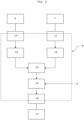
- Fig. 2 shows a flow chart of the operation of the control unit 8 of the inlet arrangement of the present invention.
- the force sensor 6 and the level sensor 7 transmit signals to the control unit 8.
- the signals are typically converted by A/D converters 10, 11 and further processed in processing units 12, 13.
- Said processing may comprise an operation selected from the group consisting of scaling, offset and filtering, and combinations thereof.
- the processed signals are transmitted to a calculation unit 14.
- a sensor value for the force sensor 6 is determined in dependence from the values detected by the level sensor 7.
- Said calculation may involve a calibration of the signals provided by the force sensor 6 on the basis of the signals provided by the level sensor 7.
- the thus obtained signal value is transmitted into a regulation unit 15, where the obtained signal value is compared with a setpoint level S that may be provided by an operator, for example via an input signal or a computer interface. If as a result of the comparison of the obtained signal value with the setpoint level a deviation of the two values is identified, the obtained signal value is adjusted to the setpoint value, as described above. Therewith, an output signal is generated that is transmitted, preferably via a D/A converter 16, to a machine control element 17. Said machine control element 17 may accordingly be caused to influence the flow of the material out of the storage container 2, for example by operating the metering device 5.
Landscapes
- Engineering & Computer Science (AREA)
- Food Science & Technology (AREA)
- Crushing And Grinding (AREA)
- Weight Measurement For Supplying Or Discharging Of Specified Amounts Of Material (AREA)
Claims (12)
- Einlassanordnung (1) für eine Mahlmaschine, vorzugsweise eine Walzenmühle, umfassend:- einen Vorratsbehälter (2) mit mindestens einem Mahlguteinlass (3) und mindestens einem Mahlgutauslass (4),- mindestens eine im Vorratsbehälter (2) angeordnete Dosiereinrichtung (5) zur Dosierung von Mahlgut durch den Mahlgutauslass (4) in einen Mahlspalt der Mahlmaschine, vorzugsweise Walzenmühle,- einen Hauptsensor, vorzugsweise einen Kraftsensor (6), der am Vorratsbehälter (2) auf einem Niveau zur Ermittlung einer vom Mahlgut ausgeübten Gewichtskraft (FG) vorgesehen ist,- einen zusätzlichen Sensor, vorzugsweise einen Füllstandssensor (7), der am Vorratsbehälter (2) vorgesehen ist, um einen Mahlgutfüllstand im Vorratsbehälter (2) zu ermitteln,- eine Steuereinheit (8), die mit dem Hauptsensor (6) und dem zusätzlichen Sensor (7) verbunden oder verbindbar ist,wobei die Steuereinheit (8) konfiguriert ist, aus den von dem Hauptsensor (6) und dem zusätzlichen Sensor (7) ermittelten Werten und einem Sollwert (S) ein Ausgangssignal zur Steuerung des Mahlgutflusses aus dem Vorratsbehälter (2) zu erzeugen, dadurch gekennzeichnet, dassder zusätzliche Sensor (7) in den Vorratsbehälter bis zu einem Niveau hineinragt, das dem Niveau entspricht, auf dem der Hauptsensor (6) angebracht ist.
- Einlassanordnung nach Anspruch 1, dadurch gekennzeichnet, dass die Steuereinheit (8) so konfiguriert ist, dass sie das Ausgangssignal auf der Grundlage eines Vergleichs eines Werts, der aus den von dem Hauptsensor (6) und dem zusätzlichen Sensor (7) stammenden Werten berechnet wird, mit dem Sollwert (S) erzeugt.
- Einlassanordnung nach Anspruch 1 oder 2, dadurch gekennzeichnet, dass der zusätzliche Sensor (7) ein Füllstandsensor, vorzugsweise ein kapazitiver Sensor, ist.
- Einlassanordnung nach einem der vorhergehenden Ansprüche, dadurch gekennzeichnet, dass als zusätzlicher Sensor (7) mehr als ein Sensor vorgesehen ist, vorzugsweise 2 bis 6, besonders bevorzugt 2 bis 4 Füllstandsensoren (7).
- Einlassanordnung nach einem der vorhergehenden Ansprüche, dadurch gekennzeichnet, dass der Hauptsensor (6) ein Kraftsensor ist, der einen in den Vorratsbehälter (2) hineinragenden Ausleger (9) umfasst, wobei der Ausleger (9) auf einem Niveau vorgesehen ist, die dem Niveau entspricht, auf dem sich ein Ende des zusätzlichen Sensors (7) im Vorratsbehälter (2) befindet.
- Einlassanordnung nach einem der vorhergehenden Ansprüche, dadurch gekennzeichnet, dass der Hauptsensor in einem unteren Bereich, vorzugsweise einem unteren Drittel, des Vorratsbehälters (2) angeordnet ist.
- Einlassanordnung nach einem der vorhergehenden Ansprüche, dadurch gekennzeichnet, dass die Einlassanordnung (1) ferner ein Maschinensteuerungselement (17) umfasst.
- Mahlmaschine, vorzugsweise Walzenmühle, umfassend mindestens zwei Walzen, die einen Spalt zwischen sich definieren, dadurch gekennzeichnet, dass die Mahlmaschine, vorzugsweise Walzenmühle, ferner eine Einlassanordnung (1) nach einem der Ansprüche 1 bis 7 umfasst.
- Verfahren zur Bestimmung und Steuerung des Mahlgutstandes in einem Vorratsbehälter (2) für Mahlgut einer Mahlmaschine, vorzugsweise einer Walzenmühle, wobei der Vorratsbehälter mindestens einen Mahlguteinlass (3), mindestens einen Mahlgutauslass (4) und mindestens eine Dosiereinrichtung (5) zur Dosierung von Mahlgut in einen Mahlspalt der Mahlmaschine, vorzugsweise Walzenmühle, durch den Mahlgutauslass (4) umfasst, wobei das Verfahren die folgenden Schritte umfasst:- Ermitteln einer ersten Kenngröße, vorzugsweise einer Gewichtskraft (FG), die von dem Mahlgut ausgeübt wird, mit einem am Vorratsbehälter (2) auf einem Niveau vorgesehenen Hauptsensor, vorzugsweise Kraftsensor (6),- Ermitteln eines Mahlgutstandes im Vorratsbehälter (2) mit einem zusätzlichen Sensor, vorzugsweise Füllstandssensor (7), der am Vorratsbehälter (2) so angebracht ist, dass der zusätzliche Sensor (7) in den Vorratsbehälter bis zu einem Niveau reicht, das dem Niveau entspricht, an dem der Hauptsensor (6) angebracht ist,- gegebenenfalls Verarbeitung der vom Hauptsensor (6) und vom zusätzlichen Sensor (7) erzeugten Signale,- Bereitstellung eines Sollwerts (S), vorzugsweise durch einen Bediener,- Erzeugung eines Ausgangssignal zur Steuerung des Mahlgutflusses aus dem Vorratsbehälter (2) aus den Werten des Hauptsensors (6) und des zusätzlichen Sensors (7) sowie dem Sollwert (S).
- Verfahren nach Anspruch 9, dadurch gekennzeichnet, dass das Ausgangssignal auf der Grundlage eines Vergleichs eines Werts, der aus den von dem Hauptsensor (6) und dem zusätzlichen Sensor (7) stammenden Werten berechnet wird, mit dem Sollwert (S) erzeugt wird.
- Verfahren nach Anspruch 9 oder 10, dadurch gekennzeichnet, dass der Vergleich des aus den vom Hauptsensor (6) und dem zusätzlichen Sensor (7) stammenden Werten berechneten Wertes mit dem Sollwert (S) einen Regelvorgang beinhaltet.
- Verfahren nach einem der Ansprüche 9 bis 11, dadurch gekennzeichnet, dass das Ausgangssignal an ein Maschinensteuerungselement (17) übertragen wird, das ein Element der Einlassanordnung (1) oder der Walzenmühle steuert.
Applications Claiming Priority (1)
| Application Number | Priority Date | Filing Date | Title |
|---|---|---|---|
| PCT/CN2021/105778 WO2023283766A1 (en) | 2021-07-12 | 2021-07-12 | Feed level control system and method |
Publications (2)
| Publication Number | Publication Date |
|---|---|
| EP4334037A1 EP4334037A1 (de) | 2024-03-13 |
| EP4334037B1 true EP4334037B1 (de) | 2025-03-12 |
Family
ID=77050731
Family Applications (1)
| Application Number | Title | Priority Date | Filing Date |
|---|---|---|---|
| EP21745890.0A Active EP4334037B1 (de) | 2021-07-12 | 2021-07-12 | Zufuhrniveausteuerungssystem und -verfahren |
Country Status (8)
| Country | Link |
|---|---|
| US (1) | US20240307886A1 (de) |
| EP (1) | EP4334037B1 (de) |
| JP (1) | JP7629547B2 (de) |
| KR (1) | KR20240025038A (de) |
| CN (1) | CN117561123A (de) |
| CA (1) | CA3221170A1 (de) |
| ES (1) | ES3031047T3 (de) |
| WO (1) | WO2023283766A1 (de) |
Family Cites Families (18)
| Publication number | Priority date | Publication date | Assignee | Title |
|---|---|---|---|---|
| IT1160480B (it) * | 1983-02-25 | 1987-03-11 | Sangati Spa | Dispositivo per la regolazione automatica della alimentazione del prodotto in un laminatoio di macinazione per cereali |
| IT1161106B (it) * | 1983-03-10 | 1987-03-11 | Sangati Spa | Dispositivo per la regolazione automatica della alimentazione del prodotto in un laminatoio di macinazione per cereali |
| FR2576223A1 (fr) * | 1985-01-24 | 1986-07-25 | Schneider Jaquet Cie Ets | Dispositif de reglage applicable a l'appareil de distribution quantitatif pour cylindres de broyage et de reduction |
| CH682809A5 (de) * | 1990-12-12 | 1993-11-30 | Buehler Ag | Produktspeiseautomatik, Verfahren zur Steuerung der Vermahlung eines Müllereiwalzenstuhles. |
| JP3266614B2 (ja) * | 1991-10-11 | 2002-03-18 | サタケ ユーケイ リミテッド | 穀物製粉機 |
| JP3127170B2 (ja) * | 1992-03-25 | 2001-01-22 | 日揮株式会社 | タンク内容物排出装置 |
| DE4425751A1 (de) * | 1994-07-21 | 1996-01-25 | Rolf Mannhaupt | Verfahren und Vorrichtung zur Bestimmung des Volumens von Schüttgütern sowie eine Verwendung des Verfahrens zur Bestimmung des Schüttgewichtes von Formsand |
| JP4599492B2 (ja) * | 2003-12-09 | 2010-12-15 | 明治機械株式会社 | 穀物・種子・固形樹脂の製粉機 |
| CN200989806Y (zh) * | 2006-11-06 | 2007-12-12 | 河南中原轧辊有限公司 | 磨粉机喂料传感装置 |
| JP5108855B2 (ja) * | 2009-10-23 | 2012-12-26 | 明治機械株式会社 | 穀物・種子・固形樹脂の製粉機 |
| WO2013115747A1 (en) * | 2012-02-03 | 2013-08-08 | Yukselis Makina Sanayi Ve Ticaret Anonim Sirketi | Easy mounted level detection mechanism |
| JP6238044B2 (ja) * | 2013-04-23 | 2017-11-29 | 株式会社サタケ | 製粉用ロール機におけるストックレベル検出器 |
| KR20160001461A (ko) * | 2014-06-27 | 2016-01-06 | 농업회사법인 주식회사 오색미면 | 곡물수분함량 측정장치 |
| CN207209417U (zh) * | 2017-09-03 | 2018-04-10 | 南阳飞鹏节能技术服务有限公司 | 一种锁风卸料装置 |
| ES2824761T3 (es) * | 2018-05-25 | 2021-05-13 | Buehler Ag | Dispositivo de distribución-dosificación para un molino de cilindros, molino de cilindros con un dispositivo de distribución-dosificación de este tipo y procedimiento para moler material a moler |
| ES2901827T3 (es) * | 2018-07-31 | 2022-03-23 | Buehler Ag | Dispositivo de entrada para un molino de cilindros, molino de cilindros con un dispositivo de entrada de este tipo, procedimiento para la determinación del nivel de relleno de material de molienda de un depósito de almacenamiento de un molino de cilindros |
| CN110354980B (zh) * | 2019-08-20 | 2024-07-02 | 中粮工程装备(张家口)有限公司 | 一种磨粉机用喂料高度测量系统 |
| CN212732525U (zh) * | 2020-06-11 | 2021-03-19 | 威立雅新能源科技(江门)有限公司 | 一种电池破碎机的给料装置 |
-
2021
- 2021-07-12 CN CN202180099879.8A patent/CN117561123A/zh active Pending
- 2021-07-12 CA CA3221170A patent/CA3221170A1/en active Pending
- 2021-07-12 JP JP2023579203A patent/JP7629547B2/ja active Active
- 2021-07-12 EP EP21745890.0A patent/EP4334037B1/de active Active
- 2021-07-12 WO PCT/CN2021/105778 patent/WO2023283766A1/en not_active Ceased
- 2021-07-12 US US18/577,101 patent/US20240307886A1/en active Pending
- 2021-07-12 KR KR1020247004315A patent/KR20240025038A/ko active Pending
- 2021-07-12 ES ES21745890T patent/ES3031047T3/es active Active
Also Published As
| Publication number | Publication date |
|---|---|
| CN117561123A (zh) | 2024-02-13 |
| US20240307886A1 (en) | 2024-09-19 |
| EP4334037A1 (de) | 2024-03-13 |
| JP7629547B2 (ja) | 2025-02-13 |
| ES3031047T3 (en) | 2025-07-03 |
| CA3221170A1 (en) | 2023-01-19 |
| WO2023283766A1 (en) | 2023-01-19 |
| JP2024523920A (ja) | 2024-07-02 |
| KR20240025038A (ko) | 2024-02-26 |
Similar Documents
| Publication | Publication Date | Title |
|---|---|---|
| CA1099689A (en) | Weigh feeding apparatus | |
| CN102389742B (zh) | 一种高精度配料设备及其控制方法 | |
| USRE32101E (en) | Weigh feeding apparatus | |
| CN1128021C (zh) | 辊式碾磨机的给料传感器装置和辊式碾磨机的控制方法 | |
| CN112585438B (zh) | 辊磨机的导入装置、辊磨机及确定碾磨物料料位的方法 | |
| WO2018213869A1 (en) | Train load-out arrangement | |
| CN114104770A (zh) | 一种控制粉体供料器供料速率的方法及系统 | |
| US6863913B1 (en) | Food preparation process using bulk density feedback | |
| EP4334037B1 (de) | Zufuhrniveausteuerungssystem und -verfahren | |
| CN119858774A (zh) | 一种用于粉体装钵的输送装置及其计量称重系统 | |
| JP2011185691A (ja) | 粉粒体の供給量制御方法および粉粒体供給装置 | |
| US20240262637A1 (en) | Continuously Flowing Seed Metering and Discharge System | |
| US12178216B2 (en) | Filling and portioning system for food products and method for rotational speed control of an associated feeder/mixing arm and/or counterholding device | |
| CN105836421B (zh) | 一种多级固体输送设备联动控制方法 | |
| JP2661838B2 (ja) | スクリューフィーダ式定量切り出し装置 | |
| EP3242113A1 (de) | System und verfahren zum dosieren von pulver oder korn in einem chargenverfahren | |
| JP2000141445A (ja) | 押出成形機に対する原料供給量の制御方法および制御装置 | |
| US7154055B2 (en) | Method and apparatus for dividing portions | |
| CN217511918U (zh) | 一种碾米机精度控制系统 | |
| JP2009274799A (ja) | 粉体切出し装置の制御方法 | |
| KR20000014370U (ko) | 원료 불출량 검출장치 | |
| CN102625925A (zh) | 用于重量损失成分添加的装置和方法 | |
| CN218659853U (zh) | 一种用于稳定土厂拌设备在线标定的粉料计量系统 | |
| JP2022142232A (ja) | 貯留物の供給量制御方法およびシステム | |
| JPS641729B2 (de) |
Legal Events
| Date | Code | Title | Description |
|---|---|---|---|
| STAA | Information on the status of an ep patent application or granted ep patent |
Free format text: STATUS: UNKNOWN |
|
| STAA | Information on the status of an ep patent application or granted ep patent |
Free format text: STATUS: THE INTERNATIONAL PUBLICATION HAS BEEN MADE |
|
| PUAI | Public reference made under article 153(3) epc to a published international application that has entered the european phase |
Free format text: ORIGINAL CODE: 0009012 |
|
| STAA | Information on the status of an ep patent application or granted ep patent |
Free format text: STATUS: REQUEST FOR EXAMINATION WAS MADE |
|
| STAA | Information on the status of an ep patent application or granted ep patent |
Free format text: STATUS: EXAMINATION IS IN PROGRESS |
|
| 17P | Request for examination filed |
Effective date: 20231205 |
|
| AK | Designated contracting states |
Kind code of ref document: A1 Designated state(s): AL AT BE BG CH CY CZ DE DK EE ES FI FR GB GR HR HU IE IS IT LI LT LU LV MC MK MT NL NO PL PT RO RS SE SI SK SM TR |
|
| 17Q | First examination report despatched |
Effective date: 20240305 |
|
| DAV | Request for validation of the european patent (deleted) | ||
| DAX | Request for extension of the european patent (deleted) | ||
| GRAP | Despatch of communication of intention to grant a patent |
Free format text: ORIGINAL CODE: EPIDOSNIGR1 |
|
| STAA | Information on the status of an ep patent application or granted ep patent |
Free format text: STATUS: GRANT OF PATENT IS INTENDED |
|
| INTG | Intention to grant announced |
Effective date: 20250102 |
|
| GRAS | Grant fee paid |
Free format text: ORIGINAL CODE: EPIDOSNIGR3 |
|
| GRAA | (expected) grant |
Free format text: ORIGINAL CODE: 0009210 |
|
| STAA | Information on the status of an ep patent application or granted ep patent |
Free format text: STATUS: THE PATENT HAS BEEN GRANTED |
|
| AK | Designated contracting states |
Kind code of ref document: B1 Designated state(s): AL AT BE BG CH CY CZ DE DK EE ES FI FR GB GR HR HU IE IS IT LI LT LU LV MC MK MT NL NO PL PT RO RS SE SI SK SM TR |
|
| REG | Reference to a national code |
Ref country code: GB Ref legal event code: FG4D |
|
| REG | Reference to a national code |
Ref country code: CH Ref legal event code: EP |
|
| REG | Reference to a national code |
Ref country code: DE Ref legal event code: R096 Ref document number: 602021027535 Country of ref document: DE |
|
| P01 | Opt-out of the competence of the unified patent court (upc) registered |
Free format text: CASE NUMBER: APP_9405/2025 Effective date: 20250225 |
|
| REG | Reference to a national code |
Ref country code: IE Ref legal event code: FG4D |
|
| REG | Reference to a national code |
Ref country code: ES Ref legal event code: FG2A Ref document number: 3031047 Country of ref document: ES Kind code of ref document: T3 Effective date: 20250703 |
|
| PG25 | Lapsed in a contracting state [announced via postgrant information from national office to epo] |
Ref country code: RS Free format text: LAPSE BECAUSE OF FAILURE TO SUBMIT A TRANSLATION OF THE DESCRIPTION OR TO PAY THE FEE WITHIN THE PRESCRIBED TIME-LIMIT Effective date: 20250612 |
|
| PG25 | Lapsed in a contracting state [announced via postgrant information from national office to epo] |
Ref country code: FI Free format text: LAPSE BECAUSE OF FAILURE TO SUBMIT A TRANSLATION OF THE DESCRIPTION OR TO PAY THE FEE WITHIN THE PRESCRIBED TIME-LIMIT Effective date: 20250312 |
|
| REG | Reference to a national code |
Ref country code: LT Ref legal event code: MG9D |
|
| PG25 | Lapsed in a contracting state [announced via postgrant information from national office to epo] |
Ref country code: NO Free format text: LAPSE BECAUSE OF FAILURE TO SUBMIT A TRANSLATION OF THE DESCRIPTION OR TO PAY THE FEE WITHIN THE PRESCRIBED TIME-LIMIT Effective date: 20250612 |
|
| PG25 | Lapsed in a contracting state [announced via postgrant information from national office to epo] |
Ref country code: HR Free format text: LAPSE BECAUSE OF FAILURE TO SUBMIT A TRANSLATION OF THE DESCRIPTION OR TO PAY THE FEE WITHIN THE PRESCRIBED TIME-LIMIT Effective date: 20250312 |
|
| REG | Reference to a national code |
Ref country code: NL Ref legal event code: MP Effective date: 20250312 |
|
| PG25 | Lapsed in a contracting state [announced via postgrant information from national office to epo] |
Ref country code: LV Free format text: LAPSE BECAUSE OF FAILURE TO SUBMIT A TRANSLATION OF THE DESCRIPTION OR TO PAY THE FEE WITHIN THE PRESCRIBED TIME-LIMIT Effective date: 20250312 |
|
| PG25 | Lapsed in a contracting state [announced via postgrant information from national office to epo] |
Ref country code: BG Free format text: LAPSE BECAUSE OF FAILURE TO SUBMIT A TRANSLATION OF THE DESCRIPTION OR TO PAY THE FEE WITHIN THE PRESCRIBED TIME-LIMIT Effective date: 20250312 Ref country code: GR Free format text: LAPSE BECAUSE OF FAILURE TO SUBMIT A TRANSLATION OF THE DESCRIPTION OR TO PAY THE FEE WITHIN THE PRESCRIBED TIME-LIMIT Effective date: 20250613 |
|
| PG25 | Lapsed in a contracting state [announced via postgrant information from national office to epo] |
Ref country code: NL Free format text: LAPSE BECAUSE OF FAILURE TO SUBMIT A TRANSLATION OF THE DESCRIPTION OR TO PAY THE FEE WITHIN THE PRESCRIBED TIME-LIMIT Effective date: 20250312 |
|
| PG25 | Lapsed in a contracting state [announced via postgrant information from national office to epo] |
Ref country code: SE Free format text: LAPSE BECAUSE OF FAILURE TO SUBMIT A TRANSLATION OF THE DESCRIPTION OR TO PAY THE FEE WITHIN THE PRESCRIBED TIME-LIMIT Effective date: 20250312 |
|
| PG25 | Lapsed in a contracting state [announced via postgrant information from national office to epo] |
Ref country code: SM Free format text: LAPSE BECAUSE OF FAILURE TO SUBMIT A TRANSLATION OF THE DESCRIPTION OR TO PAY THE FEE WITHIN THE PRESCRIBED TIME-LIMIT Effective date: 20250312 |
|
| PG25 | Lapsed in a contracting state [announced via postgrant information from national office to epo] |
Ref country code: PT Free format text: LAPSE BECAUSE OF FAILURE TO SUBMIT A TRANSLATION OF THE DESCRIPTION OR TO PAY THE FEE WITHIN THE PRESCRIBED TIME-LIMIT Effective date: 20250714 |
|
| PGFP | Annual fee paid to national office [announced via postgrant information from national office to epo] |
Ref country code: ES Payment date: 20250819 Year of fee payment: 5 |
|
| PGFP | Annual fee paid to national office [announced via postgrant information from national office to epo] |
Ref country code: DE Payment date: 20250722 Year of fee payment: 5 |
|
| PG25 | Lapsed in a contracting state [announced via postgrant information from national office to epo] |
Ref country code: PL Free format text: LAPSE BECAUSE OF FAILURE TO SUBMIT A TRANSLATION OF THE DESCRIPTION OR TO PAY THE FEE WITHIN THE PRESCRIBED TIME-LIMIT Effective date: 20250312 |
|
| PGFP | Annual fee paid to national office [announced via postgrant information from national office to epo] |
Ref country code: IT Payment date: 20250731 Year of fee payment: 5 Ref country code: TR Payment date: 20250707 Year of fee payment: 5 |
|
| PGFP | Annual fee paid to national office [announced via postgrant information from national office to epo] |
Ref country code: GB Payment date: 20250724 Year of fee payment: 5 |
|
| PGFP | Annual fee paid to national office [announced via postgrant information from national office to epo] |
Ref country code: FR Payment date: 20250723 Year of fee payment: 5 Ref country code: AT Payment date: 20251020 Year of fee payment: 5 |
|
| PGFP | Annual fee paid to national office [announced via postgrant information from national office to epo] |
Ref country code: CH Payment date: 20250724 Year of fee payment: 5 |
|
| PG25 | Lapsed in a contracting state [announced via postgrant information from national office to epo] |
Ref country code: EE Free format text: LAPSE BECAUSE OF FAILURE TO SUBMIT A TRANSLATION OF THE DESCRIPTION OR TO PAY THE FEE WITHIN THE PRESCRIBED TIME-LIMIT Effective date: 20250312 Ref country code: CZ Free format text: LAPSE BECAUSE OF FAILURE TO SUBMIT A TRANSLATION OF THE DESCRIPTION OR TO PAY THE FEE WITHIN THE PRESCRIBED TIME-LIMIT Effective date: 20250312 |
|
| PG25 | Lapsed in a contracting state [announced via postgrant information from national office to epo] |
Ref country code: RO Free format text: LAPSE BECAUSE OF FAILURE TO SUBMIT A TRANSLATION OF THE DESCRIPTION OR TO PAY THE FEE WITHIN THE PRESCRIBED TIME-LIMIT Effective date: 20250312 |
|
| PG25 | Lapsed in a contracting state [announced via postgrant information from national office to epo] |
Ref country code: SK Free format text: LAPSE BECAUSE OF FAILURE TO SUBMIT A TRANSLATION OF THE DESCRIPTION OR TO PAY THE FEE WITHIN THE PRESCRIBED TIME-LIMIT Effective date: 20250312 |
|
| PG25 | Lapsed in a contracting state [announced via postgrant information from national office to epo] |
Ref country code: IS Free format text: LAPSE BECAUSE OF FAILURE TO SUBMIT A TRANSLATION OF THE DESCRIPTION OR TO PAY THE FEE WITHIN THE PRESCRIBED TIME-LIMIT Effective date: 20250712 |
|
| REG | Reference to a national code |
Ref country code: DE Ref legal event code: R097 Ref document number: 602021027535 Country of ref document: DE |
|
| PG25 | Lapsed in a contracting state [announced via postgrant information from national office to epo] |
Ref country code: DK Free format text: LAPSE BECAUSE OF FAILURE TO SUBMIT A TRANSLATION OF THE DESCRIPTION OR TO PAY THE FEE WITHIN THE PRESCRIBED TIME-LIMIT Effective date: 20250312 |
|
| PLBE | No opposition filed within time limit |
Free format text: ORIGINAL CODE: 0009261 |
|
| STAA | Information on the status of an ep patent application or granted ep patent |
Free format text: STATUS: NO OPPOSITION FILED WITHIN TIME LIMIT |
|
| REG | Reference to a national code |
Ref country code: CH Ref legal event code: L10 Free format text: ST27 STATUS EVENT CODE: U-0-0-L10-L00 (AS PROVIDED BY THE NATIONAL OFFICE) Effective date: 20260121 |
|
| 26N | No opposition filed |
Effective date: 20251215 |
|
| PG25 | Lapsed in a contracting state [announced via postgrant information from national office to epo] |
Ref country code: LU Free format text: LAPSE BECAUSE OF NON-PAYMENT OF DUE FEES Effective date: 20250712 |
|
| REG | Reference to a national code |
Ref country code: BE Ref legal event code: MM Effective date: 20250731 |
|
| PG25 | Lapsed in a contracting state [announced via postgrant information from national office to epo] |
Ref country code: BE Free format text: LAPSE BECAUSE OF NON-PAYMENT OF DUE FEES Effective date: 20250731 |