EP4334085B1 - Appareil de projection de matière particulaire et procédé de sablage d'une surface - Google Patents
Appareil de projection de matière particulaire et procédé de sablage d'une surface Download PDFInfo
- Publication number
- EP4334085B1 EP4334085B1 EP22728134.2A EP22728134A EP4334085B1 EP 4334085 B1 EP4334085 B1 EP 4334085B1 EP 22728134 A EP22728134 A EP 22728134A EP 4334085 B1 EP4334085 B1 EP 4334085B1
- Authority
- EP
- European Patent Office
- Prior art keywords
- particulate material
- rotor
- delivery conduit
- storage tank
- blasting apparatus
- Prior art date
- Legal status (The legal status is an assumption and is not a legal conclusion. Google has not performed a legal analysis and makes no representation as to the accuracy of the status listed.)
- Active
Links
Images

Classifications
-
- B—PERFORMING OPERATIONS; TRANSPORTING
- B24—GRINDING; POLISHING
- B24C—ABRASIVE OR RELATED BLASTING WITH PARTICULATE MATERIAL
- B24C7/00—Equipment for feeding abrasive material; Controlling the flowability, constitution, or other physical characteristics of abrasive blasts
- B24C7/0092—Equipment for feeding abrasive material; Controlling the flowability, constitution, or other physical characteristics of abrasive blasts the abrasive material being fed by mechanical means, e.g. by screw conveyors
-
- B—PERFORMING OPERATIONS; TRANSPORTING
- B24—GRINDING; POLISHING
- B24C—ABRASIVE OR RELATED BLASTING WITH PARTICULATE MATERIAL
- B24C7/00—Equipment for feeding abrasive material; Controlling the flowability, constitution, or other physical characteristics of abrasive blasts
- B24C7/0046—Equipment for feeding abrasive material; Controlling the flowability, constitution, or other physical characteristics of abrasive blasts the abrasive material being fed in a gaseous carrier
- B24C7/0076—Equipment for feeding abrasive material; Controlling the flowability, constitution, or other physical characteristics of abrasive blasts the abrasive material being fed in a gaseous carrier the blasting medium being a liquid stream
-
- B—PERFORMING OPERATIONS; TRANSPORTING
- B05—SPRAYING OR ATOMISING IN GENERAL; APPLYING FLUENT MATERIALS TO SURFACES, IN GENERAL
- B05B—SPRAYING APPARATUS; ATOMISING APPARATUS; NOZZLES
- B05B7/00—Spraying apparatus for discharge of liquids or other fluent materials from two or more sources, e.g. of liquid and air, of powder and gas
- B05B7/14—Spraying apparatus for discharge of liquids or other fluent materials from two or more sources, e.g. of liquid and air, of powder and gas designed for spraying particulate materials
- B05B7/1404—Arrangements for supplying particulate material
-
- B—PERFORMING OPERATIONS; TRANSPORTING
- B05—SPRAYING OR ATOMISING IN GENERAL; APPLYING FLUENT MATERIALS TO SURFACES, IN GENERAL
- B05B—SPRAYING APPARATUS; ATOMISING APPARATUS; NOZZLES
- B05B7/00—Spraying apparatus for discharge of liquids or other fluent materials from two or more sources, e.g. of liquid and air, of powder and gas
- B05B7/14—Spraying apparatus for discharge of liquids or other fluent materials from two or more sources, e.g. of liquid and air, of powder and gas designed for spraying particulate materials
- B05B7/1404—Arrangements for supplying particulate material
- B05B7/144—Arrangements for supplying particulate material the means for supplying particulate material comprising moving mechanical means
-
- B—PERFORMING OPERATIONS; TRANSPORTING
- B65—CONVEYING; PACKING; STORING; HANDLING THIN OR FILAMENTARY MATERIAL
- B65G—TRANSPORT OR STORAGE DEVICES, e.g. CONVEYORS FOR LOADING OR TIPPING, SHOP CONVEYOR SYSTEMS OR PNEUMATIC TUBE CONVEYORS
- B65G65/00—Loading or unloading
- B65G65/30—Methods or devices for filling or emptying bunkers, hoppers, tanks, or like containers, of interest apart from their use in particular chemical or physical processes or their application in particular machines, e.g. not covered by a single other subclass
- B65G65/34—Emptying devices
- B65G65/40—Devices for emptying otherwise than from the top
- B65G65/48—Devices for emptying otherwise than from the top using other rotating means, e.g. rotating pressure sluices in pneumatic systems
- B65G65/4881—Devices for emptying otherwise than from the top using other rotating means, e.g. rotating pressure sluices in pneumatic systems rotating about a substantially horizontal axis
Definitions
- the present invention relates to a particulate material blasting apparatus according to the preamble of claim 1. Also contemplated is a method of blasting a surface with particulate material.
- Dosing devices for non-abrasive blasting are known and generally comprise a product feed conduit, a dosing chamber for metering the blasting media, and a pressurised fluid line into which the metered media is dosed.
- the mixture of metered media and fluid are fed under pressure to a dispensing nozzle.
- Conventional dosing systems use a pressure differential to meter the amount of media charged into the fluid.
- a dosing device comprising a spinning disk with a hole, wherein media is dosed when the hole rotates into register with media feed and supply conduits.
- An example of such a device is described in US Patent Serial No. 6,896,197 .
- a seal is required between spinning disk and the plates between the disk is mounted to prevent seepage of media when the disk is not operational.
- the seal is rapidly destroyed due to the friction between the disks and the plates; this problem is exacerbated by the media which has an abrasive effect on the disks and plates, resulting in the device only being usable with non-abrasive material.
- United States Patent No: 3,758,004 describes a dosing device for particulate material having a dosing chamber within which is mounted a rotatable rotor for delivery of particulate material into a dispensing outlet.
- the device is designed with very close tolerances between the periphery of the rotor and the walls of the dosing chamber to avoid passage of particulate material into the dispending outlet when the rotor is not turning. Such close tolerances cause friction and wear on the adjacent surfaces of the rotor and the dispensing chamber, which problems are exacerbated by any media which falls into tight gaps between the surfaces.
- EP0652078 describes a device for feeding particles into a flow of air.
- the device illustrated in Figures 27 to 29 comprises a hopper, a particulate material discharge area disposed on one side of a base of the hopper, and an inlet of a nozzle disposed in the discharge area which draws the particulate material into the flow of air in the nozzle.
- the discharge area and hopper are separated by a rotary valve which rotates counter-clockwise ( Figure 27) to pull material down and around and into the discharge area.
- the rotary valve acts as a stop to prevent material flowing into the discharge area, and this requires very close tolerances between the rotary valve and the housing which are prone to being clogged with particulate material.
- JP H0994765 describes a dosing device for particulate material having a hopper 12 to store material and a dosing device 2 that is separate to the hopper and connected thereto by a conveying tube 15.
- the dosing device comprises a rotating wheel with pockets that lift up particulate material to an outlet tube disposed above the wheel which suck particulate material up into the outlet tube.
- the device is bulky and has separate parts which complicates manufacture.
- a pressure equalisation conduit (23 in Figures 1 and 2 ) is required to balance pressure between the pressurised storage tank and the dosing device.
- WO2007/107322 describes a dosing device for particulate material and blasting apparatus.
- the dosing device has a dosing chamber with a material receiving side, a material dispensing side, and a rotor interposed between the dispensing and receiving sides.
- Material is delivered onto a base of the material receiving side by a feed conduit from the pressurised storage tank, and rotation of the rotor lifts the material up (typically in a scooping action) from the receiving side and delivers it to the delivery side of the dosing chamber.
- the base of the material receiving side is disposed with respect of the feed conduit such that particulate material will not spill into the delivery side of the dosing chamber when the rotor is static.
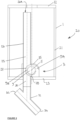
- the invention provides a particulate material blasting apparatus comprising a particulate material dosing device, a particulate material storage tank adapted to feed particulate material to the dosing device, and a delivery conduit to deliver particular material into a pressurised gas line.
- the delivery conduit has an upper part comprising a first inlet aperture disposed in the particulate material storage tank and a lower part comprising an outlet disposed outside the particulate material storage tank.
- the delivery conduit is generally disposed vertically (or nearly vertically) with respect to the base of the storage tank so that particulate material falls from the inlet to the outlet easily and under the force of gravity.
- the tank generally has a base, top and sidewalls.
- the dosing device comprises a rotor comprising a series of scooping pockets mounted along a circumference of the rotor configured to rotate to scoop-up particular material from a particulate material receiving side of the rotor and deliver it up and around to a delivery side of the rotor where it falls into the delivery conduit through the inlet and falls downwardly into a pressurised gas line.
- the dosing device is located in the particulate material storage tank and the delivery conduit comprises an outlet disposed outside the particulate material storage tank.
- the upper part (of the delivery conduit) comprises an elongated pipe and the first inlet aperture of the delivery conduit is disposed adjacent the base of the particulate material storage tank, wherein the rotor is mounted partly within the first inlet aperture such that a particulate material receiving side of the rotor is disposed outside the pipe and a particulate material receiving side of the rotor is disposed inside the pipe.
- the delivery conduit comprises a second inlet aperture disposed toward a top of the particulate material storage tank. This inlet allows the delivery conduit to also function as a pressure equalisation conduit and normalise pressure between the top and bottom of the pressurised tank.
- the dosing device may comprise a baffle attached to the delivery conduit dimensioned to curve around and cover a top (and preferably the sides) of the particulate material receiving side of the rotor. This serves to guide particulate material away from the top of the rotor and towards the material receiving side of the rotor, preventing the rotor becoming clogged with material.
- the apparatus may comprise a bearing, gearbox and a motor for the rotor.
- the bearing, gearbox and optionally the motor may be contained within a sealed housing coupled to the base of the particulate material storage tank.
- the dosing device may comprise a plurality of rotors, in which the scooping pockets of one rotor are typically circumferentially staggered with respect to those of the other rotor.
- the rotor has the same construction as that illustrated in WO2007/107322 with three axially aligned rotors each having a series of scooping pockets configured to pick up material from a media receiving side of the dosing device and deliver media up and around to a material delivery side of the dosing device where it falls into the delivery conduit.
- a particulate material such as particles of agglomerated calcium carbonate is added to the tank and comes to rest on the bottom wall of the tank at the media receiving side of the dosing device.
- the lip and curved baffle serve to prevent media falling into the delivery conduit until the rotor is actuated.
- the rotor Due to the disposition of the rotor with respect to the conduit and the bottom wall of the tank, rotation of the rotor results in media being scooped up and lifted upwards in the circumferential pockets and delivered from a product receiving side of the dosing device to a product delivery side where the product falls into the product delivery conduit and is delivered into the pressurised air supply line.
- the air pressure in the air supply line may be varied, and the amount of particulate product metered into the outlet may be varied by varying the speed of the rotor.
- the apparatus of the invention allows the costs of manufacture and assembly to be reduced by simplifying the whole assembly.
- the dosing unit and the media are put into the same, evenly pressured enclosure allowing the walls and components to be thin and cheap, even made from soft plastic, because they will not endure high pressure gradients between inner and outer surfaces.
- the dosing unit and the tank are separated and connected through two pipes, one that allows the media to flow in the dosing unit and the other that allows balancing of the pressures between the dosing device and tank.
- one conduit performs both roles.
- the pressure will be the same everywhere and the balancing of pressures is eased.
Landscapes
- Engineering & Computer Science (AREA)
- Mechanical Engineering (AREA)
- Filling Or Emptying Of Bunkers, Hoppers, And Tanks (AREA)
- Basic Packing Technique (AREA)
Claims (13)
- Appareil de projection de matière particulaire (20) comprenant :un dispositif de dosage de matière particulaire (3) ;une cuve de stockage de matière particulaire (1) présentant une base (23), une partie supérieure (22) et des parois latérales (21) et conçue pour alimenter le dispositif de dosage en matière particulaire ; etune conduite de distribution (25) pour délivrer la matière particulaire dans une conduite de gaz sous pression,le dispositif de dosage de matière particulaire comprenant un rotor (9) comprenant une série de poches de ramassage montées le long d'une circonférence du rotor configurée pour tourner afin de ramasser la matière particulaire à partir d'un côté récepteur de matière particulaire du dispositif de dosage et la délivrer vers le haut et de l'autre côté à un côté de distribution du dispositif de dosage où elle tombe dans la conduite de distribution (25),le dispositif de dosage de matière particulaire (3) étant situé dans la cuve de stockage de matière particulaire et la conduite de distribution comprenant une partie supérieure, disposée à l'intérieur de la cuve de stockage de matière particulaire (1), présentant une première ouverture d'entrée (27) et une partie inférieure, disposée à l'extérieur de la cuve de stockage de matière particulaire (1), présentant une sortie (30) pour distribuer la matière particulaire dans une conduite de gaz sous pression,caractérisé en ce que la partie supérieure comprend un tuyau allongé (26), en ce que la première ouverture d'entrée (27) est disposée adjacente à la base (23) de la cuve de stockage de matière particulaire, dans lequel le rotor (9) est monté en partie à l'intérieur de la première ouverture d'entrée de telle sorte qu'un côté récepteur de matière particulaire (9A) du rotor soit disposé à l'extérieur du tuyau (26) et un côté distributeur de matière particulaire (9B) du rotor est disposée à l'intérieur du tuyau (26) et en ce que la partie supérieure de la conduite de distribution (25) comprend une seconde ouverture d'entrée (26A) disposée vers une partie haute de la cuve de stockage de matière particulaire.
- Appareil de projection de matière particulaire selon la revendication 1, comprenant un déflecteur (35) fixé à la conduite de distribution (25) dimensionné pour s'incurver autour et couvrir un sommet et des côtés du côté récepteur de matière particulaire (9A) du rotor.
- Appareil de projection de matière particulaire selon l'une quelconque des revendications précédentes, comprenant un palier, une boîte de vitesses et éventuellement un moteur pour le rotor, dans lequel le palier, la boîte de vitesses et éventuellement le moteur sont contenus dans un boîtier étanche couplé à la base (23) de la cuve de stockage de matière particulaire (1).
- Appareil de projection de matière particulaire selon l'une quelconque des revendications précédentes, dans lequel la sortie (30) est configurée pour être couplée fluidiquement à une conduite de gaz sous pression.
- Appareil de projection de matière particulaire selon l'une quelconque des revendications précédentes, dans lequel la partie haute (22) de la cuve de stockage de matière particulaire comprend un raccord destiné à recevoir une partie haute de la conduite de distribution (25) et à fixer la conduite de distribution en position à l'intérieur de la cuve de stockage de matière particulaire (1).
- Appareil de projection de matière particulaire selon l'une quelconque des revendications précédentes, dans lequel un jeu entre le rotor (9) et la base (23) de la cuve de stockage de matière particulaire (1) est d'environ 0,2 cm à environ 0,6 cm.
- Appareil de projection de matière particulaire selon l'une quelconque des revendications précédentes, dans lequel le rotor (9) est monté dans l'ouverture (27) de la conduite de distribution (25) de telle sorte qu'un axe (11) du rotor soit perpendiculaire à un axe longitudinal de la conduite de distribution.
- Appareil de projection de matière particulaire selon l'une quelconque des revendications précédentes, dans lequel le rotor (9) est monté dans l'ouverture (27) de la conduite de distribution de telle sorte qu'un axe (11) du rotor soit aligné avec une paroi latérale de la conduite de distribution.
- Appareil de projection de matière particulaire selon l'une quelconque des revendications précédentes, dans lequel la conduite de distribution (25) et la cuve de stockage de matière particulaire (1) comprennent un tuyau cylindrique.
- Appareil de projection de matière particulaire selon l'une quelconque des revendications précédentes et comprenant au moins deux séries de poches de ramassage montées le long de la circonférence du rotor (9), et dans lequel les poches d'une série sont circonférentiellement décalées par rapport aux poches de l'autre série.
- Appareil de projection de matière particulaire selon l'une quelconque des revendications précédentes et comprenant une pluralité de rotors, dans lequel les poches de ramassage d'un rotor sont circonférentiellement décalées par rapport à celles du ou des autres rotors.
- Appareil de projection de matière particulaire selon l'une quelconque des revendications précédentes, dans lequel les poches sont formées par des formations en forme de dents qui dépassent de la circonférence du rotor.
- Procédé de sablage d'une surface avec une matière particulaire qui utilise un appareil de projection de matière particulaire (2) selon l'une quelconque des revendications 1 à 12, lequel procédé comprend les étapes de :fourniture d'un réservoir de matière particulaire dans la cuve de stockage de matière particulaire ;actionnement d'un moteur pour faire tourner le rotor à une vitesse souhaitée correspondant au taux de dosage de matière souhaité, et dosage de la matière particulaire à travers la conduite de distribution dans une conduite de gaz sous pression disposée à l'extérieur du réservoir de stockage ; etsablage d'une surface à l'aide d'une buse couplée fluidiquement à la conduite de gaz sous pression pour diriger un flux de gaz sous pression et de matière particulaire vers la surface.
Applications Claiming Priority (2)
| Application Number | Priority Date | Filing Date | Title |
|---|---|---|---|
| GBGB2106398.7A GB202106398D0 (en) | 2021-05-05 | 2021-05-05 | A particulate material blasting apparatus |
| PCT/EP2022/062228 WO2022234055A1 (fr) | 2021-05-05 | 2022-05-05 | Appareil de projection de matière particulaire et procédé de sablage d'une surface |
Publications (3)
| Publication Number | Publication Date |
|---|---|
| EP4334085A1 EP4334085A1 (fr) | 2024-03-13 |
| EP4334085B1 true EP4334085B1 (fr) | 2025-07-09 |
| EP4334085C0 EP4334085C0 (fr) | 2025-07-09 |
Family
ID=76301111
Family Applications (1)
| Application Number | Title | Priority Date | Filing Date |
|---|---|---|---|
| EP22728134.2A Active EP4334085B1 (fr) | 2021-05-05 | 2022-05-05 | Appareil de projection de matière particulaire et procédé de sablage d'une surface |
Country Status (5)
| Country | Link |
|---|---|
| US (1) | US20240227125A1 (fr) |
| EP (1) | EP4334085B1 (fr) |
| CN (1) | CN117480032A (fr) |
| GB (1) | GB202106398D0 (fr) |
| WO (1) | WO2022234055A1 (fr) |
Family Cites Families (19)
| Publication number | Priority date | Publication date | Assignee | Title |
|---|---|---|---|---|
| US2092201A (en) * | 1936-05-25 | 1937-09-07 | W W Sly Mfg Company | Abrasion method and apparatus |
| US2684788A (en) * | 1950-02-09 | 1954-07-27 | Flex O Lite Mfg Corp | Bead dispenser |
| GB832246A (en) * | 1956-12-17 | 1960-04-06 | Ici Ltd | Process and apparatus for discharging solid particles |
| US2907444A (en) * | 1956-12-17 | 1959-10-06 | Ici Ltd | Rotary apparatus for conveying solid particles |
| US3758004A (en) | 1972-02-28 | 1973-09-11 | L Garrett | Dial-controlled dispenser for powdered or particular material |
| IT7921448A0 (it) * | 1979-03-30 | 1979-03-30 | Assoni Pietro Assoni Luciano | Macchina sabbiatrice. |
| US4267946A (en) * | 1979-10-01 | 1981-05-19 | Thatcher Gary G | Particulate matter dispensing device |
| JP2772464B2 (ja) | 1993-10-22 | 1998-07-02 | 昭和炭酸株式会社 | 粉粒体の供給装置 |
| DE29503610U1 (de) * | 1995-03-03 | 1995-07-20 | Tal-Lufttechnik GmbH, 78224 Singen | Vorrichtung zum Schneiden von Werkstücken |
| JPH0994765A (ja) | 1995-09-29 | 1997-04-08 | Saitou Ika Kogyo Kk | ブラスト加工機 |
| GB9924095D0 (en) | 1999-10-13 | 1999-12-15 | Exa Sa | Abrasive blasting |
| US7112120B2 (en) * | 2002-04-17 | 2006-09-26 | Cold Jet Llc | Feeder assembly for particle blast system |
| JP2002331458A (ja) * | 2001-05-07 | 2002-11-19 | Shinji Kanda | サンドブラスト加工における研磨材供給方法および装置 |
| DE602007012421D1 (de) * | 2006-03-20 | 2011-03-24 | Swiss | Strahlvorrichtung für partikel mit dosiervorrichtung |
| JP2008068368A (ja) * | 2006-09-14 | 2008-03-27 | Hitachi Plant Technologies Ltd | ブラスト装置 |
| JP5183089B2 (ja) * | 2007-04-18 | 2013-04-17 | 株式会社不二製作所 | 研磨材定量供給装置 |
| US8057279B2 (en) * | 2007-05-17 | 2011-11-15 | Connelly William J | Abrasive blasting system with remote flow control and method |
| JP5074136B2 (ja) * | 2007-09-19 | 2012-11-14 | 株式会社不二製作所 | 研磨材定量供給装置 |
| ITMO20140335A1 (it) * | 2014-11-13 | 2016-05-13 | Antonio Fontana | Dispositivo di incisione e taglio con azione combinata aria-sabbia |
-
2021
- 2021-05-05 GB GBGB2106398.7A patent/GB202106398D0/en not_active Ceased
-
2022
- 2022-05-05 CN CN202280038562.8A patent/CN117480032A/zh active Pending
- 2022-05-05 US US18/559,149 patent/US20240227125A1/en active Pending
- 2022-05-05 WO PCT/EP2022/062228 patent/WO2022234055A1/fr not_active Ceased
- 2022-05-05 EP EP22728134.2A patent/EP4334085B1/fr active Active
Also Published As
| Publication number | Publication date |
|---|---|
| GB202106398D0 (en) | 2021-06-16 |
| EP4334085C0 (fr) | 2025-07-09 |
| CN117480032A (zh) | 2024-01-30 |
| US20240227125A1 (en) | 2024-07-11 |
| EP4334085A1 (fr) | 2024-03-13 |
| WO2022234055A1 (fr) | 2022-11-10 |
Similar Documents
| Publication | Publication Date | Title |
|---|---|---|
| CN103582712A (zh) | 熔剂注射组件和方法 | |
| US20030224704A1 (en) | Rotary media valve | |
| TW201702162A (zh) | 顆粒饋送器 | |
| US11980856B2 (en) | Fluid handling apparatus and fluid tank system | |
| JP2020026326A (ja) | 粉状体定量供給装置 | |
| JP2008528311A (ja) | 加圧容器を備える粒子ブラスト洗浄装置 | |
| US4599015A (en) | Device for dosing loose material | |
| EP4334085B1 (fr) | Appareil de projection de matière particulaire et procédé de sablage d'une surface | |
| US20160096687A1 (en) | Apparatus for handling fine bulk material | |
| CN112513590B (zh) | 用于可倾倒物料的连续重量计量的装置 | |
| CN104125917B (zh) | 用于包装机的灌装装置 | |
| US8172645B2 (en) | Dosing device | |
| EP0705214B1 (fr) | Systemes de transport pneumatique | |
| JP3619596B2 (ja) | 固形物の螺旋搬送装置 | |
| US20080014031A1 (en) | Feeder apparatus for controlled supply of feedstock | |
| CN109789932B (zh) | 用于灌装散料到容器中的包装机的装填装置 | |
| JP2898523B2 (ja) | 分散装置および分散方法 | |
| CN201158707Y (zh) | 一种激光再制造用同步送粉器 | |
| CN115385105A (zh) | 一种用于c类颗粒的加料装置及方法 | |
| CA2201651C (fr) | Epandeur de lisier avec rotor interne a aubes | |
| JP2007182328A (ja) | 粉体供給システム | |
| JPS601250B2 (ja) | 空気式搬送流におけるばら材料の調量装置 | |
| JP2004099247A (ja) | 粉体供給装置 | |
| NZ759547B2 (en) | Fluid handling apparatus and fluid tank system | |
| JPS6218447B2 (fr) |
Legal Events
| Date | Code | Title | Description |
|---|---|---|---|
| STAA | Information on the status of an ep patent application or granted ep patent |
Free format text: STATUS: UNKNOWN |
|
| STAA | Information on the status of an ep patent application or granted ep patent |
Free format text: STATUS: THE INTERNATIONAL PUBLICATION HAS BEEN MADE |
|
| PUAI | Public reference made under article 153(3) epc to a published international application that has entered the european phase |
Free format text: ORIGINAL CODE: 0009012 |
|
| STAA | Information on the status of an ep patent application or granted ep patent |
Free format text: STATUS: REQUEST FOR EXAMINATION WAS MADE |
|
| 17P | Request for examination filed |
Effective date: 20231128 |
|
| AK | Designated contracting states |
Kind code of ref document: A1 Designated state(s): AL AT BE BG CH CY CZ DE DK EE ES FI FR GB GR HR HU IE IS IT LI LT LU LV MC MK MT NL NO PL PT RO RS SE SI SK SM TR |
|
| DAV | Request for validation of the european patent (deleted) | ||
| DAX | Request for extension of the european patent (deleted) | ||
| GRAP | Despatch of communication of intention to grant a patent |
Free format text: ORIGINAL CODE: EPIDOSNIGR1 |
|
| STAA | Information on the status of an ep patent application or granted ep patent |
Free format text: STATUS: GRANT OF PATENT IS INTENDED |
|
| INTG | Intention to grant announced |
Effective date: 20241104 |
|
| GRAS | Grant fee paid |
Free format text: ORIGINAL CODE: EPIDOSNIGR3 |
|
| GRAA | (expected) grant |
Free format text: ORIGINAL CODE: 0009210 |
|
| STAA | Information on the status of an ep patent application or granted ep patent |
Free format text: STATUS: THE PATENT HAS BEEN GRANTED |
|
| AK | Designated contracting states |
Kind code of ref document: B1 Designated state(s): AL AT BE BG CH CY CZ DE DK EE ES FI FR GB GR HR HU IE IS IT LI LT LU LV MC MK MT NL NO PL PT RO RS SE SI SK SM TR |
|
| REG | Reference to a national code |
Ref country code: GB Ref legal event code: FG4D |
|
| REG | Reference to a national code |
Ref country code: CH Ref legal event code: EP |
|
| REG | Reference to a national code |
Ref country code: IE Ref legal event code: FG4D |
|
| REG | Reference to a national code |
Ref country code: DE Ref legal event code: R096 Ref document number: 602022017327 Country of ref document: DE |
|
| U01 | Request for unitary effect filed |
Effective date: 20250805 |
|
| U07 | Unitary effect registered |
Designated state(s): AT BE BG DE DK EE FI FR IT LT LU LV MT NL PT RO SE SI Effective date: 20250814 |
|
| PG25 | Lapsed in a contracting state [announced via postgrant information from national office to epo] |
Ref country code: IS Free format text: LAPSE BECAUSE OF FAILURE TO SUBMIT A TRANSLATION OF THE DESCRIPTION OR TO PAY THE FEE WITHIN THE PRESCRIBED TIME-LIMIT Effective date: 20251109 |
|
| PG25 | Lapsed in a contracting state [announced via postgrant information from national office to epo] |
Ref country code: NO Free format text: LAPSE BECAUSE OF FAILURE TO SUBMIT A TRANSLATION OF THE DESCRIPTION OR TO PAY THE FEE WITHIN THE PRESCRIBED TIME-LIMIT Effective date: 20251009 |
|
| PG25 | Lapsed in a contracting state [announced via postgrant information from national office to epo] |
Ref country code: HR Free format text: LAPSE BECAUSE OF FAILURE TO SUBMIT A TRANSLATION OF THE DESCRIPTION OR TO PAY THE FEE WITHIN THE PRESCRIBED TIME-LIMIT Effective date: 20250709 |
|
| PG25 | Lapsed in a contracting state [announced via postgrant information from national office to epo] |
Ref country code: GR Free format text: LAPSE BECAUSE OF FAILURE TO SUBMIT A TRANSLATION OF THE DESCRIPTION OR TO PAY THE FEE WITHIN THE PRESCRIBED TIME-LIMIT Effective date: 20251010 |
|
| PG25 | Lapsed in a contracting state [announced via postgrant information from national office to epo] |
Ref country code: PL Free format text: LAPSE BECAUSE OF FAILURE TO SUBMIT A TRANSLATION OF THE DESCRIPTION OR TO PAY THE FEE WITHIN THE PRESCRIBED TIME-LIMIT Effective date: 20250709 |
|
| PG25 | Lapsed in a contracting state [announced via postgrant information from national office to epo] |
Ref country code: RS Free format text: LAPSE BECAUSE OF FAILURE TO SUBMIT A TRANSLATION OF THE DESCRIPTION OR TO PAY THE FEE WITHIN THE PRESCRIBED TIME-LIMIT Effective date: 20251009 |
|
| PG25 | Lapsed in a contracting state [announced via postgrant information from national office to epo] |
Ref country code: ES Free format text: LAPSE BECAUSE OF FAILURE TO SUBMIT A TRANSLATION OF THE DESCRIPTION OR TO PAY THE FEE WITHIN THE PRESCRIBED TIME-LIMIT Effective date: 20250709 |
|
| PG25 | Lapsed in a contracting state [announced via postgrant information from national office to epo] |
Ref country code: SM Free format text: LAPSE BECAUSE OF FAILURE TO SUBMIT A TRANSLATION OF THE DESCRIPTION OR TO PAY THE FEE WITHIN THE PRESCRIBED TIME-LIMIT Effective date: 20250709 |
|
| PG25 | Lapsed in a contracting state [announced via postgrant information from national office to epo] |
Ref country code: CZ Free format text: LAPSE BECAUSE OF FAILURE TO SUBMIT A TRANSLATION OF THE DESCRIPTION OR TO PAY THE FEE WITHIN THE PRESCRIBED TIME-LIMIT Effective date: 20250709 |
|
| PG25 | Lapsed in a contracting state [announced via postgrant information from national office to epo] |
Ref country code: SK Free format text: LAPSE BECAUSE OF FAILURE TO SUBMIT A TRANSLATION OF THE DESCRIPTION OR TO PAY THE FEE WITHIN THE PRESCRIBED TIME-LIMIT Effective date: 20250709 |