EP4334213B1 - Raumfahrzeug mit einer elektrischen vorrichtung und ausrichtungssystem für die elektrische vorrichtung - Google Patents
Raumfahrzeug mit einer elektrischen vorrichtung und ausrichtungssystem für die elektrische vorrichtung Download PDFInfo
- Publication number
- EP4334213B1 EP4334213B1 EP22773272.4A EP22773272A EP4334213B1 EP 4334213 B1 EP4334213 B1 EP 4334213B1 EP 22773272 A EP22773272 A EP 22773272A EP 4334213 B1 EP4334213 B1 EP 4334213B1
- Authority
- EP
- European Patent Office
- Prior art keywords
- cables
- fingers
- guide
- fork
- spacecraft
- Prior art date
- Legal status (The legal status is an assumption and is not a legal conclusion. Google has not performed a legal analysis and makes no representation as to the accuracy of the status listed.)
- Active
Links
Images

Classifications
-
- F—MECHANICAL ENGINEERING; LIGHTING; HEATING; WEAPONS; BLASTING
- F03—MACHINES OR ENGINES FOR LIQUIDS; WIND, SPRING, OR WEIGHT MOTORS; PRODUCING MECHANICAL POWER OR A REACTIVE PROPULSIVE THRUST, NOT OTHERWISE PROVIDED FOR
- F03H—PRODUCING A REACTIVE PROPULSIVE THRUST, NOT OTHERWISE PROVIDED FOR
- F03H1/00—Using plasma to produce a reactive propulsive thrust
- F03H1/0037—Electrostatic ion thrusters
-
- B—PERFORMING OPERATIONS; TRANSPORTING
- B64—AIRCRAFT; AVIATION; COSMONAUTICS
- B64G—COSMONAUTICS; VEHICLES OR EQUIPMENT THEREFOR
- B64G1/00—Cosmonautic vehicles
- B64G1/22—Parts of, or equipment specially adapted for fitting in or to, cosmonautic vehicles
- B64G1/40—Arrangements or adaptations of propulsion systems
- B64G1/411—Electric propulsion
- B64G1/413—Ion or plasma engines
-
- B—PERFORMING OPERATIONS; TRANSPORTING
- B64—AIRCRAFT; AVIATION; COSMONAUTICS
- B64G—COSMONAUTICS; VEHICLES OR EQUIPMENT THEREFOR
- B64G1/00—Cosmonautic vehicles
- B64G1/22—Parts of, or equipment specially adapted for fitting in or to, cosmonautic vehicles
- B64G1/42—Arrangements or adaptations of power supply systems
- B64G1/428—Power distribution and management
-
- H—ELECTRICITY
- H02—GENERATION; CONVERSION OR DISTRIBUTION OF ELECTRIC POWER
- H02G—INSTALLATION OF ELECTRIC CABLES OR LINES, OR OF COMBINED OPTICAL AND ELECTRIC CABLES OR LINES
- H02G3/00—Installations of electric cables or lines or protective tubing therefor in or on buildings, equivalent structures or vehicles
- H02G3/02—Details
- H02G3/04—Protective tubing or conduits, e.g. cable ladders or cable troughs
- H02G3/0456—Ladders or other supports
-
- H—ELECTRICITY
- H02—GENERATION; CONVERSION OR DISTRIBUTION OF ELECTRIC POWER
- H02G—INSTALLATION OF ELECTRIC CABLES OR LINES, OR OF COMBINED OPTICAL AND ELECTRIC CABLES OR LINES
- H02G3/00—Installations of electric cables or lines or protective tubing therefor in or on buildings, equivalent structures or vehicles
- H02G3/30—Installations of cables or lines on walls, floors or ceilings
- H02G3/32—Installations of cables or lines on walls, floors or ceilings using mounting clamps
Definitions
- the present invention relates to space systems and in particular to the arrangement of electrically powered devices such as ion engines on spacecraft.
- some electrical devices such as ion engines, require the use of large diameter electrical cables that can withstand high amperage and/or high voltage. It may be necessary to be able to orient some electrical devices, in particular ion engines, to adjust the direction of their propulsion force.
- a constraint in the space domain is in particular that the constituent parts of a spacecraft must be able to withstand strong accelerations and vibrations that may occur during launch or release phases. Furthermore, in the space domain, the relative movements of the constituent parts of a spacecraft must generally allow repeatability over a period of several years, without it being possible to carry out maintenance operations. Space systems must therefore have a high level of reliability and robustness.
- US 2016/200456 And AT512487 disclose other guidance systems.
- the document US 2016/200456 discloses, according to the abstract, a chassis, a moving part and two axes of rotation having a point of intersection.
- the present invention aims to provide a spacecraft equipped with an electrical device, such as an ion engine, the orientation of which is adjusted by means of an improved orientation system.
- the invention provides a spacecraft according to claim 1.
- the invention therefore proposes a spacecraft equipped with an orientation system whose architecture combines two (or more) rotary motors, mounted in series via a junction piece, and at least one guide fork external to the junction piece.
- the guidance of the electrical cables of the device to be oriented by the guide fork(s) makes it possible to keep the cables of the electrical device in a restricted space (the guide path), in order to prevent them from coming into contact with other equipment of the spacecraft arranged nearby.
- This confinement (keeping in a restricted space) of the cables is particularly useful during the launch and release phases of the spacecraft, during which the cables of the electrical device undergo strong vibrations that can cause a cable to break or damage surrounding equipment.
- This arrangement of cables according to the invention makes the system resistant to significant vibrations and thrust forces.
- the cables Due to their stiffness (particularly in the case of large-diameter cables), the cables exert resistive torques on the rotary actuators. While it is useful during the launch and release phases, the confinement of the cables could on the contrary be considered negative during operating phases (when the actuators are activated) in that it risks amplifying the torques exerted by the cables on the rotary actuators.
- the use of guide forks according to the invention makes it possible to overcome this drawback on the one hand by supporting the cables, by controlling their position and their curvature, and on the other hand by limiting the constraints and in particular the friction forces undergone by the cables or the torques exerted by the cables. In addition, since the cables extend outside the junction piece, the constraints they undergo are limited; the same is therefore true of the constraints that these cables impose on the actuators.
- one or more guide forks according to the invention thus makes it possible to maintain reduced resistive torques exerted by the cables on the rotary actuators.
- the power required for the rotary actuators is thus optimized. This results in a significant weight saving and energy saving.
- a high level of reliability and robustness of the system is obtained, so that many repetitive movements can be performed without maintenance operations.
- orientation system allows the direction of the axes of the electrical device to be varied at will and the device to be placed in any desired position. It allows the device to be rotated about two axes of rotation over significant angles, for example +/- 25° (relative to an initial position serving as a reference), and even up to 180° in both directions, the maximum angular amplitude not being limited by the architecture of the orientation system.
- the orientation system according to the invention also makes it possible to resolve possible problems of conflicts between the electrical cables of the electrical device. and the equipment located around it and/or to free up space for the installation of other equipment, by limiting the volume in which said cables can move.
- the guide fork(s) each comprise a fixing branch fixed to the junction piece by a first end; moreover, the fingers are in the form of rods, which are secured, via one of their ends, to the second end of said fixing branch.
- the electric cables are free to slide relative to the fingers of each guide fork.
- no holding member limiting the movement of the cables in the longitudinal direction of said fingers is provided.
- the cables are advantageously left free to slide relative to the fingers through the fork, in the direction of routing of said cables. This feature makes it possible to minimize the resistive torques exerted by the cables on the rotary actuators.
- the fingers of said guide fork are rectilinear and parallel to each other.
- the fingers of the guide forks may not be parallel from one fork to another.
- the fingers of a first fork all extend in a first direction while the fingers of a second fork all extend in a second direction.
- the fingers of said guide fork are coplanar.
- the fixing branch of the guide fork also extends in the same plane as the fingers. All the fingers of the fork are for example in a transverse plane which is orthogonal to the axial direction of the junction piece at the location where the plane of the fork intersects the junction piece, i.e. at the level of the first end of the fixing branch of the guide fork.
- the axial direction of the junction piece may not be rectilinear: it may for example follow a curve which starts from the axis of rotation of one of the actuators while being tangent to this axis, and joins the axis of rotation of the other actuator, tangentially to it.
- the fingers of said guide fork protrude relative to the cables so as to prevent said cables from leaving their guide path.
- the length of the fingers is greater than the width of the assembly of cables, with a sufficient margin so that, whatever the positions of the rotary actuators, all the cables remain positioned between the fingers of the fork even if the cables are left free to slide relative to the fingers.
- the axes of rotation of the rotary actuators are sequential; they intersect at a point called the center of intersection.
- This architecture has the advantage of compactness.
- At least one or each of the guide forks has a main axis that passes through the center of intersection of the axes of rotation of the rotary actuators.
- the electrical cables of the device that extend between the frame and said device are moved; as the actuators rotate, the amplitude of movement of the cables describes a kind of wave.
- the arrangement of the fork(s) so that their main axis passes through the center of intersection of the axes of rotation of the actuators makes it possible to minimize the height of this wave. In addition, such an arrangement makes it possible to minimize the movements of the cables transversely to the fingers.
- the guide fork(s) are configured to receive at least two superimposed layers of electric cables, the cables in each of the layers being arranged side by side.
- at least one - or preferably each - of the forks comprises three fingers, delimiting two intervals, each interval receiving one of the two layers of cables.
- one (or possibly several) of the forks comprises only two fingers, i.e. a single interval. receiving the two sheets placed one on top of the other.
- the embodiment using three-finger forks is however preferred because the separation of the two sheets in two distinct intervals eliminates the friction between the sheets in favor of friction between each sheet and the fingers which surround it, which friction sheet against fingers is easier to control (and therefore to minimize).
- these are regularly along the axial direction of the cables, so as to have, for each cable, cable sections of substantially the same length between two support points.
- the system comprises only one fork
- said fork it is desirable for said fork to be located substantially in the middle of the cables, that is to say on average substantially equidistant from the two ends of the cables (of course, depending on the positions of the actuators, the middle of the cables may pass on one side or the other of the fork, which is why we speak of "average").
- the forks may be arranged so as to be regularly distributed over the entire length of the cables.
- the forks may be regularly distributed along the junction piece, regardless of the distances existing on the one hand between the electrical device and the junction piece and on the other hand between the frame and the junction piece.
- the cable sections located between two forks will have similar lengths, but it may be possible to have, on the side of the electrical device or on the side of the frame, a first cable section possibly larger or smaller than the cable sections between two forks.
- each rotary actuator comprises a rotor and a stator, and each actuator has a power and control harness connected to its stator.
- the junction piece is fixed on the one hand to the stator of the actuator which is connected to the electrical device (the rotor of this actuator being connected to the electrical device) and on the other hand to the rotor of the rotary actuator which is connected to the frame of the spacecraft (this actuator being consequently connected to the frame by its stator).
- the rotation of the actuator which is connected to the frame does not cause any force on the power supply and control harness of said actuator since this harness extends between the frame and the stator of the actuator and said stator is directly fixed to the frame (the harness therefore extends between two fixed parts).
- the power supply and control harness of the actuator which is connected to the electrical device extends between the frame of the spacecraft and the stator of said actuator. Choosing to connect the stator of the actuator to the junction piece (and the rotor of the actuator to the electrical device) makes it possible to limit the path traveled and the forces exerted by the harness on the actuator which is arranged between the electrical device and the junction piece.
- the electrical device to be oriented is an ion engine.
- FIG. 1 schematically represents a spacecraft 100 according to the invention, comprising a mobile ion engine 1 and an orientation system making it possible to orient said ion engine along two axes ⁇ a and ⁇ b relative to a frame 4 of the spacecraft 100.
- the ion engine may be, for example, a grid ion engine or a Hall effect thruster.
- the orientation system could also be applied to another electrical device installed on the spacecraft, such as a solar panel or an antenna.
- the orientation system comprises two rotary actuators 2a and 2b and a junction piece 5 which, in the embodiment of the figure 1 , has a beveled sleeve shape.
- Each rotary actuator comprises a rotor and a stator.
- the junction piece 5 has two interfaces for its connection to the rotary actuators 2a, 2b, in this case two openings each equipped with a peripheral rim 50a, 50b, which can be circular as illustrated in the fig.1 .
- the opening 50a rigidly receives the stator of the rotary actuator 2a, while the opening 50b rigidly receives the rotor of the rotary actuator 2b.
- Each rotor or stator of a rotary actuator is for example fixed on the peripheral edge of the opening with which it is associated.
- stator of the rotary actuator 2a is rigidly connected to the ion engine 1
- stator of the rotary actuator 2b is rigidly connected to the frame 4 of the spacecraft.
- the ion engine 1 can thus be oriented, relative to the frame of the spacecraft, around two axes of rotation ⁇ a and ⁇ b according to angular deflections 3a and 3b.
- the motors of rotary actuators can be for example DC motors, AC motors, stepper motors, brushed or brushless motors.
- the two motors can be of the same type (for example two brushless motors) or of different types (for example one brushed motor and one brushless motor).
- the junction piece 5 comprises for example a cylindrical portion, the axis of which coincides with the axis of rotation ⁇ a of the rotary actuator 2a.
- the cylindrical portion 5a is truncated at a bevel on one side and normally to its axis on the other side.
- the end truncated normally to the axis has a circular section forming the opening 50a which receives the stator of the rotary actuator 2a.
- the junction piece 5 comprises a second flat portion 5b, which extends in the extension of the beveled end of the cylindrical portion 5a.
- This second flat portion 5b is orthogonal to the axis of rotation ⁇ b of the other rotary actuator 2b.
- This second flat portion 5b may be parallel to the axis of the truncated cylindrical portion 5a, in which case the axes of rotation ⁇ a and ⁇ b of the actuators are orthogonal.
- a circular cutout is provided in the flat portion 5b to form the opening 50b which receives the rotor of the rotary actuator 2b.
- the circular openings receiving the rotors or stators are for example arranged with their central axis arranged respectively in two transverse directions relative to each other.
- the axes of rotation ⁇ a and ⁇ b of the rotary actuators are perpendicular (i.e. orthogonal and coplanar). They could, alternatively, only be sequential with any angle (i.e. coplanar without necessarily being perpendicular). These axes could also be orthogonal without being coplanar (and therefore not sequential).
- one or more guide forks are furthermore associated with the connecting piece 5.
- the figure 1 illustrates an embodiment comprising only one fork 6, while the figures 2 And 3 represent an embodiment comprising two forks 6a, 6b. With the exception of the number of forks used, the principles set out remain the same for these two embodiments. For reasons of clarity, the cables have not been shown in the figure 1 , while the actuators and the ion engine were not shown in the figures 2 And 3 .
- the fork 6 may comprise three fingers 9a, 9b, 9c which are rectilinear, coplanar and parallel to each other, carried by a central fixing branch 15.
- the fixing branch 15 has a first end which is fixed to the junction piece 5.
- Said fixing branch 15 is for example arranged along an axis 17 (which corresponds to the main axis of the fork) passing through the center of intersection 16 of the axes of rotation ⁇ a, ⁇ b of the actuators 2a and 2b. The movements of the cables are then advantageously minimized on either side of this fork.
- the three fingers 9a-9c are connected, by one of their ends, to the second end of the fixing branch 15 by means of a common transverse branch 18.
- the fingers of the fork are intended to receive electrical power and control cables for the ionic engine 1, generally organized in the form of layers. For example, it is chosen here to maintain a single layer in each interval delimited by two consecutive fingers.
- the three-finger fork 9a-9c then allows two layers of cables to be maintained; a two-finger fork allows one layer of cables to be maintained, a fork with N fingers allowing N-1 layers of cables to be maintained.
- the fingers are for example straight; they could alternatively be curved. Whether they are straight or curved, the fingers of the same fork can be parallel to each other, or not.
- the fork may have a generally planar shape extending transversely to the cables, that is to say that the fingers 9a, 9b, 9c and the fixing branch 15 are coplanar (as in the examples illustrated) and that the plane of the fork is crossed by the cables.
- the fingers 9a, 9b, 9c and the fixing branch 15 are coplanar (as in the examples illustrated) and that the plane of the fork is crossed by the cables.
- the fingers of the same fork may not be coplanar.
- the fingers may be of circular section.
- the fingers may alternatively be of polygonal section.
- the fingers may include planar portions for supporting the cables.
- the fingers do not necessarily have a constant section over their entire length.
- the cables are held between two consecutive fingers, that is, two fingers facing each other.
- the cables held in the fork remain free to move in a transverse direction relative to the fingers, on either side of the fork, and in a longitudinal direction relative to the fingers.
- the fingers 9a-9c preferably extend projecting relative to the cable web, which makes it possible, for example, to hold the cables when they move longitudinally relative to the fingers.
- Cables could also be considered to be held between the fingers of the fork(s) with restricted degrees of freedom.
- the torque exerted by the cables on each rotary actuator 2a, 2b remains less than the torque capacity of the actuator in all circumstances, the torque capacity of an actuator being the maximum reaction torque that the actuator can withstand in operation.
- the positioning of the fork(s) is done so as to impose one or more bends on the cables. Increasing the number of forks thus increases the bends and the forces and torques exerted by the cables on the rotary actuators, while remaining within controlled and acceptable limits, i.e. while remaining lower than the torque capacity of each of the rotary actuators.
- the number of forks will be chosen advantageously to optimize the spatial layout of the area reserved for the passage of the cables according to the available power of the actuators.
- the fork(s) allow the cables to be arranged in a limited spatial area and thus make the orientation system resistant to vibrations or thrust forces.
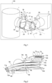
- FIG 2 shows, in a side view, layers 8a and 8b of electric cables held by two forks according to the invention.
- Each fork 6a or 6b comprises three fingers 9a-9c, 10a-10c respectively, and receives two superimposed layers 8a and 8b.
- the cables 7a, 7b, 7c, 7d and 7e in the same layer 8a are arranged side by side.
- the actuators are not shown; the junction piece 5 between the actuators, on which the guide forks 6a and 6b are fixed, appears very schematically and is only partially visible on the figure 3 ; it can be observed that it does not necessarily have the same shape as the junction piece of the first embodiment of the figure 1 .
- Each cable 7a or 7f is fixed at its two ends 11a and 11b or 12a and 12b respectively to the frame 4 and to the electrical device 1 to be supplied.
- the cables referenced 7a, 7f can for example slide relative to the fingers 9a-9c, 10a-10c of the forks 6a and 6b.
- the cable may slide relative to a fork in particular when the support point of the cable on the fork is not arranged on the axis of rotation resulting from the movement of the actuators.
- the length of the fingers makes it possible to hold the cable in the forks.
- Controlling the positions of the cables and controlling their curvatures thus makes it possible to control the torques exerted by these cables on the rotary actuators due to their stiffness, and in particular allows a high level of reliability and robustness of the system.
- the rotating actuators are stressed within their operating range. Many repetitive movements can therefore be carried out without maintenance operations.
- the cables are maintained within a determined guidance volume, the other constituent elements of the spacecraft being able to be arranged in complete safety outside this guidance volume.
- FIG 3 represents, in top view, the layers of electric cables held by two forks according to the arrangement of the figure 2
- the fingers of each fork are parallel to each other and protrude relative to the external cable 7e, 7f of each layer, so as to prevent the cables from leaving their guide path, in the event of movement of the cables relative to the fingers.
- the forks 6a and 6b are for example regularly distributed so as to have identical cable lengths between two support points.
- support point of a cable is understood to mean a point of attachment of the cable, for example at one of its ends, or a point of contact of the cable with a fork.
- the average length between two consecutive support points of a cable is, preferably, substantially the same along said cable. Of course, this length can vary according to the angular positions of the rotary actuators (hence the concept of average length).
- the length between two consecutive support points also varies from one cable to another, according to their position in the same layer or from one layer to another. For example, the average length between two support points of the internal cable 7a of the layer is less than the length of the external cable 7e of the layer and the variations in position of the external cable can be greater.
- the arrangement of the forks can be optimized in many different ways, in particular according to the constraints of each mission.
- the orientation system according to the invention is thus particularly adaptable to different space missions, for the orientation of one or more ion engines or other electrical devices to be powered.
Landscapes
- Engineering & Computer Science (AREA)
- Combustion & Propulsion (AREA)
- Chemical & Material Sciences (AREA)
- Aviation & Aerospace Engineering (AREA)
- Remote Sensing (AREA)
- Plasma & Fusion (AREA)
- Physics & Mathematics (AREA)
- Power Engineering (AREA)
- Mechanical Engineering (AREA)
- General Engineering & Computer Science (AREA)
- Electric Cable Arrangement Between Relatively Moving Parts (AREA)
- Manipulator (AREA)
- Navigation (AREA)
Claims (9)
- Raumfahrzeug (100), das Folgendes umfasst:- einen Rahmen (4),- eine elektrische Vorrichtung (1),- Elektrokabel (7a-7f) zur Stromversorgung und/oder Steuerung der elektrischen Vorrichtung,- mindestens zwei Drehantriebe (2a, 2b) zur Ausrichtung der elektrischen Vorrichtung (1) um zwei nicht parallele Drehachsen (Δa, Δb) herum,- ein Verbindungsbauteil (5) zwischen den beiden Drehantrieben, wobei einer der Drehantriebe (2a) einerseits mit der elektrischen Vorrichtung (1) und andererseits mit dem Verbindungsbauteil (5) verbunden ist, wobei der andere Drehantrieb (2b) einerseits mit dem Verbindungsbauteil (5) und andererseits mit dem Rahmen (4) verbunden ist, und- eine oder mehrere Lenkgabeln (6, 6a, 6b), die außerhalb des Verbindungsbauteils angeordnet sind, wobei jede der Lenkgabeln am Verbindungsbauteil (5) befestigt ist und Finger (9a, 9b, 9c; 10a, 10b, 10c) umfasst, die dazu konfiguriert sind, die Elektrokabel (7a-7f) zu tragen und zwischen den Fingern einen Führungspfad für die Elektrokabel (7a-7f) zu begrenzen,wobei jede Lenkgabel (6, 6a, 6b) derart angeordnet ist, dass, unabhängig von den Positionen der Drehantriebe (2a, 2b), die Elektrokabel (7a-7f) auf jeden der Drehantriebe (2a, 2b) ein Drehmoment ausüben, das geringer als eine Drehmomentkapazität des Drehantriebs ist,und wobei sich die Drehachsen (Δa, Δb) der Drehantriebe (2a, 2b) in einem Schnittpunkt (16) schneiden und mindestens eine der Lenkgabeln (6a, 6b, 6c) eine Hauptachse aufweist, die durch den Schnittpunkt (16) verläuft.
- Raumfahrzeug nach Anspruch 1, wobei die Lenkgabel(n) (6, 6a, 6b) jeweils einen Befestigungsschenkel (15) umfassen, der an einem ersten Ende am Verbindungsbauteil befestigt ist, wobei die Finger (9a, 9b, 9c; 10a, 10b, 10c) in der Form von Stangen vorliegen, die über eines ihrer Enden mit dem zweiten Ende des Befestigungsschenkel (15) fest verbunden sind.
- Raumfahrzeug nach Anspruch 1, wobei die Elektrokabel (7a-7f) im Verhältnis zu den Fingern (9a, 9b, 9c; 10a, 10b, 10c) jeder Lenkgabel (6, 6a, 6b) frei gleitend sind.
- Raumfahrzeug nach einem der Ansprüche 1 oder 2, wobei für jede Lenkgabel (6, 6a, 6b) die Finger (9a, 9b, 9c; 10a, 10b, 10c) der Lenkgabel geradlinig und parallel zueinander sind.
- Raumfahrzeug nach einem der Ansprüche 1 bis 3, wobei für jede Lenkgabel (6, 6a, 6b) die Finger (9a, 9b, 9c; 10a, 10b, 10c) der Lenkgabel in Bezug auf die Kabel (7a-7f) hervorstehen, um zu verhindern, dass die Kabel ihren Führungspfad verlassen.
- Raumfahrzeug nach einem der Ansprüche 1 bis 5, wobei mindestens eine der Lenkgabeln (6a, 6b) drei Finger, die zwei Abstände begrenzen, umfasst, um mindestens zwei übereinanderliegende Matten (8a, 8b) aus Elektrokabeln (7a-7f) aufzunehmen, wobei die Kabel in jeder der Matten (8a, 8b) Seite an Seite angeordnet sind.
- Raumfahrzeug nach einem der Ansprüche 1 bis 6, wobei die Lenkgabeln (6a, 6b) gleichmäßig entlang einer axialen Richtung der Kabel verteilt sind, um für jedes Kabel Kabelabschnitte mit im Wesentlichen gleicher Länge zwischen zwei Trägerpunkten zu haben.
- Raumfahrzeug nach einem der Ansprüche 1 bis 7, wobei jeder Drehantrieb einen Rotor und einen Stator umfasst und das Verbindungsbauteil (5) einerseits am Stator des Antriebs (2a), der mit der elektrischen Vorrichtung (1) verbunden ist, und andererseits am Rotor des Drehantriebs (2b) befestigt ist, der mit dem Rahmen (4) des Raumfahrzeugs verbunden ist.
- Raumfahrzeug (100) nach einem der Ansprüche 1 bis 8, wobei die elektrische Vorrichtung (1) ein Ionentriebwerk ist.
Applications Claiming Priority (2)
| Application Number | Priority Date | Filing Date | Title |
|---|---|---|---|
| FR2108922A FR3126403B1 (fr) | 2021-08-26 | 2021-08-26 | Système d’orientation pour dispositif électrique d’un engin spatial. |
| PCT/FR2022/051602 WO2023026011A1 (fr) | 2021-08-26 | 2022-08-23 | Engin spatial comprenant un dispositif électrique et un système d'orientation dudit dispositif électrique |
Publications (3)
| Publication Number | Publication Date |
|---|---|
| EP4334213A1 EP4334213A1 (de) | 2024-03-13 |
| EP4334213C0 EP4334213C0 (de) | 2025-02-19 |
| EP4334213B1 true EP4334213B1 (de) | 2025-02-19 |
Family
ID=79170665
Family Applications (1)
| Application Number | Title | Priority Date | Filing Date |
|---|---|---|---|
| EP22773272.4A Active EP4334213B1 (de) | 2021-08-26 | 2022-08-23 | Raumfahrzeug mit einer elektrischen vorrichtung und ausrichtungssystem für die elektrische vorrichtung |
Country Status (5)
| Country | Link |
|---|---|
| US (1) | US12338000B2 (de) |
| EP (1) | EP4334213B1 (de) |
| ES (1) | ES3022761T3 (de) |
| FR (1) | FR3126403B1 (de) |
| WO (1) | WO2023026011A1 (de) |
Family Cites Families (8)
| Publication number | Priority date | Publication date | Assignee | Title |
|---|---|---|---|---|
| US4465253A (en) | 1983-04-19 | 1984-08-14 | The United States Of America As Represented By The Secretary Of The Air Force | Flexible line support assembly |
| DE59601469D1 (de) | 1995-10-04 | 1999-04-22 | Austrian Aerospace Ges M B H | Antriebseinrichtung zum verstellen von zu orientierenden bauteilen eines satelliten |
| JP3815734B2 (ja) * | 2002-07-08 | 2006-08-30 | 矢崎総業株式会社 | 配線ユニットケーブル用ジョイントボックス |
| JP2012081528A (ja) * | 2010-10-06 | 2012-04-26 | Olympus Corp | 多関節ロボット |
| AT512487B1 (de) * | 2012-01-25 | 2016-05-15 | Ruag Space Gmbh | Stellmechanismus |
| FR3031502B1 (fr) * | 2015-01-14 | 2018-04-13 | Thales | Ensemble de pointage d'un instrument |
| EP3521179B1 (de) * | 2016-09-29 | 2021-05-26 | Mitsubishi Electric Corporation | Ausrichtungsmechanismus |
| US10022861B1 (en) * | 2017-04-27 | 2018-07-17 | Engineering Services Inc. | Two joint module and arm using same |
-
2021
- 2021-08-26 FR FR2108922A patent/FR3126403B1/fr active Active
-
2022
- 2022-08-23 WO PCT/FR2022/051602 patent/WO2023026011A1/fr not_active Ceased
- 2022-08-23 US US18/686,357 patent/US12338000B2/en active Active
- 2022-08-23 EP EP22773272.4A patent/EP4334213B1/de active Active
- 2022-08-23 ES ES22773272T patent/ES3022761T3/es active Active
Also Published As
| Publication number | Publication date |
|---|---|
| US12338000B2 (en) | 2025-06-24 |
| US20240359830A1 (en) | 2024-10-31 |
| FR3126403A1 (fr) | 2023-03-03 |
| EP4334213C0 (de) | 2025-02-19 |
| ES3022761T3 (en) | 2025-05-29 |
| FR3126403B1 (fr) | 2023-11-17 |
| EP4334213A1 (de) | 2024-03-13 |
| WO2023026011A1 (fr) | 2023-03-02 |
Similar Documents
| Publication | Publication Date | Title |
|---|---|---|
| EP2081829B1 (de) | Steuermomentkreisel und vorrichtung zu seiner montage | |
| CA2806661C (fr) | Dispositif de commande d'aubes pivotantes de turbomachine | |
| WO2004039673A1 (fr) | Ensemble articule de panneaux de generateur solaire et vehicule spatial | |
| EP1049950A1 (de) | Vorrichtung zur montage und lagekorrektur eines elementes, wie eines spiegels von einem weltraumteleskop | |
| EP3038923B1 (de) | Verfahren und vorrichtung für elektrischen satellitenantrieb | |
| FR2902763A1 (fr) | Articulation auto-motorisee pour ensemble articule tel qu'un panneau solaire de satellite | |
| EP3045396B1 (de) | Ausrichtungseinheit eines instrumentes | |
| FR2814216A1 (fr) | Dispositif d'orientation et systeme d'orientation embarque | |
| EP2990375B1 (de) | Mikromechanische vorrichtung mit elektromagnetischer betätigung | |
| EP4334213B1 (de) | Raumfahrzeug mit einer elektrischen vorrichtung und ausrichtungssystem für die elektrische vorrichtung | |
| FR2728695A1 (fr) | Dispositif de commande en rotation de grande precision, notamment pour telescope | |
| CA2479566C (fr) | Actionneur gyroscopique de pilotage de l'attitude d'un vehicule spatial | |
| WO2015101723A1 (fr) | Structure segmentée, en particulier pour réflecteur d'antenne de satellite, pourvue d'au moins un dispositif de déploiement à rotation et translation | |
| CA3165023C (fr) | Radiateur a ensoleillement reduit et systeme de guidage pour satellite geostationnaire | |
| EP4627400B1 (de) | Kompaktes einsetzbares optomechanisches system | |
| WO2021009425A1 (fr) | Tirant pour structure notamment en treillis | |
| EP2276926B1 (de) | Elektrische steuerrakete für ein raumschiff | |
| EP3804117A1 (de) | System zur schwingungsenergierückgewinnung | |
| EP0455543B1 (de) | Vorrichtung zur Ausrichtung einer Reflektorantenne | |
| WO2023041592A1 (fr) | Nouvelle architecture de système robotisé mobile | |
| WO2023135386A1 (fr) | Module de deploiement orbital avec un systeme de propulsion spatial a trois points | |
| EP3084884A1 (de) | Segmentierte struktur, insbesondere für einen satellitenantennenreflektors, mit mindestens einer einsatzvorrichtung mit einem parallelogramm | |
| WO2019063939A1 (fr) | Dispositif ameliore d'orientation d'engins spatiaux | |
| FR2876926A1 (fr) | Dispositif et installation de pliage d'un flan | |
| FR2846297A1 (fr) | Ensemble articule de panneaux de generateur solaire et vehicule spatial |
Legal Events
| Date | Code | Title | Description |
|---|---|---|---|
| STAA | Information on the status of an ep patent application or granted ep patent |
Free format text: STATUS: UNKNOWN |
|
| STAA | Information on the status of an ep patent application or granted ep patent |
Free format text: STATUS: THE INTERNATIONAL PUBLICATION HAS BEEN MADE |
|
| PUAI | Public reference made under article 153(3) epc to a published international application that has entered the european phase |
Free format text: ORIGINAL CODE: 0009012 |
|
| STAA | Information on the status of an ep patent application or granted ep patent |
Free format text: STATUS: REQUEST FOR EXAMINATION WAS MADE |
|
| 17P | Request for examination filed |
Effective date: 20231205 |
|
| AK | Designated contracting states |
Kind code of ref document: A1 Designated state(s): AL AT BE BG CH CY CZ DE DK EE ES FI FR GB GR HR HU IE IS IT LI LT LU LV MC MK MT NL NO PL PT RO RS SE SI SK SM TR |
|
| REG | Reference to a national code |
Ref country code: DE Free format text: PREVIOUS MAIN CLASS: B64G0001220000 Ref country code: DE Ref legal event code: R079 Ref document number: 602022010920 Country of ref document: DE Free format text: PREVIOUS MAIN CLASS: B64G0001220000 Ipc: B64G0001420000 |
|
| GRAP | Despatch of communication of intention to grant a patent |
Free format text: ORIGINAL CODE: EPIDOSNIGR1 |
|
| STAA | Information on the status of an ep patent application or granted ep patent |
Free format text: STATUS: GRANT OF PATENT IS INTENDED |
|
| RIC1 | Information provided on ipc code assigned before grant |
Ipc: H02G 3/32 20060101ALN20240904BHEP Ipc: H02G 3/04 20060101ALN20240904BHEP Ipc: B64G 1/40 20060101ALI20240904BHEP Ipc: B64G 1/42 20060101AFI20240904BHEP |
|
| RIC1 | Information provided on ipc code assigned before grant |
Ipc: H02G 3/32 20060101ALN20240909BHEP Ipc: H02G 3/04 20060101ALN20240909BHEP Ipc: B64G 1/40 20060101ALI20240909BHEP Ipc: B64G 1/42 20060101AFI20240909BHEP |
|
| DAV | Request for validation of the european patent (deleted) | ||
| DAX | Request for extension of the european patent (deleted) | ||
| INTG | Intention to grant announced |
Effective date: 20240919 |
|
| GRAS | Grant fee paid |
Free format text: ORIGINAL CODE: EPIDOSNIGR3 |
|
| GRAA | (expected) grant |
Free format text: ORIGINAL CODE: 0009210 |
|
| STAA | Information on the status of an ep patent application or granted ep patent |
Free format text: STATUS: THE PATENT HAS BEEN GRANTED |
|
| AK | Designated contracting states |
Kind code of ref document: B1 Designated state(s): AL AT BE BG CH CY CZ DE DK EE ES FI FR GB GR HR HU IE IS IT LI LT LU LV MC MK MT NL NO PL PT RO RS SE SI SK SM TR |
|
| REG | Reference to a national code |
Ref country code: GB Ref legal event code: FG4D Free format text: NOT ENGLISH |
|
| REG | Reference to a national code |
Ref country code: CH Ref legal event code: EP |
|
| REG | Reference to a national code |
Ref country code: IE Ref legal event code: FG4D Free format text: LANGUAGE OF EP DOCUMENT: FRENCH |
|
| REG | Reference to a national code |
Ref country code: DE Ref legal event code: R096 Ref document number: 602022010920 Country of ref document: DE |
|
| U01 | Request for unitary effect filed |
Effective date: 20250318 |
|
| U07 | Unitary effect registered |
Designated state(s): AT BE BG DE DK EE FI FR IT LT LU LV MT NL PT RO SE SI Effective date: 20250324 |
|
| REG | Reference to a national code |
Ref country code: ES Ref legal event code: FG2A Ref document number: 3022761 Country of ref document: ES Kind code of ref document: T3 Effective date: 20250529 |
|
| PG25 | Lapsed in a contracting state [announced via postgrant information from national office to epo] |
Ref country code: RS Free format text: LAPSE BECAUSE OF FAILURE TO SUBMIT A TRANSLATION OF THE DESCRIPTION OR TO PAY THE FEE WITHIN THE PRESCRIBED TIME-LIMIT Effective date: 20250519 |
|
| PG25 | Lapsed in a contracting state [announced via postgrant information from national office to epo] |
Ref country code: PL Free format text: LAPSE BECAUSE OF FAILURE TO SUBMIT A TRANSLATION OF THE DESCRIPTION OR TO PAY THE FEE WITHIN THE PRESCRIBED TIME-LIMIT Effective date: 20250219 |
|
| PG25 | Lapsed in a contracting state [announced via postgrant information from national office to epo] |
Ref country code: IS Free format text: LAPSE BECAUSE OF FAILURE TO SUBMIT A TRANSLATION OF THE DESCRIPTION OR TO PAY THE FEE WITHIN THE PRESCRIBED TIME-LIMIT Effective date: 20250619 Ref country code: NO Free format text: LAPSE BECAUSE OF FAILURE TO SUBMIT A TRANSLATION OF THE DESCRIPTION OR TO PAY THE FEE WITHIN THE PRESCRIBED TIME-LIMIT Effective date: 20250519 |
|
| PG25 | Lapsed in a contracting state [announced via postgrant information from national office to epo] |
Ref country code: HR Free format text: LAPSE BECAUSE OF FAILURE TO SUBMIT A TRANSLATION OF THE DESCRIPTION OR TO PAY THE FEE WITHIN THE PRESCRIBED TIME-LIMIT Effective date: 20250219 |
|
| PG25 | Lapsed in a contracting state [announced via postgrant information from national office to epo] |
Ref country code: GR Free format text: LAPSE BECAUSE OF FAILURE TO SUBMIT A TRANSLATION OF THE DESCRIPTION OR TO PAY THE FEE WITHIN THE PRESCRIBED TIME-LIMIT Effective date: 20250520 |
|
| U20 | Renewal fee for the european patent with unitary effect paid |
Year of fee payment: 4 Effective date: 20250827 |
|
| PG25 | Lapsed in a contracting state [announced via postgrant information from national office to epo] |
Ref country code: SM Free format text: LAPSE BECAUSE OF FAILURE TO SUBMIT A TRANSLATION OF THE DESCRIPTION OR TO PAY THE FEE WITHIN THE PRESCRIBED TIME-LIMIT Effective date: 20250219 |
|
| PGFP | Annual fee paid to national office [announced via postgrant information from national office to epo] |
Ref country code: ES Payment date: 20250926 Year of fee payment: 4 |
|
| PG25 | Lapsed in a contracting state [announced via postgrant information from national office to epo] |
Ref country code: CZ Free format text: LAPSE BECAUSE OF FAILURE TO SUBMIT A TRANSLATION OF THE DESCRIPTION OR TO PAY THE FEE WITHIN THE PRESCRIBED TIME-LIMIT Effective date: 20250219 |
|
| PG25 | Lapsed in a contracting state [announced via postgrant information from national office to epo] |
Ref country code: SK Free format text: LAPSE BECAUSE OF FAILURE TO SUBMIT A TRANSLATION OF THE DESCRIPTION OR TO PAY THE FEE WITHIN THE PRESCRIBED TIME-LIMIT Effective date: 20250219 |
|
| U1N | Appointed representative for the unitary patent procedure changed after the registration of the unitary effect |
Representative=s name: SANTARELLI; FR |
|
| PLBE | No opposition filed within time limit |
Free format text: ORIGINAL CODE: 0009261 |
|
| STAA | Information on the status of an ep patent application or granted ep patent |
Free format text: STATUS: NO OPPOSITION FILED WITHIN TIME LIMIT |
|
| REG | Reference to a national code |
Ref country code: CH Ref legal event code: L10 Free format text: ST27 STATUS EVENT CODE: U-0-0-L10-L00 (AS PROVIDED BY THE NATIONAL OFFICE) Effective date: 20251231 |
|
| 26N | No opposition filed |
Effective date: 20251120 |
|
| REG | Reference to a national code |
Ref country code: CH Ref legal event code: H13 Free format text: ST27 STATUS EVENT CODE: U-0-0-H10-H13 (AS PROVIDED BY THE NATIONAL OFFICE) Effective date: 20260324 |
|
| PG25 | Lapsed in a contracting state [announced via postgrant information from national office to epo] |
Ref country code: MC Free format text: LAPSE BECAUSE OF FAILURE TO SUBMIT A TRANSLATION OF THE DESCRIPTION OR TO PAY THE FEE WITHIN THE PRESCRIBED TIME-LIMIT Effective date: 20250219 |
|
| PG25 | Lapsed in a contracting state [announced via postgrant information from national office to epo] |
Ref country code: CH Free format text: LAPSE BECAUSE OF NON-PAYMENT OF DUE FEES Effective date: 20250831 |