EP4334540B1 - System und verfahren zur verwaltung von gasen in halbgeschlossenen fächern - Google Patents
System und verfahren zur verwaltung von gasen in halbgeschlossenen fächern Download PDFInfo
- Publication number
- EP4334540B1 EP4334540B1 EP22732672.5A EP22732672A EP4334540B1 EP 4334540 B1 EP4334540 B1 EP 4334540B1 EP 22732672 A EP22732672 A EP 22732672A EP 4334540 B1 EP4334540 B1 EP 4334540B1
- Authority
- EP
- European Patent Office
- Prior art keywords
- semi
- closed compartment
- gas
- fluid
- impeller
- Prior art date
- Legal status (The legal status is an assumption and is not a legal conclusion. Google has not performed a legal analysis and makes no representation as to the accuracy of the status listed.)
- Active
Links
Images





Classifications
-
- E—FIXED CONSTRUCTIONS
- E03—WATER SUPPLY; SEWERAGE
- E03D—WATER-CLOSETS OR URINALS WITH FLUSHING DEVICES; FLUSHING VALVES THEREFOR
- E03D9/00—Sanitary or other accessories for lavatories ; Devices for cleaning or disinfecting the toilet room or the toilet bowl; Devices for eliminating smells
- E03D9/04—Special arrangement or operation of ventilating devices
- E03D9/05—Special arrangement or operation of ventilating devices ventilating the bowl
- E03D9/052—Special arrangement or operation of ventilating devices ventilating the bowl using incorporated fans
-
- E—FIXED CONSTRUCTIONS
- E03—WATER SUPPLY; SEWERAGE
- E03C—DOMESTIC PLUMBING INSTALLATIONS FOR FRESH WATER OR WASTE WATER; SINKS
- E03C1/00—Domestic plumbing installations for fresh water or waste water; Sinks
- E03C1/12—Plumbing installations for waste water; Basins or fountains connected thereto; Sinks
- E03C1/28—Odour seals
- E03C1/284—Odour seals having U-shaped trap
-
- E—FIXED CONSTRUCTIONS
- E03—WATER SUPPLY; SEWERAGE
- E03D—WATER-CLOSETS OR URINALS WITH FLUSHING DEVICES; FLUSHING VALVES THEREFOR
- E03D1/00—Water flushing devices with cisterns ; Setting up a range of flushing devices or water-closets; Combinations of several flushing devices
-
- E—FIXED CONSTRUCTIONS
- E03—WATER SUPPLY; SEWERAGE
- E03D—WATER-CLOSETS OR URINALS WITH FLUSHING DEVICES; FLUSHING VALVES THEREFOR
- E03D9/00—Sanitary or other accessories for lavatories ; Devices for cleaning or disinfecting the toilet room or the toilet bowl; Devices for eliminating smells
- E03D9/04—Special arrangement or operation of ventilating devices
- E03D9/05—Special arrangement or operation of ventilating devices ventilating the bowl
-
- F—MECHANICAL ENGINEERING; LIGHTING; HEATING; WEAPONS; BLASTING
- F24—HEATING; RANGES; VENTILATING
- F24C—DOMESTIC STOVES OR RANGES ; DETAILS OF DOMESTIC STOVES OR RANGES, OF GENERAL APPLICATION
- F24C15/00—Details
- F24C15/20—Removing cooking fumes
-
- E—FIXED CONSTRUCTIONS
- E03—WATER SUPPLY; SEWERAGE
- E03C—DOMESTIC PLUMBING INSTALLATIONS FOR FRESH WATER OR WASTE WATER; SINKS
- E03C1/00—Domestic plumbing installations for fresh water or waste water; Sinks
- E03C1/12—Plumbing installations for waste water; Basins or fountains connected thereto; Sinks
- E03C1/28—Odour seals
- E03C1/284—Odour seals having U-shaped trap
- E03C1/288—Odour seals having U-shaped trap having non-return valves against return of waste water
-
- E—FIXED CONSTRUCTIONS
- E03—WATER SUPPLY; SEWERAGE
- E03D—WATER-CLOSETS OR URINALS WITH FLUSHING DEVICES; FLUSHING VALVES THEREFOR
- E03D1/00—Water flushing devices with cisterns ; Setting up a range of flushing devices or water-closets; Combinations of several flushing devices
- E03D1/30—Valves for high or low level cisterns; Their arrangement ; Flushing mechanisms in the cistern, optionally with provisions for a pre-or a post- flushing and for cutting off the flushing mechanism in case of leakage
- E03D1/33—Adaptations or arrangements of floats
Definitions
- the present invention generally relates to gas management systems and methods directed at removing undesirous gasses from semi-closed spaces, and more particularly, to semi-closed compartment gas management systems and methods configured to dispose of undesirous gases into discharge means.
- Gas management systems and methods are directed at removing undesirous gasses from semi-closed spaces such as toilets, kitchens, eating halls (e.g., restaurants), laboratories and other private and publicly used spaces. Such removal of gas may be desirous so as to remove bad/unpleasant/hazardous gasses/odors that may accumulate in semi-closed spaces and pose a disturbance to a user's comfort, health, safety, etc.
- Patent publication US7380292B discloses a toilet modular system comprising an automatic toilet ventilator which vacuums objectionable odor from a toilet bowl and exhausts it to the sewer discharge pipeline and further comprising a gas backflow prevention mechanism that uses a "ball trap" construction.
- Patent publication GB2305944A discloses a water tank spilling tube structure with a gas exhaustion function comprising a sucking pump, wherein the sucking pump is controlled by the throttle which is switched on/off by a floating ball.
- Patent publication DE3534494A1 discloses a device serves for the control of at least one gas stream passing through at least one pipe and utilizes a liquid supply that passes with an outflow end and an incoming flow flowing into the liquid supply, wherein said device may be used for the event of fire extinguishing of ventilation channels and others applications, such as the ventilation of toilet bowl.
- Patent application WO9735075A1 discloses an odor removing system for a toilet consisting a blower having its inlet connected to a toilet bowl and an outlet connected to a discharge sewer pipeline, wherein the blower is driven by a rotary water motor which is actuated by water entering the initially empty toilet tank.
- Patent application WO2014136120A1 discloses an odor removing system for a toilet configured to remove bad odors and diverting them to the sewage pipeline, wherein an external siphon/water lock line, located outside the toilet tank is further configured to restrict the return flow of diverted gas from the sewer pipeline.
- Patent publication US5361422A discloses a toilet ventilating system for use with a toilet bowl incorporating a sewer line connection and including an upstanding vent conduit leading from a bowl rim outlet to an elevated cross over in the water storage tank and then dropping downwardly to form an exhaust conduit connected with the sewer pipeline and further comprising a fluid barrier trap valve having a tight seal float component.
- the present invention discloses a cost effective efficient and smart gas management system and method for safe removal of undesirous gas through readily available discharge means.
- the present invention further discloses a gas management system and method comprising a reliable and autonomous block prevention means configured to mitigate the tendency of conduit systems to gradually/abruptly develop blockages from various reasons.
- the gas flow created by the impeller is induced by drawing air through a conduit inlet being in communication with a toilet bowl
- the fluid barrier receptacle is configured to be located within a toilet tank and comprising an inlet aperture configured to enable flow of water from the water tank into the fluid barrier receptacle
- the fluid barrier receptacle further comprising a float component configured to be vertically adjustable in accordance with the water level within the toilet tank, wherein the float component is configured to operate as an autonomous block prevention means by comprising a protrusion having a clearance gap fit with the fluid inlet aperture
- the gas drawn by the impeller is configured to be discharged into a sewer pipeline as a discharge means
- the fluid barrier receptable is configured to block odors originated in the sewer pipeline from spreading to the toilet bowl
- said protrusion is configured to alternately fit (i.e. alternate between positions such as in/out or partially in/out) with the inlet aperture in accordance with the water level in the toilet tank.
- the protrusion is a rod having ridges and grooves.
- the conduit is configured to connect to an over-flow pipe forming a part of a toilet bowl flushing device.
- the impeller is configured to be acoustically isolated.
- the semi-closed compartment gas management system is configured by modular commercially available components.
- the semi-closed compartment gas management system is configured to be compactly fitted and installed within commercially available toilet bowl flushing systems.
- the fluid barrier receptacle is configured to be filled with fluid entering through the inlet aperture.
- the fluid barrier receptacle is configured to be filled with fluid sourced from a pre-contained reservoir entering through the inlet aperture.
- the float component is configured as a fluid reservoir of toilet tank water contained in said float component prior or during flushing and designated to enter the float component through the inlet aperture upon termination of gas removal action.
- the semi-closed compartment gas management system further comprising means for sampling the drawn gas in the conduit and at least one sensor, wherein the sample is designated to be exposed to the sensor.
- the at least one sensor is configured to collect data regarding the sampled drawn gas.
- the semi-closed compartment gas management system further comprising a controller configured to diagnose collected data by analyzing the at least one sensor output data.
- the semi-closed compartment gas management system is configured to transmit the gathered data to a designated device or data center for further analysis or display.
- transmittal of the gathered data is conducted on an immediate real-time basis.
- the semi-closed compartment is a fume hood and wherein the system is configured to draw air from inner cavity of the exhaust hood and dispose it into a discharge pipe.
- the alternating operation of the block prevention means is configured to prevent or remove scale deposits from the inlet aperture.
- the power source is a rechargeable power reservoir that may be configured to be charged by a water flow created when a toilet tank is filled and/or be charged wirelessly.
- the fluid barrier receptable is configured to be filled with 20-250mm of water and/or configured to be in a U-shaped conduit and/or has a compact siphon configuration.
- the inlet aperture is configured to allow entrance of fluid filling the water barrier receptable and wherein upon operation the impeller is configured to draw water in the water barrier receptacle and dispose of it into the sewer pipeline.
- the semi-closed compartment gas management system is operatable by a remote control.
- the semi-closed compartment gas management system is operatable by a wireless control means (such as cellular, Bluetooth or Wi-Fi application).
- a wireless control means such as cellular, Bluetooth or Wi-Fi application.
- the fluid inlet aperture further comprising a float component vertically adjustable in accordance with the water level within a toilet tank and configured to operate as an autonomous block prevention means by using a protrusion having a clearance gap fit with the fluid inlet aperture.
- Controller refers to any type of computing platform or component that may be provisioned with a Central Processing Unit (CPU) or microprocessors, and may be provisioned with several input/output (I/O) ports, for example, a general-purpose computer such as a personal computer, laptop, tablet, mobile cellular phone, controller chip, SoC or a cloud computing system.
- CPU Central Processing Unit
- I/O input/output
- the current invention discloses a semi-closed compartment gas management system configured to create an airflow and disposed it in order to remove gas from a semi-closed compartment and prevent it from spreading.
- the semi-closed compartment gas management system is configured to form a part of a toilet sanitary hardware, and be stored within a toilet tank.
- the gas management system may be configured by modular commercially available components.
- an impeller configured to create an air stream may be a commercially available blower/fan (for example, a 12V blower), the various conduits forming a part of the gas management system may be available stock parts.
- utilizing commercially available components to construct the semi-closed compartment gas management system may benefit the system serviceability by enabling the use of widely available spare parts and allowing supply of low-priced components.
- the impeller may be configured to be acoustically isolated such that the operation of the semi-closed compartment gas management system will not cause any disturbance to the user.
- the semi-closed compartment gas management system may be configured to compactly be fitted and installed within a commercially available toilet tank, fume exhaust/hood, etc.
- the semi-closed compartment gas management system may further comprise means for sampling the drawn gas within the conduit and at least one sensor configured to analyze said sample.
- the sensor may be configured to collect data regarding the sampled drawn gas.
- the semi-closed compartment gas management system installed within a toilet bowl may be configured to analyze the bio-medical condition of a user by sampling gas generated by said user digestion system or diagnose the characteristics of unpleasant gas odors during and after a user uses the toilet bowl.
- the semi-closed compartment gas management system coupled with a laboratory fume hood may be configured to perform real time analysis of laboratory work products and identify hazardous material situations.
- the semi-closed compartment gas management system may comprise a controller configured to diagnose collected data by analyzing the sensor output data.
- the gathered data may be transmitted to a designated device or data center for further analysis or display.
- said transmittal of the gathered data may be conducted on an immediate real-time basis in order to provide a fast detection system.
- the semi-closed compartment gas management system is configured to be driven by a power source and create a gas flow.
- the impeller may be powered by a wall socket electrical connection, by a power reserve such a battery or by a mechanical dynamo creating electricity using the water flow created when a toilet tank is filled.
- the semi-closed compartment gas management system may be configured be driven by a power reserve that can be wirelessly charge, for example, by utilizing inductive charging.
- the semi-closed compartment gas management system may be operable by a remote control or by any wireless control means such as a cellular RF, Bluetooth or Wi-Fi application, etc.
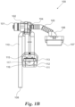
- an impeller 102 is configured to be driven by a power source and create a gas flow.
- impeller 102 may be a blower configured to create an air stream.
- impeller 102 may be powered by a wall socket electrical connection/ by a power reserve such a battery/ by a mechanical mechanism converting water stream to electricity/ by inductive charging, etc.
- impeller 102 is configured to create a gas flow passing through conduit inlet 104, along conduit 110 to be discharged through conduit outlet 108 to a discharge means such as a sewer pipeline, wherein conduit inlet 104 may be configured to be in communication with a semi-closed compartment.
- a semi-closed compartment may be any receptacle/chamber having an inner volume that is not completely sealed to its outer environment.
- a semi-closed compartment may be a restroom, a kitchen, a restaurant, a laboratory, an exhaust hood, a toilet bawl, etc.
- conduit inlet 104 may further be configured to connect to an adaptor 106 having a connector 107 configured to be connected to the semi-closed compartment.
- a resilient tube 105 may be configured to connect inlet 104 with adaptor 106.
- a fluid barrier receptacle 112 may be configured with a fluid inlet aperture 116 and designated to be installed at any point along conduit 110.
- fluid barrier receptacle 112 may have a siphon configuration, for example, fluid barrier receptacle 112 may be a siphon shaped as an inverted "U" shaped conduit (shown on FIG. 2A & 2B disclosed hereinafter), configured to be surrounded by a receptacle 111.
- receptacle 111 may be configured to contain some amount of fluid by preserving a constant amount of water even when the water level within the toilet tanks 10 is low. This configuration provides a barrier against unpleasant odors by allowing fluid to enter the fluid inlet aperture 116 even when the toilet tank 10 is not full or empty.
- receptacle 111 may be filled with a pre-contained fluid reservoir. This configuration provides a barrier against unpleasant odors by allowing fluid to enter the fluid inlet aperture 116 even when the toilet tank 10 is empty for long period of time, or alternatively, when the semi-closed compartment gas management system 100 is configured to be installed in a hosting system that lacks a water tank.
- fluid barrier receptacle 112 may further comprise a float section 113 configured to vertically move along conduit 110.
- the float section 113 is restricted to move along a designated path, for example, float section 113 may be restricted to vertically move along tracks 115.
- the fluid barrier receptacle 112 is configured to block gas originating from the discharge means from spreading to the semi-closed compartment while the impeller 102 is not operating, by providing a receptacle full of fluid, thus preventing gasses from passing and spreading.
- receptacle 111 which covers fluid barrier receptacle 112 is configured to provide protective shield to fluid barrier receptacle 112 such that various objects present within the toilet tank 10 are unable to penetrate/block the fluid inlet aperture 116.
- toilet tanks sometimes include a loosen pneumatic cable that plays a part in the flushing mechanism, receptacle 111 which covers fluid barrier receptacle 112 may provide a barrier between said pneumatic cable and the fluid inlet aperture 116 such that the fluid inlet aperture 116 will not be clogged by said pneumatic cable, thus enhancing the system's reliability.
- fluid barrier receptacle 112 is configured to be filled with 20-250 mm of water.
- the water level minimal height depends on the diameter of conduit 110 and maximal height depends on impeller 102 power to exert fluid upon operation of the semi-closed compartment gas management system 100 and removal of water from the barrier receptacle 112.
- said ability of the semi-closed compartment gas management system 100 to operate by implementing various fluid barrier receptacles 112 having various diameters configured to be filled with various amounts of fluid leads to high versatility of said system.
- the semi-closed compartment gas management system 100 may be configured to work with various impellers 102 having various outputs.
- a fluid barrier receptacle 112 having a diameter of 250 millimeter is configured to filled with a relatively large amount of fluid, and thus be configured to form a part of a system having relatively strong gas drawing output, or, alternatively, be configured to connect to a relatively large diameter conduits of a system, and vice versa.
- said high versatility of the semi-closed compartment gas management system 100 may be beneficial in installing it in various hosting systems such as fume exhaust/hood a kitchen, restaurant, laboratory, etc.
- float 113 is equipped with block prevention means configured to be autonomously utilized upon a vertical movement of float 113 to prevent or remove any blockage such as scale deposits from the inlet aperture 116.
- impeller 102 may be anchored to its position by a resilient connector 101.
- impeller 102 may be anchored to a toilet tank 10 by a resilient connector 101 that may be made out of rubber, polymer, etc.
- connector 101 may be configured to be acoustically isolated such that the operation of impeller 102 /the semi-closed compartment gas management system 100 will not cause any disturbance to the user.
- connector 101 may be configured to reduce vibrations caused by the operation of impeller 102 such that the operation of the semi-closed compartment gas management system 100 will not cause any disturbance to the user.
- float 113 is equipped with block prevention means configured to be autonomously utilized upon a vertical movement of float 113.
- float 113 is configured to prevent or remove deposits (such as scale deposits, etc.) from the inlet aperture 116 by utilizing its block prevention means equipped with protrusion 117 which is designated to alternatively enter/out to/from fluid inlet aperture 116.
- the protrusion 117 is a rod having ridges and grooves such as a screw, etc., wherein said ridges are adapted to remove scale deposits by scrubbing the inner diameter of inlet aperture 116 while float 113 moves vertically.
- FIG. 1C schematically illustrates a semi-closed compartment gas management system 100 illustrated in FIG. 1A and 1B and further configured to be installed within toilet tank 10.
- an impeller 102 is configured to be driven by a power source and create a gas flow by drawing air through a conduit inlet 104 being in communication with a toilet flushing device 200 and, in turn, from the semi-closed compartment created by a toilet bowl (not shown).
- conduit 110 comprises a conduit outlet 108 configured to discharge gas to a sewer pipeline in order to remove bad odors from the toilet bowl and prevent it from spreading within the toilet chamber.
- a fluid barrier receptacle 112 may be configured with a fluid inlet aperture 116 and wherein fluid barrier receptacle 112 is designated to be installed at any point along conduit 110.
- Fluid barrier receptacle 112 may further comprise a float section 113 configured to vertically move along conduit 110 in accordance with the water level in toilet tank 10. According to some embodiments, the float section 113 is restricted to vertically move along tracks 115. According to some embodiments, the fluid barrier receptacle 112 is configured to block gas originating from sewer pipeline from spreading to the semi-closed compartment.
- fluid barrier receptacle 112 provides a fluid barrier preventing gasses from passing and spreading to the semi closed compartment.
- receptacle 111 may be configured to store some amount of fluid designated to flow from the toilet tank 10 through the fluid inlet aperture 116 and fill fluid barrier receptacle 112, thus blocking gases from the sewer pipeline to flow into the toilet bowl.
- water entering fluid barrier receptacle 112 through the inlet aperture 116 are discharged to the sewer pipeline through conduit outlet 108.
- float 113 may be equipped with block prevention means (comprising protrusion 117 shown in FIG. 1B ) configured to be autonomously utilized upon a vertical movement of float 113.
- block prevention means comprising protrusion 117 shown in FIG. 1B
- float 113 may be configured to prevent or remove scale deposits from the inlet aperture 116 by utilizing its block prevention means that such as protrusion 117 designated to alternatively enter/out to/from fluid inlet aperture 116.
- the toilet tank 10 may comprise an opening 103 configured to provide access to its inner components for the purpose of service, maintenance, upgrades, etc.
- the semi-closed compartment gas management system 100 may be configured to be narrower from opening 103 such that it may be inserted and removed without a need of complicated disassembly of the toilet tank 10. This modular design provides a versatile system, ready to be installed in various commercially available toilet tanks.
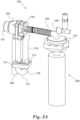
- FIG. 2A & 2B schematically illustrate another embodiment of a semi-closed compartment gas management system 100 configured to be installed within toilet tank 10.
- an impeller 102 is configured to be driven by a power source and create a gas flow by drawing air through a conduit inlet 104 being in communication with a toilet flushing device 200, and, in turn, from the semi-closed compartment created by a toilet bowl (not shown), to be discharged into a sewer pipeline through outlet conduit 108.
- water entering the U-shaped section of conduit 110 through the inlet aperture 116 are discharged to the sewer pipeline through conduit outlet 108.
- float component 113 and protrusion 117 are configured to vertically move along tracks 115, hence alternately fit with the inlet aperture 117 in accordance to the water level in toilet tank 10. According to some embodiments, the alternating operation of the float component 113 and protrusion 117 is configured to prevent or remove scale deposits from inlet aperture 116.
- said protrusion 117 is configured to alternately fit with the inlet aperture 116 in accordance with the water level in the toilet tank 10, thus, alternatively prevent or remove any blockage such as scale deposits from the inlet aperture 116.
- impeller 102 may be anchored to its position by a resilient connector 101.
- impeller 102 may be anchored to a toilet tank 10 of by a resilient connector 101 that may be made out of rubber, polymer, etc.
- connector 101 may be configured to be acoustically isolated such that the operation of impeller 102 /the semi-closed compartment gas management system 100 will not cause any disturbance to the user.
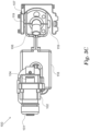
- FIGS. 3A-3C schematically illustrate multiple views of another embodiment of a semi-closed compartment gas management system 100 configured to be installed within toilet tank 10.
- an impeller 102 is configured to be driven by a power source and create a gas flow by drawing air through a conduit inlet 104 being in communication with a toilet flushing device 200, and, in turn, from the semi-closed compartment created by a toilet bowl (not shown).
- receptacle 111 may be configured to contain some amount of fluid by preserving a constant amount of water even when the water level within the toilet tanks 10 is low. This configuration provides a barrier against unpleasant odors by allowing fluid to enter the fluid inlet aperture 116 even when the toilet tank 10 is not full or empty.
- receptacle 111 may be filled with a pre-contained fluid reservoir. This configuration provides a barrier against unpleasant odors by allowing fluid to enter the fluid inlet aperture 116 even when the toilet tank 10 empty for a long period of time is empty for long period of time, or, alternatively, when the semi-closed compartment gas management system 100 is configured to be installed in a hosting system that lacks a water tank.
- conduit inlet 104 may further be configured to connect to an adaptor 106 having a connector 107 configured to be connected to toilet flushing device 200, wherein the gas drawn by the impeller 102 is configured to be drawn through an over-flow pipe (not shown) forming a part of toilet flushing device 200, and, in turn, from the semi-closed compartment created by a toilet bowl (not shown) to be discharged into a sewer pipeline through outlet conduit 108.
- this allows the semi-closed compartment gas management system 100 to remove bad odors from the toilet bowl and prevent it from spreading within the toilet chamber.
- a fluid barrier receptacle 112 may be configured with a fluid inlet aperture 116 (shown in FIGS 1 & 2 ) and designated to be installed at any point along conduit 110.
- fluid barrier receptacle 112 may further comprise a float section 113 configured to vertically move along conduit 110.
- float section 113 is restricted to vertically move along tracks 115.
- the fluid barrier receptacle 112 is configured to block gas originating from sewer pipeline from spreading to the semi-closed compartment.
- fluid barrier receptacle 112 provides a fluid barrier preventing gasses from passing and spreading by storing a relatively small amount of water designated to flow from the toilet tank 10 through the fluid inlet aperture and fill it, thus blocking gases from the sewer pipeline to flow into the toilet bowl.
- water entering fluid barrier receptacle 112 through the inlet aperture 116 are discharged to the sewer pipeline through conduit outlet 108.
- float 113 may be further equipped with block prevention means configured to be utilized upon a vertical movement of float 113 to prevent or remove any blockage such as scale deposits from the inlet aperture.
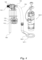
- a float 118 may be configured to be connected to flushing device 200 and provide levering mechanism controlling the water level within toilet tank 10. According to some embodiments, float 118 may be configured to be installed upon a flushing device and provide a malfunction protection in case of unregulated water level within the toilet tank 10.
- a float 118 may be configured to be mounted upon a generic float mechanism associated with a generic flushing device in order to enable installation of the semi-closed compartment gas management system 100 within a commercially available toilet tank.
- float 118 may be configured to manipulate the flushing mechanism in case of water within the toilet tank 10 rising above a certain pre-designated level (for example, 6 liters, 9 liters, etc.) that may cause a spillage.
- the lever connected to float 118 may be configured to lift a valve (not shown) which in turn may allow rising water to be evacuated to the discharge means.
- the lever connected to float 118 may be configured to lift said valve by lifting designated protrusion/s 119, thus allow rising water to be evacuated to the discharge means.
- float 118 may have a compact shape/size due to the presence of the semi-closed compartment gas management system 100 within the limited space of the toilet tank 10.
- float 118 may form a U-shape having two lobes configured to spread around the gas management system 100 such that the lobes are located outwardly and laterally to conduit 110.
- float 118 may be in any shape or form that exhibit a compact design designated to save room within toilet tank 10.
- impeller 102 may be anchored to its position by a resilient connector 101.
- impeller 102 may be anchored to a toilet tank of by a resilient connector 101 that may be made out of rubber, polymer, etc.
- connector 101 may be configured to be acoustically isolated such that the operation of impeller 102 /the semi-closed compartment gas management system 100 will not cause any disturbance to the user.
- connector 101 may be configured to reduce vibrations caused by the operation of impeller 102 such that the operation of the semi-closed compartment gas management system 100 will not cause any disturbance to the user.
- an impeller 102 is configured to be driven by a power source and create a gas flow by drawing air through a conduit inlet 104 being in communication with the lower side of toilet flushing device 200.1, and, in turn, from the semi-closed compartment created by a toilet bowl (not shown) to be discharged into a sewer pipeline through outlet conduit 108. According to some embodiments, this allows the semi-closed compartment gas management system 100 to remove bad odors from the toilet bowl and prevent it from spreading within a toilet chamber.
- receptacle 111 may be configured to contain some amount of fluid by preserving a constant amount of water even when the water level within the toilet tanks 10 is low. This configuration provides a barrier against unpleasant odors by allowing fluid to enter the fluid inlet aperture 116 even when the toilet tank 10 is not full or empty.
- receptacle 111 may be filled with a pre-contained fluid reservoir. This configuration provides a barrier against unpleasant odors by allowing fluid to enter the fluid inlet aperture 116 even when the toilet tank 10 empty a long period of time.
- impeller 102 may be anchored to its position by a resilient connector 101.
- impeller 102 may be anchored to a toilet tank of by a resilient connector 101 that may be made out of rubber, polymer, etc.
- connector 101 may be configured to be acoustically isolated such that the operation of impeller 102 /the semi-closed compartment gas management system 100 will not cause any disturbance to the user.
- connector 101 may be configured to reduce vibrations caused by the operation of impeller 102 such that the operation of the semi-closed compartment gas management system 100 will not cause any disturbance to the user.
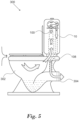
- FIG. 5 schematically illustrates a semi-closed compartment gas management system 100 configured to be installed within a commercially available toilet assembly 300.
- semi-closed compartment gas management system 100 is configured to be installed within toilet tank 10, and, upon operation, draw gas from the toilet bawl 302 and into sewage pipeline 304.
- the direction of the arrows indicates the direction of gas flowing from bawl 302 and into sewage pipeline 304 such that a constant sub-pressure is created within toilet bowl 302 and prevents gases/unpleasant odors from spreading.
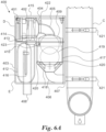
- FIGS. 6A & 6B schematically illustrates a semi-closed compartment gas management system 400 as examples of the invention.
- the semi-closed compartment gas management system 400 may be configured to connect to a pipe C that provides fluids to a semi-closed compartment.
- a semi-closed compartment gas management system 400 may be configured to be attached to a water pipe providing water flow to a toilet cistern.
- an impeller 402 is configured to be driven by a power source and create a gas flow.
- impeller 402 may be a blower configured to create an air stream.
- impeller 402 may be powered by a wall socket electrical connection/ by a power reserve such a battery/ by a mechanical mechanism converting water stream to electricity/ by inductive charging, or any other known powering technology.
- impeller 402 may be configured to create a gas flow passing through a conduit comprising different sections.
- impeller 402 may be configured to create a gas flow passing through a conduit inlet 404, along conduit section 410 and discharged through conduit outlet 408 to a discharge means such as a sewer pipeline.
- a semi-closed compartment may be any receptacle/chamber having an inner volume that is not completely sealed to its outer environment.
- a semi-closed compartment may be a restroom, a kitchen, a restaurant, a laboratory, an exhaust hood, a toilet bawl, etc.
- an adaptor 406 having a connector 407 may be configured to be directly connected to the semi-closed compartment through pipe C.
- trap valve 417 is adapted to connect to adaptor 406 from one side, and to the conduit inlet 404 from another side.
- conduit inlet 404 may be connected through conduit section 405 to cup 409 designated to provide a cover to trap valve 417.
- casing 403 is configured to contain some amount of fluid by preserving a constant amount of fluid within the inner volume of the semi-closed compartment gas management system 400. This configuration provides a barrier against unpleasant odors by allowing fluid to enter the fluid inlet aperture 416 and fill the fluid barrier receptacle 412 when the impeller 402 is not operating.
- the inner volume of the semi-closed compartment gas management system 400 is configured to be separated by partition 413, thus creating inner volumes D and E surrounded by casing 403.
- partition 413 may further comprise opening 414 configured to be alternatively sealed with a lid (not shown).
- opening 414 may allow the insertion of a designated prob/rod configured to penetrate into aperture 416 in order to remove any blockage such as scale deposits, etc.
- the rod may be equipped with ridges and grooves (for example, screw, etc.), wherein said ridges are adapted to remove scale deposits by scrubbing the inner diameter of aperture 416.
- connector 401 may be configured to reduce vibrations caused by the operation of impeller 402 such that the operation of the semi-closed compartment gas management system 400 will not cause any disturbance to the user.
- the semi-closed compartment gas management system 400 may further comprise means for sampling the drawn gas from pipe C and at least one sensor configured to analyze said sample.
- the sensor may be configured to collect data regarding the sampled drawn gas.
- the semi-closed compartment gas management system 400 installed on pipe C providing water flow to a toilet bowl may be configured with diagnosis passageway/s 422 allowing gas to flow from the semi close compartment and reach a sensor (not shown) configured to analyze the bio-medical condition of a user by sampling gas generated by said user digestion system or diagnose the characteristics of various gas odors during and after a user uses the toilet bowl.
- the semi-closed compartment gas management system 400 coupled with a laboratory fume hood may be configured to perform real time analysis of laboratory work products and identify hazardous material situations.
- the semi-closed compartment gas management system 400 may comprise a controller configured to diagnose collected data by analyzing the sensor output data.
- the gathered data may be transmitted to a designated device or data center for further analysis or display.
- said transmittal of the gathered data may be conducted on an immediate real-time basis in order to provide a fast detection system.
Landscapes
- Health & Medical Sciences (AREA)
- Public Health (AREA)
- Engineering & Computer Science (AREA)
- Water Supply & Treatment (AREA)
- Life Sciences & Earth Sciences (AREA)
- Hydrology & Water Resources (AREA)
- Epidemiology (AREA)
- Chemical & Material Sciences (AREA)
- Combustion & Propulsion (AREA)
- Mechanical Engineering (AREA)
- General Engineering & Computer Science (AREA)
- Environmental & Geological Engineering (AREA)
- Sanitary Device For Flush Toilet (AREA)
- Transition And Organic Metals Composition Catalysts For Addition Polymerization (AREA)
Claims (15)
- Gasmanagementsystem (100) für einen halbgeschlossenen Raum, welches aufweist:(i) eine Energiequelle,(ii) ein Lüfterrad (102), das so konfiguriert ist, dass es von der Energiequelle angetrieben wird und einen Gasstrom erzeugt,(iii) eine Leitung mit einem Gaseinlass (104), der mit einem halbgeschlossenen Raum in Verbindung steht, und einem Auslass (108), der mit einem Auslassmittel verbunden ist,(iv) einen Sperrflüssigkeitsaufnehmer (112), der eine liegende Flüssigkeitseinlassöffnung (116) aufweist und konfiguriert ist um mit der Leitung zwischen ihrem Gaseinlass (104) und ihrem Auslass (108) verbunden zu sein und ferner einen Schwimmer (113) aufweist,wobei der durch das Lüfterrad (102) erzeugte Gasstrom dazu bestimmt ist, aus dem halbgeschlossenen Raum (100) und durch die Leitung zu strömen und wobei der Sperrflüssigkeitsaufnehmer (112) so konfiguriert ist, dass er verhindert, dass sich Gas, das vom Auslassmittel stammt, in den halbgeschlossenen Raum (100) ausbreitet, während das Lüfterrad (102) nicht in Betrieb ist, undwobei der Schwimmer (113) vertikal veränderlich und so konfiguriert ist, dass er autonom arbeitet, um eine Blockierung durch Verwendung eines Vorsprungs (117) zu verhindern, welcher als Stange mit Rippen und Nuten ausgebildet ist und eine Spielpassung mit der Flüssigeinlassöffnung (116) hat,wobei der alternierende Betrieb des Schwimmers (113), welcher den Vorsprung (117) umfasst, der in die Einlassöffnung (116) eintritt und aus dieser austritt, so konfiguriert ist, dass er Ablagerungen an der Einlassöffnung (116) verhindert oder entfernt.
- System nach Anspruch 1, wobei:der durch das Lüfterrad (102) erzeugte Gasstrom durch das Ansaugen von Luft durch den Leitungseinlass (104) induziert wird, der mit einer Toilettenschüssel in Verbindung steht, die als halbgeschlossener Raum fungiert,der Sperrflüssigkeitsaufnehmer (112) so konfiguriert ist, dass er sich in einem Toilettentank befindet und die Einlassöffnung (116) aufweist, die so konfiguriert ist, dass sie Wasserfluss vom Wassertank in den Sperrflüssigkeitsaufnehmer (112) ermöglicht,wobei der Sperrflüssigkeitsaufnehmer (112) ferner den Schwimmer (113) außerhalb des Sperrflüssigkeitsaufnehmers (112) aufweist,wobei das vom Lüfterrad (102) angesaugte Gas in eine Abwasserleitung abgegeben wird, die als Auslassmittel dient,wobei der Sperrflüssigkeitsaufnehmer (112) so konfiguriert ist, dass er verhindert, dass sich in der Abwasserleitung entstehende Gerüche in die Toilettenschüssel ausbreiten, undwobei der Vorsprung (117) so konfiguriert ist, dass er in Abhängigkeit vom Wasserstand im Spülkasten abwechselnd in die Einlassöffnung (116) eintritt und aus dieser austritt.
- System nach Anspruch 2, wobei die Leitung so konfiguriert ist, dass sie mit einem Überlaufrohr verbunden ist, das einen Teil einer Toilettenschüsselspülvorrichtung bildet.
- System nach einem der Ansprüche 1 oder 2, wobei das Lüfterrad (102) so konfiguriert ist, dass es akustisch isoliert ist.
- System nach Anspruch 2, wobei das Gasmanagementsystem (100) für einen halboffenen Raum aus modularen, handelsüblichen Komponenten konfiguriert ist.
- System nach Anspruch 2, wobei das Gasmanagementsystem (100) für einen halboffenen Raum so konfiguriert ist, dass es kompakt in handelsübliche
Toilettenspülsysteme eingebaut und installiert werden kann. - System nach einem der Ansprüche 1 oder 2, wobei der Sperrflüssigkeitsaufnehmer (112) so konfiguriert ist, dass er mit Flüssigkeit gefüllt wird, die durch die Einlassöffnung (116) eintritt.
- System nach Anspruch 2, wobei der Schwimmer (113) als ein Flüssigkeitsreservoir eines Spülkastens konfiguriert ist, in welchem vor oder während des Spülens Wasser im Schwimmer (113) enthalten ist und wobei das Wasser dazu bestimmt ist, nach Beendigung des Gasentfernungsvorgangs durch die Einlassöffnung (116) in den Sperrflüssigkeitsaufnehmer (112) einzutreten.
- System nach einem der Ansprüche 1 oder 2, das ferner Mittel zum Entnehmen einer Probe des angesaugten Gases und mindestens einen Sensor umfasst, wobei die Probe dazu bestimmt ist, dem mindestens einen Sensor ausgesetzt zu werden, wobei der mindestens eine Sensor so konfiguriert ist, dass er Daten bezüglich des entnommenen angesaugten Gases sammelt, und wobei entweder der mindestens eine Sensor mit einem Controller verbunden ist, der so konfiguriert ist, dass er die gesammelten Daten durch Analysieren mindestens eines Sensorausgangs diagnostiziert, oder das System so konfiguriert ist, dass es die gesammelten Daten zur weiteren Analyse oder Anzeige an ein vorgesehenes Gerät oder Datenzentrum überträgt.
- System nach Anspruch 1, wobei der halbgeschlossene Raum eine Dunstabzugshaube ist und wobei das System so konfiguriert ist, dass es Luft aus dem inneren Hohlraum der Abzugshaube ansaugt und in ein Ausstoßrohr leitet.
- System nach einem der Ansprüche 1 oder 2, wobei die Energiequelle ein wiederaufladbarer Energiespeicher ist.
- System nach einem der Ansprüche 1 oder 2, wobei der Sperrflüssigkeitsaufnehmer (112) eine U-förmige Leitung ist.
- System nach einem der Ansprüche 1 oder 2, wobei die Einlassöffnung (116) so konfiguriert ist, dass sie den Eintritt von Flüssigkeit ermöglicht, die den Sperrwasseraufnehmer (112) füllt, und wobei das Lüfterrad (102) so konfiguriert ist, dass es bei Betrieb Wasser aus dem Sperrwasseraufnehmer (112) ansaugt und in das Auslassmittel leitet.
- System nach einem der Ansprüche 1 oder 2, wobei das Gasmanagementsystem (100) für halbgeschlossene Räume durch eine Fernsteuerung bedienbar ist.
- Verfahren zur Verwendung eines Gasmanagementsystems (100) für halbgeschlossene Räume, das die folgenden Schritte umfasst:(i) Betätigen eines Lüfterrads (102), um einen Gasstrom durch eine Leitung zu erzeugen, die einen Gaseinlass (104) in Verbindung mit einem halbgeschlossenen Raum und einen Auslass (108) in Kontakt mit einem Auslassmittel aufweist, dadurch gekennzeichnet, dass der Strom auch durch einen Sperrflüssigkeitsaufnehmer (112) verläuft, der eine Flüssigkeitseinlassöffnung (116) umfasst und konfiguriert ist, um mit der Leitung zwischen ihrem Gaseinlass (104) und ihrem Auslass (108) verbunden zu sein.(ii) Nutzung des Gases, welches aus dem halbgeschlossenen Raum durch die Leitung und den Sperrflüssigkeitsaufnehmer (112) strömt, um Gas aus dem halbgeschlossenen Raum abzuführen, und(iii) Nutzung des Sperrflüssigkeitsaufnehmers (112), um zu verhindern, dass sich Gas, das aus dem Auslassmittel stammt, in den halbgeschlossene Raum ausbreitet, wenn das Lüfterrrad (102) nicht in Betrieb ist.(iv) Verwendung eines Schwimmers (113), der vertikal veränderlich und so konfiguriert ist, dass er autonom arbeitet, um eine Blockierung durch Verwendung eines Vorsprungs (117) zu verhindern, welcher als Stange mit Rippen und Nuten ausgebildet ist und eine Spielpassung mit der Flüssigeinlassöffnung (116) hat, und wobei der abwechselnde Betrieb des Schwimmers (113), der den Vorsprung (117) umfasst, welcher in die Einlassöffnung (116) eintritt und aus dieser austritt, so konfiguriert ist, dass er Ablagerungen an der Einlassöffnung (116) verhindert oder entfernt.
Applications Claiming Priority (2)
| Application Number | Priority Date | Filing Date | Title |
|---|---|---|---|
| IL283825A IL283825A (en) | 2021-06-08 | 2021-06-08 | System and method for gas control in semi-closed spaces |
| PCT/IL2022/050546 WO2022259236A1 (en) | 2021-06-08 | 2022-05-24 | Semi-closed compartment gas management system and method |
Publications (2)
| Publication Number | Publication Date |
|---|---|
| EP4334540A1 EP4334540A1 (de) | 2024-03-13 |
| EP4334540B1 true EP4334540B1 (de) | 2025-04-23 |
Family
ID=82156502
Family Applications (1)
| Application Number | Title | Priority Date | Filing Date |
|---|---|---|---|
| EP22732672.5A Active EP4334540B1 (de) | 2021-06-08 | 2022-05-24 | System und verfahren zur verwaltung von gasen in halbgeschlossenen fächern |
Country Status (4)
| Country | Link |
|---|---|
| US (1) | US12442170B2 (de) |
| EP (1) | EP4334540B1 (de) |
| IL (1) | IL283825A (de) |
| WO (1) | WO2022259236A1 (de) |
Family Cites Families (15)
| Publication number | Priority date | Publication date | Assignee | Title |
|---|---|---|---|---|
| US2297935A (en) * | 1941-02-03 | 1942-10-06 | Baither Harry | Ventilated toilet |
| US3579650A (en) * | 1969-03-11 | 1971-05-25 | Aquair Corp Ltd | Venting device for toilets |
| US3681790A (en) * | 1970-06-15 | 1972-08-08 | John Dooley | Ventilated water closets automatically affording protection of its ventilating means from water damage |
| US4800596A (en) * | 1985-07-25 | 1989-01-31 | Heinrich Menge | Ventilated toilet |
| DE3534494A1 (de) | 1985-09-27 | 1987-04-02 | Menge Heinrich | Vorrichtung zum steuern mindestens eines gasstromes |
| US5361422A (en) | 1993-05-21 | 1994-11-08 | Ray T. Vincent | Toilet ventilating system |
| GB2305944B (en) | 1995-10-03 | 1997-11-19 | Ko Chun Liang | Overflow and odour extraction device for a valve-discharge W.C. cistern |
| IL117517A0 (en) | 1996-03-17 | 1996-07-23 | Reismann Eli | Odor-removing system for a toilet |
| IL121901A (en) * | 1997-10-07 | 1999-07-14 | Shahar Yehezkel | Toilet venting system |
| GB2334042A (en) | 1998-02-05 | 1999-08-11 | John Ernest Frederick Corfield | Ventilated water closet |
| KR100752932B1 (ko) | 2007-02-10 | 2007-08-29 | 유광태 | 악취제거 및 그의 역류방지를 위한 양변기 |
| US7380292B1 (en) * | 2007-11-06 | 2008-06-03 | Robert Marion Harris | Toilet modular system with ventilation and automation devices |
| EP2580400A1 (de) | 2010-06-11 | 2013-04-17 | Larouche, René | Toilettenbelüftungsvorrichtung |
| WO2014136120A1 (en) | 2013-03-05 | 2014-09-12 | Rajagopal Raghunathan Valagam | Integrated toilet bowl with exhaust system |
| US10060111B2 (en) * | 2016-01-19 | 2018-08-28 | David R. Hall | Toilet with air sampling exhaust |
-
2021
- 2021-06-08 IL IL283825A patent/IL283825A/en unknown
-
2022
- 2022-05-24 US US18/567,503 patent/US12442170B2/en active Active
- 2022-05-24 WO PCT/IL2022/050546 patent/WO2022259236A1/en not_active Ceased
- 2022-05-24 EP EP22732672.5A patent/EP4334540B1/de active Active
Also Published As
| Publication number | Publication date |
|---|---|
| US20240271404A1 (en) | 2024-08-15 |
| IL283825A (en) | 2022-07-01 |
| US12442170B2 (en) | 2025-10-14 |
| EP4334540A1 (de) | 2024-03-13 |
| WO2022259236A1 (en) | 2022-12-15 |
Similar Documents
| Publication | Publication Date | Title |
|---|---|---|
| CN104471157A (zh) | 用于污水管道的阀装置 | |
| US7103925B2 (en) | Odor eliminating system for a toilet, toilet including the odor eliminating system, and toilet seat assembly | |
| JP2025510147A (ja) | トイレ通気 | |
| EP4334540B1 (de) | System und verfahren zur verwaltung von gasen in halbgeschlossenen fächern | |
| RU2728865C2 (ru) | Устройство туалета | |
| US20110283949A1 (en) | Pet waste disposal system and method | |
| US7856675B1 (en) | Flush passage ventilation fitting | |
| CN216552215U (zh) | 腔吸式真空排污系统 | |
| US11149425B2 (en) | Ventilated toilet | |
| US20140338111A1 (en) | Odor Eliminating System for a Toilet | |
| EP4642988A1 (de) | Siphongasverwaltungssystem und -verfahren | |
| CN108018934B (zh) | 一体化智能截污井 | |
| US11293172B1 (en) | Systems and methods for toilet ventilation | |
| CN222936149U (zh) | 一种污水管道检查井 | |
| JP7062978B2 (ja) | ポータブルトイレ装置 | |
| CN220486656U (zh) | 一种拔风卸污槽及抽吸排污系统 | |
| GB2332455A (en) | Toilet bowl ventilator | |
| JP2002275976A (ja) | 圧送装置 | |
| CN216552268U (zh) | 一种真空封闭系统 | |
| GB2321654A (en) | Toilet bowl ventilator | |
| CN102486035A (zh) | 一种污水提升装置 | |
| CN213431807U (zh) | 一种消化科用呕吐物清理装置 | |
| US20130240058A1 (en) | Basement Sewer Drain Recovery and Discharge Device | |
| EP0814210A1 (de) | Sitz mit Luftabsaugung für ToilettenSchüssel | |
| KR101951603B1 (ko) | 공중화장실 변기의 냄새배출시스템 |
Legal Events
| Date | Code | Title | Description |
|---|---|---|---|
| STAA | Information on the status of an ep patent application or granted ep patent |
Free format text: STATUS: UNKNOWN |
|
| STAA | Information on the status of an ep patent application or granted ep patent |
Free format text: STATUS: THE INTERNATIONAL PUBLICATION HAS BEEN MADE |
|
| PUAI | Public reference made under article 153(3) epc to a published international application that has entered the european phase |
Free format text: ORIGINAL CODE: 0009012 |
|
| STAA | Information on the status of an ep patent application or granted ep patent |
Free format text: STATUS: REQUEST FOR EXAMINATION WAS MADE |
|
| 17P | Request for examination filed |
Effective date: 20231208 |
|
| AK | Designated contracting states |
Kind code of ref document: A1 Designated state(s): AL AT BE BG CH CY CZ DE DK EE ES FI FR GB GR HR HU IE IS IT LI LT LU LV MC MK MT NL NO PL PT RO RS SE SI SK SM TR |
|
| DAV | Request for validation of the european patent (deleted) | ||
| DAX | Request for extension of the european patent (deleted) | ||
| GRAP | Despatch of communication of intention to grant a patent |
Free format text: ORIGINAL CODE: EPIDOSNIGR1 |
|
| STAA | Information on the status of an ep patent application or granted ep patent |
Free format text: STATUS: GRANT OF PATENT IS INTENDED |
|
| RIC1 | Information provided on ipc code assigned before grant |
Ipc: E03D 1/33 20060101ALN20241107BHEP Ipc: E03C 1/288 20060101ALN20241107BHEP Ipc: F24C 15/20 20060101ALI20241107BHEP Ipc: E03D 1/00 20060101ALI20241107BHEP Ipc: E03C 1/284 20060101ALI20241107BHEP Ipc: E03D 9/052 20060101AFI20241107BHEP |
|
| INTG | Intention to grant announced |
Effective date: 20241118 |
|
| GRAS | Grant fee paid |
Free format text: ORIGINAL CODE: EPIDOSNIGR3 |
|
| GRAA | (expected) grant |
Free format text: ORIGINAL CODE: 0009210 |
|
| STAA | Information on the status of an ep patent application or granted ep patent |
Free format text: STATUS: THE PATENT HAS BEEN GRANTED |
|
| AK | Designated contracting states |
Kind code of ref document: B1 Designated state(s): AL AT BE BG CH CY CZ DE DK EE ES FI FR GB GR HR HU IE IS IT LI LT LU LV MC MK MT NL NO PL PT RO RS SE SI SK SM TR |
|
| REG | Reference to a national code |
Ref country code: GB Ref legal event code: FG4D |
|
| REG | Reference to a national code |
Ref country code: CH Ref legal event code: EP |
|
| REG | Reference to a national code |
Ref country code: DE Ref legal event code: R096 Ref document number: 602022013620 Country of ref document: DE |
|
| REG | Reference to a national code |
Ref country code: IE Ref legal event code: FG4D |
|
| PGFP | Annual fee paid to national office [announced via postgrant information from national office to epo] |
Ref country code: FR Payment date: 20250618 Year of fee payment: 4 |
|
| PGFP | Annual fee paid to national office [announced via postgrant information from national office to epo] |
Ref country code: AT Payment date: 20250721 Year of fee payment: 4 |
|
| REG | Reference to a national code |
Ref country code: NL Ref legal event code: MP Effective date: 20250423 |
|
| PG25 | Lapsed in a contracting state [announced via postgrant information from national office to epo] |
Ref country code: NL Free format text: LAPSE BECAUSE OF FAILURE TO SUBMIT A TRANSLATION OF THE DESCRIPTION OR TO PAY THE FEE WITHIN THE PRESCRIBED TIME-LIMIT Effective date: 20250423 |
|
| REG | Reference to a national code |
Ref country code: AT Ref legal event code: MK05 Ref document number: 1787877 Country of ref document: AT Kind code of ref document: T Effective date: 20250423 |
|
| PG25 | Lapsed in a contracting state [announced via postgrant information from national office to epo] |
Ref country code: FI Free format text: LAPSE BECAUSE OF FAILURE TO SUBMIT A TRANSLATION OF THE DESCRIPTION OR TO PAY THE FEE WITHIN THE PRESCRIBED TIME-LIMIT Effective date: 20250423 Ref country code: PT Free format text: LAPSE BECAUSE OF FAILURE TO SUBMIT A TRANSLATION OF THE DESCRIPTION OR TO PAY THE FEE WITHIN THE PRESCRIBED TIME-LIMIT Effective date: 20250825 Ref country code: ES Free format text: LAPSE BECAUSE OF FAILURE TO SUBMIT A TRANSLATION OF THE DESCRIPTION OR TO PAY THE FEE WITHIN THE PRESCRIBED TIME-LIMIT Effective date: 20250423 |
|
| PGFP | Annual fee paid to national office [announced via postgrant information from national office to epo] |
Ref country code: DE Payment date: 20250627 Year of fee payment: 4 |
|
| REG | Reference to a national code |
Ref country code: LT Ref legal event code: MG9D |
|
| PG25 | Lapsed in a contracting state [announced via postgrant information from national office to epo] |
Ref country code: NO Free format text: LAPSE BECAUSE OF FAILURE TO SUBMIT A TRANSLATION OF THE DESCRIPTION OR TO PAY THE FEE WITHIN THE PRESCRIBED TIME-LIMIT Effective date: 20250723 Ref country code: GR Free format text: LAPSE BECAUSE OF FAILURE TO SUBMIT A TRANSLATION OF THE DESCRIPTION OR TO PAY THE FEE WITHIN THE PRESCRIBED TIME-LIMIT Effective date: 20250724 |
|
| PG25 | Lapsed in a contracting state [announced via postgrant information from national office to epo] |
Ref country code: PL Free format text: LAPSE BECAUSE OF FAILURE TO SUBMIT A TRANSLATION OF THE DESCRIPTION OR TO PAY THE FEE WITHIN THE PRESCRIBED TIME-LIMIT Effective date: 20250423 |
|
| PGFP | Annual fee paid to national office [announced via postgrant information from national office to epo] |
Ref country code: IT Payment date: 20250531 Year of fee payment: 4 |
|
| PG25 | Lapsed in a contracting state [announced via postgrant information from national office to epo] |
Ref country code: BG Free format text: LAPSE BECAUSE OF FAILURE TO SUBMIT A TRANSLATION OF THE DESCRIPTION OR TO PAY THE FEE WITHIN THE PRESCRIBED TIME-LIMIT Effective date: 20250423 |
|
| PG25 | Lapsed in a contracting state [announced via postgrant information from national office to epo] |
Ref country code: AT Free format text: LAPSE BECAUSE OF FAILURE TO SUBMIT A TRANSLATION OF THE DESCRIPTION OR TO PAY THE FEE WITHIN THE PRESCRIBED TIME-LIMIT Effective date: 20250423 Ref country code: HR Free format text: LAPSE BECAUSE OF FAILURE TO SUBMIT A TRANSLATION OF THE DESCRIPTION OR TO PAY THE FEE WITHIN THE PRESCRIBED TIME-LIMIT Effective date: 20250423 |
|
| PG25 | Lapsed in a contracting state [announced via postgrant information from national office to epo] |
Ref country code: RS Free format text: LAPSE BECAUSE OF FAILURE TO SUBMIT A TRANSLATION OF THE DESCRIPTION OR TO PAY THE FEE WITHIN THE PRESCRIBED TIME-LIMIT Effective date: 20250723 |
|
| PG25 | Lapsed in a contracting state [announced via postgrant information from national office to epo] |
Ref country code: IS Free format text: LAPSE BECAUSE OF FAILURE TO SUBMIT A TRANSLATION OF THE DESCRIPTION OR TO PAY THE FEE WITHIN THE PRESCRIBED TIME-LIMIT Effective date: 20250823 |
|
| PG25 | Lapsed in a contracting state [announced via postgrant information from national office to epo] |
Ref country code: LV Free format text: LAPSE BECAUSE OF FAILURE TO SUBMIT A TRANSLATION OF THE DESCRIPTION OR TO PAY THE FEE WITHIN THE PRESCRIBED TIME-LIMIT Effective date: 20250423 |
|
| REG | Reference to a national code |
Ref country code: CH Ref legal event code: H13 Free format text: ST27 STATUS EVENT CODE: U-0-0-H10-H13 (AS PROVIDED BY THE NATIONAL OFFICE) Effective date: 20251223 |
|
| PG25 | Lapsed in a contracting state [announced via postgrant information from national office to epo] |
Ref country code: SM Free format text: LAPSE BECAUSE OF FAILURE TO SUBMIT A TRANSLATION OF THE DESCRIPTION OR TO PAY THE FEE WITHIN THE PRESCRIBED TIME-LIMIT Effective date: 20250423 Ref country code: DK Free format text: LAPSE BECAUSE OF FAILURE TO SUBMIT A TRANSLATION OF THE DESCRIPTION OR TO PAY THE FEE WITHIN THE PRESCRIBED TIME-LIMIT Effective date: 20250423 |
|
| PG25 | Lapsed in a contracting state [announced via postgrant information from national office to epo] |
Ref country code: LU Free format text: LAPSE BECAUSE OF NON-PAYMENT OF DUE FEES Effective date: 20250524 |
|
| PG25 | Lapsed in a contracting state [announced via postgrant information from national office to epo] |
Ref country code: CH Free format text: LAPSE BECAUSE OF NON-PAYMENT OF DUE FEES Effective date: 20250531 |
|
| PG25 | Lapsed in a contracting state [announced via postgrant information from national office to epo] |
Ref country code: CZ Free format text: LAPSE BECAUSE OF FAILURE TO SUBMIT A TRANSLATION OF THE DESCRIPTION OR TO PAY THE FEE WITHIN THE PRESCRIBED TIME-LIMIT Effective date: 20250423 |
|
| PG25 | Lapsed in a contracting state [announced via postgrant information from national office to epo] |
Ref country code: EE Free format text: LAPSE BECAUSE OF FAILURE TO SUBMIT A TRANSLATION OF THE DESCRIPTION OR TO PAY THE FEE WITHIN THE PRESCRIBED TIME-LIMIT Effective date: 20250423 |
|
| REG | Reference to a national code |
Ref country code: DE Ref legal event code: R097 Ref document number: 602022013620 Country of ref document: DE |
|
| PG25 | Lapsed in a contracting state [announced via postgrant information from national office to epo] |
Ref country code: SK Free format text: LAPSE BECAUSE OF FAILURE TO SUBMIT A TRANSLATION OF THE DESCRIPTION OR TO PAY THE FEE WITHIN THE PRESCRIBED TIME-LIMIT Effective date: 20250423 |
|
| REG | Reference to a national code |
Ref country code: BE Ref legal event code: MM Effective date: 20250531 |
|
| PG25 | Lapsed in a contracting state [announced via postgrant information from national office to epo] |
Ref country code: MC Free format text: LAPSE BECAUSE OF FAILURE TO SUBMIT A TRANSLATION OF THE DESCRIPTION OR TO PAY THE FEE WITHIN THE PRESCRIBED TIME-LIMIT Effective date: 20250423 |
|
| PLBE | No opposition filed within time limit |
Free format text: ORIGINAL CODE: 0009261 |
|
| STAA | Information on the status of an ep patent application or granted ep patent |
Free format text: STATUS: NO OPPOSITION FILED WITHIN TIME LIMIT |
|
| REG | Reference to a national code |
Ref country code: CH Ref legal event code: L10 Free format text: ST27 STATUS EVENT CODE: U-0-0-L10-L00 (AS PROVIDED BY THE NATIONAL OFFICE) Effective date: 20260304 |
|
| PG25 | Lapsed in a contracting state [announced via postgrant information from national office to epo] |
Ref country code: RO Free format text: LAPSE BECAUSE OF FAILURE TO SUBMIT A TRANSLATION OF THE DESCRIPTION OR TO PAY THE FEE WITHIN THE PRESCRIBED TIME-LIMIT Effective date: 20250423 |
|
| 26N | No opposition filed |
Effective date: 20260126 |
|
| PG25 | Lapsed in a contracting state [announced via postgrant information from national office to epo] |
Ref country code: IE Free format text: LAPSE BECAUSE OF NON-PAYMENT OF DUE FEES Effective date: 20250524 |
|
| PG25 | Lapsed in a contracting state [announced via postgrant information from national office to epo] |
Ref country code: BE Free format text: LAPSE BECAUSE OF NON-PAYMENT OF DUE FEES Effective date: 20250531 |