EP4334568B1 - Système d'outil de perforation mécanique - Google Patents
Système d'outil de perforation mécanique Download PDFInfo
- Publication number
- EP4334568B1 EP4334568B1 EP22727831.4A EP22727831A EP4334568B1 EP 4334568 B1 EP4334568 B1 EP 4334568B1 EP 22727831 A EP22727831 A EP 22727831A EP 4334568 B1 EP4334568 B1 EP 4334568B1
- Authority
- EP
- European Patent Office
- Prior art keywords
- slot part
- tool
- bit
- longitudinal slot
- perforation
- Prior art date
- Legal status (The legal status is an assumption and is not a legal conclusion. Google has not performed a legal analysis and makes no representation as to the accuracy of the status listed.)
- Active
Links
Images

Classifications
-
- E—FIXED CONSTRUCTIONS
- E21—EARTH OR ROCK DRILLING; MINING
- E21B—EARTH OR ROCK DRILLING; OBTAINING OIL, GAS, WATER, SOLUBLE OR MELTABLE MATERIALS OR A SLURRY OF MINERALS FROM WELLS
- E21B43/00—Methods or apparatus for obtaining oil, gas, water, soluble or meltable materials or a slurry of minerals from wells
- E21B43/11—Perforators; Permeators
-
- E—FIXED CONSTRUCTIONS
- E21—EARTH OR ROCK DRILLING; MINING
- E21B—EARTH OR ROCK DRILLING; OBTAINING OIL, GAS, WATER, SOLUBLE OR MELTABLE MATERIALS OR A SLURRY OF MINERALS FROM WELLS
- E21B23/00—Apparatus for displacing, setting, locking, releasing or removing tools, packers or the like in boreholes or wells
- E21B23/004—Indexing systems for guiding relative movement between telescoping parts of downhole tools
- E21B23/006—"J-slot" systems, i.e. lug and slot indexing mechanisms
-
- E—FIXED CONSTRUCTIONS
- E21—EARTH OR ROCK DRILLING; MINING
- E21B—EARTH OR ROCK DRILLING; OBTAINING OIL, GAS, WATER, SOLUBLE OR MELTABLE MATERIALS OR A SLURRY OF MINERALS FROM WELLS
- E21B29/00—Cutting or destroying pipes, packers, plugs or wire lines, located in boreholes or wells, e.g. cutting of damaged pipes, of windows; Deforming of pipes in boreholes or wells; Reconditioning of well casings while in the ground
- E21B29/002—Cutting, e.g. milling, a pipe with a cutter rotating along the circumference of the pipe
- E21B29/005—Cutting, e.g. milling, a pipe with a cutter rotating along the circumference of the pipe with a radially-expansible cutter rotating inside the pipe, e.g. for cutting an annular window
-
- E—FIXED CONSTRUCTIONS
- E21—EARTH OR ROCK DRILLING; MINING
- E21B—EARTH OR ROCK DRILLING; OBTAINING OIL, GAS, WATER, SOLUBLE OR MELTABLE MATERIALS OR A SLURRY OF MINERALS FROM WELLS
- E21B29/00—Cutting or destroying pipes, packers, plugs or wire lines, located in boreholes or wells, e.g. cutting of damaged pipes, of windows; Deforming of pipes in boreholes or wells; Reconditioning of well casings while in the ground
- E21B29/08—Cutting or deforming pipes to control fluid flow
-
- E—FIXED CONSTRUCTIONS
- E21—EARTH OR ROCK DRILLING; MINING
- E21B—EARTH OR ROCK DRILLING; OBTAINING OIL, GAS, WATER, SOLUBLE OR MELTABLE MATERIALS OR A SLURRY OF MINERALS FROM WELLS
- E21B43/00—Methods or apparatus for obtaining oil, gas, water, soluble or meltable materials or a slurry of minerals from wells
- E21B43/11—Perforators; Permeators
- E21B43/112—Perforators with extendable perforating members, e.g. actuated by fluid means
Definitions
- the present invention relates to a perforation tool system for perforating a screen, a sliding sleeve or a casing wall of a casing in a borehole having a top.
- the invention also relates to a perforation method.
- a casing or well tubular metal structure is inserted into the drilled hole, and the production zone is isolated from, e.g., water-producing zones. Access to the production zone is normally made by a perforation gun using explosives downhole, which is not always allowed and may imply a dangerous situation downhole.
- WO 2014/198897 A1 discloses a downhole machining system.
- US 2008/135226 A1 discloses wireline-run mills, and US 2,998,068 A discloses a perforating apparatus.
- a perforation tool system for perforating a screen, a sliding sleeve or a casing wall of a casing or another well tubular metal structure in a borehole having a top, comprising:
- the perforation tool system may be a mechanical perforation tool system, i.e., a system not using explosives.
- the rotation unit is provided for rotating the second tool part around the axial extension of the perforation tool system in relation to the first tool part.
- the perforation tool system may be powered through a wireline, i.e., the perforation tool system may be a perforation wireline tool system.
- the perforation tool system may comprise an electric motor powered through a wireline and driving a pump.
- the perforation tool system may further comprise an electronic section for controlling the operation of the perforation tool system.
- the perforation tool system may also comprise a compensator for providing overpressure inside the perforation tool system.
- the pump may drive the axial actuator to move the shaft back and forth along the axial extension.
- first longitudinal slot part may have a first part and a second part, the guiding slot part being connected to the first longitudinal slot part between the first part and the second part.
- the second longitudinal slot part may have a first part and a second part, the guiding slot part being connected to the second longitudinal slot part between the first part and the second part.
- the pin may be in a first position when the pin is arranged in the first part of the first longitudinal slot part, and the pin may be in a second position when the pin is arranged in the first part of the second longitudinal slot part.
- first longitudinal slot part may be displaced from the second longitudinal slot part along a circumference of a tool housing.
- the slot may comprise a second guiding slot part connecting the second longitudinal slot part with another first longitudinal slot part.
- the guiding slot part may further comprise a first inclined slot part, a second inclined slot part and an intermediate slot part connecting the first inclined slot part and the second inclined slot part.
- first inclined slot part may be connected to the first longitudinal slot part
- second inclined slot part may be connected to the second longitudinal slot part
- bit may be moved radially in relation to the axial extension by means of an electric motor and/or hydraulics.
- bit may be moved radially by means of a hydraulic cylinder.
- the bit may form a piston of the hydraulic cylinder.
- the hydraulic cylinder may comprise a spring arranged between a bottom of the cylinder and the piston so that the piston is retracted when pressurised fluid is not pressing the piston outwards, the spring being squeezed between the piston and a flange of the cylinder housing when the piston and the bit are pressed outwards in the projected position of the bit.
- the piston may form part of a gear that engages another gear of the shaft.
- first tool part may be arranged closer to the top of the well than the second tool part.
- the system may comprise a second anchoring section, and the anchoring sections may be arranged with a mutual axial distance between them, both anchoring sections being arranged closer to the top of the well than the second tool part and the bit.
- one anchoring section may be axially movable in relation to the other.
- the first actuator may comprise a gear for changing a rotational speed of the electric motor.
- the gear may be a bevel gear.
- the gear may be a planetary gear.
- the perforation tool system may moreover comprise a control unit for controlling the movement of the pin in the slot.
- control unit may be connected to the sleeve of the rotation unit for forcing the pin towards one side of the slot or forcing the pin towards the opposing side of the slot.
- the axial actuator may comprise a hydraulic cylinder and a reciprocating piston connected to the shaft.
- system may further comprise a pinching or cutting tool projectable through an opening in the casing provided by the machining bit.
- the bit may be moved radially in a bit housing, the bit having a sharp end facing the casing and a piston end, and the bit being moved radially in relation to the axial extension by means of an electric motor driving a hydraulic cylinder which is in fluid communication with the bit housing, pressing onto the piston end.
- system may also comprise a fluid cleaner for cleaning up cuttings from the machining process.
- system may further comprise a driving unit, such as a downhole tractor.
- a driving unit such as a downhole tractor.
- the invention relates to a perforation method comprising:
- the perforation method may further comprise:
- the perforation method may further comprise moving the perforation tool system to a new position along the axial extension.
- the perforation method may further comprise anchoring the system in the casing.
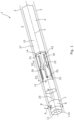
- Fig. 1 shows a perforation tool system 1 for perforating a screen, a sliding sleeve or a casing wall of a casing 2 or another well tubular metal structure in a borehole 3.
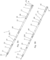
- the perforation tool system 1 comprises a first tool part 4 having an axial extension 5, which is also the axial extension of the perforation tool system 1, and at least one anchoring section 6, 6A, 6B, 6C (shown in Figs. 5A and 5B ) for anchoring the tool system 1 in the well when perforating, i.e., making openings in the screen, the sliding sleeve or the casing wall of a casing 2.
- the perforation tool system 1 further comprises a second tool part 7 adapted to rotate around the axial extension 5 and move axially in relation to the first tool part 4, the second tool part 7 comprising a machining bit 8 which is movable in a direction 9 radial to the axial extension in order to make the opening/perforation.
- the first tool part 4 is arranged closer to the top of the well than the second tool part 7.
- the perforation tool system 1 further comprises an axial actuator 10 comprised in the first tool part 4 and comprising a shaft 25 for axially moving the second tool part 7 in relation to the first tool part 4, a rotation unit 12 for rotating the second tool part 7 in relation to the first tool part 4, and a first actuator 11 comprising an electric motor 11A for rotating the bit 8.
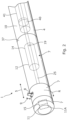
- the rotation unit 12 comprises a tubular sleeve 14 having a slot 18 engaging a pin 19 of the shaft 25, and the slot 18 comprises a first longitudinal slot part 18A, a second longitudinal slot part 18B (shown in Fig. 3 ) and a first guiding slot part 20 connecting the first and second longitudinal slot parts.
- the pin is fixedly fastened to the shaft.
- the bit 8 can drill a first opening, e.g. in the casing wall, in a first position P1.
- the second tool part 7 is rotated along a rotation direction R as the pin 19 on the shaft 25 moves in the slot 18 and as the sleeve 14 is fixedly fastened to the first tool part 4, and then the shaft 25 is forced to rotate, rotating the second tool part 7 and thus the bit 8.
- the bit 8 drills a second opening in the casing wall.
- the sleeve 14 rotates with the second tool part 7 and is fixedly fastened to the second tool part 7, and not to the first tool part.
- the shaft 25 does not rotate but merely moves back and forth along the axial extension 5.
- the bit 8 is a drill bit moving along the direction 9 radially and perpendicularly to the axial extension 5 in order to make the openings/perforations.
- the openings/perforations are drilled in, e.g., the casing wall with a mutual distance in the requested perforation pattern in order to provide a perforated zone without the use of explosives.
- the slot is made in a pattern matching the requested perforation pattern.
- the perforation tool system 1 is thus a mechanical perforation tool system, i.e., a system not using explosives.
- the perforation tool system 1 is powered through a wireline 22, i.e., the perforation tool system 1 is a perforation wireline tool system 1.
- the perforation tool system 1 comprises an electric motor 24 powered through the wireline 22 for driving a pump 25B.
- the perforation tool system 1 further comprises an electronic section 21 for controlling the operation of the perforation tool system.
- the perforation tool system 1 comprises a compensator 23 for providing overpressure inside the perforation tool system.
- the pump 25B drives the axial actuator 10 to move the shaft 25 back and forth along the axial extension 5.
- the shaft 25 of the axial actuator 10 is retracted, and in Fig. 5B the shaft 25 is in its projected position in which the bit 8 has been rotated to a new position to drill a new opening.
- the first longitudinal slot part 18A has a first part 51 and a second part 52, and a first guiding slot part 20, 20' is connected to the first longitudinal slot part 18A between the first part and the second part so that the pin 19 moving in the second longitudinal slot part 18B moves past another second guiding slot part 20, 20" into the intended first guiding slot part 20, 20' and further into the first longitudinal slot part 18A.
- the slot 18 comprises the second guiding slot part 20, 20" connecting the second longitudinal slot part 18B with another first longitudinal slot part 18A.
- the second longitudinal slot part 18B has a first part 53 and a second part 54, and the second guiding slot part 20, 20" is connected to the second longitudinal slot part 18B between the first part 53 and the second part 54.
- a corner 56 provided in the transition between the second part 52, 54 and the guiding slot part 20 forces and guides the pin 19 into the intended guiding slot part 20.
- the pin 19 enters the longitudinal slot part 18 from one side 57 and bumps against the opposing side 58 of the longitudinal slot part 18 and is guided further along the longitudinal slot part to the first part 51, 53.
- the pin 19 is in a first position P1 when the pin 19 is arranged in the first part 51 of the first longitudinal slot part 18A, and the pin 19 is in a second position P2 when the pin 19 is arranged in the first part 53 of the second longitudinal slot part 18B.
- the first longitudinal slot part 18A is displaced from the second longitudinal slot part 18B along a circumference of a tool housing 37 (shown in Fig. 1 ) and slightly overlapping the second longitudinal slot part along the axial extension 5.
- the guiding slot part 20 of the slot 18 further comprises a first inclined slot part 20A, a second inclined slot part 20B and an intermediate slot part 20C connecting the first inclined slot part 20A and the second inclined slot part 20B.
- the first inclined slot part 20A is connected to the first longitudinal slot part 18A
- the second inclined slot part 20B is connected to the second longitudinal slot part 18B.
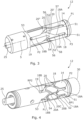
- the sleeve 14 of Fig. 4 has more positions than the sleeve 14 of Fig. 3 , as the sleeve 14 of Fig. 4 has reverse positions RP1, RP2 as well as the positions of the sleeve 14 of Fig. 3 .
- a control unit 30 for controlling the movement of the pin 19 in the slot 18 is arranged in connection with the sleeve 14 so as to force the sleeve 14 in one rotational direction to move the pin 19 between the "forward" positions and to force the sleeve 14 in the opposing rotational direction to move the pin 19 between the "reverse” positions.
- the control unit 30 is connected to the sleeve 14 of the rotation unit 12 for forcing the pin 19 towards one side of the slot 18 or forcing the pin 19 towards the opposing side of the slot 18. In this way, the perforation tool system 1 is able to drill more holes before the perforation tool system has to move position along the axial extension 5.
- the rotation unit 12 is disclosed without any cover but may have a cover for covering and protecting the slot 18 from the well fluid.
- the rotation unit 12 is comprised inside the tool housing 37, and the sleeve 14 surrounds the shaft 25 of the axial actuator 10.
- the axial actuator 10 comprises a hydraulic cylinder 41 and a reciprocating piston 40 connected to the shaft 25 for moving the shaft 25 and the pin 19 back and forth in the slot 18.
- the bit 8 is moved radially in relation to the axial extension 5 by means of an electric motor and/or hydraulics along the direction 9.
- the bit 8 is rotated by an electric motor 11A of the first actuator 11 so that the first actuator 11 comprises a gear 15 for changing a rotational speed of the electric motor 11A.
- bit 8 is moved radially in a bit housing/cylinder 31, the bit 8 having a sharp end 32 facing the casing 2 and a piston end of the piston 33, and the bit 8 being moved radially in relation to the axial extension by means of an electric motor driving a hydraulic cylinder which is in fluid communication with the bit housing 31 pressing onto the piston end.
- the bit 8 is moved radially by means of a hydraulic cylinder 31, and thereby the weight on bit (WOB) can be held more constant than when using a motor.
- the bit 8 forms a piston 33 of the hydraulic cylinder 31.
- the hydraulic cylinder 31 comprises a spring 34 arranged between a bottom of the cylinder 31 and the piston 33 so that the piston is retracted when pressurised fluid is not pressing the piston 33 outwards.
- the spring 34 is squeezed between the piston 33 and a flange 81 of the cylinder housing 31 when the piston and the bit 8 are pressed outwards in the projected position of the bit.
- the spring 34 acts as a failsafe mechanism as the spring 34 retracts the bit 8 when the power to the tool is switched off, and the system can be retracted from the well.
- the piston 33 forms part of a gear 15 that engages another gear 15 of the shaft 25.
- the bit 8 is rotated by an electric motor 11A of the first actuator 11 so that the first actuator 11 comprises the gear 15 for changing a rotational speed of the electric motor 11A, which gear engages with the piston housing 31 engaging the bit 8 via a key in a keyway connection.
- the gear 15 is a bevel gear, but it may also be a planetary gear.
- the system comprises a first anchoring section 6, 6A and a second anchoring section 6, 6B, and the anchoring sections are arranged with a mutual axial distance between them, both anchoring sections being arranged closer to the top of the well than the second tool part 7 and the bit 8.
- the system comprises a third anchoring section 6, 6C which is axially movable in relation to the other anchoring sections.
- the anchoring sections furthermore have the function of displacing the whole tool string/tool system 1 in relation to the casing wall so that the bit 8 is brought into contact with the inner face of the casing 2 before the bit 8 starts drilling and moving radially along the direction 9.
- the system may further comprise a pinching or cutting tool 78 projectable through an opening in the casing 2 provided by the machining bit 8 for cutting a control line outside the casing 2.
- the perforation tool system 1 may also comprise a fluid cleaner for cleaning up cuttings from the machining process and a driving unit, such as a downhole tractor.
- Perforations are normally made in a predetermined pattern in order to optimise the inflow of well fluid.
- the perforation tool system 1 is arranged in the casing 2 opposite a section to be perforated, and then a first opening is drilled in the casing 2 by rotating the machining bit 8 and moving the machining bit 8 in the direction 9 radial to the axial extension for contacting an inner face of the casing 2.
- the bit 8 is retracted, and the axial actuator 10 is activated to move the shaft 25 and the pin 19 in a first direction along the slot 18 from the first position P1 to the second position P2, where a second opening is drilled in the casing 2 by rotating the machining bit 8 and moving the machining bit 8 in the direction 9 radial to the axial extension for contacting an inner face of the casing 2, and then the bit 8 is retracted again.
- the axial actuator 10 is activated to move the shaft 25 and the pin 19 in a second direction opposite the first direction along the slot 18 from the second position P2 to the third position P3, a third opening is drilled in the casing 2 by rotating the machining bit 8 and moving the machining bit 8 in the direction 9 radial to the axial extension 5 for contacting an inner face of the casing 2, the bit 8 is retracted, and this process is repeated until the openings are made.
- the perforation tool system 1 is moved to a new position along the axial extension 5, and the process is repeated. In this way, several metres of perforated zone/section can be made in a predetermined pattern without the use of explosives as in the known perforation guns.
- An axial actuator may be called a stroking tool, being a tool providing an axial force.
- the axial actuator/stroking tool comprises an electric motor for driving a pump.
- the pump pumps fluid into a piston housing/cylinder 41 to move a reciprocating piston 40 acting therein.
- the piston 40 is arranged on the stroker shaft 25.
- the pump may pump fluid out of the piston housing/cylinder 41 on one side and simultaneously suck fluid in on the other side of the piston 40.
- fluid or "well fluid” is meant any kind of fluid that may be present in oil or gas wells downhole, such as natural gas, oil, oil mud, crude oil, water, etc.
- gas is meant any kind of gas composition present in a well, completion or open hole, and by “oil” is meant any kind of oil composition, such as crude oil, an oil-containing fluid, etc.
- Oil and water fluids may thus all comprise other elements or substances than gas, oil and/or water, respectively.
- casing or “well tubular metal structure” is meant any kind of pipe, tubing, tubular, liner, string, etc., used downhole in relation to oil or natural gas production.
- a downhole tractor can be used to push the tool all the way into position in the well.
- the downhole tractor may have projectable arms having wheels, wherein the wheels contact the inner surface of the casing for propelling the tractor and the tool forward in the casing.
- a downhole tractor is any kind of driving tool capable of pushing or pulling tools in a well downhole, such as a Well Tractor ® .
Landscapes
- Geology (AREA)
- Life Sciences & Earth Sciences (AREA)
- Engineering & Computer Science (AREA)
- Mining & Mineral Resources (AREA)
- Environmental & Geological Engineering (AREA)
- Fluid Mechanics (AREA)
- Physics & Mathematics (AREA)
- General Life Sciences & Earth Sciences (AREA)
- Geochemistry & Mineralogy (AREA)
- Processing Of Stones Or Stones Resemblance Materials (AREA)
- Perforating, Stamping-Out Or Severing By Means Other Than Cutting (AREA)
- Drilling Tools (AREA)
- Earth Drilling (AREA)
Claims (10)
- Système d'outil de perforation (1) pour perforer un écran, un manchon coulissant ou une paroi de tubage d'un tubage (2) dans un trou de forage (3) ayant un sommet, comprenant :- une première partie d'outil (4) ayant une extension axiale (5) et une section d'ancrage (6, 6A, 6B, 6C),- une deuxième partie d'outil (7) adaptée pour tourner et se déplacer axialement par rapport à la première partie d'outil, la deuxième partie d'outil comprenant un trépan d'usinage (8) qui est mobile dans une direction (9) radiale par rapport à l'extension axiale,- un actionneur axial (10) compris dans la première partie d'outil et comprenant un arbre (25) pour déplacer axialement la deuxième partie d'outil par rapport à la première partie d'outil,- une unité de rotation (12) pour faire tourner la deuxième partie d'outil par rapport à la première partie d'outil, et- un premier actionneur (11) comprenant un moteur électrique (11A) pour faire tourner le trépan, caractérisé en ce quel'unité de rotation comprend un manchon (14) ayant une fente (18) en prise avec une broche (19) de l'arbre, la fente comprenant une première partie de fente longitudinale (18A), une deuxième partie de fente longitudinale (18B) et une première partie de fente de guidage (20, 20') reliant les première et deuxième parties de fente longitudinale.
- Système d'outil de perforation (1) selon la revendication 1, dans lequel la première partie de fente longitudinale (18A) a une première partie (51) et une deuxième partie (52), la première partie de fente de guidage (20, 20') étant reliée à la première partie de fente longitudinale (18A) entre la première partie et la deuxième partie.
- Système d'outil de perforation (1) selon la revendication 2, dans lequel la deuxième partie de fente longitudinale (18B) a une première partie (53) et une deuxième partie (54), la partie de fente de guidage (20) étant reliée à la deuxième partie de fente longitudinale (18B) entre la première partie (53) et la deuxième partie (54).
- Système d'outil de perforation (1) selon la revendication 3, dans lequel la broche (19) est dans une première position lorsque la broche est disposée dans la première partie (51) de la première partie de fente longitudinale (18A), et la broche est dans une deuxième position lorsque la broche est disposée dans la première partie (53) de la deuxième partie de fente longitudinale (18B).
- Système d'outil de perforation (1) selon l'une quelconque des revendications précédentes, dans lequel la première partie de fente longitudinale (18A) est déplacée de la deuxième partie de fente longitudinale (18B) le long d'une circonférence d'un boîtier d'outil (37).
- Système d'outil de perforation (1) selon l'une quelconque des revendications précédentes, dans lequel la fente comprend une deuxième partie de fente de guidage (20, 20") reliant la deuxième partie de fente longitudinale (18B) à une autre première partie de fente longitudinale (18A).
- Système d'outil de perforation (1) selon l'une quelconque des revendications précédentes, dans lequel la partie de fente de guidage comprend en outre une première partie de fente inclinée (20A), une deuxième partie de fente inclinée (20B) et une partie de fente intermédiaire (20C) reliant la première partie de fente inclinée et la deuxième partie de fente inclinée.
- Système d'outil de perforation (1) selon la revendication 7, dans lequel la première partie de fente inclinée (20A) est reliée à la première partie de fente longitudinale (18A), et la deuxième partie de fente inclinée (20B) est reliée à la deuxième partie de fente longitudinale (18B).
- Système d'outil de perforation (1) selon l'une quelconque des revendications précédentes, comprenant en outre une unité d'entraînement, telle qu'un tracteur de fond de trou.
- Procédé de perforation comprenant les étapes consistant à :- disposer le système d'outil de perforation selon l'une quelconque des revendications précédentes dans un tubage opposé à la section à perforer,- percer une première ouverture dans le tubage en faisant tourner le trépan d'usinage (8) et en déplaçant le trépan d'usinage (8) dans la direction (9) radiale à l'extension axiale pour entrer en contact avec une face intérieure du tubage,- rétracter le trépan,- activer l'actionneur axial pour déplacer l'arbre et la broche dans une première direction le long de la fente, d'une première position (P1) à une deuxième position (P2),- percer une deuxième ouverture dans le tubage en faisant tourner le trépan d'usinage (8) et en déplaçant le trépan d'usinage (8) dans la direction (9) radiale à l'extension axiale pour entrer en contact avec une face intérieure du tubage, et- rétracter le trépan.
Applications Claiming Priority (2)
| Application Number | Priority Date | Filing Date | Title |
|---|---|---|---|
| DKPA202100465A DK181330B1 (en) | 2021-05-05 | 2021-05-05 | Mechanical perforation tool system |
| PCT/EP2022/061974 WO2022233933A1 (fr) | 2021-05-05 | 2022-05-04 | Système d'outil de perforation mécanique |
Publications (2)
| Publication Number | Publication Date |
|---|---|
| EP4334568A1 EP4334568A1 (fr) | 2024-03-13 |
| EP4334568B1 true EP4334568B1 (fr) | 2025-06-18 |
Family
ID=76503820
Family Applications (1)
| Application Number | Title | Priority Date | Filing Date |
|---|---|---|---|
| EP22727831.4A Active EP4334568B1 (fr) | 2021-05-05 | 2022-05-04 | Système d'outil de perforation mécanique |
Country Status (4)
| Country | Link |
|---|---|
| EP (1) | EP4334568B1 (fr) |
| DK (1) | DK181330B1 (fr) |
| NO (1) | NO20220513A1 (fr) |
| WO (1) | WO2022233933A1 (fr) |
Families Citing this family (2)
| Publication number | Priority date | Publication date | Assignee | Title |
|---|---|---|---|---|
| CN117418812A (zh) * | 2023-11-24 | 2024-01-19 | 西南石油大学 | 一种可定位机械射孔工具 |
| NO20240442A1 (en) * | 2024-05-07 | 2025-11-10 | Altus Intervention Tech As | A method and a system for drilling a radial hole in a tubular structure |
Family Cites Families (3)
| Publication number | Priority date | Publication date | Assignee | Title |
|---|---|---|---|---|
| US2998068A (en) * | 1958-12-15 | 1961-08-29 | Jersey Prod Res Co | Apparatus for use in wells |
| US7562700B2 (en) * | 2006-12-08 | 2009-07-21 | Baker Hughes Incorporated | Wireline supported tubular mill |
| EP2813665A1 (fr) * | 2013-06-14 | 2014-12-17 | Welltec A/S | Système et procédé d'usinage de fond de trou |
-
2021
- 2021-05-05 DK DKPA202100465A patent/DK181330B1/en active IP Right Grant
-
2022
- 2022-05-04 WO PCT/EP2022/061974 patent/WO2022233933A1/fr not_active Ceased
- 2022-05-04 EP EP22727831.4A patent/EP4334568B1/fr active Active
- 2022-05-04 NO NO20220513A patent/NO20220513A1/en unknown
Also Published As
| Publication number | Publication date |
|---|---|
| WO2022233933A1 (fr) | 2022-11-10 |
| EP4334568A1 (fr) | 2024-03-13 |
| DK181330B1 (en) | 2023-08-16 |
| NO20220513A1 (en) | 2022-11-07 |
| DK202100465A1 (en) | 2021-06-22 |
Similar Documents
| Publication | Publication Date | Title |
|---|---|---|
| EP3008277B1 (fr) | Système et procédé d'usinage de fond de trou | |
| CA2655149C (fr) | Ensemble de forage de fond de trou et procede d'utilisation de celui-ci | |
| CA2238782C (fr) | Methode et appareil pour le percage du cuvelage et le forage du sol environnant | |
| EP2499322B1 (fr) | Tracteur de fond de trou | |
| US5392858A (en) | Milling apparatus and method for well casing | |
| US6705413B1 (en) | Drilling with casing | |
| EP2530238B1 (fr) | Outil de découpe de tubage de fond de puits | |
| CA2931422C (fr) | Outil de nettoyage d'obstruction de trou de forage forable et reinitialisable | |
| CA2401813C (fr) | Dispositif et methode combines d'extension de tubage/de tubage pendant le forage | |
| EP4334568B1 (fr) | Système d'outil de perforation mécanique | |
| RU2109931C1 (ru) | Перфоратор механический для сверления стенок скважины, обсаженной трубами (варианты) | |
| EP4194662A1 (fr) | Outil de câble de fond de trou | |
| US12312886B2 (en) | Downhole tool string | |
| EP3891355B1 (fr) | Outil de fond de trou comportant une longue rallonge en saillie | |
| US12203369B2 (en) | Modified whipstock design integrating smart cleanout mechanisms |
Legal Events
| Date | Code | Title | Description |
|---|---|---|---|
| STAA | Information on the status of an ep patent application or granted ep patent |
Free format text: STATUS: UNKNOWN |
|
| STAA | Information on the status of an ep patent application or granted ep patent |
Free format text: STATUS: THE INTERNATIONAL PUBLICATION HAS BEEN MADE |
|
| PUAI | Public reference made under article 153(3) epc to a published international application that has entered the european phase |
Free format text: ORIGINAL CODE: 0009012 |
|
| STAA | Information on the status of an ep patent application or granted ep patent |
Free format text: STATUS: REQUEST FOR EXAMINATION WAS MADE |
|
| 17P | Request for examination filed |
Effective date: 20231128 |
|
| AK | Designated contracting states |
Kind code of ref document: A1 Designated state(s): AL AT BE BG CH CY CZ DE DK EE ES FI FR GB GR HR HU IE IS IT LI LT LU LV MC MK MT NL NO PL PT RO RS SE SI SK SM TR |
|
| DAV | Request for validation of the european patent (deleted) | ||
| DAX | Request for extension of the european patent (deleted) | ||
| GRAP | Despatch of communication of intention to grant a patent |
Free format text: ORIGINAL CODE: EPIDOSNIGR1 |
|
| STAA | Information on the status of an ep patent application or granted ep patent |
Free format text: STATUS: GRANT OF PATENT IS INTENDED |
|
| INTG | Intention to grant announced |
Effective date: 20240920 |
|
| GRAJ | Information related to disapproval of communication of intention to grant by the applicant or resumption of examination proceedings by the epo deleted |
Free format text: ORIGINAL CODE: EPIDOSDIGR1 |
|
| STAA | Information on the status of an ep patent application or granted ep patent |
Free format text: STATUS: REQUEST FOR EXAMINATION WAS MADE |
|
| GRAS | Grant fee paid |
Free format text: ORIGINAL CODE: EPIDOSNIGR3 |
|
| STAA | Information on the status of an ep patent application or granted ep patent |
Free format text: STATUS: GRANT OF PATENT IS INTENDED |
|
| GRAP | Despatch of communication of intention to grant a patent |
Free format text: ORIGINAL CODE: EPIDOSNIGR1 |
|
| INTC | Intention to grant announced (deleted) | ||
| INTG | Intention to grant announced |
Effective date: 20250114 |
|
| GRAA | (expected) grant |
Free format text: ORIGINAL CODE: 0009210 |
|
| STAA | Information on the status of an ep patent application or granted ep patent |
Free format text: STATUS: THE PATENT HAS BEEN GRANTED |
|
| AK | Designated contracting states |
Kind code of ref document: B1 Designated state(s): AL AT BE BG CH CY CZ DE DK EE ES FI FR GB GR HR HU IE IS IT LI LT LU LV MC MK MT NL NO PL PT RO RS SE SI SK SM TR |
|
| REG | Reference to a national code |
Ref country code: GB Ref legal event code: FG4D |
|
| REG | Reference to a national code |
Ref country code: CH Ref legal event code: EP |
|
| REG | Reference to a national code |
Ref country code: DE Ref legal event code: R096 Ref document number: 602022016118 Country of ref document: DE |
|
| REG | Reference to a national code |
Ref country code: CH Ref legal event code: EP |
|
| REG | Reference to a national code |
Ref country code: IE Ref legal event code: FG4D |
|
| PG25 | Lapsed in a contracting state [announced via postgrant information from national office to epo] |
Ref country code: FI Free format text: LAPSE BECAUSE OF FAILURE TO SUBMIT A TRANSLATION OF THE DESCRIPTION OR TO PAY THE FEE WITHIN THE PRESCRIBED TIME-LIMIT Effective date: 20250618 |
|
| REG | Reference to a national code |
Ref country code: LT Ref legal event code: MG9D |
|
| PG25 | Lapsed in a contracting state [announced via postgrant information from national office to epo] |
Ref country code: GR Free format text: LAPSE BECAUSE OF FAILURE TO SUBMIT A TRANSLATION OF THE DESCRIPTION OR TO PAY THE FEE WITHIN THE PRESCRIBED TIME-LIMIT Effective date: 20250919 |
|
| P01 | Opt-out of the competence of the unified patent court (upc) registered |
Free format text: CASE NUMBER: UPC_APP_6503_4334568/2025 Effective date: 20250910 |
|
| PG25 | Lapsed in a contracting state [announced via postgrant information from national office to epo] |
Ref country code: BG Free format text: LAPSE BECAUSE OF FAILURE TO SUBMIT A TRANSLATION OF THE DESCRIPTION OR TO PAY THE FEE WITHIN THE PRESCRIBED TIME-LIMIT Effective date: 20250618 |
|
| PG25 | Lapsed in a contracting state [announced via postgrant information from national office to epo] |
Ref country code: HR Free format text: LAPSE BECAUSE OF FAILURE TO SUBMIT A TRANSLATION OF THE DESCRIPTION OR TO PAY THE FEE WITHIN THE PRESCRIBED TIME-LIMIT Effective date: 20250618 |
|
| PG25 | Lapsed in a contracting state [announced via postgrant information from national office to epo] |
Ref country code: RS Free format text: LAPSE BECAUSE OF FAILURE TO SUBMIT A TRANSLATION OF THE DESCRIPTION OR TO PAY THE FEE WITHIN THE PRESCRIBED TIME-LIMIT Effective date: 20250918 |
|
| REG | Reference to a national code |
Ref country code: NL Ref legal event code: MP Effective date: 20250618 |
|
| PG25 | Lapsed in a contracting state [announced via postgrant information from national office to epo] |
Ref country code: LV Free format text: LAPSE BECAUSE OF FAILURE TO SUBMIT A TRANSLATION OF THE DESCRIPTION OR TO PAY THE FEE WITHIN THE PRESCRIBED TIME-LIMIT Effective date: 20250618 |
|
| PG25 | Lapsed in a contracting state [announced via postgrant information from national office to epo] |
Ref country code: NL Free format text: LAPSE BECAUSE OF FAILURE TO SUBMIT A TRANSLATION OF THE DESCRIPTION OR TO PAY THE FEE WITHIN THE PRESCRIBED TIME-LIMIT Effective date: 20250618 |
|
| PG25 | Lapsed in a contracting state [announced via postgrant information from national office to epo] |
Ref country code: PT Free format text: LAPSE BECAUSE OF FAILURE TO SUBMIT A TRANSLATION OF THE DESCRIPTION OR TO PAY THE FEE WITHIN THE PRESCRIBED TIME-LIMIT Effective date: 20251020 |
|
| REG | Reference to a national code |
Ref country code: AT Ref legal event code: MK05 Ref document number: 1804337 Country of ref document: AT Kind code of ref document: T Effective date: 20250618 |
|
| PG25 | Lapsed in a contracting state [announced via postgrant information from national office to epo] |
Ref country code: IS Free format text: LAPSE BECAUSE OF FAILURE TO SUBMIT A TRANSLATION OF THE DESCRIPTION OR TO PAY THE FEE WITHIN THE PRESCRIBED TIME-LIMIT Effective date: 20251018 |
|
| PG25 | Lapsed in a contracting state [announced via postgrant information from national office to epo] |
Ref country code: AT Free format text: LAPSE BECAUSE OF FAILURE TO SUBMIT A TRANSLATION OF THE DESCRIPTION OR TO PAY THE FEE WITHIN THE PRESCRIBED TIME-LIMIT Effective date: 20250618 Ref country code: SM Free format text: LAPSE BECAUSE OF FAILURE TO SUBMIT A TRANSLATION OF THE DESCRIPTION OR TO PAY THE FEE WITHIN THE PRESCRIBED TIME-LIMIT Effective date: 20250618 |
|
| PG25 | Lapsed in a contracting state [announced via postgrant information from national office to epo] |
Ref country code: CZ Free format text: LAPSE BECAUSE OF FAILURE TO SUBMIT A TRANSLATION OF THE DESCRIPTION OR TO PAY THE FEE WITHIN THE PRESCRIBED TIME-LIMIT Effective date: 20250618 |
|
| PG25 | Lapsed in a contracting state [announced via postgrant information from national office to epo] |
Ref country code: PL Free format text: LAPSE BECAUSE OF FAILURE TO SUBMIT A TRANSLATION OF THE DESCRIPTION OR TO PAY THE FEE WITHIN THE PRESCRIBED TIME-LIMIT Effective date: 20250618 |
|
| PG25 | Lapsed in a contracting state [announced via postgrant information from national office to epo] |
Ref country code: EE Free format text: LAPSE BECAUSE OF FAILURE TO SUBMIT A TRANSLATION OF THE DESCRIPTION OR TO PAY THE FEE WITHIN THE PRESCRIBED TIME-LIMIT Effective date: 20250618 |
|
| PG25 | Lapsed in a contracting state [announced via postgrant information from national office to epo] |
Ref country code: SK Free format text: LAPSE BECAUSE OF FAILURE TO SUBMIT A TRANSLATION OF THE DESCRIPTION OR TO PAY THE FEE WITHIN THE PRESCRIBED TIME-LIMIT Effective date: 20250618 |
|
| PG25 | Lapsed in a contracting state [announced via postgrant information from national office to epo] |
Ref country code: ES Free format text: LAPSE BECAUSE OF FAILURE TO SUBMIT A TRANSLATION OF THE DESCRIPTION OR TO PAY THE FEE WITHIN THE PRESCRIBED TIME-LIMIT Effective date: 20250618 |
|
| PG25 | Lapsed in a contracting state [announced via postgrant information from national office to epo] |
Ref country code: DK Free format text: LAPSE BECAUSE OF FAILURE TO SUBMIT A TRANSLATION OF THE DESCRIPTION OR TO PAY THE FEE WITHIN THE PRESCRIBED TIME-LIMIT Effective date: 20250618 |
|
| PG25 | Lapsed in a contracting state [announced via postgrant information from national office to epo] |
Ref country code: IT Free format text: LAPSE BECAUSE OF FAILURE TO SUBMIT A TRANSLATION OF THE DESCRIPTION OR TO PAY THE FEE WITHIN THE PRESCRIBED TIME-LIMIT Effective date: 20250618 |
|
| PLBE | No opposition filed within time limit |
Free format text: ORIGINAL CODE: 0009261 |
|
| STAA | Information on the status of an ep patent application or granted ep patent |
Free format text: STATUS: NO OPPOSITION FILED WITHIN TIME LIMIT |
|
| REG | Reference to a national code |
Ref country code: CH Ref legal event code: L10 Free format text: ST27 STATUS EVENT CODE: U-0-0-L10-L00 (AS PROVIDED BY THE NATIONAL OFFICE) Effective date: 20260430 |