EP4334582B1 - Verfahren zur steuerung einer turbomaschine mit mindestens einer elektrischen maschine und zugehöriges steuerungssystem - Google Patents
Verfahren zur steuerung einer turbomaschine mit mindestens einer elektrischen maschine und zugehöriges steuerungssystem Download PDFInfo
- Publication number
- EP4334582B1 EP4334582B1 EP22724819.2A EP22724819A EP4334582B1 EP 4334582 B1 EP4334582 B1 EP 4334582B1 EP 22724819 A EP22724819 A EP 22724819A EP 4334582 B1 EP4334582 B1 EP 4334582B1
- Authority
- EP
- European Patent Office
- Prior art keywords
- turbomachine
- command
- variation
- mod
- control
- Prior art date
- Legal status (The legal status is an assumption and is not a legal conclusion. Google has not performed a legal analysis and makes no representation as to the accuracy of the status listed.)
- Active
Links
Images



Classifications
-
- F—MECHANICAL ENGINEERING; LIGHTING; HEATING; WEAPONS; BLASTING
- F02—COMBUSTION ENGINES; HOT-GAS OR COMBUSTION-PRODUCT ENGINE PLANTS
- F02C—GAS-TURBINE PLANTS; AIR INTAKES FOR JET-PROPULSION PLANTS; CONTROLLING FUEL SUPPLY IN AIR-BREATHING JET-PROPULSION PLANTS
- F02C9/00—Controlling gas-turbine plants; Controlling fuel supply in air- breathing jet-propulsion plants
- F02C9/48—Control of fuel supply conjointly with another control of the plant
-
- F—MECHANICAL ENGINEERING; LIGHTING; HEATING; WEAPONS; BLASTING
- F02—COMBUSTION ENGINES; HOT-GAS OR COMBUSTION-PRODUCT ENGINE PLANTS
- F02C—GAS-TURBINE PLANTS; AIR INTAKES FOR JET-PROPULSION PLANTS; CONTROLLING FUEL SUPPLY IN AIR-BREATHING JET-PROPULSION PLANTS
- F02C3/00—Gas-turbine plants characterised by the use of combustion products as the working fluid
- F02C3/04—Gas-turbine plants characterised by the use of combustion products as the working fluid having a turbine driving a compressor
- F02C3/107—Gas-turbine plants characterised by the use of combustion products as the working fluid having a turbine driving a compressor with two or more rotors connected by power transmission
- F02C3/113—Gas-turbine plants characterised by the use of combustion products as the working fluid having a turbine driving a compressor with two or more rotors connected by power transmission with variable power transmission between rotors
-
- F—MECHANICAL ENGINEERING; LIGHTING; HEATING; WEAPONS; BLASTING
- F02—COMBUSTION ENGINES; HOT-GAS OR COMBUSTION-PRODUCT ENGINE PLANTS
- F02C—GAS-TURBINE PLANTS; AIR INTAKES FOR JET-PROPULSION PLANTS; CONTROLLING FUEL SUPPLY IN AIR-BREATHING JET-PROPULSION PLANTS
- F02C9/00—Controlling gas-turbine plants; Controlling fuel supply in air- breathing jet-propulsion plants
- F02C9/48—Control of fuel supply conjointly with another control of the plant
- F02C9/56—Control of fuel supply conjointly with another control of the plant with power transmission control
-
- F—MECHANICAL ENGINEERING; LIGHTING; HEATING; WEAPONS; BLASTING
- F05—INDEXING SCHEMES RELATING TO ENGINES OR PUMPS IN VARIOUS SUBCLASSES OF CLASSES F01-F04
- F05D—INDEXING SCHEME FOR ASPECTS RELATING TO NON-POSITIVE-DISPLACEMENT MACHINES OR ENGINES, GAS-TURBINES OR JET-PROPULSION PLANTS
- F05D2220/00—Application
- F05D2220/30—Application in turbines
- F05D2220/32—Application in turbines in gas turbines
- F05D2220/323—Application in turbines in gas turbines for aircraft propulsion, e.g. jet engines
-
- F—MECHANICAL ENGINEERING; LIGHTING; HEATING; WEAPONS; BLASTING
- F05—INDEXING SCHEMES RELATING TO ENGINES OR PUMPS IN VARIOUS SUBCLASSES OF CLASSES F01-F04
- F05D—INDEXING SCHEME FOR ASPECTS RELATING TO NON-POSITIVE-DISPLACEMENT MACHINES OR ENGINES, GAS-TURBINES OR JET-PROPULSION PLANTS
- F05D2220/00—Application
- F05D2220/70—Application in combination with
- F05D2220/76—Application in combination with an electrical generator
-
- F—MECHANICAL ENGINEERING; LIGHTING; HEATING; WEAPONS; BLASTING
- F05—INDEXING SCHEMES RELATING TO ENGINES OR PUMPS IN VARIOUS SUBCLASSES OF CLASSES F01-F04
- F05D—INDEXING SCHEME FOR ASPECTS RELATING TO NON-POSITIVE-DISPLACEMENT MACHINES OR ENGINES, GAS-TURBINES OR JET-PROPULSION PLANTS
- F05D2270/00—Control
- F05D2270/01—Purpose of the control system
- F05D2270/05—Purpose of the control system to affect the output of the engine
Definitions
- the present invention belongs to the general field of controlling the operation of turbomachines. It relates more particularly to a method for controlling a turbomachine equipped with a gas turbine and also comprising at least one electrical machine forming a power injection/collection device on a rotation shaft (low pressure or high pressure) of said gas generator. It also relates to a control system configured to implement said control method. Furthermore, the invention finds a particularly advantageous, although in no way limiting, application in the field of aeronautics, more particularly in the context of controlling a turbomachine equipping an aircraft.
- a turbomachine 100 comprising a gas generator is schematically represented. More particularly, the example of the figure 1 illustrates a turbomachine 100 of the double-flow, double-body turbojet type for aircraft.
- the turbomachine 100 comprises, from upstream to downstream in the direction of gas flow, a fan 110, a low-pressure compressor 111, a high-pressure compressor 112, a combustion chamber 113 which receives a fuel flow control Wf, a high-pressure turbine 114, a low-pressure turbine 115 and a primary exhaust nozzle 116.
- the low-pressure (or LP) compressor 111 and the low-pressure turbine 115 are connected by a low-pressure shaft 121 and together form a low-pressure body.
- the high-pressure (or HP) compressor 112 and the high-pressure turbine 114 are connected by a high-pressure shaft 122 and together form, with the combustion chamber, a high-pressure body.
- the fan 110 which is driven by the LP shaft 121, compresses the ingested air. This air is divided downstream of the fan 110 between a secondary air flow which is directed directly towards a secondary nozzle (not shown) through which it is ejected to participate in the thrust provided by the turbomachine 100, and a so-called primary flow which enters the gas generator, consisting of the low pressure body and the high pressure body, then which is ejected into the primary nozzle 116.
- the fuel flow control Wf is determined as a function of a difference between the current speed of the turbomachine and a setpoint that depends on a position of a control lever that can be manipulated by the pilot.
- a fuel control loop is implemented by a control device, generally integrated into the calculator of the full authority control device, also called "FADEC” (acronym from the Anglo-Saxon expression “Full Authority Digital Engine Control”), equipping the turbomachine.
- FADEC full authority control device
- the designer of a turbomachine must therefore try to optimize the placement of the operating line by placing it as high as possible, so as to benefit from better efficiencies for its compressors, while keeping a sufficient distance (i.e. a margin) from the operability stops, so as to allow safe accelerations/decelerations.
- turbomachine 100 in order to improve the operation of a turbomachine during transient phases, while limiting the impact of the design constraints linked to the operability stops, it has notably been proposed to hybridize the turbomachine 100 by equipping it with one or more electric machines (not shown in the figure 1 ).
- electric machines are configured to inject and/or draw power (or, equivalently, torque) from the rotating shafts.
- improving the operation of a turbomachine, via said electric machines also contributes to reducing the environmental footprint of the aircraft (i.e. the energy efficiency is improved).
- the document WO2016/020618 describes an implementation in which one or more electric machines are used. However, this implementation remains imprecise as to the manner in which the electric machines are controlled. In particular, no explicit and reproducible strategy for controlling the electric machines is proposed to optimize the operation and operability of the turbomachine.
- the document FR3087491 A1 also discloses a method of controlling a turbomachine according to the prior art.
- the present invention aims to overcome all or part of the drawbacks of the prior art, in particular those set out above, by proposing a solution that makes it possible to control a turbomachine equipped with a gas generator and comprising at least one electric machine more efficiently than the solutions of the prior art.
- a solution that makes it possible to control a turbomachine equipped with a gas generator and comprising at least one electric machine more efficiently than the solutions of the prior art.
- “more efficient” reference is made here to a solution whose implementation complexity is contained and which makes it possible to exploit the control redundancy provided by one or more electric machines to optimally meet the propulsion needs as well as the power injection/extraction needs, so as to guarantee the controllability as well as the operability of the turbomachine while respecting the operating limits thereof.
- said variations dU and dPelec are first determined.
- the determination of the variation dU aims to ensure the propulsion requirement of the turbomachine. It is therefore a question here of control in terms of total mechanical power, for the shaft(s) concerned at the time when said variation dU is determined.
- the determination of the dPelec variation aims to ensure the need for power injection/extraction by the electrical machine(s).
- the injection/extraction setpoint reflects a need for the overall energy management of the aircraft. It is therefore a total electrical power setpoint to be exchanged between the turbomachine and the aircraft's electrical network, so as to ensure the energy management of the turbomachine.
- control method according to the invention nevertheless differs from the prior art in that it proposes to control the turbomachine by determining a command which synthesizes the mechanical power requirements for the engine speed (variation dU) as well as the electrical power requirements for the operation of the electrical machine(s) (variation dPelec), so as to ensure the overall energy management of the turbomachine.
- the control method according to the invention advantageously proposes to rely on said variations dU and dPelec in order to determine an optimal multivariable control aimed at respecting the monitoring of these variations as well as the operating limits of the turbomachine.
- the multivariable control therefore corresponds to the solution of an optimization problem under constraints.
- This method of proceeding is particularly advantageous in that it allows the propulsion requirements to be met in a unified manner, as well as the injection/collection requirements, whether in stabilized mode or in transient mode, and within the operability limits of the turbomachine.
- control method may further comprise one or more of the following characteristics, taken in isolation or in all technically possible combinations.
- the steps included in the control loop further comprise a step of determining a monovariable fuel flow rate control as a function of said variation dU, operating limits of the turbomachine as well as current injection/collection values for said set of electrical machines, the single fuel flow rate control intended to be executed for the control of the turbomachine, among said monovariable control and the fuel flow component of the multivariable control, being said monovariable control.
- Said monovariable control offers the possibility of calculating, while respecting the operating limits of the turbomachine and independently of coordination with control means specifically dedicated to the electric machine(s), the variation in fuel flow rate necessary to satisfy the control need in terms of propulsion, while taking into account (for example by pre-compensating) the current (i.e. instantaneous) injection/collection variations obtained from measurements carried out on the turbomachine.
- the monovariable control takes precedence (i.e. it has priority) over the fuel flow component of the multivariable control.
- Such provisions make it possible to ensure tolerance for possible failures on the electrical chains (uncontrolled variations in injections/power draws, electrical network that fails to meet the needs defined by the commands determined for the electrical machines, delay in the application of said commands once they have been transmitted to control means dedicated to said electrical machines, etc.), or poor coordination between the control of the fuel flow and the control of the electrical machines.
- the turbomachine comprises a first electric machine forming a power injection/extraction device on the low-pressure rotation shaft and a second electric machine forming a power injection/extraction device on the high-pressure rotation shaft.
- the matrix V whose components v1 and v2 are given, makes it possible to deviate from the control objectives when their achievement is no longer possible under the constraint of monitoring the variations dU and dPelec, while respecting the operating limits of the turbomachine.
- the Q1 matrix is a weight matrix which makes it possible to minimise the variations of the control variables, and which can be chosen, for example, so as to favour the use of one control variable over another in the context of turbomachine control.
- the Q2 matrix for its part, is a weight matrix which makes it possible to minimize the deviation from the control objectives, and which can for example be chosen so as to favor one control objective over another.
- the Q2 matrix can be chosen so that the regulation of the engine speed is favored during transient phases with respect to electrical injections/sampling.
- said at least one shaft considered when determining the variation dU is the low-pressure rotation shaft if the control loop is implemented during a stabilized operating phase of the turbomachine, and the high-pressure rotation shaft if the control loop is implemented during a transient operating phase of the turbomachine.
- the invention relates to a computer program comprising instructions for implementing a control method according to the invention when said computer program is executed by a computer.
- This program may use any programming language, and may be in the form of source code, object code, or code intermediate between source code and object code, such as in a partially compiled form, or in any other desirable form.
- the invention relates to a computer-readable information or recording medium on which a computer program according to the invention is recorded.
- the information or recording medium may be any entity or device capable of storing the program.
- the medium may include a storage medium, such as a ROM, for example a CD ROM or a microelectronic circuit ROM, or a magnetic recording medium, for example a floppy disk or a hard disk.
- the information or recording medium may be a transmissible medium such as an electrical or optical signal, which may be conveyed via an electrical or optical cable, by radio or by other means.
- the program according to the invention may in particular be downloaded from a network such as the Internet.
- the information or recording medium may be an integrated circuit in which the program is incorporated, the circuit being adapted to execute or to be used in the execution of the method in question.
- said control system further comprises a fourth determination module configured to determine a monovariable fuel flow control as a function of said variation dU, operating limits of the turbomachine as well as current injection/collection values for said set of electrical machines, the single fuel flow control intended to be executed for the control of the turbomachine, among said monovariable control and the fuel flow component of the multivariable control, being said monovariable control.
- the invention relates to a turbomachine equipped with a gas generator comprising respectively low pressure and high pressure rotation shafts, the turbomachine comprising at least one electric machine forming a power injection/extraction device on at least one of said rotation shafts as well as a control system according to the invention.
- the invention relates to an aircraft comprising a turbomachine according to the invention.
- the present invention belongs to the field of control (i.e. regulation) of the operation of a turbomachine comprising a gas generator.
- turbomachine of the double-flow, double-spool turbojet type for aircraft such as a civil aircraft capable of transporting passengers
- the invention remains applicable regardless of the type of turbomachine considered, provided that the latter comprises a gas generator.
- turboshaft engine for example, it is possible to envisage a turboshaft engine, a turbofan, etc.
- the invention also remains applicable to any type of aircraft (airplane, helicopter, etc.), but also, more broadly, to any type of industrial machine equipped with a turbomachine according to the invention.
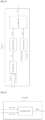
- FIG. 2 schematically represents, in its environment, an embodiment of a turbomachine T according to the invention.
- the turbomachine T admits a general structural configuration at least in accordance with the state of the art. As a non-limiting example, such a general configuration has been described above with reference to the figure 1 .
- the turbomachine T comprises, from upstream to downstream in the direction of gas flow, a fan 10, a low-pressure compressor 11, a high-pressure compressor 12, a combustion chamber 13 which receives a fuel flow control, a high-pressure turbine 14, a low-pressure turbine 15 and a primary exhaust nozzle 16.
- the low pressure (or LP) compressor 11 and the low pressure turbine 15 are connected by a low pressure shaft 21 and together form a low pressure body.
- the high pressure (or HP) compressor 12 and the high pressure turbine 14 are connected by a high pressure shaft 22 and together form, with the combustion chamber 13, a high pressure body.
- This air is divided downstream of the blower 10 between a secondary air flow which is directed directly towards a secondary nozzle (not shown) through which it is ejected to participate in the thrust provided by the turbomachine T, and a so-called primary flow which enters the gas generator, constituted by the low pressure body and the high pressure body, then which is ejected into the primary nozzle 16.
- turbomachine T As is known, the operation of the turbomachine T is controlled by a full authority regulation device, called “FADEC” 20.
- FADEC full authority regulation device
- the turbomachine T also comprises two electric machines, a first electric machine ME1 and a second electric machine ME2.
- each electric machine ME1, ME2 forms a power injection/collection device on one of said rotation shafts 21, 22. More particularly, it is considered here that the first electric machine ME1 (respectively the second electric machine ME2) is associated with the LP shaft 21 (respectively with the HP shaft 22).
- the power injected/collection by each electric machine ME1, ME2 on the shaft 21, 22 with which it cooperates is generated by said electric machine ME1, ME2 upon receipt of a power command, as is also detailed later.
- the invention is not limited to the case where two electrical machines are used to inject/draw power from the two shafts BP 21 and HP 22. Thus, nothing excludes, for example, envisaging other embodiments in which only one electrical machine is used, this single electrical machine being able to cooperate indifferently with the shaft BP 21 exclusively or with the shaft HP 22 exclusively.
- each electric machine ME1, ME2 can be configured according to a first operating mode, so as to generate power capable of driving the shaft associated with it.
- a first operating mode is conventionally called “motor operating mode”.
- Each electric machine ME1, ME2 can also be configured according to a second operating mode, so as to generate power capable of drawing mechanical energy from the shaft associated with it, this drawn energy being able for example to be used for the purposes of powering non-propulsion systems such as for example the air conditioning or defrosting system of the turbomachine T, or even also battery charging.
- a second operating mode is conventionally called “generator operating mode”.
- each electrical machine can also be seen as a device for injecting/taking mechanical torque from the shaft with which it cooperates. Indeed, it is entirely equivalent to consider an injection/taking from a shaft in terms of power or torque, these two physical quantities being linked to each other via the rotation speed of the shaft in question, as is well known to those skilled in the art. Also, without this leading to confusion, the only physical quantity now considered in the remainder of the description concerning these aspects is power.
- the turbomachine T also comprises a control system SYS_C configured to carry out processing operations enabling coordinated control of the fuel flow rate in the combustion chamber 13 and the powers injected/taken by the electrical machines ME1, ME2, by implementing a control method according to the invention, described in detail below and the steps of which are included in a control loop of the turbomachine T.
- SYS_C configured to carry out processing operations enabling coordinated control of the fuel flow rate in the combustion chamber 13 and the powers injected/taken by the electrical machines ME1, ME2, by implementing a control method according to the invention, described in detail below and the steps of which are included in a control loop of the turbomachine T.
- said control system SYS_C is integrated into the FADEC 20, more particularly into the latter's computer.
- said control system SYS_C is integrated into the FADEC 20, more particularly into the latter's computer.
- no limitation is attached to the location of said control system SYS_C within the turbomachine T since the latter is able to implement the control method according to the invention, and thus make it possible to control the turbomachine T in a particularly efficient manner.
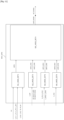
- FIG 3 schematically represents a first example of hardware architecture of the SYS_C control system belonging to the turbomachine of the figure 2 .
- control system SYS_C has the hardware architecture of a computer.
- said control system SYS_C comprises, in particular, a processor 1_1, a random access memory 2_1, a read only memory 3_1 and a non-volatile memory 4_1. It also has communication means 5_1.
- variable refers to a time differential of the variable concerned by said variation.
- the manner in which a command can be determined from the variation that has been determined for it is well known to those skilled in the art. Briefly, it is recalled that such a determination of command can be carried out using means configured in hardware and/or software to carry out a time integration of the variation associated with said command.
- the new command U is equal to U_OLD + dU x dt, where dt corresponds to the time discretization step with which the control loop is iterated (said discretization step being in correspondence with the calculation frequency of the FADEC 20; for example said calculation frequency is between 50Hz and 100Hz, so that the discretization step varies between 10ms and 20ms).
- the determination of the variation dU aims to ensure the propulsion requirement of the turbomachine T. It is therefore a question here of control in terms of total mechanical power, for the shaft(s) concerned at the time when said variation dU is determined.
- the determination of the dPelec variation aims to ensure the need for power injection/extraction by the electrical machine(s).
- the injection/extraction setpoint reflects a need for the overall energy management of the aircraft. It is therefore a total electrical power setpoint to be exchanged between the turbomachine T and the aircraft's electrical network, so as to ensure the energy management of the turbomachine T.
- the communication means 5_1 allow in particular the control system SYS_C to transmit the fuel flow Wf_MULTI and power injection/tapping U1_MULTI, U2_MULTI commands to respectively the fuel system SYS_CARBU of the turbomachine T (said fuel system makes it possible to control the fuel flow in the combustion chamber 13) and the electrical machines ME1, ME2. Consequently, said fuel system SYS_CARBU as well as each of said electrical machines ME1, ME2 are respectively equipped with communication means configured to receive the commands intended for them.
- the communication means 5_1 also allow the control system SYS_C to receive a set E_S of signals obtained from measurements carried out on the turbomachine T, these measurements being acquired by acquisition means (not shown in the figures) equipping the latter.
- the communication means 5_1 comprise, for example, a computer data bus capable of transmitting said commands as well as said measurements.
- the communication means 5_1 comprise a communication interface, wired or wireless, capable of implementing any suitable protocol known to those skilled in the art (Ethernet, Wifi, Bluetooth, 3G, 4G, 5G, etc.).
- said measurements correspond to measurements of physical quantities which relate, in particular, to the control variables considered, i.e. here the fuel flow rate and the powers injected/taken by each of the electrical machines ME1, ME2.
- said measurements may also relate to state variables of the turbomachine T, such as for example one or more pressures at the inlet and/or outlet and/or within components of the turbomachine T, one or more shaft rotation speeds, the speed of the aircraft, one or more temperatures at the inlet and/or outlet and/or within components of the turbomachine T, etc.
- state variables of the turbomachine T such as for example one or more pressures at the inlet and/or outlet and/or within components of the turbomachine T, one or more shaft rotation speeds, the speed of the aircraft, one or more temperatures at the inlet and/or outlet and/or within components of the turbomachine T, etc.
- state variables of the turbomachine T such as for example one or more pressures at the inlet and/or outlet and/or within components of the turbomachine T, one or more shaft
- the acquisition means configured to acquire said measurements comprise, in a known manner, an acquisition chain comprising a sensor dedicated to the measurement of each of said quantities. Each of these sensors forms a sensitive element configured to provide an analog electrical signal as a function of the variations in the physical quantity with which it is associated.
- Said acquisition chain also comprises, for example, an acquisition card configured to condition the electrical signal provided by a sensor, for example by amplification and/or filtering.
- Said acquisition means also comprise, at the output of the acquisition chain, an analog/digital converter configured to digitize a conditioned electrical signal.
- the configuration of such acquisition means is well known to those skilled in the art and is therefore not detailed further here.
- the set of signals E_S may also include signals other than said signals S_P1, S_P2, S_N1, S_N2 and S_Wf, these other signals being relative to said state variable(s) necessary for the definition (i.e. the calculation) of said operability stops.
- the operating limits comprise, in addition to those relating to said control variables, a lower limit n_MIN and an upper limit n_MAX of a ratio n between the outlet and inlet pressures of the HP compressor 12, so as to provide protection against surge and flame extinction phenomena. It is noted that said outlet and inlet pressures are also known under the names "Pt3" and "Pt25" in the field of turbomachine control.
- the operating limits include, in addition to those relating to said control variables, and for each of said HP 14 and LP 15 turbines, an upper temperature limit of the turbine considered.
- the temperatures in question are also known under the designations "T49" and "T50" for the HP 14 and LP 15 turbines respectively.
- operability stops corresponding to a C/P type acceleration stop and/or a stop relating to a mechanical regime N1 and/or a stop relating to a mechanical regime N2, etc. are conceivable. In general, no limitation is attached to the number of operability stops that can be considered in the present invention.
- the invention is not restricted to the case where the signals of the set E_S result directly from measurements carried out on the turbomachine T.
- the expression “signals obtained” also covers the case where signals among said set E_S correspond to synthesis signals, i.e. signals which are not provided directly not the acquisition means, but estimated, from the acquired signals, using a model (generally non-linear) of the operation of the turbomachine T.
- a synthesis signal is a signal relating to a state variable that is not directly measurable by a sensor, or even a more complex signal such as a remaining pumping margin signal.
- the set of signals E_S comprises, in the present example, the signals S_P1, S_P2, S_N1, S_N2 and S_Wf associated with the control variables, but also signals S_Pt3, S_Pt25 and S_T49 respectively associated with the quantities Pt3, Pt25 and T49 described previously.
- the total power variation dU is determined by the first determination module MOD_DET1 for at least one shaft 21, 22.
- the number of shafts concerned by said variation dU may for example depend on the flight phase in which the aircraft is at the time when said variation dU is determined.
- the variation dU is determined for a single shaft during a given phase (stabilized or transient) of the turbomachine T does not constitutes only one variant embodiment of the invention.
- Other variant embodiments are conceivable, such as for example a determination of the variation dU such that it comprises, during each operating phase of the turbomachine T, a first component associated with the LP shaft 21 and a second component associated with the HP shaft 22 (thus, in this example, the first determination module MOD_DET1 can comprise four sub-modules, namely two sub-modules dedicated to the LP shaft 21 for the stabilized and transient phases respectively, and two sub-modules dedicated to the HP shaft 22 for the stabilized and transient phases respectively).
- the variation dU is determined for a single shaft during a given phase (stabilized or transient) of the turbomachine T, in accordance with the example described above.
- turbomachine T is in a transient operating phase, so that, in accordance with the provisions now taken into account, the variation dU is determined for the HP shaft 22.
- the signals S_P1, S_P2, S_N1, S_N2 and S_Wf are routed to the input of the first determination module MOD_DET1.
- Said first module MOD_DET1 also accepts as input the speed setpoint N2_REQ associated with the HP shaft 22. From these signals and this setpoint received as input, the first determination module MOD_DET1 is able to determine the variation dU.
- the signals S_P1 and S_P2 are also routed to the input of the second determination module MOD_DET2.
- Said second module MOD_DET2 also accepts the injection/sampling instruction Pelec_REQ as input. From these signals and this instruction received as input, the second determination module MOD_DET2 is able to determine the variation dPelec.
- the third determination module MOD_DET3 receives as input, in particular, the variations dU and dPelec, the signals S_P1, S_P2, S_N1, S_N2, S_Wf, S_Pt3, S_Pt25 and S_T49, as well as the limits Wf_MULTI_MIN, Wf_MULTI_MAX, U1_MULTI_MIN, U1_MULTI_MAX, U2_MULTI_MIN, U2_MULTI_MAX.
- the third determination module MOD_DET3 is able to determine the components Wf_MULTI, U1_MULTI and U2_MULTI of the command C_MULTI (more specifically, variations dWf_MULTI, dU1_MULTI and dU2_MULTI are first determined, so that the components Wf_MULTI, U1_MULTI and U2_MULTI are obtained by integrating these variations).
- the Wf_MULTI component is then routed to the SYS_CARBU fuel system of the turbomachine T, so that the fuel flow injected into the combustion chamber 13 complies with said Wf_MULTI component.
- the U1_MULTI and U2_MULTI components are routed to a MOD_ELEC control module specifically dedicated to the control of said electrical machines M1, M2, so that these can then inject/draw the required power from each shaft.
- FIG 5 schematically represents a particular example of the realization of the first determination module MOD_DET1 belonging to the control system SYS_C used for the operation of the control loop of the figure 4 .
- FIG. 6 schematically represents a particular example of the implementation of the second determination module MOD_DET2 belonging to the control system SYS_C used for the operation of the control loop of the figure 4 .
- the second determination module MOD_DET2 comprises a sub-module SS_MOD_DET2 configured to receive as input the signals S_P1, S_P2 and the Pelec_REQ setpoint, as well as to determine, from these inputs, the desired variation dPelec of power injection/extraction for all the electrical machines M1, M2.
- the determination of said variation dPelec is carried out in this example according to a control scheme with anticipatory action (also called "feedforward" in the English literature).
- Figures 5 and 6 correspond only to variants of embodiments of said first and second determination modules MOD_DET1, MOD_DET2.
- Other variants are of course conceivable, such as for example a determination module MOD_DET_1 also based on a control scheme with anticipatory action and/or a determination module MOD_DET_2 not using control by anticipatory action.
- a determination module MOD_DET_1 also based on a control scheme with anticipatory action and/or a determination module MOD_DET_2 not using control by anticipatory action.
- the person skilled in the art knows the hardware and/or software means to be implemented to generate the variations dU and dPelec.
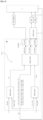
- FIG 7 schematically represents a particular example of the implementation of the third determination module MOD_DET3 belonging to the control system SYS_C used for the operation of the control loop of the figure 4 .
- the multivariable control C_MULTI is determined, in accordance with the invention, so as to optimize a constraint for monitoring the variations dU and dPelec, as well as to respect the operating limits considered for the turbomachine T.
- the multivariable control C_MULTI can be seen as the solution to an optimization problem under constraints.
- the coefficients a, b, c, d and e are given coefficients. More specifically, these are coefficients reflecting a choice of modeling of the variations dU, dU1_MULTI, dU2_MULTI, dWf_MULTI and dPelec.
- the coefficients a, b, c, d and e reflect the choice that the dependence between variations dU, dU1_MULTI, dU2_MULTI, dWf_MULTI and dPelec is locally linear (or equivalently, piecewise linear).
- these coefficients a, b, c, d and e are implemented in the form of interpolation maps (function of N1, N2, P1, and P2). It is also possible to consider an online linearization of the model used.
- Said coefficients a, b, c, d and e are obtained before the implementation of the control method according to the invention, for example following identification tests on a bench, or by using pre-recorded in-flight data, or by means of turbomachine modeling software.
- the index “T” in the exponent of a vector/matrix corresponds, in a classical manner, to the transposition operator.
- the constrained optimization problem considered in the present exemplary embodiment includes an equality constraint given above by means of the matrix comprising the coefficients a, b, c, d and e, as well as a plurality of inequality constraints, namely: dWf _ MIN ⁇ dWf _ MULTI ⁇ dWf _ MAX dU 1 _ MIN ⁇ dU 1 _ MULTI ⁇ dU 1 _ MAX dU 2 _ MIN ⁇ dU 2 _ MULTI ⁇ dU 2 _ MAX d ⁇ _ MIN ⁇ d ⁇ ⁇ d ⁇ _ MAX dT 49 ⁇ dt _ MAX
- the matrix V of the equality constraint whose components are v1 and v2, corresponds to a regularization parameter allowing the constraint of monitoring the variations dU and dPelec to be relaxed.
- said matrix V allows the control objectives to be deviated from when their achievement is no longer possible while respecting the inequality constraints given above.
- the matrices Q1 and Q2 correspond to given weight matrices.
- the matrix Q1 is a weight matrix which makes it possible to minimize the variations of the control variables, and which can be chosen, for example, so as to favor the use of one control variable over another in the context of controlling the turbomachine T.
- the Q2 matrix for its part, is a weight matrix which makes it possible to minimize the deviation from the control objectives, and which can for example be chosen so as to favor one control objective over another.
- the Q2 matrix can be chosen so that the regulation of the engine speed is favored during transient phases with respect to electrical injections/sampling.
- the optimization problem for determining the C_MULTI command can be solved online in real time.
- an offline solution can of course be considered, the optimization problem being then transformed into a multivariate interpolation map.
- FIG 8 represents, in the form of a flowchart, a particular mode of the control method according to the invention, implemented by the control system SYS_C of the figure 3 .
- the control method firstly comprises a step E10 of determining, for said HP shaft 22, the variation dU of total mechanical power.
- This step E10 is implemented by the first determination module MOD_DET1.
- the control method also includes a step E20 for determining, for all the electrical machines M1, M2, the variation dPelec of power injection/extraction.
- This step E20 is implemented by the second determination module MOD_DET2.
- step E10 is executed before step E20.
- step E20 is executed before step E10, or in which steps E10 and E20 are executed in parallel.
- the control method then includes a step E30 for determining the multivariable command C_MULTI.
- This step E30 is implemented by the third determination module MOD_DET3.
- the components of the multivariable control C_MULTI can then be transmitted to the relevant actuators (electric machines M1 and M2, fuel system SYS_CARBU), so as to enable control of the turbomachine T.
- Steps E10, E20 and E30 are subsequently iterated so as to allow time control of the turbomachine T.
- the frequency at which said steps E10, E20 and E30 are iterated corresponds to the calculation frequency of the FADEC 20, for example a frequency between 50 Hz and 100 Hz.
- this other example of implementation includes all of the technical characteristics described above, but also aims to provide the SYS_C control system with an additional functionality (via a fourth determination module described below) to ensure tolerance in the face of possible failures on the electrical chains (uncontrolled variations in injections/power withdrawals, electrical network that cannot meet the needs defined by the U1 and U2 commands, delay in the application of the U1 and U2 commands once they have been transmitted to the MOD_ELEC control module, etc.), or poor coordination between the control of the fuel flow and the control of the M1, M2 electrical machines.
- the turbomachine T has a general structural configuration in accordance with that described above with reference to the figure 2 . Also, the reference signs of the figure 2 relating to the mechanical components of the turbomachine T are reproduced below.
- the set of signals E_S comprise, for the control of the turbomachine T, the signals S_P1, S_P2, S_N1, S_N2 and S_Wf already described previously, but also a power variation signal S_dP1 (respectively a power variation signal S_dP2) injected/taken from the BP shaft 21 (respectively from the HP shaft 22).
- FIG 9 schematically represents a second example of hardware architecture of the SYS_C control system belonging to the turbomachine T of the figure 2 .
- control system SYS_C has the hardware architecture of a computer, and comprises, in particular, a processor 1_2, a random access memory 2_2, a read only memory 3_2 and a non-volatile memory 4_2. It also has communication means 5_2.
- the third and fourth modules MOD_DET3, MOD_DET4 (and therefore a fortiori the control system SYS_C in its entirety) are configured so that the only fuel flow command intended to be executed for the control of the turbomachine T, among said command Wf_MONO and the fuel flow component Wf_MULTI of the multivariable command C_MULTI, is said command Wf_MONO.
- the execution of the command Wf_MONO has priority over the execution of the fuel flow component Wf_MULTI of the multivariable command C_MULTI.
- the fuel flow component Wf_MULTI becomes optional.
- the fuel flow component Wf_MULTI is executed (i.e. is transmitted to the combustion chamber 13) only if the fourth module MOD_DET4 encounters a problem preventing it from generating the Wf_MONO command.
- FIG 10 schematically represents another particular example of operation of the control loop of the turbomachine T, as implemented by means, in particular, of the control system SYS_C of the figure 9 .
- the first, second and third determination modules MOD_DET1, MOD_DET2, MOD_DET3 are for example respectively configured according to the exemplary embodiments of the figures 5, 6 And 7 .
- control loop of the figure 10 differs from that of the figure 4 in that the control system SYS_C now also includes said fourth determination module MOD_DET4.
- the fourth determination module MOD_DET4 receives as input, in particular, the variation dU, the signals S_P1, S_P2, S_dP1, S_dP2, S_N1, S_N2, S_Wf, S_Pt3, S_Pt25 and S_T49, as well as the limits Wf_MULTI_MIN, Wf_MULTI_MAX. From these signals and limits received as input, the fourth determination module MOD_DET4 is able to determine the monovariable control Wf_MONO.
- the Wf_MONO component is then routed to the SYS_CARBU fuel system of the turbomachine T (instead of the Wf_MULTI command which remains optional as mentioned previously), so that the fuel flow injected into the combustion chamber 13 complies with said Wf_MONO command.
- FIG 11 schematically represents a particular example of the implementation of the fourth determination module MOD_DET4 belonging to the control system SYS_C used for the operation of the control loop of the figure 10 .
- a variable (this may be a variable of a measured signal, as in the case of dP1 and dP2, or a variable of a signal determined according to the invention, as in the case of the variation dU) results from an objective consisting of being able to compare with each other values of said variable which are not all acquired or determined under identical conditions. In other words, it is a question of being able to free oneself from the ambient conditions in which such values are acquired or determined in order to make them comparable with each other.
- the reduction (correction) of variables is a technique well known to those skilled in the art, who also knows how to go from a reduced variable to a non-reduced variable.
- the fourth determination module MOD_DET4 comprises different sub-modules, including a first sub-module SS1_MOD_DET4 configured to receive as input the variation dU, the signals S_P1, S_P2, S_dP1, S_dP2, S_N1, S_N2, the values T0, P0 and M and the variations dWf_MAX, dWf_MIN, as well as to determine, from these inputs, a variation dWf1 for the fuel flow rate variable alone.
- the fourth determination module MOD_DET4 also comprises a fifth submodule SS5_MOD_DET4 configured to receive as input the variation the variations dWf1, dWf2_MAX, dWf2_MIN, dWf3_MAX, dWf3_MIN, dWf4_MAX, dWf4_MIN, as well as to determine, from these inputs, a variation dWf_MONO for the fuel flow rate variable alone.
- a fifth submodule SS5_MOD_DET4 configured to receive as input the variation the variations dWf1, dWf2_MAX, dWf2_MIN, dWf3_MAX, dWf3_MIN, dWf4_MAX, dWf4_MIN, as well as to determine, from these inputs, a variation dWf_MONO for the fuel flow rate variable alone.
- the variation dWf_MONO is determined by taking into account the smallest of the variations among dWf2_MIN, dWf3_MIN, dWf4_MIN as well as the largest of the variations dWf2_MAX, dWf3_MAX, dWf4_MAX.
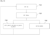
- FIG 12 represents, in the form of a flowchart, a particular mode of implementation of the control method according to the invention, by the control system SYS_C of the figure 9 .
- control method comprises steps F10, F20 and F30 respectively identical to steps E10, E20 and E30 described above with reference to the method of implementing the figure 8 .
- the control method also includes a step F40 for determining the monovariable command Wf_MONO.
- This step F40 is implemented by the fourth determination module MOD_DET4.
- step F40 is executed in parallel with step F30.
- step F40 is executed before or even after step F30.
- the command Wf_MONO has priority over the component WF_MULTI of the command C_MULTI, as has already been mentioned previously.
- Steps F10, F20, F30 and F40 are subsequently iterated so as to allow time control of the turbomachine T.
- the frequency at which said steps F10, F20, F30 and F40 are iterated corresponds to the calculation frequency of the FADEC 20, for example 50 Hz.
- control system also comprises an obtaining module configured to obtain said signals of the E_S set.
Landscapes
- Engineering & Computer Science (AREA)
- Chemical & Material Sciences (AREA)
- Combustion & Propulsion (AREA)
- Mechanical Engineering (AREA)
- General Engineering & Computer Science (AREA)
- Control Of Eletrric Generators (AREA)
- Control Of Positive-Displacement Air Blowers (AREA)
Claims (12)
- Verfahren zum Steuern einer Turbomaschine (T), die mit einem Gasgenerator ausgestattet ist, der jeweils eine Drehwelle für Niederdruck (21) und eine für Hochdruck (22) umfasst, die Turbomaschine umfassend mindestens eine elektrische Maschine (ME1, ME2), die eine Leistungseinspeisungs-/-entnahmevorrichtung auf einer der Drehwellen bildet, das Verfahren umfassend Schritte, die in einer Steuerungsschleife beinhaltet sind, und umfassend:- eine Bestimmung (E10, F10), für mindestens eine Welle und abhängig von einem Drehzahlvorgabewert (N2_REQ), der mit der mindestens einen Welle assoziiert ist, einer Variation dU einer mechanischen Leistungsregelung,- eine Bestimmung (E20, F20), für die Gesamtheit der elektrischen Maschinen und abhängig von einem Einspeisungs-/Entnahme-Vorgabewert (Pelec_REQ), der mit der Gesamtheit der elektrischen Maschinen assoziiert ist, einer Variation dPelec einer Leistungseinspeisungs-/-entnahme-Regelung,- eine Bestimmung (E30, F30) einer multivariaten Regelung (C_MULTI), umfassend eine Kraftstoffdurchflussmengen-Komponente (Wf_MULTI) sowie eine Leistungseinspeisungs-/-entnahmekomponente (U1, U2) für jede elektrische Maschine, wobei die multivariate Regelung zu Folgendem bestimmt wird:• Optimieren eines Vorgabewerts zur Verfolgung der Variationen dU und dPelec,• Einhalten von Betriebsgrenzen der Turbomaschine.
- Verfahren nach Anspruch 1, wobei die Schritte, die in der Steuerungsschleife beinhaltet sind, ferner umfassend einen Bestimmungsschritts (F40) einer monovariablen Kraftstoffdurchflussmengen-Regelung (Wf_MONO) abhängig von der Variation dU, von Betriebsgrenzen der Turbomaschine sowie von aktuellen Einspeise-/Entnahmewerten für den Satz elektrischer Maschinen, wobei die einzige Kraftstoffdurchflussmengen-Regelung, die zum Ausführen der Steuerung der Turbomaschine (T) bestimmt ist, von der monovariablen Regelung und der Kraftstoffdurchflussmengen-Komponente (Wf_MULTI) der multivariablen Regelung (C_MULTI) die monovariable Regelung ist.
- Verfahren nach einem der Ansprüche 1 bis 2, wobei die Betriebsgrenzen Folgendes umfassen:- eine Untergrenze (n_MIN) und eine Obergrenze (n_MAX) eines Verhältnisses zwischen den Druckwerten an dem Ausgang und an dem Eingang eines Hochdruckkompressors (12), der zu dem Gasgenerator gehört, um einen Schutz gegen Pump- und Flammenlöschphänomene zu gewährleisten, und/oder- für mindestens eine Turbine (14, 15), die zu dem Gasgenerator unter einer Niederdruckturbine (15) und einer Hochdruckturbine (14) gehört, eine Obergrenze (t_MAX) der Temperatur der Turbine.
- Verfahren nach einem der Ansprüche 1 bis 3, wobei die Turbomaschine (T) eine erste elektrische Maschine (ME1), die eine Leistungseinspeisungs-/-entnahmevorrichtung auf der Niederdruckdrehwelle (21) bildet, und eine zweite elektrische Maschine (ME2), die eine Leistungseinspeisungs-/-entnahmevorrichtung auf der Hochdruckdrehwelle (22) bildet, umfasst.
- Verfahren nach Anspruch 4, wobei der Vorgabewert zur Verfolgung der Variationen dU und dPelec wie folgt geschrieben wird:
 - a, b, c, d und e gegebene Koeffizienten sind,- dWf_MULTI, dUl_MULTI und dU2_MULTI jeweils beschränkten Variationen der Kraftstoffdurchflussmengen-Komponente (Wf_MULTI) der Leistungseinspeisungs-/-entnahmekomponente (U1) für die erste elektrische Maschine (ME1) und die Leistungseinspeisungs-/-entnahmekomponente (U2) für die zweite elektrische Maschine (ME2) entsprechen,- die Matrix V, deren Komponenten v1 und v2 gegeben sind, einem Regularisierungsparameter entspricht, der es ermöglicht, den Vorgabewert zur Verfolgung der Variationen dU und dPelec zu lockern,und wobei die Optimierung des Vorgabewerts zur Verfolgung darin besteht, eine Kostenfunktion J zu minimieren, die wie folgt ausgedrückt wird:
 wobei Q1 und Q2 Matrizen mit gegebenen Gewichtungen sind.
 - Verfahren nach einem der Ansprüche 1 bis 5, wobei die mindestens eine Welle, die bei der Bestimmung der Änderung dU berücksichtigt wird, die Niederdruckdrehwelle (21) ist, wenn die Steuerungsschleife während einer stabilisierten Betriebsphase der Turbomaschine (T) implementiert wird, und die Hochdruckdrehwelle (22) ist, wenn die Steuerungsschleife während einer transitorischen Betriebsphase der Turbomaschine implementiert wird.
- Computerprogramm, umfassend Anweisungen zum Implementieren eines Prüfverfahrens nach einem der Ansprüche 1 bis 6, wenn das Computerprogramm von einem Computer ausgeführt wird.
- Computerlesbares Speichermedium, auf dem ein Computerprogramm nach Anspruch 7 gespeichert ist.
- Steuerungssystem (SYS_C) einer Turbomaschine (T), die mit einem Gasgenerator ausgestattet ist, der jeweils eine Drehwelle für Niederdruck (21) und eine für Hochdruck (22) umfasst, die Turbomaschine umfassend mindestens eine elektrische Maschine (ME1, ME2), die eine Leistungseinspeisungs-/-entnahmevorrichtung auf einer der Drehwellen bildet, das System umfassend:- ein erstes Bestimmungsmodul (MOD_DETl), das konfiguriert ist, um für mindestens eine Welle und abhängig von einem Drehzahlvorgabewert (N2_REQ), der mit der mindestens einen Welle assoziiert ist, eine Variation dU einer mechanischen Leistungsregelung zu bestimmen,- ein zweites Bestimmungsmodul (MOD_DET2), das konfiguriert ist, um für die Gesamtheit der elektrischen Maschinen und abhängig von einem Einspeisungs-/Entnahme-Vorgabewert (Pelec_REQ), der mit der Gesamtheit der elektrischen Maschinen assoziiert ist, eine Variation dPelec einer Leistungseinspeisungs-/-entnahme-Regelung zu bestimmen,- ein drittes Bestimmungsmodul (MOD_DET3), das konfiguriert ist, um eine multivariate Regelung (C_MULTI) zu bestimmen, umfassend eine Kraftstoffdurchflussmengen-Komponente (Wf_MULTI) sowie eine Leistungseinspeisungs-/-entnahmekomponente (U1, U2) für jede elektrische Maschine, wobei die multivariate Regelung zu Folgendem bestimmt wird:• Optimieren eines Vorgabewerts zur Verfolgung der Variationen dU und dPelec,• Einhalten von Betriebsgrenzen der Turbomaschine.
- System (SYS_C) nach Anspruch 9, wobei das System ferner ein viertes Bestimmungsmodul (MOD_DET4) umfasst, das konfiguriert ist, um eine monovariable Regelung (Wf_MONO) für Kraftstoffflussmenge abhängig von der Variation dU, Betriebsgrenzen der Turbomaschine sowie aktuelle Einspeisungs-/Entnahmewerte für den Satz von elektrischen Maschinen zu bestimmen, wobei die einzige Kraftstoffdurchflussmengen-Regelung, die zum Ausführen der Steuerung der Turbomaschine (T) bestimmt ist, von der monovariablen Regelung und der Kraftstoffdurchflussmengen-Komponente (Wf_MULTI) der multivariablen Regelung (C_MULTI) die monovariable Regelung ist.
- Turbomaschine (T), die mit einem Gasgenerator ausgestattet ist, der eine Drehwelle für Niederdruck (21) und eine für Hochdruck (22) umfasst, die Turbomaschine umfassend mindestens eine elektrische Maschine (ME1, ME2), die eine Leistungseinspeisungs-/-entnahmevorrichtung auf mindestens eine der Drehwellen bildet, sowie ein Steuersystem (SYS_C) nach einem der Ansprüche 9 und 10.
- Luftfahrzeug, umfassend eine Turbomaschine nach Anspruch 11.
Applications Claiming Priority (2)
| Application Number | Priority Date | Filing Date | Title |
|---|---|---|---|
| FR2104799A FR3122702B1 (fr) | 2021-05-06 | 2021-05-06 | Procédé de contrôle d’une turbomachine comportant au moins une machine électrique, système de contrôle associé |
| PCT/FR2022/050861 WO2022234232A1 (fr) | 2021-05-06 | 2022-05-04 | Procede de controle d'une turbomachine comportant au moins une machine electrique, systeme de controle associe |
Publications (2)
| Publication Number | Publication Date |
|---|---|
| EP4334582A1 EP4334582A1 (de) | 2024-03-13 |
| EP4334582B1 true EP4334582B1 (de) | 2025-01-15 |
Family
ID=76601393
Family Applications (1)
| Application Number | Title | Priority Date | Filing Date |
|---|---|---|---|
| EP22724819.2A Active EP4334582B1 (de) | 2021-05-06 | 2022-05-04 | Verfahren zur steuerung einer turbomaschine mit mindestens einer elektrischen maschine und zugehöriges steuerungssystem |
Country Status (5)
| Country | Link |
|---|---|
| US (1) | US12281621B2 (de) |
| EP (1) | EP4334582B1 (de) |
| CN (1) | CN117597505A (de) |
| FR (1) | FR3122702B1 (de) |
| WO (1) | WO2022234232A1 (de) |
Families Citing this family (1)
| Publication number | Priority date | Publication date | Assignee | Title |
|---|---|---|---|---|
| FR3143557A1 (fr) * | 2022-12-20 | 2024-06-21 | Safran | procédé et système de régulation dans un système propulsif |
Family Cites Families (5)
| Publication number | Priority date | Publication date | Assignee | Title |
|---|---|---|---|---|
| FR3024755B1 (fr) | 2014-08-08 | 2019-06-21 | Safran Aircraft Engines | Hybridation des compresseurs d'un turboreacteur |
| US11230385B2 (en) * | 2017-06-08 | 2022-01-25 | General Electric Company | Hybrid-electric propulsion system for an aircraft |
| FR3087491B1 (fr) * | 2018-10-18 | 2020-11-06 | Safran Aircraft Engines | Procede de commande d'une turbomachine comportant un moteur electrique |
| US10968765B2 (en) * | 2018-12-04 | 2021-04-06 | General Electric Company | Power system with a coordinated power draw |
| GB2589193B (en) * | 2019-08-23 | 2022-09-21 | Raytheon Tech Corp | Augmented drive of compressors via differential and multistage turbine |
-
2021
- 2021-05-06 FR FR2104799A patent/FR3122702B1/fr active Active
-
2022
- 2022-05-04 WO PCT/FR2022/050861 patent/WO2022234232A1/fr not_active Ceased
- 2022-05-04 CN CN202280046225.3A patent/CN117597505A/zh active Pending
- 2022-05-04 EP EP22724819.2A patent/EP4334582B1/de active Active
- 2022-05-04 US US18/559,218 patent/US12281621B2/en active Active
Also Published As
| Publication number | Publication date |
|---|---|
| US12281621B2 (en) | 2025-04-22 |
| US20240229727A1 (en) | 2024-07-11 |
| WO2022234232A1 (fr) | 2022-11-10 |
| FR3122702A1 (fr) | 2022-11-11 |
| CN117597505A (zh) | 2024-02-23 |
| EP4334582A1 (de) | 2024-03-13 |
| FR3122702B1 (fr) | 2023-05-12 |
Similar Documents
| Publication | Publication Date | Title |
|---|---|---|
| EP2864616B1 (de) | Verfahren zur einstellung eines referenzwerts eines parameters zur beeinflussung des schubs eines gasturbinentriebwerks | |
| CA2942639C (fr) | Procede de gestion globale optimisee d'un reseau energetique d'un aeronef et dispositif correspondant | |
| EP3186489B1 (de) | Vorrichtung und verfahren zum starten einer gasturbine, verfahren zur regelung der drehzahl einer gasturbine und zugehörige gasturbine und turbinenmotor | |
| EP4259521B1 (de) | Hybrides antriebssystem für einen hubschrauber | |
| EP2925602A1 (de) | Steuerungsvorrichtung für einen motor | |
| EP3464855A1 (de) | Flugzeugturbinentriebwerk mit epizyklischem untersetzungsgetriebe mit variablem übersetzungsverhältnis | |
| EP3149313B1 (de) | Verfahren und vorrichtung zur steuerung einer schubkraft eines strahltriebwerks | |
| WO2021181027A1 (fr) | Procédé de contrôle d'une turbomachine comportant une machine électrique | |
| EP3338147A1 (de) | System zur steuerung eines gesteuerten parameters | |
| EP4334582B1 (de) | Verfahren zur steuerung einer turbomaschine mit mindestens einer elektrischen maschine und zugehöriges steuerungssystem | |
| WO2023012435A1 (fr) | Turbopropulseur apte à fournir une fonction d'éolienne de secours et aéronef comportant un tel turbopropulseur | |
| WO2014068236A1 (fr) | Unite de commande et procede de pilotage de jeu en sommet d'aubes. | |
| EP4627206A1 (de) | Steuerungsverfahren und steuerungsvorrichtung für einen hybridturbinenmotor | |
| EP3829978B1 (de) | Verfahren zur steuerung des antriebsschubs eines flugzeugs | |
| WO2018138456A1 (fr) | Circuit d'alimentation en carburant de turbomachine | |
| FR3043432A1 (fr) | Procede et dispositif d'ajustement de valeurs de consigne d'une pluralite de geometries variables determinees d'une turbomachine | |
| EP4462219A1 (de) | Verfahren und vorrichtung zum routen eines zweimotorigen flugzeugs mit ökonomischem betriebsmodus | |
| EP3947936B1 (de) | Verfahren und system zur steuerung eines nichtantriebsenergieerzeugungsturbinenmotors | |
| EP4673370A1 (de) | Verfahren zur kompensation der elektrischen leistung eines hybridturbinenmotors | |
| FR3164739A1 (fr) | Procédé de commande de turbomachine hybridée | |
| EP4623194A1 (de) | Verfahren und vorrichtung zur leerlaufgeschwindigkeitswartungssteuerung | |
| WO2024180295A1 (fr) | Procédé de contrôle du taux d'hybridation d'une turbomachine hybridée | |
| FR3149310A1 (fr) | Contrôle d’un système électrique | |
| CA3131143A1 (fr) | Procede et systeme de commande d'une turbomachine avec gestion des saturations de commande |
Legal Events
| Date | Code | Title | Description |
|---|---|---|---|
| STAA | Information on the status of an ep patent application or granted ep patent |
Free format text: STATUS: UNKNOWN |
|
| STAA | Information on the status of an ep patent application or granted ep patent |
Free format text: STATUS: THE INTERNATIONAL PUBLICATION HAS BEEN MADE |
|
| PUAI | Public reference made under article 153(3) epc to a published international application that has entered the european phase |
Free format text: ORIGINAL CODE: 0009012 |
|
| STAA | Information on the status of an ep patent application or granted ep patent |
Free format text: STATUS: REQUEST FOR EXAMINATION WAS MADE |
|
| 17P | Request for examination filed |
Effective date: 20231129 |
|
| AK | Designated contracting states |
Kind code of ref document: A1 Designated state(s): AL AT BE BG CH CY CZ DE DK EE ES FI FR GB GR HR HU IE IS IT LI LT LU LV MC MK MT NL NO PL PT RO RS SE SI SK SM TR |
|
| DAV | Request for validation of the european patent (deleted) | ||
| DAX | Request for extension of the european patent (deleted) | ||
| GRAP | Despatch of communication of intention to grant a patent |
Free format text: ORIGINAL CODE: EPIDOSNIGR1 |
|
| STAA | Information on the status of an ep patent application or granted ep patent |
Free format text: STATUS: GRANT OF PATENT IS INTENDED |
|
| GRAS | Grant fee paid |
Free format text: ORIGINAL CODE: EPIDOSNIGR3 |
|
| GRAA | (expected) grant |
Free format text: ORIGINAL CODE: 0009210 |
|
| STAA | Information on the status of an ep patent application or granted ep patent |
Free format text: STATUS: THE PATENT HAS BEEN GRANTED |
|
| INTG | Intention to grant announced |
Effective date: 20241125 |
|
| AK | Designated contracting states |
Kind code of ref document: B1 Designated state(s): AL AT BE BG CH CY CZ DE DK EE ES FI FR GB GR HR HU IE IS IT LI LT LU LV MC MK MT NL NO PL PT RO RS SE SI SK SM TR |
|
| REG | Reference to a national code |
Ref country code: CH Ref legal event code: EP Ref country code: GB Ref legal event code: FG4D Free format text: NOT ENGLISH |
|
| REG | Reference to a national code |
Ref country code: DE Ref legal event code: R096 Ref document number: 602022009621 Country of ref document: DE |
|
| REG | Reference to a national code |
Ref country code: IE Ref legal event code: FG4D Free format text: LANGUAGE OF EP DOCUMENT: FRENCH |
|
| REG | Reference to a national code |
Ref country code: NL Ref legal event code: MP Effective date: 20250115 |
|
| PG25 | Lapsed in a contracting state [announced via postgrant information from national office to epo] |
Ref country code: NL Free format text: LAPSE BECAUSE OF FAILURE TO SUBMIT A TRANSLATION OF THE DESCRIPTION OR TO PAY THE FEE WITHIN THE PRESCRIBED TIME-LIMIT Effective date: 20250115 |
|
| PG25 | Lapsed in a contracting state [announced via postgrant information from national office to epo] |
Ref country code: RS Free format text: LAPSE BECAUSE OF FAILURE TO SUBMIT A TRANSLATION OF THE DESCRIPTION OR TO PAY THE FEE WITHIN THE PRESCRIBED TIME-LIMIT Effective date: 20250415 |
|
| PG25 | Lapsed in a contracting state [announced via postgrant information from national office to epo] |
Ref country code: FI Free format text: LAPSE BECAUSE OF FAILURE TO SUBMIT A TRANSLATION OF THE DESCRIPTION OR TO PAY THE FEE WITHIN THE PRESCRIBED TIME-LIMIT Effective date: 20250115 |
|
| PG25 | Lapsed in a contracting state [announced via postgrant information from national office to epo] |
Ref country code: PL Free format text: LAPSE BECAUSE OF FAILURE TO SUBMIT A TRANSLATION OF THE DESCRIPTION OR TO PAY THE FEE WITHIN THE PRESCRIBED TIME-LIMIT Effective date: 20250115 |
|
| PGFP | Annual fee paid to national office [announced via postgrant information from national office to epo] |
Ref country code: DE Payment date: 20250519 Year of fee payment: 4 |
|
| PG25 | Lapsed in a contracting state [announced via postgrant information from national office to epo] |
Ref country code: ES Free format text: LAPSE BECAUSE OF FAILURE TO SUBMIT A TRANSLATION OF THE DESCRIPTION OR TO PAY THE FEE WITHIN THE PRESCRIBED TIME-LIMIT Effective date: 20250115 |
|
| REG | Reference to a national code |
Ref country code: LT Ref legal event code: MG9D |
|
| PG25 | Lapsed in a contracting state [announced via postgrant information from national office to epo] |
Ref country code: IS Free format text: LAPSE BECAUSE OF FAILURE TO SUBMIT A TRANSLATION OF THE DESCRIPTION OR TO PAY THE FEE WITHIN THE PRESCRIBED TIME-LIMIT Effective date: 20250515 Ref country code: NO Free format text: LAPSE BECAUSE OF FAILURE TO SUBMIT A TRANSLATION OF THE DESCRIPTION OR TO PAY THE FEE WITHIN THE PRESCRIBED TIME-LIMIT Effective date: 20250415 |
|
| REG | Reference to a national code |
Ref country code: AT Ref legal event code: MK05 Ref document number: 1759977 Country of ref document: AT Kind code of ref document: T Effective date: 20250115 |
|
| PG25 | Lapsed in a contracting state [announced via postgrant information from national office to epo] |
Ref country code: HR Free format text: LAPSE BECAUSE OF FAILURE TO SUBMIT A TRANSLATION OF THE DESCRIPTION OR TO PAY THE FEE WITHIN THE PRESCRIBED TIME-LIMIT Effective date: 20250115 |
|
| PG25 | Lapsed in a contracting state [announced via postgrant information from national office to epo] |
Ref country code: LV Free format text: LAPSE BECAUSE OF FAILURE TO SUBMIT A TRANSLATION OF THE DESCRIPTION OR TO PAY THE FEE WITHIN THE PRESCRIBED TIME-LIMIT Effective date: 20250115 Ref country code: PT Free format text: LAPSE BECAUSE OF FAILURE TO SUBMIT A TRANSLATION OF THE DESCRIPTION OR TO PAY THE FEE WITHIN THE PRESCRIBED TIME-LIMIT Effective date: 20250515 |
|
| PGFP | Annual fee paid to national office [announced via postgrant information from national office to epo] |
Ref country code: FR Payment date: 20250526 Year of fee payment: 4 |
|
| PG25 | Lapsed in a contracting state [announced via postgrant information from national office to epo] |
Ref country code: GR Free format text: LAPSE BECAUSE OF FAILURE TO SUBMIT A TRANSLATION OF THE DESCRIPTION OR TO PAY THE FEE WITHIN THE PRESCRIBED TIME-LIMIT Effective date: 20250416 Ref country code: BG Free format text: LAPSE BECAUSE OF FAILURE TO SUBMIT A TRANSLATION OF THE DESCRIPTION OR TO PAY THE FEE WITHIN THE PRESCRIBED TIME-LIMIT Effective date: 20250115 |
|
| PG25 | Lapsed in a contracting state [announced via postgrant information from national office to epo] |
Ref country code: AT Free format text: LAPSE BECAUSE OF FAILURE TO SUBMIT A TRANSLATION OF THE DESCRIPTION OR TO PAY THE FEE WITHIN THE PRESCRIBED TIME-LIMIT Effective date: 20250115 |
|
| PG25 | Lapsed in a contracting state [announced via postgrant information from national office to epo] |
Ref country code: SE Free format text: LAPSE BECAUSE OF FAILURE TO SUBMIT A TRANSLATION OF THE DESCRIPTION OR TO PAY THE FEE WITHIN THE PRESCRIBED TIME-LIMIT Effective date: 20250115 |
|
| PG25 | Lapsed in a contracting state [announced via postgrant information from national office to epo] |
Ref country code: SM Free format text: LAPSE BECAUSE OF FAILURE TO SUBMIT A TRANSLATION OF THE DESCRIPTION OR TO PAY THE FEE WITHIN THE PRESCRIBED TIME-LIMIT Effective date: 20250115 |
|
| PG25 | Lapsed in a contracting state [announced via postgrant information from national office to epo] |
Ref country code: DK Free format text: LAPSE BECAUSE OF FAILURE TO SUBMIT A TRANSLATION OF THE DESCRIPTION OR TO PAY THE FEE WITHIN THE PRESCRIBED TIME-LIMIT Effective date: 20250115 |
|
| PG25 | Lapsed in a contracting state [announced via postgrant information from national office to epo] |
Ref country code: IT Free format text: LAPSE BECAUSE OF FAILURE TO SUBMIT A TRANSLATION OF THE DESCRIPTION OR TO PAY THE FEE WITHIN THE PRESCRIBED TIME-LIMIT Effective date: 20250115 |
|
| REG | Reference to a national code |
Ref country code: DE Ref legal event code: R097 Ref document number: 602022009621 Country of ref document: DE |
|
| PG25 | Lapsed in a contracting state [announced via postgrant information from national office to epo] |
Ref country code: EE Free format text: LAPSE BECAUSE OF FAILURE TO SUBMIT A TRANSLATION OF THE DESCRIPTION OR TO PAY THE FEE WITHIN THE PRESCRIBED TIME-LIMIT Effective date: 20250115 Ref country code: CZ Free format text: LAPSE BECAUSE OF FAILURE TO SUBMIT A TRANSLATION OF THE DESCRIPTION OR TO PAY THE FEE WITHIN THE PRESCRIBED TIME-LIMIT Effective date: 20250115 |
|
| PG25 | Lapsed in a contracting state [announced via postgrant information from national office to epo] |
Ref country code: RO Free format text: LAPSE BECAUSE OF FAILURE TO SUBMIT A TRANSLATION OF THE DESCRIPTION OR TO PAY THE FEE WITHIN THE PRESCRIBED TIME-LIMIT Effective date: 20250115 |
|
| PG25 | Lapsed in a contracting state [announced via postgrant information from national office to epo] |
Ref country code: SK Free format text: LAPSE BECAUSE OF FAILURE TO SUBMIT A TRANSLATION OF THE DESCRIPTION OR TO PAY THE FEE WITHIN THE PRESCRIBED TIME-LIMIT Effective date: 20250115 |
|
| PLBE | No opposition filed within time limit |
Free format text: ORIGINAL CODE: 0009261 |
|
| STAA | Information on the status of an ep patent application or granted ep patent |
Free format text: STATUS: NO OPPOSITION FILED WITHIN TIME LIMIT |
|
| REG | Reference to a national code |
Ref country code: CH Ref legal event code: L10 Free format text: ST27 STATUS EVENT CODE: U-0-0-L10-L00 (AS PROVIDED BY THE NATIONAL OFFICE) Effective date: 20251126 |
|
| REG | Reference to a national code |
Ref country code: CH Ref legal event code: H13 Free format text: ST27 STATUS EVENT CODE: U-0-0-H10-H13 (AS PROVIDED BY THE NATIONAL OFFICE) Effective date: 20251223 |
|
| 26N | No opposition filed |
Effective date: 20251016 |
|
| PG25 | Lapsed in a contracting state [announced via postgrant information from national office to epo] |
Ref country code: LU Free format text: LAPSE BECAUSE OF NON-PAYMENT OF DUE FEES Effective date: 20250504 |
|
| PG25 | Lapsed in a contracting state [announced via postgrant information from national office to epo] |
Ref country code: CH Free format text: LAPSE BECAUSE OF NON-PAYMENT OF DUE FEES Effective date: 20250531 |
|
| REG | Reference to a national code |
Ref country code: BE Ref legal event code: MM Effective date: 20250531 |
|
| PG25 | Lapsed in a contracting state [announced via postgrant information from national office to epo] |
Ref country code: MC Free format text: LAPSE BECAUSE OF FAILURE TO SUBMIT A TRANSLATION OF THE DESCRIPTION OR TO PAY THE FEE WITHIN THE PRESCRIBED TIME-LIMIT Effective date: 20250115 |
|
| PG25 | Lapsed in a contracting state [announced via postgrant information from national office to epo] |
Ref country code: IE Free format text: LAPSE BECAUSE OF NON-PAYMENT OF DUE FEES Effective date: 20250504 |
|
| PG25 | Lapsed in a contracting state [announced via postgrant information from national office to epo] |
Ref country code: BE Free format text: LAPSE BECAUSE OF NON-PAYMENT OF DUE FEES Effective date: 20250531 |