EP4334585B1 - Noise reducing wind turbine blade - Google Patents
Noise reducing wind turbine blade Download PDFInfo
- Publication number
- EP4334585B1 EP4334585B1 EP22726737.4A EP22726737A EP4334585B1 EP 4334585 B1 EP4334585 B1 EP 4334585B1 EP 22726737 A EP22726737 A EP 22726737A EP 4334585 B1 EP4334585 B1 EP 4334585B1
- Authority
- EP
- European Patent Office
- Prior art keywords
- cavity
- serration
- wind turbine
- resonator
- blade
- Prior art date
- Legal status (The legal status is an assumption and is not a legal conclusion. Google has not performed a legal analysis and makes no representation as to the accuracy of the status listed.)
- Active
Links
Images




Classifications
-
- F—MECHANICAL ENGINEERING; LIGHTING; HEATING; WEAPONS; BLASTING
- F03—MACHINES OR ENGINES FOR LIQUIDS; WIND, SPRING, OR WEIGHT MOTORS; PRODUCING MECHANICAL POWER OR A REACTIVE PROPULSIVE THRUST, NOT OTHERWISE PROVIDED FOR
- F03D—WIND MOTORS
- F03D1/00—Wind motors with rotation axis substantially parallel to the air flow entering the rotor
- F03D1/06—Rotors
- F03D1/0608—Rotors characterised by their aerodynamic shape
- F03D1/0633—Rotors characterised by their aerodynamic shape of the blades
-
- F—MECHANICAL ENGINEERING; LIGHTING; HEATING; WEAPONS; BLASTING
- F03—MACHINES OR ENGINES FOR LIQUIDS; WIND, SPRING, OR WEIGHT MOTORS; PRODUCING MECHANICAL POWER OR A REACTIVE PROPULSIVE THRUST, NOT OTHERWISE PROVIDED FOR
- F03D—WIND MOTORS
- F03D1/00—Wind motors with rotation axis substantially parallel to the air flow entering the rotor
- F03D1/06—Rotors
- F03D1/0608—Rotors characterised by their aerodynamic shape
- F03D1/0633—Rotors characterised by their aerodynamic shape of the blades
- F03D1/06495—Aerodynamic elements attached to or formed with the blade, e.g. flaps, vortex generators or noise reducers
-
- F—MECHANICAL ENGINEERING; LIGHTING; HEATING; WEAPONS; BLASTING
- F03—MACHINES OR ENGINES FOR LIQUIDS; WIND, SPRING, OR WEIGHT MOTORS; PRODUCING MECHANICAL POWER OR A REACTIVE PROPULSIVE THRUST, NOT OTHERWISE PROVIDED FOR
- F03D—WIND MOTORS
- F03D1/00—Wind motors with rotation axis substantially parallel to the air flow entering the rotor
- F03D1/06—Rotors
- F03D1/065—Rotors characterised by their construction elements
- F03D1/0675—Rotors characterised by their construction elements of the blades
-
- F—MECHANICAL ENGINEERING; LIGHTING; HEATING; WEAPONS; BLASTING
- F05—INDEXING SCHEMES RELATING TO ENGINES OR PUMPS IN VARIOUS SUBCLASSES OF CLASSES F01-F04
- F05B—INDEXING SCHEME RELATING TO WIND, SPRING, WEIGHT, INERTIA OR LIKE MOTORS, TO MACHINES OR ENGINES FOR LIQUIDS COVERED BY SUBCLASSES F03B, F03D AND F03G
- F05B2240/00—Components
- F05B2240/20—Rotors
- F05B2240/30—Characteristics of rotor blades, i.e. of any element transforming dynamic fluid energy to or from rotational energy and being attached to a rotor
- F05B2240/304—Details of the trailing edge
- F05B2240/3042—Serrated trailing edge
-
- F—MECHANICAL ENGINEERING; LIGHTING; HEATING; WEAPONS; BLASTING
- F05—INDEXING SCHEMES RELATING TO ENGINES OR PUMPS IN VARIOUS SUBCLASSES OF CLASSES F01-F04
- F05B—INDEXING SCHEME RELATING TO WIND, SPRING, WEIGHT, INERTIA OR LIKE MOTORS, TO MACHINES OR ENGINES FOR LIQUIDS COVERED BY SUBCLASSES F03B, F03D AND F03G
- F05B2260/00—Function
- F05B2260/96—Preventing, counteracting or reducing vibration or noise
-
- F—MECHANICAL ENGINEERING; LIGHTING; HEATING; WEAPONS; BLASTING
- F05—INDEXING SCHEMES RELATING TO ENGINES OR PUMPS IN VARIOUS SUBCLASSES OF CLASSES F01-F04
- F05B—INDEXING SCHEME RELATING TO WIND, SPRING, WEIGHT, INERTIA OR LIKE MOTORS, TO MACHINES OR ENGINES FOR LIQUIDS COVERED BY SUBCLASSES F03B, F03D AND F03G
- F05B2260/00—Function
- F05B2260/96—Preventing, counteracting or reducing vibration or noise
- F05B2260/964—Preventing, counteracting or reducing vibration or noise by damping means
-
- Y—GENERAL TAGGING OF NEW TECHNOLOGICAL DEVELOPMENTS; GENERAL TAGGING OF CROSS-SECTIONAL TECHNOLOGIES SPANNING OVER SEVERAL SECTIONS OF THE IPC; TECHNICAL SUBJECTS COVERED BY FORMER USPC CROSS-REFERENCE ART COLLECTIONS [XRACs] AND DIGESTS
- Y02—TECHNOLOGIES OR APPLICATIONS FOR MITIGATION OR ADAPTATION AGAINST CLIMATE CHANGE
- Y02E—REDUCTION OF GREENHOUSE GAS [GHG] EMISSIONS, RELATED TO ENERGY GENERATION, TRANSMISSION OR DISTRIBUTION
- Y02E10/00—Energy generation through renewable energy sources
- Y02E10/70—Wind energy
- Y02E10/72—Wind turbines with rotation axis in wind direction
Definitions
- the present invention relates to a wind turbine blade having sound or noise reducing means configured to reduce noise emitted at the trailing edge of the blade.
- Wind power is increasingly popular due to its clean and environmentally friendly production of energy.
- the rotor blades of modern wind turbines capture kinetic wind energy by using sophisticated blade design created to maximise efficiency.
- US 2011/0142635 A1 describes a blade extension panel provided with a cutaway mounting portion for mounting the extension panel to the blade such that the blade extension is substantially flush with a surface of the blade.
- a wind turbine blade having a profiled contour and comprising a pressure side and a suction side, a leading edge and a trailing edge, a chord having a chord length extending between the leading edge and the trailing edge, the blade extending in a spanwise direction between a root end and a tip end and having a longitudinal axis, wherein at least a portion of the blade located in a trailing edge region at or adjacent to the trailing edge is a noise reducing portion defining an exposed surface and comprising a plurality of sound reducing or sound absorbing acoustic resonators, each of the resonators comprising an opening in the exposed surface and a cavity having a length between the opening and a bottom of a bottom wall of the cavity opposite the opening, the opening to the cavity having an opening cross-sectional shape defining an opening cross-sectional area and the cavity having a cavity cross-sectional shape defining a cavity cross-sectional area.
- the trailing edge region may include the trailing edge and 1%, 5%, 10%, 20%, 30% ,40% or 50% of the local chord length upstream of the trailing edge.
- the resonators can be configured and dimensioned so that the sound(s) waves emitted by the resonator is approximately 180° out of phase with incoming sound waves.
- the resonators may be arranged close to the sound source region of the blade emitting the sound to be abated by the resonators. It is believed and has been demonstrated that an optimal noise reduction is obtained, when the opening of the resonator or resonators are arranged close to the source emitting the noise to be abated by the resonator or resonators in question, because the most significant portion of energy can be extracted from the coupled hydrodynamic and acoustic field.
- the cross-sectional area of the cavity can be essentially the same as that of the cavity opening.
- the cross-sectional area of the cavity can be larger than that of the cavity opening.
- the cross-sectional area of the cavity can be smaller than that of the cavity opening.
- the cross-sectional area of the cavity may be essentially constant over the entire length thereof, or it can vary, influencing the tuned frequency range.
- the cross-sectional shape of the cavity can be essentially the same as that of the cavity opening.
- the cross-sectional shape can be essentially the same over the entire length of the cavity.
- the cavity may have an elongated shape, the length of the cavity being longer than the transverse dimension of the cavity.
- the length of the cavity is also of importance for the target frequency range.
- the cavity of the resonator can comprise one or more transverse partition walls between the bottom and the opening thereof, the partition wall(s) dividing the cavity into two or more cavity parts, such as an outer cavity part proximal to the cavity opening and an inner cavity part proximal to the cavity bottom, and each transverse partition wall being provided with at least one dividing wall opening.
- the cavity opening(s) can be arranged centrally or not centrally in the partition wall.
- the partition wall(s) may comprise a plurality of mutually spaced cavity openings.
- the length of the cavity parts can be the same or different.
- the resonator can abate emitted sound of different wavelengths and frequencies by dimensioning the cavity and the cavity parts accordingly.
- At least some of the cavity openings can be covered by a fluid permeable layer, such as a fabric layer, a wire mesh, or a perforated screen/facesheet.
- a fluid permeable layer such as a fabric layer, a wire mesh, or a perforated screen/facesheet.
- the impedance of the resonators and their frequency response can be tuned and the sound absorption can be extended over a larger frequency range.
- porous layer may also be used to provide a certain resistance to the flow oscillating in and out of the cavity, thereby allowing to tune its frequency response and optimize the absorption.
- At least one of the plurality of resonators can be a quarter wavelength resonator, such as a resonator with a cavity having constant transverse dimension, and having a cross-sectional dimension being smaller than the length, such as at least 4, 6, 8 or 10 times smaller than the length of the cavity.
- the wavelength ⁇ can theoretically be calculated as approximately 4 L, L being the length of the resonator cavity or chamber, and the frequency f can theoretically be calculated as approximately sound speed/4L.
- the frequency f can be calculated as approximately 340m/s/4L
- the length L of the cavity can be calculated as approximately 340m/s/4f.
- a resonator can, in principle, have any cross-sectional shape.
- the cross-sectional shape of the resonator may typically be circular, elliptical, trapezoidal, hexagonal or rectangular.
- At least one of the plurality of resonators can comprise a cavity being straight, i.e. having a straight resonator axis extending between the cavity opening and the cavity bottom.
- the resonator axis of the at least one resonator can be slanted relative to the local chord, such as in a flap wise or spanwise direction.
- the desired length of the resonator cavity is obtainable by a straight resonator extending in or parallel to the local chord.
- a sufficient length of the resonator cavity is obtainable by slanting the straight resonator relative to the local chord, flap wise or span wise.
- At least one of the plurality of resonators may be curved, i.e. comprise a cavity having a cavity axis being curved for obtaining the desired length of the cavity.
- At least one of the plurality of resonators can be essentially spiral-shaped having a spiral shaped cavity.
- the bottom wall of the cavity of a resonator can form a second bottom of a second cavity of a second resonator formed in continuation of the resonator, the second sound absorbing or reducing resonator comprising a second opening in the noise reducing exposed surface of the blade.
- the second cavity of the second resonator can have a smaller or larger length than or the same length as that of the cavity. Thereby the resonator and the second resonator may abate, reduce or absorb noise of different frequencies.
- the trailing edge of the blade may comprise at least one serrated portion extending at least over a portion between the tip and the root of the blade, the serrated portion comprising a plurality of serrations including a first serration and a second serration, and the noise reducing portion is located in or comprises the at least one serrated portion, at least some of the resonators being arranged in the first and/or second serration.
- the advantage obtained by arranging acoustic resonators in the serration is the noise reduction that may be obtained by the serrations which are further reduced by the acoustic resonators.
- the resonators can be positioned in closest proximity to the noise source region on a blade with serrations.
- the strongest source with serrations is typically remaining at the trailing edge location, respectively in the valley of the serration teeth.
- resonators integrated in serrations and/or 2-dimensional chord extensions they can be attached to an existing wind blade as an add-on without intruding into the structure, keeping the effort and cost of such an enhancement low.
- Each of the first serration and the second serration can comprise
- the serration pressure side can be considered a continuation of and forming a portion of the pressure side of the blade, and the serration suction side can be considered a continuation of and forming a portion of the suction side of the blade.
- the sides of the serrations can also be considered extending upstream of the base portion of the serrations, which means that the resonators can also be arranged in the pressure side and the suction side upstream of the base portion of the serrations.
- the first serration and the second serration can be arranged adjacent to each other, such that a valley region is formed between the first lateral serration side of the first serration and the second lateral serration side of the second serration or vice versa.
- At least some of the resonators arranged in the first and the second serration may be arranged in the first lateral serration side and/or the second lateral serration side thereof.
- Some of the resonators arranged in the first and/or second lateral serration side can be arranged adjacent to or at the base of the serration and thereby also at or adjacent to a nadir in the valley between two serrations.
- the resonators arranged in the first and/or second lateral serration side of the serrations can be linear resonators extending essentially parallel to the local chord, or be undulated resonators, such as S-shaped resonators, extending in the direction of the local chord. However, they can also be undulated resonators, such as S-shaped resonators, extending from one of the lateral serration sides towards the opposite lateral serration side.
- the resonators can also be spiral-shaped.
- the spiral-shaped resonators can have a spiral axis being essentially parallel to or coincide with the local chord.
- At least some of the resonators arranged in the first and the second serration can be arranged in the serration pressure side and/or the serration suction side.
- the serrations can have a rounded cross-sectional shape, such as a rounded rectangular shape. an elliptical or circular cross-sectional shape and taper towards the apex.
- the shape of the serrations can be essentially conical.
- the trailing edge of the blade may comprise a straight portion extending at least over a portion between the tip and the root of the blade, and the noise reducing portion may be located upstream of the straight portion.
- the noise reducing portion can comprise an array of resonators.
- the array of resonators can be arranged in rows and columns.
- the noise reducing portion of the blade can be formed by a premanufactured part being integrated in the blade.
- the noise reducing portion may be advantageous to produce as a separate part, as it can be produced by manufacturing processes that are normally not used for producing a wind turbine blade.
- the noise reducing part can be produced as a relatively small part by an injection moulding process, for example, or an extrusion process with subsequent closing of the cavities and re-shaping by thermoforming or by a casting process using flexible moulds or moulds with lost cores or by 3D-printing and a number of said small parts can be assembled to the desired size and integrated in the blade.
- the premanufactured part may be integrated in the blade during manufacturing of the blade.
- the premanufactured part can be added to an existing previously manufactured blade as an add-on or retrofitted part and thereby integrated in the blade after manufacturing of the blade.
- Fig. 1 illustrates a conventional modern upwind wind turbine 2 according to the so-called "Danish concept" with a tower 4, a nacelle 6 and a rotor with a substantially horizontal rotor shaft.
- the rotor includes a hub 8 and three blades 10 extending essentially radially from the hub 8, each having a blade root 16 nearest the hub and a blade tip 14 furthest from the hub 8.
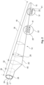
- Fig. 2 shows a schematic view of an exemplary wind turbine blade 10.
- the wind turbine blade 10 has the shape of a conventional wind turbine blade with a root end 17 and a tip end 15 as seen in a longitudinal direction along a longitudinal axis LA of the blade and a transverse direction transversely of the longitudinal direction.
- the blade comprises a root region 30 closest to the hub, a profiled or an airfoil region 34 furthest from the hub and a transition region 32 between the root region 30 and the airfoil region 34.
- the blade 10 comprises a leading edge 18 facing the direction of rotation of the blade 10, when the blade is mounted on the hub, and a trailing edge 20 facing the opposite direction of the leading edge 18 and a local chord 28 having a chord length C as well as a chord plane extending through the local chord 28 perpendicular to the longitudinal axis LA of the blade.
- the blade 10 has a noise reducing portion 41 comprising a serrated trailing edge portion 42 having a plurality of serrations 43, acoustic resonators being located in the noise reducing portion 41.
- the airfoil region 34 (also called the profiled region) has an ideal or almost ideal blade shape with respect to generating lift, whereas the root region 30 due to structural considerations has a substantially circular or elliptical cross-section, which for instance makes it easier and safer to mount the blade 10 to the hub.
- the diameter (or the chord) of the root region 30 may be constant along the entire root region 30.
- the transition region 32 has a transitional profile gradually changing from the circular or elliptical shape of the root region 30 to the airfoil profile of the airfoil region 34.
- the chord length of the transition region 32 typically increases with increasing distance from the hub.
- the airfoil region 34 has an airfoil profile with a chord 28 extending between the leading edge 18 and the trailing edge 20 of the blade 10.
- the length C of the chord decreases with increasing distance from the hub.
- a shoulder 40 of the blade 10 is defined as the position, where the blade 10 has its largest chord length C. The shoulder 40 is typically provided at the boundary between the transition
- chords of the different sections of the blade normally do not lie in a common plane, since the blade may be twisted and/or curved (i.e., pre-bent), thus providing the chord plane with a correspondingly twisted and/or curved course, this being most often the case in order to compensate for the local velocity of the blade being dependent on the radius from the rotation axis.
- the wind turbine blade 10 can typically comprise a blade shell comprising two blade shell parts or half shells, a first blade shell part and a second blade shell part, typically made of fibre-reinforced polymer.
- the wind turbine blade 10 may comprise additional shell parts, such as a third shell part and/or a fourth shell part.
- the first blade shell part is typically a pressure side 24 or upwind blade shell part.
- the second blade shell part is typically a suction side 26 or downwind blade shell part.
- the first blade shell part and the second blade shell part are fastened together with adhesive, such as glue, along bond lines or glue joints extending along the trailing edge 20 and the leading edge 18 of the blade 10.
- the root ends of the blade shell parts have a semi-circular or semi-oval outer cross-sectional shape.
- the blade shell parts define the aerodynamic shape of the wind turbine blade.
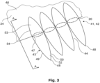
- the noise reducing portion 41 comprises the trailing edge portion 42 having serrations 43 (e.g. four serrations) arranged adjacent to each other, such that a valley region 44 is formed between a first and a second adjacent serration of the plurality of serrations.
- the serrated trailing edge may comprise more than four serrations and the trailing edge may be serrated over the entire length thereof.
- the noise reducing portion 41 of the blade is formed by a premanufactured part being integrated in the blade in connection with the manufacturing of the blade.
- the premanufactured noise reducing portion 41 or serrations 43of the blade can be added to a trailing edge 45 of a premanufactured blade 46 as an add-on part.
- the serrated trailing edge or serrated trailing edge portion could also be integrally formed with the blade during the manufacturing thereof.
- the noise reducing portion 41 or serrations 43 is/are premanufactured parts added to a previously manufactured blade 46 as add-on, as seen in Fig. 3a
- the serration pressure side 51 can be considered a continuation of and forming a portion of the pressure side 24 of the blade 10, and the serration suction side 52 can be considered a continuation of and forming a portion of the suction side 26 of the blade 10.
- the acoustic resonators have an undulated shape, more specifically essentially an S-shape, and where the bottom 57 is spaced span wise relative to the opening in order to provide the desired length of the cavity for reducing low frequencies.
- the resonators could also be considered a leg of an essentially U-shaped cavity being divided into two legs by a centrally arranged bottom and one of the legs having an opening in the first lateral serration side 49 and the other leg having an opening in the second lateral serration side 50.
- the essentially U-shaped cavity could also have a not centrally arranged bottom and thereby provide legs of different length.
- the essentially U-shaped cavity can extend from one of the first and second lateral serration sides to the other one of said lateral serration sides, an opening being provided in one of said sides and a bottom in the other one of said lateral serration sides.
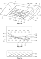
- the openings of the cavities are covered by an air permeable layer 91, such as a fabric layer or wire mesh or perforated screen, as shown in Fig. 3c
- Fig. 3d discloses a perspective Xray view illustrating an example of a serration 43 similar to that shown in Fig. 3 and having a shape tapering as seen from the base portion 47 towards the apex48.
- the serration 43 shown is provided with five resonators, four of the resonators being spiral-shaped with spiral-shaped cavities and one of the resonators being straight having a straight cavity.
- Each of the cavities extend from an opening 55 in the exposed noise reducing surface of the blade to a bottom 57 of the cavity 56 at the base portion 47 of the serration 43.
- the spiral-shaped cavities and the straight cavity have different lengths in order o abate different sound frequencies.
- Fig. 4 is an enlarged diagrammatical view of the encircled area III in Fig. 2 having a second resonator arrangement different from that of Fig. 3 , 3a, 3b, 3c and 3d .
- the noise reducing portion 41 comprising the trailing edge portion 42 having four serrations 43 arranged adjacent to each other such that a valley region 44, is formed between a first and a second adjacent serration of the plurality of serrations.
- the serrated trailing edge may comprise more than four serrations and the trailing edge may be serrated over the entire length thereof.
- the noise reducing portion 41 of the blade is formed by a premanufactured part being integrated in the blade in connection with the manufacturing of the blade.
- the premanufactured noise reducing portion 41 of the blade can be added to a trailing edge 45 of a premanufactured blade 46 as an add-on part.
- the serrated trailing edge or serrated trailing edge portion could also be integrally formed with the blade during the manufacturing thereof.
- Each of the first and second serrations 43 comprises a base portion 47, an apex 48 located downstream of the base portion 47, a first lateral serration side 49 extending between a base portion 47 and the apex 48, a second lateral serration side 50 arranged opposite the first lateral serration side 49 and extending between the base portion 47 and the apex 48, a serration pressure side 51 extending between the base portion 47 the first lateral serration side 49 and the second lateral serration side 50, and a serration suction side 52 arranged opposite the serration pressure side 51 and extending between the base portion 47 of the first lateral serration side 49 and the second lateral serration side 50.
- the serration pressure side 51 can be considered a continuation of and forming a portion of the pressure side 24 of the blade 10, and the serration suction side 52 can be considered a continuation of and forming a portion of the suction side 26 of the blade 10.
- the serration pressure side 51 and the serration suction side 52 can also be considered extending upstream of the base portion 47 of the serrations 43, as the serration suction side 52 upstream of the base portion 47 continues in an upstream suction side bulge portion, such as an upstream tapering suction side bulge portion 54 and the serration pressure side 51 upstream of the base portion 47 continues in an upstream pressure side bulge portion, such as an upstream tapering pressure side bulge portion 53.
- Resonators can be arranged in the pressure side and the suction side upstream of the base portion 47 of the serrations 43.
- the serrations 43 have a tapering shape as seen from the base portion 47 towards the apex 48 and the shape can be at least essentially conical. At least one of the serrations 43 comprises a plurality of acoustic resonators 58, each having a cavity opening 55 in an exposed surface and a cavity 56 having a length L between the opening 55 and the bottom 57 of the cavity 56 opposite the opening 55.
- the opening of the resonators disclosed in the present example is located in the lateral serration sides 49, 50.
- the serration openings may also be arranged in the serration pressure side 51 and/or the serration suction side 52.
- the acoustic resonators are quarter wavelength resonators having an opening 55 and an elongated cavity 56 with the same cross-sectional area and shape.
- the resonators are of the type shown in Fig 6a .
- Two openings 55 are arranged mutually spaced in each of the first and second lateral sides 49, 50 of the at least one serration 43, as seen in the direction from the base portion 47 towards the apex 48 of the serration 43.
- each of the first and second lateral serration sides 49, 50 may comprise several resonators 58 and thereby openings 55, as indicated in Fig. 4c and Fig. 4d .
- the opening 55 of a fifth resonator 58 is arranged in the apex 48 of the serration.
- the elongated cavity 56 of each resonator 58 extends essentially parallel to or slanted relative the local chord.
- the length of the cavities of the resonators is different for obtaining a frequency band appropriate to abate the noise emitted by the adjacent area of the trailing edge.
- Fig. 7 is an enlarged diagrammatical view of the encircled area IV in Fig. 2 and discloses a noise reducing portion 71 comprising a trailing edge portion 72 having four serrations 73, a valley region 74 being formed between adjacent serrations.
- the noise reducing portion 71 of the blade is formed by a premanufactured serrated trailing edge panel configured to be attached to the trailing edge of a premanufactured blade 76 as an add-on part.
- the premanufactured trailing edge panel 71 comprises an attachment section 93 configured for attaching the trailing edge panel 71 to one of the suction side and pressure side or both said sides of the premanufactured blade 76 at the trailing edge thereof.
- the trailing edge panel comprises the serrations 73 extending downstream of the attachment section 93 when the trailing edge panel is attached to the premanufactured blade.
- the premanufactured serrated trailing edge panel coyl also be added to the blade during manufacturing of the blade by arranging the attachment portion 93 of the panel between the two blade halves of the blade during the adhesive connection of the two blade halves.
- Each of the serrations 73 comprises a base portion 77, an apex 48 located downstream of the base portion 77, a first lateral serration side 79 extending between the base portion 77 and the apex 78, a second lateral serration side 80 arranged opposite the first lateral serration side 79 and extending between the base portion 77 and the apex 78, a serration pressure side 81 extending between the base portion 77 the first lateral serration side 79 and the second lateral serration side 80, and a serration a serration suction side 82 arranged opposite the serration pressure side 81 and extending between the base portion 77, the first lateral serration side 79 and the second lateral serration side 80.
- the serrations 76 have a conical shape as seen from the base portion 77 towards the apex 78 and the cross-sectional shape changed from being flat at the base portion 77 to being essentially circular or elliptical at the apex in the example shown.
- the cross-sectional shape of the serrations could also change so that the cross section at the apex was flat, elliptical rectangular with rounded side walls or had any desired cross-section.
- At least one of the serrations 73 comprises a plurality of acoustic resonators 58, each having a cavity opening 55 in an exposed surface and a cavity 56 having a length L between the opening 55 and the bottom 57 of the cavity 56 opposite the opening 55.
- the resonators are of the types shown in Fig. 6a to Fig. 6e or any other type.
- the openings 55 of the resonators 58 are arranged in the serration pressure side, the serration suction side, the first lateral serration side and/or the second lateral serration side.
- the resonators can also extend into the attachment section 93.
- Fig. 5 is a diagrammatical perspective view of an exemplary wind turbine blade according to the present invention, the blade being identical with that shown in Fig. 2 except that the trailing edge does not comprise a serrated portion noise reducing portion with acoustic resonators.
- Fig. 5b and Fig. 5c are top views as seen in the direction of the arrow T in Fig. 5a and a front view as seen in the direction of the arrow F in Fig. 5a , respectively.
- the present exemplary blade has a trailing edge comprising a straight portion, the noise reducing portion 141 comprising acoustic resonators 58 located in a trailing edge region 142 adjacent to or at the trailing edge 20.
- the noise reducing portion 141 of the blade is formed by a premanufactured part being integrated in the blade in connection with the manufacturing of the blade.
- the straight trailing edge portion could also be integrally formed with the blade during the manufacturing thereof.
- the noise reducing portion 141 comprises a plurality of acoustic resonators 58 arranged in an array of rows and columns.
- the resonators 58 shown are quarter wavelength resonators having an opening 55 in the suction side 26 and a cavity 56 being slanted span wise relative to the local chord C for obtaining sufficient length for abating low frequencies.
- Some of the cavities 56 of the resonators 58 have a rectilinear shape and are of the resonator type shown in Fig. 6a , other have an undulated shape for obtaining additional length, and are of the resonator type shown in Fig. 6d .
- the cavities 56 have different lengths between the opening 55 and the bottom 57 for obtaining a frequency band of the noise reducing portion 141 for abating the noise emitted by the adjacent area of the trailing edge of the blade.
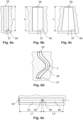
- Fig. 6a illustrates an example of a resonator where the cross-sectional area and shape of the cavity 56 is essentially the same as that of the cavity opening 55.
- the resonator is a quarter wavelength resonator where the length L between the cavity opening 55 and the bottom 57 is larger than the transverse dimension of the cavity 56.
- Fig. 6b illustrates an example of a resonator where the cross-sectional area of the cavity 56 is larger than that of the cavity opening 55 and the cross-sectional area of the cavity 56 is constant over the length of the cavity between the opening 55 and the bottom 57.
- the length L is longer than the transverse dimension of the cavity 56.
- Fig. 6c illustrates an example of a resonator where the cross-sectional area of the cavity 56 is larger than that of the cavity opening 55 and the cross-sectional area of the cavity 56 increases over the length L of the cavity between the opening 55 and the bottom 57.
- the length of the cavity 56 is longer than the transverse dimension thereof.
- Fig. 6d illustrates an example of a resonator having an undulated shape and where the cross-sectional area and shape of the cavity 56 is essentially the same as that of the cavity opening 55.
- the length L of the cavity between the opening 55 and the bottom 57 is longer than the transverse dimension of the cavity.
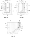
- Fig 6e discloses a resonator having a cavity comprising a transverse partition wall 59 between the bottom 57 and the opening 55 thereof, the partition wall 59 dividing the cavity into an outer cavity part 61 proximal to the cavity opening 55 and an inner cavity part 62 proximal to the cavity bottom 57 and being provided with at least one partition wall opening 60.
- the transverse dimension of the cavity opening is smaller than the transverse dimension of the outer cavity part 61 and the transverse dimension of the partition wall opening 60 is smaller than the transverse dimension of the inner cavity part.
- the outer cavity has a length L1 and the inner cavity has a length L2.
- Fig. 6f illustrates an example of an essentially U-shaped resonator 58 having a U-shaped cavity 56 having a first cavity part 56B and a lower passage 65 between the first and the second cavity part.
- Fig. 6h discloses a resonator arrangement similar to that of Fig. 6f .
- the resonator arrangement shown in Fig. 6h differs from that shown in Fig. 6f in that the shape of the u-Shaped resonator has a different shape than that shown in Fig. 6f in that the second cavity part 56B of the resonator is angled relative to the first cavity part 56A of the resonator and that the bottom wall 63 of the cavity forms the second bottom 64 of a second resonator 66 having a second cavity 67 spaced from the first cavity part 56A of the resonator 58.
- the second cavity 67 is provided with a second opening 68 in the exposed surface of the blade.
Landscapes
- Engineering & Computer Science (AREA)
- Life Sciences & Earth Sciences (AREA)
- Sustainable Development (AREA)
- Sustainable Energy (AREA)
- Chemical & Material Sciences (AREA)
- Combustion & Propulsion (AREA)
- Mechanical Engineering (AREA)
- General Engineering & Computer Science (AREA)
- Physics & Mathematics (AREA)
- Fluid Mechanics (AREA)
- Wind Motors (AREA)
- Soundproofing, Sound Blocking, And Sound Damping (AREA)
Priority Applications (1)
| Application Number | Priority Date | Filing Date | Title |
|---|---|---|---|
| EP25171645.2A EP4567274A3 (en) | 2021-05-06 | 2022-05-03 | Noise reducing wind turbine blade |
Applications Claiming Priority (2)
| Application Number | Priority Date | Filing Date | Title |
|---|---|---|---|
| EP21172504 | 2021-05-06 | ||
| PCT/EP2022/061761 WO2022233815A1 (en) | 2021-05-06 | 2022-05-03 | Noise reducing wind turbine blade |
Related Child Applications (2)
| Application Number | Title | Priority Date | Filing Date |
|---|---|---|---|
| EP25171645.2A Division EP4567274A3 (en) | 2021-05-06 | 2022-05-03 | Noise reducing wind turbine blade |
| EP25171645.2A Division-Into EP4567274A3 (en) | 2021-05-06 | 2022-05-03 | Noise reducing wind turbine blade |
Publications (2)
| Publication Number | Publication Date |
|---|---|
| EP4334585A1 EP4334585A1 (en) | 2024-03-13 |
| EP4334585B1 true EP4334585B1 (en) | 2025-06-25 |
Family
ID=75825680
Family Applications (2)
| Application Number | Title | Priority Date | Filing Date |
|---|---|---|---|
| EP22726737.4A Active EP4334585B1 (en) | 2021-05-06 | 2022-05-03 | Noise reducing wind turbine blade |
| EP25171645.2A Pending EP4567274A3 (en) | 2021-05-06 | 2022-05-03 | Noise reducing wind turbine blade |
Family Applications After (1)
| Application Number | Title | Priority Date | Filing Date |
|---|---|---|---|
| EP25171645.2A Pending EP4567274A3 (en) | 2021-05-06 | 2022-05-03 | Noise reducing wind turbine blade |
Country Status (5)
| Country | Link |
|---|---|
| US (1) | US12276250B2 (da) |
| EP (2) | EP4334585B1 (da) |
| CN (1) | CN117321303A (da) |
| DK (1) | DK4334585T3 (da) |
| WO (1) | WO2022233815A1 (da) |
Family Cites Families (17)
| Publication number | Priority date | Publication date | Assignee | Title |
|---|---|---|---|---|
| DK174319B1 (da) | 2000-06-20 | 2002-12-02 | Lm Glasfiber As | Vindmøllevinge med støjdæmpningsmidler |
| US7059833B2 (en) | 2001-11-26 | 2006-06-13 | Bonus Energy A/S | Method for improvement of the efficiency of a wind turbine rotor |
| US7959412B2 (en) * | 2006-09-29 | 2011-06-14 | General Electric Company | Wind turbine rotor blade with acoustic lining |
| US20100143151A1 (en) * | 2009-02-06 | 2010-06-10 | General Electric Company | Permeable acoustic flap for wind turbine blades |
| WO2011157849A2 (en) * | 2010-06-18 | 2011-12-22 | Suzlon Blade Technology B.V. | Rotor blade for a wind turbine |
| US8083488B2 (en) * | 2010-08-23 | 2011-12-27 | General Electric Company | Blade extension for rotor blade in wind turbine |
| DK2783103T3 (da) * | 2011-11-23 | 2017-04-10 | Lm Wp Patent Holding As | Vindmøllevinge |
| US20150050154A1 (en) * | 2013-05-23 | 2015-02-19 | Kristian R. DIXON | Airfoil trailing edge apparatus for noise reduction |
| WO2014207015A1 (en) * | 2013-06-27 | 2014-12-31 | Siemens Aktiengesellschaft | Rotor blade with noise reduction means |
| WO2015192915A1 (en) | 2014-06-18 | 2015-12-23 | Siemens Aktiengesellschaft | Rotor blade with noise reduction means |
| ES2787608T3 (es) * | 2015-05-29 | 2020-10-16 | Siemens Gamesa Renewable Energy As | Aleta de reducción de ruido con abertura |
| WO2017044099A1 (en) * | 2015-09-10 | 2017-03-16 | Siemens Aktiengesellschaft | Noise reducing fence for a wind turbine blade |
| US10240576B2 (en) * | 2015-11-25 | 2019-03-26 | General Electric Company | Wind turbine noise reduction with acoustically absorbent serrations |
| AU2018274880A1 (en) * | 2018-06-22 | 2020-01-16 | Newsouth Innovations Pty Limited | Rotor blade |
| US10746157B2 (en) * | 2018-08-31 | 2020-08-18 | General Electric Company | Noise reducer for a wind turbine rotor blade having a cambered serration |
| CN109356802B (zh) * | 2018-12-29 | 2019-10-01 | 南京航空航天大学 | 一种具有降噪结构的风力机叶片 |
| CN115126649A (zh) * | 2022-05-30 | 2022-09-30 | 南方海洋科学与工程广东省实验室(广州) | 一种低噪风力发电机叶片 |
-
2022
- 2022-05-03 DK DK22726737.4T patent/DK4334585T3/da active
- 2022-05-03 CN CN202280033950.7A patent/CN117321303A/zh active Pending
- 2022-05-03 EP EP22726737.4A patent/EP4334585B1/en active Active
- 2022-05-03 EP EP25171645.2A patent/EP4567274A3/en active Pending
- 2022-05-03 US US18/286,886 patent/US12276250B2/en active Active
- 2022-05-03 WO PCT/EP2022/061761 patent/WO2022233815A1/en not_active Ceased
Also Published As
| Publication number | Publication date |
|---|---|
| CN117321303A (zh) | 2023-12-29 |
| DK4334585T3 (da) | 2025-09-29 |
| US20240384700A1 (en) | 2024-11-21 |
| US12276250B2 (en) | 2025-04-15 |
| EP4567274A3 (en) | 2025-08-13 |
| EP4567274A2 (en) | 2025-06-11 |
| EP4334585A1 (en) | 2024-03-13 |
| WO2022233815A1 (en) | 2022-11-10 |
Similar Documents
| Publication | Publication Date | Title |
|---|---|---|
| US11268489B2 (en) | Wind turbine noise reduction with acoustically absorbent serrations | |
| KR100917773B1 (ko) | 풍력 발전 플랜트를 위한 회전자 날개 | |
| EP2604856B1 (en) | Wind turbine blade, wind power generation device provided with same, and design method for wind turbine blade | |
| EP2806156B1 (en) | Airfoil trailing edge apparatus for noise reduction | |
| US6733240B2 (en) | Serrated fan blade | |
| CN101307745B (zh) | 风轮叶片和用于减小风轮中噪音的方法 | |
| CN104220745B (zh) | 风力涡轮机叶片 | |
| CN101454564B (zh) | 具有细长叶片的风力涡轮机 | |
| CN101622446B (zh) | 带有设置小翼的转子叶片的风轮机及用于这种转子的叶片 | |
| CN104514690B (zh) | 具有锯齿状延伸部的风轮机转子叶片 | |
| US20150078913A1 (en) | Arrangement to reduce noise emission | |
| JP2010526231A (ja) | 音響特性が可変の音響パネル | |
| US20110150664A1 (en) | Aeroacoustic rotor blade for a wind turbine, and wind turbine equipped therewith | |
| WO2011157849A2 (en) | Rotor blade for a wind turbine | |
| US20180216600A1 (en) | Noise Reducing Fence for a Wind Turbine Blade | |
| US12018638B2 (en) | Wind turbine serrations with upstream extension | |
| KR20220150292A (ko) | 팬 및 팬 블레이드들 | |
| CN110848153B (zh) | 一种带仿生叶片尾缘的轴流通风机及其工作方法 | |
| EP4567274A2 (en) | Noise reducing wind turbine blade | |
| RU2766498C1 (ru) | Роторная лопасть для ветроэнергетической установки и ветроэнергетическая установка | |
| CN110296039A (zh) | 一种风电叶片及具有该风电叶片的风力发电机 | |
| CN120312656A (zh) | 一种叶片结构、轴流风叶、轴流风机及空调器 | |
| EP2851556A1 (en) | Arrangement to reduce noise of a wind turbine rotor blade | |
| JP5433553B2 (ja) | 風車翼およびこれを備えた風力発電装置ならびに風車翼の設計方法 | |
| CN113167218A (zh) | 用于风能设备的转子叶片和风能设备 |
Legal Events
| Date | Code | Title | Description |
|---|---|---|---|
| STAA | Information on the status of an ep patent application or granted ep patent |
Free format text: STATUS: UNKNOWN |
|
| STAA | Information on the status of an ep patent application or granted ep patent |
Free format text: STATUS: THE INTERNATIONAL PUBLICATION HAS BEEN MADE |
|
| PUAI | Public reference made under article 153(3) epc to a published international application that has entered the european phase |
Free format text: ORIGINAL CODE: 0009012 |
|
| STAA | Information on the status of an ep patent application or granted ep patent |
Free format text: STATUS: REQUEST FOR EXAMINATION WAS MADE |
|
| 17P | Request for examination filed |
Effective date: 20231116 |
|
| AK | Designated contracting states |
Kind code of ref document: A1 Designated state(s): AL AT BE BG CH CY CZ DE DK EE ES FI FR GB GR HR HU IE IS IT LI LT LU LV MC MK MT NL NO PL PT RO RS SE SI SK SM TR |
|
| DAX | Request for extension of the european patent (deleted) | ||
| RAV | Requested validation state of the european patent: fee paid |
Extension state: MA Effective date: 20231116 |
|
| GRAP | Despatch of communication of intention to grant a patent |
Free format text: ORIGINAL CODE: EPIDOSNIGR1 |
|
| STAA | Information on the status of an ep patent application or granted ep patent |
Free format text: STATUS: GRANT OF PATENT IS INTENDED |
|
| INTG | Intention to grant announced |
Effective date: 20241223 |
|
| GRAS | Grant fee paid |
Free format text: ORIGINAL CODE: EPIDOSNIGR3 |
|
| GRAA | (expected) grant |
Free format text: ORIGINAL CODE: 0009210 |
|
| STAA | Information on the status of an ep patent application or granted ep patent |
Free format text: STATUS: THE PATENT HAS BEEN GRANTED |
|
| P01 | Opt-out of the competence of the unified patent court (upc) registered |
Free format text: CASE NUMBER: APP_19166/2025 Effective date: 20250422 |
|
| AK | Designated contracting states |
Kind code of ref document: B1 Designated state(s): AL AT BE BG CH CY CZ DE DK EE ES FI FR GB GR HR HU IE IS IT LI LT LU LV MC MK MT NL NO PL PT RO RS SE SI SK SM TR |
|
| REG | Reference to a national code |
Ref country code: GB Ref legal event code: FG4D |
|
| REG | Reference to a national code |
Ref country code: CH Ref legal event code: EP |
|
| REG | Reference to a national code |
Ref country code: CH Ref legal event code: EP |
|
| REG | Reference to a national code |
Ref country code: IE Ref legal event code: FG4D |
|
| REG | Reference to a national code |
Ref country code: DE Ref legal event code: R096 Ref document number: 602022016468 Country of ref document: DE |
|
| REG | Reference to a national code |
Ref country code: DK Ref legal event code: T3 Effective date: 20250923 |
|
| PG25 | Lapsed in a contracting state [announced via postgrant information from national office to epo] |
Ref country code: FI Free format text: LAPSE BECAUSE OF FAILURE TO SUBMIT A TRANSLATION OF THE DESCRIPTION OR TO PAY THE FEE WITHIN THE PRESCRIBED TIME-LIMIT Effective date: 20250625 |
|
| REG | Reference to a national code |
Ref country code: LT Ref legal event code: MG9D |
|
| PG25 | Lapsed in a contracting state [announced via postgrant information from national office to epo] |
Ref country code: NO Free format text: LAPSE BECAUSE OF FAILURE TO SUBMIT A TRANSLATION OF THE DESCRIPTION OR TO PAY THE FEE WITHIN THE PRESCRIBED TIME-LIMIT Effective date: 20250925 Ref country code: GR Free format text: LAPSE BECAUSE OF FAILURE TO SUBMIT A TRANSLATION OF THE DESCRIPTION OR TO PAY THE FEE WITHIN THE PRESCRIBED TIME-LIMIT Effective date: 20250926 |
|
| PG25 | Lapsed in a contracting state [announced via postgrant information from national office to epo] |
Ref country code: BG Free format text: LAPSE BECAUSE OF FAILURE TO SUBMIT A TRANSLATION OF THE DESCRIPTION OR TO PAY THE FEE WITHIN THE PRESCRIBED TIME-LIMIT Effective date: 20250625 |
|
| PG25 | Lapsed in a contracting state [announced via postgrant information from national office to epo] |
Ref country code: HR Free format text: LAPSE BECAUSE OF FAILURE TO SUBMIT A TRANSLATION OF THE DESCRIPTION OR TO PAY THE FEE WITHIN THE PRESCRIBED TIME-LIMIT Effective date: 20250625 |
|
| PG25 | Lapsed in a contracting state [announced via postgrant information from national office to epo] |
Ref country code: RS Free format text: LAPSE BECAUSE OF FAILURE TO SUBMIT A TRANSLATION OF THE DESCRIPTION OR TO PAY THE FEE WITHIN THE PRESCRIBED TIME-LIMIT Effective date: 20250925 |
|
| PG25 | Lapsed in a contracting state [announced via postgrant information from national office to epo] |
Ref country code: LV Free format text: LAPSE BECAUSE OF FAILURE TO SUBMIT A TRANSLATION OF THE DESCRIPTION OR TO PAY THE FEE WITHIN THE PRESCRIBED TIME-LIMIT Effective date: 20250625 |
|
| REG | Reference to a national code |
Ref country code: NL Ref legal event code: MP Effective date: 20250625 |
|
| PG25 | Lapsed in a contracting state [announced via postgrant information from national office to epo] |
Ref country code: NL Free format text: LAPSE BECAUSE OF FAILURE TO SUBMIT A TRANSLATION OF THE DESCRIPTION OR TO PAY THE FEE WITHIN THE PRESCRIBED TIME-LIMIT Effective date: 20250625 |
|
| PG25 | Lapsed in a contracting state [announced via postgrant information from national office to epo] |
Ref country code: PT Free format text: LAPSE BECAUSE OF FAILURE TO SUBMIT A TRANSLATION OF THE DESCRIPTION OR TO PAY THE FEE WITHIN THE PRESCRIBED TIME-LIMIT Effective date: 20251027 |
|
| REG | Reference to a national code |
Ref country code: AT Ref legal event code: MK05 Ref document number: 1806666 Country of ref document: AT Kind code of ref document: T Effective date: 20250625 |
|
| PG25 | Lapsed in a contracting state [announced via postgrant information from national office to epo] |
Ref country code: IS Free format text: LAPSE BECAUSE OF FAILURE TO SUBMIT A TRANSLATION OF THE DESCRIPTION OR TO PAY THE FEE WITHIN THE PRESCRIBED TIME-LIMIT Effective date: 20251025 |
|
| PG25 | Lapsed in a contracting state [announced via postgrant information from national office to epo] |
Ref country code: AT Free format text: LAPSE BECAUSE OF FAILURE TO SUBMIT A TRANSLATION OF THE DESCRIPTION OR TO PAY THE FEE WITHIN THE PRESCRIBED TIME-LIMIT Effective date: 20250625 Ref country code: SM Free format text: LAPSE BECAUSE OF FAILURE TO SUBMIT A TRANSLATION OF THE DESCRIPTION OR TO PAY THE FEE WITHIN THE PRESCRIBED TIME-LIMIT Effective date: 20250625 |
|
| PG25 | Lapsed in a contracting state [announced via postgrant information from national office to epo] |
Ref country code: CZ Free format text: LAPSE BECAUSE OF FAILURE TO SUBMIT A TRANSLATION OF THE DESCRIPTION OR TO PAY THE FEE WITHIN THE PRESCRIBED TIME-LIMIT Effective date: 20250625 |
|
| PG25 | Lapsed in a contracting state [announced via postgrant information from national office to epo] |
Ref country code: PL Free format text: LAPSE BECAUSE OF FAILURE TO SUBMIT A TRANSLATION OF THE DESCRIPTION OR TO PAY THE FEE WITHIN THE PRESCRIBED TIME-LIMIT Effective date: 20250625 |
|
| PG25 | Lapsed in a contracting state [announced via postgrant information from national office to epo] |
Ref country code: EE Free format text: LAPSE BECAUSE OF FAILURE TO SUBMIT A TRANSLATION OF THE DESCRIPTION OR TO PAY THE FEE WITHIN THE PRESCRIBED TIME-LIMIT Effective date: 20250625 |
|
| PG25 | Lapsed in a contracting state [announced via postgrant information from national office to epo] |
Ref country code: SK Free format text: LAPSE BECAUSE OF FAILURE TO SUBMIT A TRANSLATION OF THE DESCRIPTION OR TO PAY THE FEE WITHIN THE PRESCRIBED TIME-LIMIT Effective date: 20250625 |
|
| PG25 | Lapsed in a contracting state [announced via postgrant information from national office to epo] |
Ref country code: ES Free format text: LAPSE BECAUSE OF FAILURE TO SUBMIT A TRANSLATION OF THE DESCRIPTION OR TO PAY THE FEE WITHIN THE PRESCRIBED TIME-LIMIT Effective date: 20250625 |
|
| REG | Reference to a national code |
Ref country code: DE Ref legal event code: R097 Ref document number: 602022016468 Country of ref document: DE |
|
| PG25 | Lapsed in a contracting state [announced via postgrant information from national office to epo] |
Ref country code: IT Free format text: LAPSE BECAUSE OF FAILURE TO SUBMIT A TRANSLATION OF THE DESCRIPTION OR TO PAY THE FEE WITHIN THE PRESCRIBED TIME-LIMIT Effective date: 20250625 |
|
| VS25 | Lapsed in a validation state [announced via postgrant information from nat. office to epo] |
Ref country code: MA Free format text: LAPSE BECAUSE OF FAILURE TO SUBMIT A TRANSLATION OF THE DESCRIPTION OR TO PAY THE FEE WITHIN THE PRESCRIBED TIME-LIMIT Effective date: 20250625 |
|
| PLBE | No opposition filed within time limit |
Free format text: ORIGINAL CODE: 0009261 |
|
| STAA | Information on the status of an ep patent application or granted ep patent |
Free format text: STATUS: NO OPPOSITION FILED WITHIN TIME LIMIT |
|
| REG | Reference to a national code |
Ref country code: CH Ref legal event code: L10 Free format text: ST27 STATUS EVENT CODE: U-0-0-L10-L00 (AS PROVIDED BY THE NATIONAL OFFICE) Effective date: 20260507 |