EP4334623B1 - Fluidkreislauf und verfahren zum verbinden von leitungen eines solchen fluidkreislaufs - Google Patents
Fluidkreislauf und verfahren zum verbinden von leitungen eines solchen fluidkreislaufs Download PDFInfo
- Publication number
- EP4334623B1 EP4334623B1 EP22736294.4A EP22736294A EP4334623B1 EP 4334623 B1 EP4334623 B1 EP 4334623B1 EP 22736294 A EP22736294 A EP 22736294A EP 4334623 B1 EP4334623 B1 EP 4334623B1
- Authority
- EP
- European Patent Office
- Prior art keywords
- connection
- axis
- fluid circuit
- pipe
- linking
- Prior art date
- Legal status (The legal status is an assumption and is not a legal conclusion. Google has not performed a legal analysis and makes no representation as to the accuracy of the status listed.)
- Active
Links
Images



Classifications
-
- F—MECHANICAL ENGINEERING; LIGHTING; HEATING; WEAPONS; BLASTING
- F16—ENGINEERING ELEMENTS AND UNITS; GENERAL MEASURES FOR PRODUCING AND MAINTAINING EFFECTIVE FUNCTIONING OF MACHINES OR INSTALLATIONS; THERMAL INSULATION IN GENERAL
- F16L—PIPES; JOINTS OR FITTINGS FOR PIPES; SUPPORTS FOR PIPES, CABLES OR PROTECTIVE TUBING; MEANS FOR THERMAL INSULATION IN GENERAL
- F16L27/00—Adjustable joints; Joints allowing movement
- F16L27/12—Adjustable joints; Joints allowing movement allowing substantial longitudinal adjustment or movement
- F16L27/127—Adjustable joints; Joints allowing movement allowing substantial longitudinal adjustment or movement with means for locking the longitudinal adjustment or movement in the final mounted position
- F16L27/1273—Adjustable joints; Joints allowing movement allowing substantial longitudinal adjustment or movement with means for locking the longitudinal adjustment or movement in the final mounted position by quick-acting means
-
- F—MECHANICAL ENGINEERING; LIGHTING; HEATING; WEAPONS; BLASTING
- F16—ENGINEERING ELEMENTS AND UNITS; GENERAL MEASURES FOR PRODUCING AND MAINTAINING EFFECTIVE FUNCTIONING OF MACHINES OR INSTALLATIONS; THERMAL INSULATION IN GENERAL
- F16L—PIPES; JOINTS OR FITTINGS FOR PIPES; SUPPORTS FOR PIPES, CABLES OR PROTECTIVE TUBING; MEANS FOR THERMAL INSULATION IN GENERAL
- F16L25/00—Construction or details of pipe joints not provided for in, or of interest apart from, groups F16L13/00 - F16L23/00
- F16L25/12—Joints for pipes being spaced apart axially
-
- F—MECHANICAL ENGINEERING; LIGHTING; HEATING; WEAPONS; BLASTING
- F16—ENGINEERING ELEMENTS AND UNITS; GENERAL MEASURES FOR PRODUCING AND MAINTAINING EFFECTIVE FUNCTIONING OF MACHINES OR INSTALLATIONS; THERMAL INSULATION IN GENERAL
- F16L—PIPES; JOINTS OR FITTINGS FOR PIPES; SUPPORTS FOR PIPES, CABLES OR PROTECTIVE TUBING; MEANS FOR THERMAL INSULATION IN GENERAL
- F16L27/00—Adjustable joints; Joints allowing movement
- F16L27/10—Adjustable joints; Joints allowing movement comprising a flexible connection only
- F16L27/113—Adjustable joints; Joints allowing movement comprising a flexible connection only the ends of the pipe being interconnected by a rigid sleeve
-
- F—MECHANICAL ENGINEERING; LIGHTING; HEATING; WEAPONS; BLASTING
- F16—ENGINEERING ELEMENTS AND UNITS; GENERAL MEASURES FOR PRODUCING AND MAINTAINING EFFECTIVE FUNCTIONING OF MACHINES OR INSTALLATIONS; THERMAL INSULATION IN GENERAL
- F16L—PIPES; JOINTS OR FITTINGS FOR PIPES; SUPPORTS FOR PIPES, CABLES OR PROTECTIVE TUBING; MEANS FOR THERMAL INSULATION IN GENERAL
- F16L27/00—Adjustable joints; Joints allowing movement
- F16L27/12—Adjustable joints; Joints allowing movement allowing substantial longitudinal adjustment or movement
- F16L27/125—Adjustable joints; Joints allowing movement allowing substantial longitudinal adjustment or movement having longitudinal and rotary movement
-
- F—MECHANICAL ENGINEERING; LIGHTING; HEATING; WEAPONS; BLASTING
- F16—ENGINEERING ELEMENTS AND UNITS; GENERAL MEASURES FOR PRODUCING AND MAINTAINING EFFECTIVE FUNCTIONING OF MACHINES OR INSTALLATIONS; THERMAL INSULATION IN GENERAL
- F16L—PIPES; JOINTS OR FITTINGS FOR PIPES; SUPPORTS FOR PIPES, CABLES OR PROTECTIVE TUBING; MEANS FOR THERMAL INSULATION IN GENERAL
- F16L37/00—Couplings of the quick-acting type
- F16L37/08—Couplings of the quick-acting type in which the connection between abutting or axially overlapping ends is maintained by locking members
- F16L37/10—Couplings of the quick-acting type in which the connection between abutting or axially overlapping ends is maintained by locking members using a rotary external sleeve or ring on one part
- F16L37/107—Bayonet-type couplings
Definitions
- the present invention relates to the field of fluid circuits in an aircraft, for example, a drinking water circuit, waste water, drainage, etc.
- the invention also relates to the connection of pipes of such a fluid circuit.
- a fluid circuit comprises a plurality of pipes mechanically and fluidically connected to each other.
- the pipes are independently secured to the structure of the aircraft and then fluidically connected to each other.
- the pipes are not mobile relative to each other but fixed during a connection.
- the pipes are subject to thermal expansion.
- a small axial clearance can be envisaged to take into account relative deformations or displacements between the pipes and the surrounding supporting structure.
- a connecting connector which must be mounted at the interface between the first pipe and the second pipe in order to ensure a sealed connection.
- a first pipe 101 and a second pipe 102 are shown which extend longitudinally along an axis X and which are connected in a sealed manner by a connector 103 capable of translating axially on the first pipe 101 to cooperate with the end of the second pipe 102.
- Each pipe 101, 102 comprises a connection end 111, 121 on which a connection element 112, 122 is mounted.
- the invention thus aims to eliminate at least some of these drawbacks.
- the central sleeve can be conveniently manufactured and then connected to the connecting members at a later stage.
- the flexible teeth allow the central sleeve to be guided while allowing it to be tilted during connection, thereby conveniently compensating for any misalignment.
- the flexible teeth of the central sleeve are distributed circumferentially.
- the cooperation is optimal for any type of misalignment.
- the second connecting member comprises a plurality of flexible teeth configured to cooperate with the second connection end in order to correct a possible misalignment between the first axis and the second axis during the cooperation of the second connecting member with the central sleeve.
- the teeth of the second connecting member also make it possible to compensate for a misalignment. The forces linked to the misalignment are thus distributed optimally to limit the risk of defect and breakage.
- the first connecting member comprises a plurality of flexible teeth configured to cooperate with the first connecting end in order to correct a possible misalignment between the first axis and the second axis during the cooperation of the first connecting member with the central sleeve.
- the flexible teeth are distributed circumferentially.
- the first connecting member comprises a wavy connecting portion connecting the flexible teeth.
- a connecting portion provides flexibility to the teeth and allows movement.
- the first connecting member includes openings, preferably cylindrical, formed in the corrugated connecting portion, for spacing the flexible teeth. In addition to improved flexibility, such openings allow for reduced mechanical stresses in the first connecting member.
- the connecting portion has an outer bend having a first radius of curvature and an inner bend having a second radius of curvature less than the first radius of curvature so as to provide flexibility and damping to compensate for alignment defects without generating stresses.
- each flexible tooth is inclined towards the first axis at an angle of between 2° and 5° in order to ensure progressive contact with the first pipe while limiting assembly efforts.
- the flexible teeth of the second connecting member are distributed circumferentially.
- the first connecting member and the second connecting member are identical. This makes it easier to industrialize.
- the forces applied to the connector are similar at its two ends.
- At least one end of the central sleeve comprises a clamping device configured to cooperate with a connecting member.
- a clamping member makes it possible to achieve axial clamping ensuring the durability of the connection.
- the clamping device comprises at least one guide slot, preferably so as to allow quarter-turn clamping.
- axial clamping is carried out conveniently by guided rotation of a connecting member.
- Bayonet-type clamping is quick and practical.
- the connecting connector comprises a first sealing member and a second sealing member configured to cooperate respectively with the first connection end and the second connection end in the connection position.
- sealing is guaranteed.
- the sealing members have different diameters.
- a draft angle is provided so as to allow it to be removed from the mold.
- the sealing members have different diameters in order to ensure optimum sealing taking into account this draft angle.
- the invention also relates to an aircraft comprising a fluid circuit as presented previously, in which the first pipe and the second pipe are secured to a structure of the aircraft, the connection ends of the pipes being fixed and spaced apart by an axial connection clearance.
- the invention also relates to a method for connecting at least a first pipe and a second pipe by means of a fluid circuit connection connector as presented above, the connection ends of the pipes being fixed and spaced apart by an axial connection clearance, the connection connector extending over a connection end of a pipe, the method comprising a step of moving the central sleeve of the connection connector between the connection ends, the flexible teeth of the central sleeve cooperating with the second peripheral connection element in order to correct any misalignment between the first axis and the second axis.
- the method comprises a step of cooperation of the second connecting member with the central sleeve so as to lock the connecting connector.
- a fluid circuit according to the invention intended for aeronautical use will now be presented, in particular for the transport of fuel, water and oxygen, air, fire-fighting gas, refrigeration, etc.
- the fluid circuit comprises a plurality of pipes that are tuned to each other to guide a fluid.
- the individual pipes are first secured to a structure of an aircraft and then connected to each other.
- the invention will be presented for the connection of two pipes of a fluid circuit.
- the invention also applies to the connection of more than two pipes, in particular, three pipes.
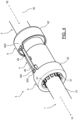
- FIG. 4 there is shown an embodiment of a fluid circuit according to the invention which comprises a first pipe 1, a second pipe 2 and a connecting connector 3 mounted at the interface between the first pipe 1 and the second pipe 2, in order to fluidically connect the first pipe 1 to the second pipe 2.
- each pipe comprises a tubular body which is terminated at each end by a connection end.
- the tubular body of each pipe preferably comprises curved portions so as to allow the fluid circuit to connect different equipment in a practical manner while freeing itself from positioning constraints.
- each pipe defines an inner surface, in contact with the fluid to be conducted, and an outer surface, opposite the inner surface.
- the first pipe 1 comprises a first connection end 11, extending along a first axis X1 and defining an inner surface and an outer surface.
- the first connection end 11 comprises a first connection element 12, in particular, an L-shaped peripheral connection ring.
- the second pipe 2 comprises a second connection end 21, extending along a second axis X2 and defining an inner surface and an outer surface.
- the second connection end 21 comprises a second peripheral connection element 22, in particular, a connection ring.
- the axes X1, X2 are preferably aligned but may be offset by an angular offset of up to 10° or by a vertical/lateral offset of up to 10mm.
- each connecting ring 12, 22 are split rings, more preferably, each connecting ring 12, 22 has an L-shaped section.
- the pipes 1, 2 have similar structures in order to allow industrialization at lower costs.
- the connecting elements 12, 22 could be in other forms, in particular, a crenellated crown or a lug.
- each connecting element 12, 22 has an axial thickness of the order of 2 mm and a radial length of between 4 mm and 8 mm relative to the axis X1, X2.
- the distance between the first connection element 12 and the end edge of the first pipe 1 is greater than the distance between the second connection element 22 and the end edge of the second pipe 2.
- connection end 11, 21 could also be formed by a connection tip which would be mounted in an attached manner with its connection element 21, 22.
- connection ends 11, 21 of the pipes 1, 2 are fixed and spaced by an axial connection clearance Jx, between 5mm and 10mm, which is filled by the movement of the connection connector 3 as will be presented later.
- Each pipe 1, 2 has a tubular body which comprises one or more curved portions.
- the diameter of the tubular body and/or of each connection end is preferably between 12.7 mm and 50.8 mm.
- each pipe 1, 2 is made of plastic material but it goes without saying that other materials could be suitable, for example, a metallic material.
- the connection of connection 3 preferably comprises a metallization in order to ensure electrical conductivity.
- the central sleeve 4, the flexible teeth 41 and the connecting members 5, 6 comprise a metallization, for example, at least one metallization strip.
- the axes X1, X2 are oriented from right to left.
- the connecting connector 3 makes it possible to put the two pipes 1, 2 which are separated into fluid communication.
- the first pipe 1 further comprises a first connecting member 5, free in translation and rotation about the first axis X1, configured to cooperate with a first end of the connecting connector 3.
- the second pipe 2 further comprises a second connecting member 6, free in translation and rotation about the second axis X2, configured to cooperate with a second end of the connecting connector 3.
- the connecting members 5, 6 make it possible to immobilize and secure the position of the connecting connector 3.
- the connecting members 5, 6 are not positioned between the connection elements 12, 22 but outside the latter.
- the connecting members 5, 6 are mounted captively on the connection ends 11, 21 so as to avoid their loss when handling a pipeline 1, 2.
- the first connecting member 5 is mounted to the left of the first connection element 12 while the second connecting member 6 is mounted to the right of the second connection element 22.
- the structure and function of the connecting members 5, 6 will be presented subsequently.
- first connecting member 5 and the central sleeve 4 are pre-assembled on the first pipe 1 while the second connecting member 7 is pre-assembled on the second pipe 2.
- the first connecting member 5 is connected to the central sleeve 4 during pre-assembly, in particular in the workshop, while the second connecting member 6 is connected to the central sleeve 4 in situ, in particular in an aircraft.
- the fluid circuit comprises a connecting connector 3 configured to mechanically connect the two connection ends 11, 21.
- the connecting connector 3 comprises a central sleeve 4, a first sealing member 71, a second sealing member 72, a first spacer 8 and a second spacer 9.
- the central sleeve 4 is configured to extend externally to the connection ends 11, 21 in order to provide a fluid connection between the pipes 1, 2.
- the central sleeve 4 is configured to compress the sealing members 71, 72 in order to provide a seal between the connection ends 11, 21.
- the central sleeve 4 has an internal diameter slightly smaller than that of the sealing members 71, 72 so as to compress them radially.
- the central sleeve 4 is in the form of a peripheral envelope which extends axially along the first axis X1. In the mounted position, the central sleeve 4 is adapted to slide along the first axis X1 on the connection end 11 of the first pipe 1. With reference to the figure 6 , the central sleeve 4 comprises a first portion 4A intended to extend on the side of the first pipe 1 in the locked position and a second portion 4B intended to extend on the side of the second pipe 2 in the locked position.
- the central sleeve 4 comprises, at the second portion 4B, a plurality of flexible teeth 41 configured to cooperate with the second connection element 22 in order to correct a possible misalignment between the first axis X1 and the second axis X2.
- the flexible teeth 41 extend parallel to the first axis X1 and have the same axial position so as to form a crenellated crown.
- each flexible tooth 41 has a length of between 2 mm and 20 mm, in order to allow an angular movement of less than or equal to 10°.
- the flexible teeth 41 are angularly spaced from each other, in particular, in a distributed manner.
- the flexible teeth 41 are radially aligned with the second sealing member 72 so as to allow the flexible radial teeth 41 to move the second sealing member 72 during a longitudinal movement of the central sleeve 4 towards the first pipe 1.
- the central sleeve 4 comprises, at the level of the second portion 4B, a radial crown 42 extending externally to the flexible teeth 41 and advantageously allowing the central connector 4 to be handled without damaging the flexible teeth 41.
- the first portion 4A of the central sleeve 4 is connected to the second portion 4B by a substantially cylindrical sheath 43 in which the sealing members 71, 72 and the spacers 8, 9 are housed.
- the central sleeve 4 comprises, at each portion 4A, 4B, a clamping device 46 configured to cooperate with a connecting member 5, 6.
- each clamping device 46 comprises a plurality of guide slots 47, formed at the periphery of the clamping device 46, to allow axial locking following an angular rotation of a connecting member 5, 6, in particular a quarter-turn clamping.
- other clamping means could be suitable, in particular a screw thread.
- the central sleeve 4 further comprises a first locking member 48 configured to cooperate with the first connecting member 5 and a second locking member 49 configured to cooperate with the second connecting member 6.
- first locking member 48 configured to cooperate with the first connecting member 5
- second locking member 49 configured to cooperate with the second connecting member 6.
- the locking members 48, 49 extend longitudinally along the first axis X1 radially outwardly to the sheath 43.
- the locking members 48, 49 are connected by a radial wall 44 to the sheath 43 allowing each locking member 48, 49 to be able to tilt towards the center of the central sleeve 4 relative to the first axis X1 so as to cooperate with a connecting member 5, 6.
- the locking members 48, 49 respectively comprise at their free ends locking teeth 481, 491 projecting radially outward so as to be able to be inserted into a through-hole of a connecting member 5, 6.
- the central sleeve 4 is a single-piece, i.e. formed from a single piece, which makes it possible to dispense with a mechanical articulation which could wear out or represent a fragile area.
- the central sleeve 4 is made of a plastic material.
- the connecting connector 3 comprises a first sealing member 71 and a second sealing member 72 to ensure sealing with the central sleeve 4 respectively with the first connection end 11 and the second connection end 21.
- Each sealing member 71, 72 has a toric shape and is made of an elastic material.
- the first sealing member 71 has a larger diameter than the second sealing member 72 so as to allow an inclination of the connecting connector 3 relative to the first axis X1.
- the connecting connector 3 comprises a first spacer 8, positioned between the first connection member 11 and the first sealing member 71 and a second spacer 9 positioned longitudinally between the two sealing members 71, 72.
- the first spacer 8 and the second spacer 9 advantageously make it possible to maintain the sealing members 71, 72 and to move them together during a movement of the central sleeve 4.
- the longitudinal ends of the second spacer 9 are curved so as to fit the shape of the sealing members 71, 72 of circular section.
- the connecting members 5, 6 lock the central sleeve 4.
- the connecting members 5, 6 are identical and only the first connecting member 5 will be presented subsequently for the sake of clarity and conciseness.
- the first connecting member 5 comprises a plurality of flexible teeth 51 configured to cooperate with the outer surface of the first pipe 1 in order to correct any misalignment between the first axis X1 and the second axis X2.
- the flexible teeth 51 extend parallel to the first axis X1 and have the same axial position.
- the flexible teeth 51 are substantially similar to the flexible teeth 41 previously presented and are organized to form a crown.
- the flexible teeth 51 are spaced apart by cylindrical openings 54 in order to avoid a concentration of stresses.
- the flexible teeth 51 are connected to an outer annular crown 52 via a connecting portion 53.
- the connecting portion 53 has a corrugated section, preferably S-shaped, so as to increase flexibility and allow relative inclination between the flexible teeth 51 (which align with the first axis X1) and the outer annular crown 52 which aligns with the central sleeve 4 along the second axis X2.
- the openings 54 are formed in the connecting portion 53 configured, on the one hand, to provide an elastic connection in order to resist the stresses and, on the other hand, to ensure sufficient rigidity to allow a realignment of the axes X1, X2.
- the connecting portion 53 has for this purpose a thickness of the order of 1 to 2 mm, an external elbow 53e having a radius of curvature between 2 mm and 3 mm and an internal elbow 53i having a radius of curvature between 1 mm and 2 mm.
- each flexible tooth 51 is inclined towards the axis at an angle of between 2° and 5° so as to come into contact with the outer surface of the first pipe 1 and correct its orientation by stressing the connecting portion 53.
- the outer annular crown 52 comprises a through opening 521 for receiving the locking tooth 481 of the first locking member 48 of the central sleeve 4.
- the outer annular crown 52 further comprises a plurality of inner radial fingers 522, distributed angularly, configured to be guided in the guide slots 47 of the guide device 46 formed on the central sleeve 4 in order to allow axial tightening.
- the second connecting member 6 comprises a plurality of flexible teeth 61 configured to cooperate with the outer surface of the second pipe 2.
- the flexible teeth 61 extend parallel to the second axis X2.
- the connecting connector 3 according to the invention comprises a very limited number of elements in this embodiment, which reduces its cost. Furthermore, advantageously, each element can be produced at low cost, in particular by plastic injection, which in particular reduces its mass.
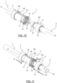
- the connecting connector 3 is pre-assembled at the connection end 11 of the first pipe 1 by means of the first connecting member 5 as illustrated in figure 10 .
- the second connecting member 6 is not connected.
- the sealing members 71, 72 are in contact with the first connection end 11 and the first connecting member 5 is positioned far to the left of the first connection element 12.
- pre-assembly is very advantageous since it avoids an operator having to use add-on elements to connect the two pipes 1, 2.
- the first pipe 1 can thus be easily handled with its connecting connector 3. Indeed, the connecting connector 3 can be directly closed and secured.
- Pre-assembly advantageously allows the connecting connector 3 to be positioned when fixing the pipes 1, 2 to an aircraft structure, which provides a significant time saving. It goes without saying, however, that the connecting connector 3 could be mounted subsequently.
- a method of connecting a first pipe 1 and a second pipe 2 by means of a connecting connector 3 according to one embodiment of the invention will now be presented.
- the pipes 1, 2 have been previously secured to a structure of an aircraft and are not mobile relative to each other.
- connection ends 11, 21 of the pipes 1, 2 are fixed and spaced by an axial connection clearance Jx, the connecting connector 3 is pre-assembled on the connection end 11 of the first pipe 1 as explained previously.
- the method comprises a step of axial displacement E1 of the connecting connector 3 along the first axis X1 until it extends to the interface between the two connection ends 11, 21 of the pipes 1, 2.
- this displacement can be carried out by an operator using only one of his hands, which is practical.
- Such a movement is simple to carry out since the operator only has to move the central sleeve 4 to the right so as to move the first sealing member 71 and the second sealing member 72 to ensure sealing with the first connection end 11 and the second connection end 21 thanks to the spacers 8, 9.
- the flexible teeth 41 of the central sleeve 4 cooperate with the second connection element 22 of the second pipe 2 which extends along the second axis X2.
- any misalignment is compensated by the flexible teeth 41.
- the second connecting member 6 is moved to the left (step E2) so as to cooperate with the central sleeve 4 by quarter-turn screwing (step E3) in order to pull the central sleeve 4 to the right in order to immobilize the connecting connector in a stable manner 3 between the connection elements 12, 22 ( Figure 5 ).
- the locking tooth 491 of the second locking member 4 of the central sleeve 4 cooperates with the through opening 621 of the second connecting member 6.
- the flexible teeth 61 of the second connecting member 6 also make it possible to compensate for alignment defects between the central sleeve 4 and the second pipe 2.
Landscapes
- Engineering & Computer Science (AREA)
- General Engineering & Computer Science (AREA)
- Mechanical Engineering (AREA)
- Quick-Acting Or Multi-Walled Pipe Joints (AREA)
Claims (14)
- Fluidkreislauf, insbesondere für ein Luftfahrzeug, umfassend• mindestens eine erste Leitung (1), die ein ersten Anschlussende (11) umfasst, sich gemäß einer ersten Achse (X1) erstreckt und eine Innenfläche und eine Außenfläche definiert, wobei das erste Anschlussende (11) ein erstes peripheres Anschlusselement (12) sowie ein erstes Verbindungsorgan (5) umfasst, das translatorisch und rotatorisch frei um die erste Achse (X1) ist,• mindestens eine zweite Leitung (2), die ein zweites Anschlussende (12) umfasst, sich gemäß einer zweiten Achse (X2) erstreckt und eine Innenfläche und eine Außenfläche definiert, wobei das zweite Anschlussende (12) ein zweites peripheres Anschlusselement (22) sowie ein zweites Verbindungsorgan (6) umfasst, das translatorisch und rotatorisch frei um die zweite Achse (X2) ist, wobei die Anschlussenden (11, 21) der Leitungen (1, 2) fest und mit einem axialen Verbindungsspiel (Jx) beabstandet sind,• ein Verbindungsstück (3), um die beiden Anschlussenden (11, 21) dicht zu verbinden, umfassend eine mittlere Hülse (4), die eine Umfangshülle aufweist, die geeignet ist, gemäß der zweiten Achse (X2) zu gleiten, wobei die mittlere Hülse (4) ausgelegt ist, um an einem ersten Ende mit dem ersten Verbindungsorgan (5) und an einem zweiten Ende mit dem zweiten Verbindungsorgan (6) zusammenzuwirken, dadurch gekennzeichnet, dass die mittlere Hülse (4) eine Vielzahl flexibler Zähne (41) aufweist, die ausgelegt sind, um mit dem zweiten peripheren Anschlusselement (22) zusammenzuwirken, um eine mögliche Fehlausrichtung zwischen der ersten Achse (X1) und der zweiten Achse (X2) zu korrigieren.
- Fluidkreislauf nach Anspruch 1, wobei die flexiblen Zähne (41) der mittleren Hülse (4) umfangmäßig verteilt sind.
- Fluidkreislauf nach einem der Ansprüche 1 bis 2, wobei das erste Verbindungsorgan (5) eine Vielzahl flexibler Zähne (51) aufweist, die ausgelegt sind, um mit dem ersten Anschlussende (11) zusammenzuwirken, um eine mögliche Fehlausrichtung zwischen der ersten Achse (X1) und der zweiten Achse (X2) beim Zusammenwirken des ersten Verbindungsorgans (5) mit der mittleren Hülse (4) zu korrigieren.
- Fluidkreislauf nach einem der Ansprüche 1 bis 3, wobei das erste Verbindungsorgan (5) einen gewellten Verbindungsabschnitt (53) aufweist, der die flexiblen Zähne (51) verbindet.
- Fluidkreislauf nach Anspruch 4, wobei das erste Verbindungsorgan (5) Öffnungen (54) aufweist, vorzugsweise zylindrisch, die in dem gewellten Verbindungsabschnitt (53) ausgebildet sind, um die flexiblen Zähne (51) zu beabstanden.
- Fluidkreislauf nach einem der Ansprüche 4 bis 5, wobei der Verbindungsabschnitt (53) eine äußere Biegung (53e) mit einem ersten Krümmungsradius und eine innere Biegung (53i) mit einem zweiten Krümmungsradius aufweist, der kleiner als der erste Krümmungsradius ist.
- Fluidkreislauf nach einem der Ansprüche 3 bis 6, wobei jeder flexible Zahn (51) in Richtung der ersten Achse (X1) in einem Winkel zwischen 2° und 5° geneigt ist.
- Fluidkreislauf nach einem der Ansprüche 1 bis 7, wobei das erste Verbindungsorgan (5) und das zweite Verbindungsorgan (6) identisch sind.
- Fluidkreislauf nach einem der Ansprüche 1 bis 8, wobei mindestens ein Ende der mittleren Hülse (4) eine Klemmvorrichtung (46) aufweist, die ausgelegt ist, um mit einem Verbindungsorgan (5, 6) zusammenzuwirken.
- Fluidkreislauf nach einem der Ansprüche 1 bis 9, wobei die Klemmvorrichtung (46) mindestens einen Führungsschlitz aufweist, vorzugsweise derart, dass eine Klemmung um eine Vierteldrehung ermöglicht wird.
- Fluidkreislauf nach einem der Ansprüche 1 bis 10, wobei das Verbindungsstück (3) ein erstes Dichtungsorgan (71) und ein zweites Dichtungsorgan (72) aufweist, die ausgelegt sind, um in Verbindungsposition jeweils mit dem ersten Anschlussende (11) und dem zweiten Anschlussende (21) zusammenzuwirken.
- Luftfahrzeug, aufweisend einen Fluidkreislauf nach einem der Ansprüche 1 bis 11, wobei die erste Leitung (1) und die zweite Leitung (2) fest mit einer Struktur des Luftfahrzeugs verbunden sind, wobei die Anschlussenden (11, 21) der Leitungen (1, 2) fest und mit einem axialen Verbindungsspiel (Jx) beabstandet sind.
- Verfahren zum Verbinden mindestens einer ersten Leitung (1) und einer zweiten Leitung (2) mittels eines Verbindungsstücks (3) eines Fluidkreislaufs nach einem der Ansprüche 1 bis 11, wobei die Anschlussenden (11, 21) der Leitungen (1, 2) fest und mit einem axialen Verbindungsspiel (Jx) beabstandet sind, wobei sich das Verbindungsstück (3) über ein Anschlussende (11, 21) einer Leitung (1, 2) erstreckt, wobei das Verfahren umfasst:- einen Schritt des Verlagerns (E1) der mittleren Hülse (4) des Verbindungsstücks (3) zwischen den Anschlussenden (11, 21), wobei die flexiblen Zähne (41) der mittleren Hülse (4) mit dem zweiten peripheren Anschlusselement (22) zusammenwirken, um eine mögliche Fehlausrichtung zwischen der ersten Achse (X1) und der zweiten Achse (X2) zu korrigieren.
- Verbindungsverfahren nach Anspruch 13, umfassend einen Schritt des Zusammenwirkens (E3) des zweiten Verbindungsorgans (6) mit der mittleren Hülse (4), um das Verbindungsstück (3) zu verriegeln.
Applications Claiming Priority (2)
| Application Number | Priority Date | Filing Date | Title |
|---|---|---|---|
| FR2107360A FR3125102B1 (fr) | 2021-07-07 | 2021-07-07 | Circuit de fluide et procédé de raccordement de canalisations d’un tel circuit de fluide |
| PCT/EP2022/068375 WO2023280741A1 (fr) | 2021-07-07 | 2022-07-04 | Circuit de fluide et procédé de raccordement de canalisations d'un tel circuit de fluide |
Publications (2)
| Publication Number | Publication Date |
|---|---|
| EP4334623A1 EP4334623A1 (de) | 2024-03-13 |
| EP4334623B1 true EP4334623B1 (de) | 2025-01-29 |
Family
ID=77180257
Family Applications (1)
| Application Number | Title | Priority Date | Filing Date |
|---|---|---|---|
| EP22736294.4A Active EP4334623B1 (de) | 2021-07-07 | 2022-07-04 | Fluidkreislauf und verfahren zum verbinden von leitungen eines solchen fluidkreislaufs |
Country Status (5)
| Country | Link |
|---|---|
| US (1) | US20240280198A1 (de) |
| EP (1) | EP4334623B1 (de) |
| CA (1) | CA3220249A1 (de) |
| FR (1) | FR3125102B1 (de) |
| WO (1) | WO2023280741A1 (de) |
Families Citing this family (4)
| Publication number | Priority date | Publication date | Assignee | Title |
|---|---|---|---|---|
| US12663104B2 (en) * | 2024-04-02 | 2026-06-23 | Hubbell Incorporated | Chamfer ring for pipe coupling |
| CN118208615B (zh) * | 2024-05-22 | 2024-07-12 | 浙江医药工业设计院有限公司 | 一种用于无菌车间的管道连接密封装置 |
| US12498066B1 (en) * | 2024-06-12 | 2025-12-16 | Ho Sing Enterprises Co., Ltd. | Quick connector structure of fluid shock absorber |
| US20250389362A1 (en) * | 2024-06-24 | 2025-12-25 | Goodrich Corporation | Potted cavity fitting |
Family Cites Families (13)
| Publication number | Priority date | Publication date | Assignee | Title |
|---|---|---|---|---|
| US96962A (en) * | 1869-11-16 | Improved coupling for hollow shafts | ||
| FR383257A (fr) * | 1907-10-24 | 1908-03-02 | Francois Sudre | Joint étanche et articulé pour tuyaux de toute sorte |
| GB207372A (en) * | 1922-11-17 | 1923-11-29 | Irma Pauline Sainrapt | Improvements in or relating to joints for ferro-concrete & other pipes |
| US1833319A (en) * | 1929-07-25 | 1931-11-24 | Fred H Bedford Jr | Flexible pipe coupling |
| US3596934A (en) * | 1969-05-06 | 1971-08-03 | Herbert A De Cenzo | Flexible fluidtight coupling for tubes |
| US3776579A (en) * | 1971-03-11 | 1973-12-04 | Stanley Aviation Corp | Coupling assemblies |
| CH604067A5 (en) * | 1976-02-13 | 1978-08-31 | Schweizer E Esco & Co | Pipe union using short connecting pipe |
| US5595368A (en) * | 1994-08-12 | 1997-01-21 | Bogdany; Arthur | Apparatus for preventing slippage in pipe couplings |
| AU2007293396B2 (en) * | 2006-09-06 | 2012-07-12 | Victaulic Company | Banded flexible pipe coupling |
| US9303804B2 (en) * | 2013-03-12 | 2016-04-05 | Sioux Chief Mfg. Co., Inc. | Combination glue hub and mechanical coupler for pipe fittings |
| EP2827042A1 (de) * | 2013-07-15 | 2015-01-21 | Siemens Aktiengesellschaft | Rohrverbindung zur Durchleitung eines unter Druck stehenden Fluids |
| FR3082587B1 (fr) * | 2018-06-19 | 2020-11-27 | Stelia Aerospace | Circuit de fluide, en particulier pour aeronef, comprenant une premiere canalisation, une deuxieme canalisation et un raccord de liaison |
| FR3102529B1 (fr) * | 2019-10-28 | 2021-10-15 | Stelia Aerospace | Circuit de fluide, en particulier pour aéronef, comprenant une première canalisation, une deuxième canalisation et un raccord de liaison |
-
2021
- 2021-07-07 FR FR2107360A patent/FR3125102B1/fr active Active
-
2022
- 2022-07-04 EP EP22736294.4A patent/EP4334623B1/de active Active
- 2022-07-04 CA CA3220249A patent/CA3220249A1/fr active Pending
- 2022-07-04 WO PCT/EP2022/068375 patent/WO2023280741A1/fr not_active Ceased
- 2022-07-04 US US18/571,581 patent/US20240280198A1/en active Pending
Also Published As
| Publication number | Publication date |
|---|---|
| EP4334623A1 (de) | 2024-03-13 |
| FR3125102A1 (fr) | 2023-01-13 |
| WO2023280741A1 (fr) | 2023-01-12 |
| CA3220249A1 (fr) | 2023-01-12 |
| US20240280198A1 (en) | 2024-08-22 |
| FR3125102B1 (fr) | 2023-06-16 |
Similar Documents
| Publication | Publication Date | Title |
|---|---|---|
| EP4334623A1 (de) | Fluidkreislauf und verfahren zum verbinden von leitungen eines solchen fluidkreislaufs | |
| EP2878873B1 (de) | Patronenartige schnellkupplungsvorrichtung | |
| EP1273843B1 (de) | Wiederverwendbare Kupplung zum Verbinden von verstärkten Schlauchenden | |
| FR2930904A1 (fr) | Assemblage de raccord rapide et outil de degagement | |
| EP3194828B1 (de) | Verbindungsvorrichtung und -verfahren für abgeschrägte rohre | |
| EP0621432B1 (de) | Vorrichtung zum dichten Verbinden eines Schlauches mit einem starren Rohrende | |
| EP3356718B1 (de) | Fluidkreislauf sowie dessen herstellungsverfahren | |
| EP4051939B1 (de) | Fluidkreislauf, insbesondere für ein flugzeug, mit einem ersten rohr, einem zweiten rohr und einer kupplung | |
| EP4108968B1 (de) | Anschlussvorrichtung für fluide mit einsetzbarem rückschlagventil für fahrzeuge | |
| FR3075083A1 (fr) | Outil et procede d'installation d'un joint d'etancheite en permettant une pre-compression pour assembler deux pieces tubulaires | |
| EP2425170B1 (de) | System zur befestigung eines verbinders für ein fluidtransportrohr an einer wand | |
| EP4042050B1 (de) | Flüssigkeitskreislauf mit einer anschlussarmatur für rohre, mit einem führungselement für einen heizkanal | |
| EP1090245B1 (de) | Anordnungsverfahren zum verbinden einer armatur mit einem rohrelement und ein neuer typ kupplung zur duerchführung des verfahrens | |
| FR2846070A1 (fr) | Dispositif de raccordement de deux tubes possedant une extremite evasee | |
| FR3094772A1 (fr) | Dispositif d’assemblage de deux conduits, ligne de circulation fluidique et véhicule comportant un tel dispositif | |
| EP3803177B1 (de) | Verfahren zur herstellung eines flüssigkeitskreislaufs mit einem verbindungsstück mit einer schrägen anschlagfläche | |
| FR2929642A1 (fr) | Tube d'alimentation en lubrifiant d'un turbocompresseur. | |
| EP4536420B1 (de) | Führungsvorrichtung und verfahren zum befüllen eines doppelwandigen rohres mit einem körnigen material zu dessen biegung | |
| EP4196713B1 (de) | Fluidleitung für luftfahrzeug, umfassend ein thermoplastisches rohr und einen steckverbinder | |
| FR2591308A1 (fr) | Adaptateur ajustable, notamment pour elements de canalisations | |
| FR3082587A1 (fr) | Circuit de fluide, en particulier pour aeronef, comprenant une premiere canalisation, une deuxieme canalisation et un raccord de liaison | |
| FR3152851A1 (fr) | Circuit de fluide comprenant un raccord de liaison et procédé associé | |
| WO2025051698A1 (fr) | Circuit de fluide comprenant un raccord de liaison pour canalisations double paroi et procédé associé | |
| WO2025051708A1 (fr) | Mandrin pour machine de cintrage d'une canalisation double paroi, machine de cintrage et procédé associés | |
| FR3104229A1 (fr) | Circuit de fluide comprenant un raccord de liaison pour canalisations |
Legal Events
| Date | Code | Title | Description |
|---|---|---|---|
| STAA | Information on the status of an ep patent application or granted ep patent |
Free format text: STATUS: UNKNOWN |
|
| STAA | Information on the status of an ep patent application or granted ep patent |
Free format text: STATUS: THE INTERNATIONAL PUBLICATION HAS BEEN MADE |
|
| PUAI | Public reference made under article 153(3) epc to a published international application that has entered the european phase |
Free format text: ORIGINAL CODE: 0009012 |
|
| STAA | Information on the status of an ep patent application or granted ep patent |
Free format text: STATUS: REQUEST FOR EXAMINATION WAS MADE |
|
| 17P | Request for examination filed |
Effective date: 20231207 |
|
| AK | Designated contracting states |
Kind code of ref document: A1 Designated state(s): AL AT BE BG CH CY CZ DE DK EE ES FI FR GB GR HR HU IE IS IT LI LT LU LV MC MK MT NL NO PL PT RO RS SE SI SK SM TR |
|
| DAV | Request for validation of the european patent (deleted) | ||
| DAX | Request for extension of the european patent (deleted) | ||
| GRAP | Despatch of communication of intention to grant a patent |
Free format text: ORIGINAL CODE: EPIDOSNIGR1 |
|
| STAA | Information on the status of an ep patent application or granted ep patent |
Free format text: STATUS: GRANT OF PATENT IS INTENDED |
|
| INTG | Intention to grant announced |
Effective date: 20241029 |
|
| GRAS | Grant fee paid |
Free format text: ORIGINAL CODE: EPIDOSNIGR3 |
|
| GRAA | (expected) grant |
Free format text: ORIGINAL CODE: 0009210 |
|
| STAA | Information on the status of an ep patent application or granted ep patent |
Free format text: STATUS: THE PATENT HAS BEEN GRANTED |
|
| AK | Designated contracting states |
Kind code of ref document: B1 Designated state(s): AL AT BE BG CH CY CZ DE DK EE ES FI FR GB GR HR HU IE IS IT LI LT LU LV MC MK MT NL NO PL PT RO RS SE SI SK SM TR |
|
| REG | Reference to a national code |
Ref country code: GB Ref legal event code: FG4D Free format text: NOT ENGLISH |
|
| REG | Reference to a national code |
Ref country code: CH Ref legal event code: EP |
|
| REG | Reference to a national code |
Ref country code: DE Ref legal event code: R096 Ref document number: 602022010247 Country of ref document: DE |
|
| REG | Reference to a national code |
Ref country code: IE Ref legal event code: FG4D Free format text: LANGUAGE OF EP DOCUMENT: FRENCH |
|
| P01 | Opt-out of the competence of the unified patent court (upc) registered |
Free format text: CASE NUMBER: APP_7133/2025 Effective date: 20250212 |
|
| REG | Reference to a national code |
Ref country code: NL Ref legal event code: MP Effective date: 20250129 |
|
| PG25 | Lapsed in a contracting state [announced via postgrant information from national office to epo] |
Ref country code: NL Free format text: LAPSE BECAUSE OF FAILURE TO SUBMIT A TRANSLATION OF THE DESCRIPTION OR TO PAY THE FEE WITHIN THE PRESCRIBED TIME-LIMIT Effective date: 20250129 |
|
| PG25 | Lapsed in a contracting state [announced via postgrant information from national office to epo] |
Ref country code: RS Free format text: LAPSE BECAUSE OF FAILURE TO SUBMIT A TRANSLATION OF THE DESCRIPTION OR TO PAY THE FEE WITHIN THE PRESCRIBED TIME-LIMIT Effective date: 20250429 |
|
| PG25 | Lapsed in a contracting state [announced via postgrant information from national office to epo] |
Ref country code: FI Free format text: LAPSE BECAUSE OF FAILURE TO SUBMIT A TRANSLATION OF THE DESCRIPTION OR TO PAY THE FEE WITHIN THE PRESCRIBED TIME-LIMIT Effective date: 20250129 |
|
| PG25 | Lapsed in a contracting state [announced via postgrant information from national office to epo] |
Ref country code: PL Free format text: LAPSE BECAUSE OF FAILURE TO SUBMIT A TRANSLATION OF THE DESCRIPTION OR TO PAY THE FEE WITHIN THE PRESCRIBED TIME-LIMIT Effective date: 20250129 |
|
| PG25 | Lapsed in a contracting state [announced via postgrant information from national office to epo] |
Ref country code: ES Free format text: LAPSE BECAUSE OF FAILURE TO SUBMIT A TRANSLATION OF THE DESCRIPTION OR TO PAY THE FEE WITHIN THE PRESCRIBED TIME-LIMIT Effective date: 20250129 |
|
| REG | Reference to a national code |
Ref country code: LT Ref legal event code: MG9D |
|
| PG25 | Lapsed in a contracting state [announced via postgrant information from national office to epo] |
Ref country code: IS Free format text: LAPSE BECAUSE OF FAILURE TO SUBMIT A TRANSLATION OF THE DESCRIPTION OR TO PAY THE FEE WITHIN THE PRESCRIBED TIME-LIMIT Effective date: 20250529 Ref country code: NO Free format text: LAPSE BECAUSE OF FAILURE TO SUBMIT A TRANSLATION OF THE DESCRIPTION OR TO PAY THE FEE WITHIN THE PRESCRIBED TIME-LIMIT Effective date: 20250429 |
|
| REG | Reference to a national code |
Ref country code: AT Ref legal event code: MK05 Ref document number: 1763744 Country of ref document: AT Kind code of ref document: T Effective date: 20250129 |
|
| PG25 | Lapsed in a contracting state [announced via postgrant information from national office to epo] |
Ref country code: HR Free format text: LAPSE BECAUSE OF FAILURE TO SUBMIT A TRANSLATION OF THE DESCRIPTION OR TO PAY THE FEE WITHIN THE PRESCRIBED TIME-LIMIT Effective date: 20250129 |
|
| PG25 | Lapsed in a contracting state [announced via postgrant information from national office to epo] |
Ref country code: LV Free format text: LAPSE BECAUSE OF FAILURE TO SUBMIT A TRANSLATION OF THE DESCRIPTION OR TO PAY THE FEE WITHIN THE PRESCRIBED TIME-LIMIT Effective date: 20250129 Ref country code: PT Free format text: LAPSE BECAUSE OF FAILURE TO SUBMIT A TRANSLATION OF THE DESCRIPTION OR TO PAY THE FEE WITHIN THE PRESCRIBED TIME-LIMIT Effective date: 20250529 |
|
| PG25 | Lapsed in a contracting state [announced via postgrant information from national office to epo] |
Ref country code: BG Free format text: LAPSE BECAUSE OF FAILURE TO SUBMIT A TRANSLATION OF THE DESCRIPTION OR TO PAY THE FEE WITHIN THE PRESCRIBED TIME-LIMIT Effective date: 20250129 Ref country code: GR Free format text: LAPSE BECAUSE OF FAILURE TO SUBMIT A TRANSLATION OF THE DESCRIPTION OR TO PAY THE FEE WITHIN THE PRESCRIBED TIME-LIMIT Effective date: 20250430 |
|
| PG25 | Lapsed in a contracting state [announced via postgrant information from national office to epo] |
Ref country code: AT Free format text: LAPSE BECAUSE OF FAILURE TO SUBMIT A TRANSLATION OF THE DESCRIPTION OR TO PAY THE FEE WITHIN THE PRESCRIBED TIME-LIMIT Effective date: 20250129 |
|
| PG25 | Lapsed in a contracting state [announced via postgrant information from national office to epo] |
Ref country code: SE Free format text: LAPSE BECAUSE OF FAILURE TO SUBMIT A TRANSLATION OF THE DESCRIPTION OR TO PAY THE FEE WITHIN THE PRESCRIBED TIME-LIMIT Effective date: 20250129 |
|
| PG25 | Lapsed in a contracting state [announced via postgrant information from national office to epo] |
Ref country code: SM Free format text: LAPSE BECAUSE OF FAILURE TO SUBMIT A TRANSLATION OF THE DESCRIPTION OR TO PAY THE FEE WITHIN THE PRESCRIBED TIME-LIMIT Effective date: 20250129 |
|
| PG25 | Lapsed in a contracting state [announced via postgrant information from national office to epo] |
Ref country code: DK Free format text: LAPSE BECAUSE OF FAILURE TO SUBMIT A TRANSLATION OF THE DESCRIPTION OR TO PAY THE FEE WITHIN THE PRESCRIBED TIME-LIMIT Effective date: 20250129 |
|
| PGFP | Annual fee paid to national office [announced via postgrant information from national office to epo] |
Ref country code: DE Payment date: 20250722 Year of fee payment: 4 |
|
| PG25 | Lapsed in a contracting state [announced via postgrant information from national office to epo] |
Ref country code: IT Free format text: LAPSE BECAUSE OF FAILURE TO SUBMIT A TRANSLATION OF THE DESCRIPTION OR TO PAY THE FEE WITHIN THE PRESCRIBED TIME-LIMIT Effective date: 20250129 |
|
| PG25 | Lapsed in a contracting state [announced via postgrant information from national office to epo] |
Ref country code: EE Free format text: LAPSE BECAUSE OF FAILURE TO SUBMIT A TRANSLATION OF THE DESCRIPTION OR TO PAY THE FEE WITHIN THE PRESCRIBED TIME-LIMIT Effective date: 20250129 Ref country code: CZ Free format text: LAPSE BECAUSE OF FAILURE TO SUBMIT A TRANSLATION OF THE DESCRIPTION OR TO PAY THE FEE WITHIN THE PRESCRIBED TIME-LIMIT Effective date: 20250129 |
|
| PG25 | Lapsed in a contracting state [announced via postgrant information from national office to epo] |
Ref country code: RO Free format text: LAPSE BECAUSE OF FAILURE TO SUBMIT A TRANSLATION OF THE DESCRIPTION OR TO PAY THE FEE WITHIN THE PRESCRIBED TIME-LIMIT Effective date: 20250129 |
|
| PG25 | Lapsed in a contracting state [announced via postgrant information from national office to epo] |
Ref country code: SK Free format text: LAPSE BECAUSE OF FAILURE TO SUBMIT A TRANSLATION OF THE DESCRIPTION OR TO PAY THE FEE WITHIN THE PRESCRIBED TIME-LIMIT Effective date: 20250129 |
|
| REG | Reference to a national code |
Ref country code: DE Ref legal event code: R097 Ref document number: 602022010247 Country of ref document: DE |
|
| PLBE | No opposition filed within time limit |
Free format text: ORIGINAL CODE: 0009261 |
|
| STAA | Information on the status of an ep patent application or granted ep patent |
Free format text: STATUS: NO OPPOSITION FILED WITHIN TIME LIMIT |
|
| REG | Reference to a national code |
Ref country code: CH Ref legal event code: L10 Free format text: ST27 STATUS EVENT CODE: U-0-0-L10-L00 (AS PROVIDED BY THE NATIONAL OFFICE) Effective date: 20251210 |
|
| 26N | No opposition filed |
Effective date: 20251030 |
|
| REG | Reference to a national code |
Ref country code: CH Ref legal event code: H13 Free format text: ST27 STATUS EVENT CODE: U-0-0-H10-H13 (AS PROVIDED BY THE NATIONAL OFFICE) Effective date: 20260224 |
|
| PG25 | Lapsed in a contracting state [announced via postgrant information from national office to epo] |
Ref country code: LU Free format text: LAPSE BECAUSE OF NON-PAYMENT OF DUE FEES Effective date: 20250704 |
|
| REG | Reference to a national code |
Ref country code: BE Ref legal event code: MM Effective date: 20250731 |
|
| PG25 | Lapsed in a contracting state [announced via postgrant information from national office to epo] |
Ref country code: BE Free format text: LAPSE BECAUSE OF NON-PAYMENT OF DUE FEES Effective date: 20250731 |
|
| PG25 | Lapsed in a contracting state [announced via postgrant information from national office to epo] |
Ref country code: CH Free format text: LAPSE BECAUSE OF NON-PAYMENT OF DUE FEES Effective date: 20250731 |
|
| PG25 | Lapsed in a contracting state [announced via postgrant information from national office to epo] |
Ref country code: LT Free format text: LAPSE BECAUSE OF FAILURE TO SUBMIT A TRANSLATION OF THE DESCRIPTION OR TO PAY THE FEE WITHIN THE PRESCRIBED TIME-LIMIT Effective date: 20250129 |
|
| PG25 | Lapsed in a contracting state [announced via postgrant information from national office to epo] |
Ref country code: IE Free format text: LAPSE BECAUSE OF NON-PAYMENT OF DUE FEES Effective date: 20250704 |
|
| PG25 | Lapsed in a contracting state [announced via postgrant information from national office to epo] |
Ref country code: MC Free format text: LAPSE BECAUSE OF FAILURE TO SUBMIT A TRANSLATION OF THE DESCRIPTION OR TO PAY THE FEE WITHIN THE PRESCRIBED TIME-LIMIT Effective date: 20250129 |
|
| PGFP | Annual fee paid to national office [announced via postgrant information from national office to epo] |
Ref country code: FR Payment date: 20260618 Year of fee payment: 5 |
|
| PG25 | Lapsed in a contracting state [announced via postgrant information from national office to epo] |
Ref country code: CY Free format text: LAPSE BECAUSE OF FAILURE TO SUBMIT A TRANSLATION OF THE DESCRIPTION OR TO PAY THE FEE WITHIN THE PRESCRIBED TIME-LIMIT Effective date: 20250129 |