EP4334643B1 - Regelverfahren eines vormischgasbrenners sowie steuer- und regeleinrichtung zur durchführung des verfahrens - Google Patents
Regelverfahren eines vormischgasbrenners sowie steuer- und regeleinrichtung zur durchführung des verfahrens Download PDFInfo
- Publication number
- EP4334643B1 EP4334643B1 EP22715396.2A EP22715396A EP4334643B1 EP 4334643 B1 EP4334643 B1 EP 4334643B1 EP 22715396 A EP22715396 A EP 22715396A EP 4334643 B1 EP4334643 B1 EP 4334643B1
- Authority
- EP
- European Patent Office
- Prior art keywords
- burner
- sensor
- fuel gas
- duct
- air
- Prior art date
- Legal status (The legal status is an assumption and is not a legal conclusion. Google has not performed a legal analysis and makes no representation as to the accuracy of the status listed.)
- Active
Links
Images

Classifications
-
- F—MECHANICAL ENGINEERING; LIGHTING; HEATING; WEAPONS; BLASTING
- F23—COMBUSTION APPARATUS; COMBUSTION PROCESSES
- F23D—BURNERS
- F23D14/00—Burners for combustion of a gas, e.g. of a gas stored under pressure as a liquid
- F23D14/46—Details
- F23D14/60—Devices for simultaneous control of gas and combustion air
-
- F—MECHANICAL ENGINEERING; LIGHTING; HEATING; WEAPONS; BLASTING
- F23—COMBUSTION APPARATUS; COMBUSTION PROCESSES
- F23N—REGULATING OR CONTROLLING COMBUSTION
- F23N1/00—Regulating fuel supply
- F23N1/02—Regulating fuel supply conjointly with air supply
-
- F—MECHANICAL ENGINEERING; LIGHTING; HEATING; WEAPONS; BLASTING
- F23—COMBUSTION APPARATUS; COMBUSTION PROCESSES
- F23D—BURNERS
- F23D14/00—Burners for combustion of a gas, e.g. of a gas stored under pressure as a liquid
- F23D14/02—Premix gas burners, i.e. in which gaseous fuel is mixed with combustion air upstream of the combustion zone
-
- F—MECHANICAL ENGINEERING; LIGHTING; HEATING; WEAPONS; BLASTING
- F23—COMBUSTION APPARATUS; COMBUSTION PROCESSES
- F23D—BURNERS
- F23D14/00—Burners for combustion of a gas, e.g. of a gas stored under pressure as a liquid
- F23D14/34—Burners specially adapted for use with means for pressurising the gaseous fuel or the combustion air
-
- F—MECHANICAL ENGINEERING; LIGHTING; HEATING; WEAPONS; BLASTING
- F23—COMBUSTION APPARATUS; COMBUSTION PROCESSES
- F23N—REGULATING OR CONTROLLING COMBUSTION
- F23N5/00—Systems for controlling combustion
- F23N5/02—Systems for controlling combustion using devices responsive to thermal changes or to thermal expansion of a medium
- F23N5/08—Systems for controlling combustion using devices responsive to thermal changes or to thermal expansion of a medium using light-sensitive elements
-
- F—MECHANICAL ENGINEERING; LIGHTING; HEATING; WEAPONS; BLASTING
- F23—COMBUSTION APPARATUS; COMBUSTION PROCESSES
- F23N—REGULATING OR CONTROLLING COMBUSTION
- F23N5/00—Systems for controlling combustion
- F23N5/02—Systems for controlling combustion using devices responsive to thermal changes or to thermal expansion of a medium
- F23N5/10—Systems for controlling combustion using devices responsive to thermal changes or to thermal expansion of a medium using thermocouples
-
- F—MECHANICAL ENGINEERING; LIGHTING; HEATING; WEAPONS; BLASTING
- F23—COMBUSTION APPARATUS; COMBUSTION PROCESSES
- F23C—METHODS OR APPARATUS FOR COMBUSTION USING FLUID FUEL OR SOLID FUEL SUSPENDED IN A CARRIER GAS OR AIR
- F23C2900/00—Special features of, or arrangements for combustion apparatus using fluid fuels or solid fuels suspended in air; Combustion processes therefor
- F23C2900/9901—Combustion process using hydrogen, hydrogen peroxide water or brown gas as fuel
-
- F—MECHANICAL ENGINEERING; LIGHTING; HEATING; WEAPONS; BLASTING
- F23—COMBUSTION APPARATUS; COMBUSTION PROCESSES
- F23D—BURNERS
- F23D2203/00—Gaseous fuel burners
- F23D2203/007—Mixing tubes, air supply regulation
-
- F—MECHANICAL ENGINEERING; LIGHTING; HEATING; WEAPONS; BLASTING
- F23—COMBUSTION APPARATUS; COMBUSTION PROCESSES
- F23D—BURNERS
- F23D2207/00—Ignition devices associated with burner
-
- F—MECHANICAL ENGINEERING; LIGHTING; HEATING; WEAPONS; BLASTING
- F23—COMBUSTION APPARATUS; COMBUSTION PROCESSES
- F23D—BURNERS
- F23D2208/00—Control devices associated with burners
- F23D2208/10—Sensing devices
-
- F—MECHANICAL ENGINEERING; LIGHTING; HEATING; WEAPONS; BLASTING
- F23—COMBUSTION APPARATUS; COMBUSTION PROCESSES
- F23N—REGULATING OR CONTROLLING COMBUSTION
- F23N5/00—Systems for controlling combustion
- F23N5/18—Systems for controlling combustion using detectors sensitive to rate of flow of air or fuel
- F23N2005/181—Systems for controlling combustion using detectors sensitive to rate of flow of air or fuel using detectors sensitive to rate of flow of air
-
- F—MECHANICAL ENGINEERING; LIGHTING; HEATING; WEAPONS; BLASTING
- F23—COMBUSTION APPARATUS; COMBUSTION PROCESSES
- F23N—REGULATING OR CONTROLLING COMBUSTION
- F23N5/00—Systems for controlling combustion
- F23N5/18—Systems for controlling combustion using detectors sensitive to rate of flow of air or fuel
- F23N2005/185—Systems for controlling combustion using detectors sensitive to rate of flow of air or fuel using detectors sensitive to rate of flow of fuel
-
- F—MECHANICAL ENGINEERING; LIGHTING; HEATING; WEAPONS; BLASTING
- F23—COMBUSTION APPARATUS; COMBUSTION PROCESSES
- F23N—REGULATING OR CONTROLLING COMBUSTION
- F23N2225/00—Measuring
- F23N2225/08—Measuring temperature
- F23N2225/16—Measuring temperature burner temperature
-
- Y—GENERAL TAGGING OF NEW TECHNOLOGICAL DEVELOPMENTS; GENERAL TAGGING OF CROSS-SECTIONAL TECHNOLOGIES SPANNING OVER SEVERAL SECTIONS OF THE IPC; TECHNICAL SUBJECTS COVERED BY FORMER USPC CROSS-REFERENCE ART COLLECTIONS [XRACs] AND DIGESTS
- Y02—TECHNOLOGIES OR APPLICATIONS FOR MITIGATION OR ADAPTATION AGAINST CLIMATE CHANGE
- Y02E—REDUCTION OF GREENHOUSE GAS [GHG] EMISSIONS, RELATED TO ENERGY GENERATION, TRANSMISSION OR DISTRIBUTION
- Y02E20/00—Combustion technologies with mitigation potential
- Y02E20/34—Indirect CO2mitigation, i.e. by acting on non CO2directly related matters of the process, e.g. pre-heating or heat recovery
Definitions
- a control and regulation device for a premixed gas burner is also described.
- the hereinafter described method and device are suitable for carrying out the combustion of a premixed gas wherein the fuel gas is hydrogen.
- the method and the device hereinafter described are used, in particular, in hydrogen-fed boilers for the production of hot water, for civilian uses.
- gaseous fuels typically light hydrocarbons, such as methane (CH 4 ).
- NO x nitrogen oxides
- the inventors observe that in the combustion of hydrogen the risk of flashback is particularly significant at the time of air/gas mixture ignition.
- the purpose of the inventors is to propose a solution that allows preventing, at least in part, the problems of the prior art.
- an object of the inventors is to propose a solution for reducing the risk of flashbacks in the combustion of premixed hydrogen at the time of ignition of the burner.
- a further object of the inventors is to propose a solution that allows managing a premixed hydrogen burner in a safe manner, also enabling to modulate the power with a wide range.
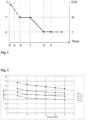
- Figure 1 shows how the regulation of a premixed burner 4 occurs in the ignition step thereof, according to the invention.
- a fan 2 is set in motion at a predetermined rotation speed V p to create an aeriform flow F a that activates the burner 4.
- section A-B the aeriform flow F a is added with a fuel gas flow F g , mainly and/or essentially composed of hydrogen H 2 , so as to obtain an air and fuel gas mixture M ag with an excess air factor ⁇ ⁇ 2.5.
- a sensor for the volumetric concentration of hydrogen in the air and fuel gas mixture M ag may be used to ensure that the excess air factor ⁇ is the desired one.
- burner 4 may only take place once the excess air factor ⁇ has taken the desired value.
- the air and fuel gas mixture M ag escaping from the holes of the burner 4 is ignited by means of an ignition device 5, for example a conventional ignition electrode 5. After the ignition, the air and fuel gas mixture M ag continues maintaining a value of ⁇ ⁇ 2.5 for a stabilisation time ts ⁇ 5 seconds (section B-C) of the flame.
- the inventors have verified that carrying out the ignition of an air and fuel gas mixture M ag with an excess air value ⁇ ⁇ 2.5 and maintaining such excess air value ⁇ for at least 5 seconds allows drastically reducing the risk of flashbacks at the time of ignition of the burner 4.
- the excess air factor ⁇ is progressively reduced, for example in a linear manner, until reaching a ⁇ target value of 1.3 ⁇ ⁇ ⁇ 2.5.
- the excess air factor ⁇ drops to a value ⁇ target of 1.5 ⁇ ⁇ ⁇ 2.0 (section C-D-E of the diagram in Fig. 1 ).
- the air and fuel gas mixture M ag may begin according to the required thermal power.
- the temperature T b of the burner 4 is cyclically monitored, for example at time intervals ⁇ t, to check whether the temperature of the burner 4 remains within predetermined limits, corresponding to a maximum temperature T sup (above which a flashback may occur) and at a minimum temperature T inf (below which there is a risk of flame lift-off).
- this excess air factor ⁇ target remains constant; in an alternative embodiment, the excess air factor ⁇ target varies depending on the thermal power, but always remaining in the range of the excess air values ⁇ target mentioned above, i.e. 1.3 ⁇ ⁇ ⁇ 2.5, preferably 1.5 ⁇ ⁇ ⁇ 2.0.
- the excess air factor ⁇ target is progressively increased by a predetermined value ⁇ , for example intermittently, until the burner temperature T b is brought back 4 below such value T sup .
- the excess air factor ⁇ target is progressively reduced by a predetermined value ⁇ , for example intermittently, until the temperature T b of the burner 4 is brought back above such value T inf .
- the time interval ⁇ t with which the temperature check T b of the burner 4 and the possible correction of the excess air ⁇ is carried out may vary according to the time constant of the system, more precisely according to the thermal inertia of the burner 4.
- such time interval ⁇ t 1 second.
- the inventors have verified that the periodic check of the temperature T b of the burner 4 and any periodic regulation of the excess air ⁇ of the burned mixture M ag allow keeping the flame stable avoiding, in particular, the risks of flashback when the burner is operated for a long time at reduced powers, without excessively penalising the thermal throughtput thereof.
- control and regulation method described above may be performed by means of a device 1, for controlling and regulating the operation of a premixed gas burner 4 suitable for burning a fuel gas substantially and/or essentially consisting of hydrogen H 2 .
- the device 1 comprises a first duct 11, or combustion air inflow duct F a , a second duct 12, or fuel gas inflow duct F g , a variable speed fan 2, having an intake 21, connected to the first duct 11, and a delivery 22.
- the speed of fan 2 may vary according to the required thermal power.
- Venturi tube 3 which may be positioned downstream of the fan ( Fig. 3 ) or upstream of the same ( Fig. 4 ).
- the second duct 12 is in communication with the narrow section of the Venturi tube 3, so that the fuel gas F g is sucked.
- a conventional motorised (or more generally modulating) valve 7 is provided, for regulating the flow rate of the fuel gas F g that passes through the second duct 12 and thus for regulating the excess air ⁇ .
- a third duct 13, or air mixture and fuel gas outflow duct M ag is provided, located downstream of the Venturi tube 3 which feeds a burner 4.
- the burner 4 may be a conventional burner of the perforated surface type, inserted inside a combustion chamber 41.
- An ignition device 5 (for example a known ignition electrode) is provided to ignite the air and fuel gas mixture M ag escaping from the Venturi tube 3 and reaching the burner 4.
- a conventional non-return valve 14 may be provided upstream of the burner 4.
- a first sensor 61 located inside the first duct 11, allows measuring a physical characteristic of the air flow F a .
- the first sensor 61 is an air mass flow sensor that allows detecting the mass flow rate of the air sucked by the fan 2.
- a second sensor 62 located in the Venturi tube 3 or downstream of it, allows measuring the concentration of hydrogen H 2 present in the created air and fuel gas mixture M ag .
- the first and second sensors 61, 62 allow controlling the excess air factor ⁇ of the mixture M ag before it reaches the burner 4.
- a third sensor 63 or temperature sensor, is able to detect the temperature T b of the burner 4.
- Such fourth sensor 64 may be an optical sensor able to detect the presence of hydroxyl radicals OH.
- said fourth sensor 64 may consist of a low thermal inertia thermocouple, suitable for measuring the temperature of the flame.
- the fourth sensor 64 serves only to detect the presence of the flame, but does not provide any detail on the quality of the combustion in place.
- a regulator 8 is provided that receives the signals in input detected by the sensors 61, 62, 63, 64 and a control signal Sc indicative of the desired thermal power.
- the regulator 8 is able to provide an ignition signal to the ignition device 5, a fan speed regulation signal 2 and a motorised valve opening regulation signal 7.
- a fifth sensor 65 is provided, located inside the second duct 12, which allows detecting a physical quantity of the fuel gas flow F g .
- the fifth sensor 65 is a mass flow sensor of the fuel gas F g .
- the value of ⁇ is determined by the measurements of the mass sensor 61 of the air F a and the hydrogen concentration sensor 62, while the temperature sensor 63 is only used to correct the value of ⁇ if the temperature T b of the burner 4 takes abnormal values.
Landscapes
- Engineering & Computer Science (AREA)
- Chemical & Material Sciences (AREA)
- Combustion & Propulsion (AREA)
- Mechanical Engineering (AREA)
- General Engineering & Computer Science (AREA)
- Regulation And Control Of Combustion (AREA)
Claims (11)
- Regelungsverfahren eines Gasvormischbrenners (4), der mit Wasserstoff H2 gespeist wird, das die Schritte umfasst:a) Starten eines Gebläses (2) mit einer vorbestimmten Geschwindigkeit Vp, um einen luftförmigen Strom Fa zu erzeugen,b) Hinzufügen eines Brenngasstroms Fg, der hauptsächlich und/oder im Wesentlichen aus Wasserstoff H2 besteht, zu dem luftförmigen Strom Fa, derart, um ein Luft- und Brenngasgemisch Mag mit einem Luftüberschussfaktor λ ≥ 2,5 zu erhalten,c) Zünden des Luft- und Brenngasgemisches Mag,d) Aufrechterhalten der Verbrennung des Luft- und Brenngasgemisches Mag für eine Stabilisierungszeit ts,e) schrittweises Verringern des Luftüberschussfaktors λ bis zu einem λtarget von 1,3 < λ < 2,5,dadurch gekennzeichnet, dass die Stabilisierungszeit ts ≥ 5 Sekunden ist.
- Verfahren nach Anspruch 1,
umfassend die weiteren Schritte:f) Überprüfen der erforderlichen Wärmeleistung,g) Regeln des Durchsatzes des Luft- und Brenngasgemisches Mag gemäß der erforderlichen Wärmeleistung unter Beibehaltung des Luftüberschussfaktors λtarget. - Verfahren nach Anspruch 2,
umfassend die weiteren Schritte:h) periodisches Überprüfen der Temperatur Tb des Brenners (4) in jedem Zeitintervall Δt:- wenn die Brennertemperatur Tb einen vorbestimmten maximalen Temperaturwert Tsup überschreitet, Erhöhen des Luftüberschussfaktors λtarget um einen vorbestimmten Wert Δλ,- wenn die Brennertemperatur Tb niedriger als ein vorbestimmter minimaler Temperaturwert Tinf ist, Verringern des Luftüberschussfaktors λtarget um einen vorbestimmten Wert Δλ,i) periodisches Zurückkehren zu Punkt h). - Verfahren nach Anspruch 1, wobei
im Punkt e) der Luftüberschussfaktor λ schrittweise auf einen bevorzugten Wert λtarget von 1,5 < λ < 2,0 reduziert wird. - Verfahren nach Anspruch 3, wobei
im Punkt h) das Zeitintervall Δt vorzugsweise gleich 1 Sekunde ist. - Verfahren nach Anspruch 2, wobei
im Punkt g) der Luftüberschussfaktor λtarget konstant bleibt. - Verfahren nach Anspruch 2, wobei
im Punkt g) der Luftüberschussfaktor λtarget in Abhängigkeit von der Wärmeleistung variiert, wobei er immer im Bereich der Luftüberschusswerte λtarget bleibt. - Vorrichtung (1) zum Durchführen des Regelungsverfahrens eines Gasvormischbrenners (4), der hauptsächlich und/oder im Wesentlichen mit Wasserstoff H2 gespeist wird, umfassend:a) einen ersten Kanal (11) oder Verbrennungsluft-Einströmkanal Fa,b) einen zweiten Kanal (12) oder Brenngas-Einströmkanal Fg,c) ein Gebläse (2) mit variabler Drehzahl, das einen Einlass (21), der mit dem ersten Kanal (11) verbunden ist, und einen Auslass (22) aufweist,d) ein motorisiertes Ventil (7), um den Durchsatz des Brenngases Fg, das durch den zweiten Kanal (12) hindurchgeht, zu regeln,e) ein Venturirohr (3) zum Mischen der Luft Fa, die aus dem ersten Kanal (11) kommt, mit dem Brenngas Fg, das aus dem zweiten Kanal (12) kommt,f) einen dritten Kanal (13) oder Ausströmkanal eines Luft- und Brenngasgemisches Mag, der stromabwärts des Venturirohrs (3) angeordnet ist,g) mindestens einen Brenner (4), insbesondere einen Brenner des Typs mit perforierter Oberfläche, der mit dem dritten Kanal (13) verbunden ist, wobei der Brenner (4) in eine Brennkammer (41) eingesetzt ist,h) eine Zündvorrichtung (5), um das Luft- und Brenngasgemisch Mag zu zünden, das aus dem Brenner (4) austritt,i) einen ersten Sensor (61) oder Luftmassendurchsatzsensor Fa, der im Inneren des ersten Kanals (11) angeordnet ist,j) einen zweiten Sensor (62) oder Wasserstoffkonzentrationssensor H2, der in dem Venturirohr (3) oder stromabwärts des Venturirohrs (3) angeordnet ist,k) einen vierten Sensor (64) zum Erkennen des Vorhandenseins einer Flamme im Inneren der Brennkammer (41),l) einen Regler (8), der geeignet ist, im Eingang zu empfangen:wobei der Regler konfiguriert ist, um die Vorrichtung dazu zu veranlassen, gemäß den Schritten des Verfahrens nach einem der Ansprüche 1, 2 und 4-7 zu arbeiten.- ein Signal Sc, das für die erforderliche Wärmeleistung indikativ ist,- ein Signal, das für den Luftmassendurchsatz Fa indikativ ist, das von dem ersten Sensor (61) bereitgestellt wird,- ein Signal, das für die Wasserstoffkonzentration H2 in dem Luft- und Brenngasgemisch Mag indikativ ist, das von dem zweiten Sensor (62) bereitgestellt wird,- ein Signal, das für das Vorhandensein der Flamme indikativ ist, das von dem vierten Sensor (64) bereitgestellt wird,und im Ausgang bereitzustellen:- ein Zündsignal an die Zündvorrichtung (5),- ein Signal für die Regelung der Drehzahl des Gebläses (2) und- ein Signal für die Regelung der Öffnung des motorisierten Ventils (7),
- Vorrichtung (1) nach Anspruch 8,ferner umfassend einen dritten Sensor (63) oder Temperatursensor, der in der Lage ist, die Temperatur Tb des Brenners (4) zu erfassen,und wobei der Regler (8) einen Eingang aufweist, der geeignet ist, ein Signal zu empfangen, das für die Temperatur Tb des Brenners (4) indikativ ist,und im Ausgang bereitzustellen:- ein Signal für die Drehzahlregelung des Gebläses (2),- ein Signal für die Regelung der Öffnung des motorisierten Ventils (7) und- ein Signal für die Regelung der Wärmeleistung,wobei der Regler konfiguriert ist, um die Vorrichtung dazu zu veranlassen, gemäß den Schritten des Verfahrens nach Anspruch 3 zu arbeiten.
- Vorrichtung (1), nach einem der Ansprüche ab Anspruch 8,Ferner umfassend einen fünften Sensor (65) oder Massendurchsatzsensor des Brenngases Fg, der im Inneren des zweiten Kanals (12) angeordnet ist,und wobei der Regler (8) einen Eingang aufweist, der geeignet ist, ein Signal zu empfangen, das für den Massendurchsatz des Brenngases Fg indikativ ist.
- Vorrichtung (1) nach Anspruch 8,
wobei der fünfte Sensor (64) ein optischer Sensor oder ein Thermoelement mit geringer thermischer Trägheit ist.
Applications Claiming Priority (2)
| Application Number | Priority Date | Filing Date | Title |
|---|---|---|---|
| IT202100011423 | 2021-05-05 | ||
| PCT/IB2022/053076 WO2022234359A1 (en) | 2021-05-05 | 2022-04-01 | Regulation method of a premix gas burner and control and regulation device for carrying out the method |
Publications (2)
| Publication Number | Publication Date |
|---|---|
| EP4334643A1 EP4334643A1 (de) | 2024-03-13 |
| EP4334643B1 true EP4334643B1 (de) | 2025-02-26 |
Family
ID=77022013
Family Applications (1)
| Application Number | Title | Priority Date | Filing Date |
|---|---|---|---|
| EP22715396.2A Active EP4334643B1 (de) | 2021-05-05 | 2022-04-01 | Regelverfahren eines vormischgasbrenners sowie steuer- und regeleinrichtung zur durchführung des verfahrens |
Country Status (4)
| Country | Link |
|---|---|
| US (1) | US12372233B2 (de) |
| EP (1) | EP4334643B1 (de) |
| CN (1) | CN117242300A (de) |
| WO (1) | WO2022234359A1 (de) |
Families Citing this family (1)
| Publication number | Priority date | Publication date | Assignee | Title |
|---|---|---|---|---|
| CN117128512B (zh) * | 2023-08-30 | 2024-02-02 | 襄阳中和机电技术有限公司 | 一种氢燃料燃烧器 |
Citations (14)
| Publication number | Priority date | Publication date | Assignee | Title |
|---|---|---|---|---|
| US3671169A (en) | 1971-03-15 | 1972-06-20 | Honeywell Inc | Delayed fuel and post ignition timed burner control system |
| GB1374015A (en) | 1971-09-22 | 1974-11-13 | Cem Comp Electro Mec | Burner apparatus |
| GB1436088A (en) | 1973-09-07 | 1976-05-19 | Landis & Gyr Ag | Control and monitoring devices for oil and gas burners |
| DE19924284A1 (de) | 1998-05-30 | 1999-12-23 | Christoph Nailis | Verfahren zur Messung eines Luft-Brennstoff-Verhältnisses in einem Brennraum |
| DE19941978A1 (de) | 1999-09-03 | 2001-03-15 | Stiebel Eltron Gmbh & Co Kg | Verfahren und Einrichtung zur Erzeugung eines Synthesegases |
| EP1207340A2 (de) | 2000-11-18 | 2002-05-22 | Buderus Heiztechnik GmbH | Verfahren zur Regelung eines Gasbrenners |
| JP2005201648A (ja) | 2004-01-13 | 2005-07-28 | Tokyo Gas Co Ltd | 発熱量算出装置及びその方法、並びに発熱量測定システム |
| EP1571395A1 (de) | 2004-03-02 | 2005-09-07 | Riello S.p.a. | Vorrichtung zur Flammenüberwachung eines Brenners |
| DE102004055716A1 (de) | 2004-06-23 | 2006-01-12 | Ebm-Papst Landshut Gmbh | Verfahren zur Regelung und Steuerung einer Feuerungseinrichtung und Feuerungseinrichtung |
| EP1672280A1 (de) | 2004-12-01 | 2006-06-21 | G. Kromschröder Aktiengesellschaft | Verfahren zum Brennerstart eines Gasheizgeräts |
| WO2011117810A2 (en) | 2010-03-23 | 2011-09-29 | Idea S.P.A. | A method and device for controlling the combustive air flow rate of a burner in general. |
| EP3663648A1 (de) | 2018-12-05 | 2020-06-10 | Vaillant GmbH | Verfahren und vorrichtung zur regelung des mischungsverhältnisses von verbrennungsluft und brenngas bei einem verbrennungsprozess |
| WO2020182902A1 (en) | 2019-03-12 | 2020-09-17 | Bekaert Combustion Technology B.V. | Method to operate a modulating burner |
| WO2021078949A1 (en) * | 2019-10-25 | 2021-04-29 | Bekaert Combustion Technology B.V. | Surface stabilized fully premixed gas premix burner for burning hydrogen gas, and method for starting such burner |
Family Cites Families (13)
| Publication number | Priority date | Publication date | Assignee | Title |
|---|---|---|---|---|
| GB1421551A (en) * | 1972-01-22 | 1976-01-21 | British Gas Corp | Burner for gaseous fuel |
| US4168949A (en) * | 1977-09-26 | 1979-09-25 | Honeywell Inc. | Flame signal stabilization circuit |
| EP0331037B1 (de) * | 1988-02-27 | 1995-01-04 | Osaka Gas Co., Ltd. | Gasbrenner |
| DE10049203A1 (de) * | 2000-10-05 | 2002-05-23 | Alstom Switzerland Ltd | Verfahren zur Brennstoffeinleitung in einen Vormischbrenner |
| US6880548B2 (en) * | 2003-06-12 | 2005-04-19 | Honeywell International Inc. | Warm air furnace with premix burner |
| JP2006134643A (ja) * | 2004-11-04 | 2006-05-25 | Nissan Motor Co Ltd | 燃料電池システム |
| US8408896B2 (en) * | 2007-07-25 | 2013-04-02 | Lummus Technology Inc. | Method, system and apparatus for firing control |
| DE102010044762A1 (de) * | 2010-09-08 | 2012-03-08 | Honeywell Technologies S.A.R.L. | Vorrichtung zur Kalibrierung einer Gasbrennerregelung |
| DE102011117736A1 (de) * | 2011-11-07 | 2013-05-08 | Honeywell Technologies Sarl | Verfahren zum Betreiben eines Gasbrenners |
| ITBO20120568A1 (it) * | 2012-10-17 | 2014-04-18 | Gas Point S R L | Apparecchiatura di regolazione e controllo della combustione in un bruciatore a gas combustibile |
| EP3333482B1 (de) * | 2016-12-06 | 2019-09-25 | Honeywell Technologies Sarl | Gasbrennersteuergerätadapter, gasbrennergerät mit solch einem gasbrennersteuergerätadapter und verfahren zum betrieb solch eines gasbrennergeräts |
| WO2019049046A2 (en) * | 2017-09-05 | 2019-03-14 | John Zink Company, Llc | METHOD AND APPARATUS RELATED TO A LOW EMISSION NOX AND CO 2 COMBUSTION BURNER |
| US11073281B2 (en) * | 2017-12-29 | 2021-07-27 | Honeywell International Inc. | Closed-loop programming and control of a combustion appliance |
-
2022
- 2022-04-01 EP EP22715396.2A patent/EP4334643B1/de active Active
- 2022-04-01 CN CN202280030573.1A patent/CN117242300A/zh active Pending
- 2022-04-01 WO PCT/IB2022/053076 patent/WO2022234359A1/en not_active Ceased
- 2022-04-01 US US18/556,925 patent/US12372233B2/en active Active
Patent Citations (14)
| Publication number | Priority date | Publication date | Assignee | Title |
|---|---|---|---|---|
| US3671169A (en) | 1971-03-15 | 1972-06-20 | Honeywell Inc | Delayed fuel and post ignition timed burner control system |
| GB1374015A (en) | 1971-09-22 | 1974-11-13 | Cem Comp Electro Mec | Burner apparatus |
| GB1436088A (en) | 1973-09-07 | 1976-05-19 | Landis & Gyr Ag | Control and monitoring devices for oil and gas burners |
| DE19924284A1 (de) | 1998-05-30 | 1999-12-23 | Christoph Nailis | Verfahren zur Messung eines Luft-Brennstoff-Verhältnisses in einem Brennraum |
| DE19941978A1 (de) | 1999-09-03 | 2001-03-15 | Stiebel Eltron Gmbh & Co Kg | Verfahren und Einrichtung zur Erzeugung eines Synthesegases |
| EP1207340A2 (de) | 2000-11-18 | 2002-05-22 | Buderus Heiztechnik GmbH | Verfahren zur Regelung eines Gasbrenners |
| JP2005201648A (ja) | 2004-01-13 | 2005-07-28 | Tokyo Gas Co Ltd | 発熱量算出装置及びその方法、並びに発熱量測定システム |
| EP1571395A1 (de) | 2004-03-02 | 2005-09-07 | Riello S.p.a. | Vorrichtung zur Flammenüberwachung eines Brenners |
| DE102004055716A1 (de) | 2004-06-23 | 2006-01-12 | Ebm-Papst Landshut Gmbh | Verfahren zur Regelung und Steuerung einer Feuerungseinrichtung und Feuerungseinrichtung |
| EP1672280A1 (de) | 2004-12-01 | 2006-06-21 | G. Kromschröder Aktiengesellschaft | Verfahren zum Brennerstart eines Gasheizgeräts |
| WO2011117810A2 (en) | 2010-03-23 | 2011-09-29 | Idea S.P.A. | A method and device for controlling the combustive air flow rate of a burner in general. |
| EP3663648A1 (de) | 2018-12-05 | 2020-06-10 | Vaillant GmbH | Verfahren und vorrichtung zur regelung des mischungsverhältnisses von verbrennungsluft und brenngas bei einem verbrennungsprozess |
| WO2020182902A1 (en) | 2019-03-12 | 2020-09-17 | Bekaert Combustion Technology B.V. | Method to operate a modulating burner |
| WO2021078949A1 (en) * | 2019-10-25 | 2021-04-29 | Bekaert Combustion Technology B.V. | Surface stabilized fully premixed gas premix burner for burning hydrogen gas, and method for starting such burner |
Non-Patent Citations (3)
| Title |
|---|
| ANONYMOUS: "DIN EN 15502-1:2012-10 Heizkessel für gasförmige Brennstoffe - Teil 1: Allgemeine Anforderungen und Prüfungen; Deutsche Fassung EN 15502-1:2012", DIN EN NORM, DIN, DE, De, pages 1 - 154, XP009564194, Retrieved from the Internet <URL:https://www.dinmedia.de/de/norm/din-en-15502-1/154349319> |
| ANONYMOUS: "DIN EN 437:2009-09 Prüfgase - Prüfdrücke - Gerätekategorien; Deutsche Fassung EN 437:2003+A1:2009", DIN EN NORM, DIN, DE, DE, pages 1 - 54, XP009564193, Retrieved from the Internet <URL:https://www.dinmedia.de/en/standard/din-en-437/111624338> |
| ANONYMOUS: "Gas Burner Safety Control DKG 972 (0651.10-01-e/03/02)", MANUAL, SATRONIC AG - A HONEYWELL COPMPANY, pages 1 - 6, XP093342041, Retrieved from the Internet <URL:https://honeyvell.energy/wa-data/public/site/DKG/Manual%20Honeywell%20(Satronic)%20DKG972%20(en).pdf> |
Also Published As
| Publication number | Publication date |
|---|---|
| CA3215692A1 (en) | 2022-11-10 |
| US20240200773A1 (en) | 2024-06-20 |
| WO2022234359A1 (en) | 2022-11-10 |
| CN117242300A (zh) | 2023-12-15 |
| US12372233B2 (en) | 2025-07-29 |
| EP4334643A1 (de) | 2024-03-13 |
Similar Documents
| Publication | Publication Date | Title |
|---|---|---|
| EP3948077B1 (de) | Verfahren zum betrieb eines vormischgasbrenners, vormischgasbrenner und kessel | |
| US6640548B2 (en) | Apparatus and method for combusting low quality fuel | |
| US8282389B2 (en) | Modular flare stack and method of flaring waste gas | |
| US4588372A (en) | Flame ionization control of a partially premixed gas burner with regulated secondary air | |
| JP2022524534A (ja) | 調節バーナーの運転方法 | |
| US8020387B2 (en) | Method of operating a burner, including a combustion chamber with a low nitrous oxide emission | |
| US9568195B2 (en) | Combustion efficiency control systems | |
| EP4334643B1 (de) | Regelverfahren eines vormischgasbrenners sowie steuer- und regeleinrichtung zur durchführung des verfahrens | |
| US6658856B2 (en) | Hybrid lean premixing catalytic combustion system for gas turbines | |
| CA3215692C (en) | Regulation method of a premix gas burner and control and regulation device for carrying out the method | |
| RU2360183C1 (ru) | Автоматическая блочная горелка для сжигания топлива в виде газовоздушной смеси, горелочная головка и способ управления работой блочной горелки | |
| CN111780154B (zh) | 用燃气进行燃烧的机器的控制设备和方法及燃气热水器 | |
| CN111981479B (zh) | 预混燃烧器控制方法及装置 | |
| JP3453973B2 (ja) | 予混合燃焼装置の制御方法 | |
| JPH06101808A (ja) | 予混合燃焼装置とその燃焼制御方法 | |
| CN209783322U (zh) | 烟气加热装置 | |
| CA3038928C (en) | High turndown boiler and system and method for controlling a boiler | |
| EP4265965A1 (de) | Steuermechanismus für ein verbrennungsgerät | |
| JP2004519651A (ja) | 触媒燃焼システムにおける熱NOx低減方法 | |
| JP2001153363A (ja) | ガスタービン燃焼器 |
Legal Events
| Date | Code | Title | Description |
|---|---|---|---|
| STAA | Information on the status of an ep patent application or granted ep patent |
Free format text: STATUS: UNKNOWN |
|
| STAA | Information on the status of an ep patent application or granted ep patent |
Free format text: STATUS: THE INTERNATIONAL PUBLICATION HAS BEEN MADE |
|
| PUAI | Public reference made under article 153(3) epc to a published international application that has entered the european phase |
Free format text: ORIGINAL CODE: 0009012 |
|
| STAA | Information on the status of an ep patent application or granted ep patent |
Free format text: STATUS: REQUEST FOR EXAMINATION WAS MADE |
|
| 17P | Request for examination filed |
Effective date: 20231107 |
|
| AK | Designated contracting states |
Kind code of ref document: A1 Designated state(s): AL AT BE BG CH CY CZ DE DK EE ES FI FR GB GR HR HU IE IS IT LI LT LU LV MC MK MT NL NO PL PT RO RS SE SI SK SM TR |
|
| P01 | Opt-out of the competence of the unified patent court (upc) registered |
Effective date: 20240318 |
|
| DAV | Request for validation of the european patent (deleted) | ||
| DAX | Request for extension of the european patent (deleted) | ||
| GRAP | Despatch of communication of intention to grant a patent |
Free format text: ORIGINAL CODE: EPIDOSNIGR1 |
|
| STAA | Information on the status of an ep patent application or granted ep patent |
Free format text: STATUS: GRANT OF PATENT IS INTENDED |
|
| GRAS | Grant fee paid |
Free format text: ORIGINAL CODE: EPIDOSNIGR3 |
|
| GRAA | (expected) grant |
Free format text: ORIGINAL CODE: 0009210 |
|
| STAA | Information on the status of an ep patent application or granted ep patent |
Free format text: STATUS: THE PATENT HAS BEEN GRANTED |
|
| INTG | Intention to grant announced |
Effective date: 20250103 |
|
| AK | Designated contracting states |
Kind code of ref document: B1 Designated state(s): AL AT BE BG CH CY CZ DE DK EE ES FI FR GB GR HR HU IE IS IT LI LT LU LV MC MK MT NL NO PL PT RO RS SE SI SK SM TR |
|
| REG | Reference to a national code |
Ref country code: GB Ref legal event code: FG4D |
|
| REG | Reference to a national code |
Ref country code: CH Ref legal event code: EP |
|
| REG | Reference to a national code |
Ref country code: DE Ref legal event code: R096 Ref document number: 602022011153 Country of ref document: DE |
|
| REG | Reference to a national code |
Ref country code: IE Ref legal event code: FG4D |
|
| PGFP | Annual fee paid to national office [announced via postgrant information from national office to epo] |
Ref country code: NL Payment date: 20250418 Year of fee payment: 4 |
|
| REG | Reference to a national code |
Ref country code: NL Ref legal event code: FP |
|
| PG25 | Lapsed in a contracting state [announced via postgrant information from national office to epo] |
Ref country code: RS Free format text: LAPSE BECAUSE OF FAILURE TO SUBMIT A TRANSLATION OF THE DESCRIPTION OR TO PAY THE FEE WITHIN THE PRESCRIBED TIME-LIMIT Effective date: 20250526 |
|
| PG25 | Lapsed in a contracting state [announced via postgrant information from national office to epo] |
Ref country code: FI Free format text: LAPSE BECAUSE OF FAILURE TO SUBMIT A TRANSLATION OF THE DESCRIPTION OR TO PAY THE FEE WITHIN THE PRESCRIBED TIME-LIMIT Effective date: 20250226 |
|
| PG25 | Lapsed in a contracting state [announced via postgrant information from national office to epo] |
Ref country code: PL Free format text: LAPSE BECAUSE OF FAILURE TO SUBMIT A TRANSLATION OF THE DESCRIPTION OR TO PAY THE FEE WITHIN THE PRESCRIBED TIME-LIMIT Effective date: 20250226 |
|
| PGFP | Annual fee paid to national office [announced via postgrant information from national office to epo] |
Ref country code: DE Payment date: 20250422 Year of fee payment: 4 |
|
| PG25 | Lapsed in a contracting state [announced via postgrant information from national office to epo] |
Ref country code: ES Free format text: LAPSE BECAUSE OF FAILURE TO SUBMIT A TRANSLATION OF THE DESCRIPTION OR TO PAY THE FEE WITHIN THE PRESCRIBED TIME-LIMIT Effective date: 20250226 |
|
| REG | Reference to a national code |
Ref country code: LT Ref legal event code: MG9D |
|
| PG25 | Lapsed in a contracting state [announced via postgrant information from national office to epo] |
Ref country code: NO Free format text: LAPSE BECAUSE OF FAILURE TO SUBMIT A TRANSLATION OF THE DESCRIPTION OR TO PAY THE FEE WITHIN THE PRESCRIBED TIME-LIMIT Effective date: 20250526 Ref country code: IS Free format text: LAPSE BECAUSE OF FAILURE TO SUBMIT A TRANSLATION OF THE DESCRIPTION OR TO PAY THE FEE WITHIN THE PRESCRIBED TIME-LIMIT Effective date: 20250626 |
|
| PGFP | Annual fee paid to national office [announced via postgrant information from national office to epo] |
Ref country code: IT Payment date: 20250430 Year of fee payment: 4 |
|
| PG25 | Lapsed in a contracting state [announced via postgrant information from national office to epo] |
Ref country code: HR Free format text: LAPSE BECAUSE OF FAILURE TO SUBMIT A TRANSLATION OF THE DESCRIPTION OR TO PAY THE FEE WITHIN THE PRESCRIBED TIME-LIMIT Effective date: 20250226 |
|
| PG25 | Lapsed in a contracting state [announced via postgrant information from national office to epo] |
Ref country code: PT Free format text: LAPSE BECAUSE OF FAILURE TO SUBMIT A TRANSLATION OF THE DESCRIPTION OR TO PAY THE FEE WITHIN THE PRESCRIBED TIME-LIMIT Effective date: 20250626 Ref country code: LV Free format text: LAPSE BECAUSE OF FAILURE TO SUBMIT A TRANSLATION OF THE DESCRIPTION OR TO PAY THE FEE WITHIN THE PRESCRIBED TIME-LIMIT Effective date: 20250226 |
|
| PGFP | Annual fee paid to national office [announced via postgrant information from national office to epo] |
Ref country code: FR Payment date: 20250425 Year of fee payment: 4 |
|
| PG25 | Lapsed in a contracting state [announced via postgrant information from national office to epo] |
Ref country code: BG Free format text: LAPSE BECAUSE OF FAILURE TO SUBMIT A TRANSLATION OF THE DESCRIPTION OR TO PAY THE FEE WITHIN THE PRESCRIBED TIME-LIMIT Effective date: 20250226 Ref country code: GR Free format text: LAPSE BECAUSE OF FAILURE TO SUBMIT A TRANSLATION OF THE DESCRIPTION OR TO PAY THE FEE WITHIN THE PRESCRIBED TIME-LIMIT Effective date: 20250527 |
|
| REG | Reference to a national code |
Ref country code: AT Ref legal event code: MK05 Ref document number: 1770959 Country of ref document: AT Kind code of ref document: T Effective date: 20250226 |
|
| PG25 | Lapsed in a contracting state [announced via postgrant information from national office to epo] |
Ref country code: SE Free format text: LAPSE BECAUSE OF FAILURE TO SUBMIT A TRANSLATION OF THE DESCRIPTION OR TO PAY THE FEE WITHIN THE PRESCRIBED TIME-LIMIT Effective date: 20250226 |
|
| PG25 | Lapsed in a contracting state [announced via postgrant information from national office to epo] |
Ref country code: SM Free format text: LAPSE BECAUSE OF FAILURE TO SUBMIT A TRANSLATION OF THE DESCRIPTION OR TO PAY THE FEE WITHIN THE PRESCRIBED TIME-LIMIT Effective date: 20250226 |
|
| PG25 | Lapsed in a contracting state [announced via postgrant information from national office to epo] |
Ref country code: DK Free format text: LAPSE BECAUSE OF FAILURE TO SUBMIT A TRANSLATION OF THE DESCRIPTION OR TO PAY THE FEE WITHIN THE PRESCRIBED TIME-LIMIT Effective date: 20250226 |
|
| PG25 | Lapsed in a contracting state [announced via postgrant information from national office to epo] |
Ref country code: AT Free format text: LAPSE BECAUSE OF FAILURE TO SUBMIT A TRANSLATION OF THE DESCRIPTION OR TO PAY THE FEE WITHIN THE PRESCRIBED TIME-LIMIT Effective date: 20250226 |
|
| PG25 | Lapsed in a contracting state [announced via postgrant information from national office to epo] |
Ref country code: EE Free format text: LAPSE BECAUSE OF FAILURE TO SUBMIT A TRANSLATION OF THE DESCRIPTION OR TO PAY THE FEE WITHIN THE PRESCRIBED TIME-LIMIT Effective date: 20250226 Ref country code: CZ Free format text: LAPSE BECAUSE OF FAILURE TO SUBMIT A TRANSLATION OF THE DESCRIPTION OR TO PAY THE FEE WITHIN THE PRESCRIBED TIME-LIMIT Effective date: 20250226 |
|
| PG25 | Lapsed in a contracting state [announced via postgrant information from national office to epo] |
Ref country code: RO Free format text: LAPSE BECAUSE OF FAILURE TO SUBMIT A TRANSLATION OF THE DESCRIPTION OR TO PAY THE FEE WITHIN THE PRESCRIBED TIME-LIMIT Effective date: 20250226 |
|
| PG25 | Lapsed in a contracting state [announced via postgrant information from national office to epo] |
Ref country code: SK Free format text: LAPSE BECAUSE OF FAILURE TO SUBMIT A TRANSLATION OF THE DESCRIPTION OR TO PAY THE FEE WITHIN THE PRESCRIBED TIME-LIMIT Effective date: 20250226 |
|
| REG | Reference to a national code |
Ref country code: CH Ref legal event code: H13 Free format text: ST27 STATUS EVENT CODE: U-0-0-H10-H13 (AS PROVIDED BY THE NATIONAL OFFICE) Effective date: 20251125 |
|
| REG | Reference to a national code |
Ref country code: DE Ref legal event code: R026 Ref document number: 602022011153 Country of ref document: DE |
|
| PLBI | Opposition filed |
Free format text: ORIGINAL CODE: 0009260 |
|
| PLAX | Notice of opposition and request to file observation + time limit sent |
Free format text: ORIGINAL CODE: EPIDOSNOBS2 |
|
| TPAC | Observations filed by third parties |
Free format text: ORIGINAL CODE: EPIDOSNTIPA |
|
| PG25 | Lapsed in a contracting state [announced via postgrant information from national office to epo] |
Ref country code: LU Free format text: LAPSE BECAUSE OF NON-PAYMENT OF DUE FEES Effective date: 20250401 |
|
| PG25 | Lapsed in a contracting state [announced via postgrant information from national office to epo] |
Ref country code: MC Free format text: LAPSE BECAUSE OF FAILURE TO SUBMIT A TRANSLATION OF THE DESCRIPTION OR TO PAY THE FEE WITHIN THE PRESCRIBED TIME-LIMIT Effective date: 20250226 |
|
| REG | Reference to a national code |
Ref country code: BE Ref legal event code: MM Effective date: 20250430 |
|
| 26 | Opposition filed |
Opponent name: STOLMAR MATTHIAS Effective date: 20251126 |
|
| PG25 | Lapsed in a contracting state [announced via postgrant information from national office to epo] |
Ref country code: BE Free format text: LAPSE BECAUSE OF NON-PAYMENT OF DUE FEES Effective date: 20250430 |
|
| PG25 | Lapsed in a contracting state [announced via postgrant information from national office to epo] |
Ref country code: CH Free format text: LAPSE BECAUSE OF NON-PAYMENT OF DUE FEES Effective date: 20250430 |
|
| PLAF | Information modified related to communication of a notice of opposition and request to file observations + time limit |
Free format text: ORIGINAL CODE: EPIDOSCOBS2 |
|
| PG25 | Lapsed in a contracting state [announced via postgrant information from national office to epo] |
Ref country code: IE Free format text: LAPSE BECAUSE OF NON-PAYMENT OF DUE FEES Effective date: 20250401 |