EP4335292A1 - Auslegervorrichtung und verfahren zum betrieb einer auslegervorrichtung einer landwirtschaftlichen spritze und landwirtschaftliche spritze - Google Patents
Auslegervorrichtung und verfahren zum betrieb einer auslegervorrichtung einer landwirtschaftlichen spritze und landwirtschaftliche spritze Download PDFInfo
- Publication number
- EP4335292A1 EP4335292A1 EP22195115.5A EP22195115A EP4335292A1 EP 4335292 A1 EP4335292 A1 EP 4335292A1 EP 22195115 A EP22195115 A EP 22195115A EP 4335292 A1 EP4335292 A1 EP 4335292A1
- Authority
- EP
- European Patent Office
- Prior art keywords
- boom
- boom section
- section
- chamber
- transport position
- Prior art date
- Legal status (The legal status is an assumption and is not a legal conclusion. Google has not performed a legal analysis and makes no representation as to the accuracy of the status listed.)
- Granted
Links
Images



Classifications
-
- A—HUMAN NECESSITIES
- A01—AGRICULTURE; FORESTRY; ANIMAL HUSBANDRY; HUNTING; TRAPPING; FISHING
- A01M—CATCHING, TRAPPING OR SCARING OF ANIMALS; APPARATUS FOR THE DESTRUCTION OF NOXIOUS ANIMALS OR NOXIOUS PLANTS
- A01M7/00—Special adaptations or arrangements of liquid-spraying apparatus for purposes covered by this subclass
- A01M7/005—Special arrangements or adaptations of the spraying or distributing parts, e.g. adaptations or mounting of the spray booms, mounting of the nozzles, protection shields
- A01M7/0071—Construction of the spray booms
- A01M7/0075—Construction of the spray booms including folding means
-
- A—HUMAN NECESSITIES
- A01—AGRICULTURE; FORESTRY; ANIMAL HUSBANDRY; HUNTING; TRAPPING; FISHING
- A01M—CATCHING, TRAPPING OR SCARING OF ANIMALS; APPARATUS FOR THE DESTRUCTION OF NOXIOUS ANIMALS OR NOXIOUS PLANTS
- A01M7/00—Special adaptations or arrangements of liquid-spraying apparatus for purposes covered by this subclass
- A01M7/0003—Atomisers or mist blowers
- A01M7/0014—Field atomisers, e.g. orchard atomisers, self-propelled, drawn or tractor-mounted
Definitions
- the present disclosure refers to a boom apparatus and a method for operating a boom apparatus for an agricultural sprayer, and an agricultural sprayer.
- Such technology is applied for agricultural sprayers used for dispensing a product such as a spraying material by means of a plurality of sprayer elements received on a boom of the agricultural sprayer, the boom being extendable and retractable.
- Sections of the boom may be folded and unfolded to provide at least an extended working position and a folded transport position.
- the boom of the agricultural sprayer can be brought into an extended orientation for the operation of the agricultural sprayer on the field, wherein the extended orientation is essentially orientated transversely to a driving direction while the agricultural sprayer is moving on the field.
- the folded orientation of the boom sections which may be essentially along the driving direction may be chosen if the agricultural sprayer is moving on a street or road. Also, by folding and unfolding boom sections a working width of the agricultural sprayer may be adjusted.
- Document US 6,293,475 B1 discloses a folding boom for an agricultural sprayer.
- the boom includes a first piece pivotally connected to a second piece.
- the folding boom comprises a hydraulic cylinder for hydraulically pivoting the first boom piece relative to the second boom piece between a folded orientation and an extended orientation.
- the hydraulic cylinder includes a cylinder portion in which a piston structure is received.
- the cylinder portion and the piston structure are configured to slide axially relative to one another when the first boom piece is pivoted relative to the second boom piece.
- the folding boom further includes an accumulator in fluid communication with the cylinder portion for accumulating hydraulic fluid when the first boom piece collides with an obstruction and is pivoted from the extended orientation toward the folded orientation.
- a hydraulic control system is controlling the operation of the hydraulic cylinder in different modes of operation.
- the hydraulic control system is in an operation mode in which a pressure source configured to provide hydraulic pressure to the hydraulic cylinder is prevented from extending or retracting the hydraulic cylinder, thereby, preventing folding or unfolding of the boom.
- the operation mode is to be applied when the agricultural sprayer is dispensing the product in the field.
- a bypass flow line connecting ports of the cylinder portion on both sides of the piston head is open, thereby, allowing flow of a hydraulic fluid through the bypass flow line between the two ports. Therefore, in the operation mode the hydraulic control system is always in a break-away condition allowing flow of the hydraulic fluid through the open bypass flow line.
- the accumulator is connected to the bypass flow line.
- Document US 2003 / 0154704 A1 refers to brush cutting technology including a breakaway system.
- a single horizontal pin attaches the cutter head of a brush cutting machine to the boom and a swing tower, so that a single vertical pin can attach the tractor to the boom, the vertical pin and swing tower allowing the cutter head to have a forward and aft movement for flexibility around immovable objects.
- a breakaway cylinder holds the cutter head at a ninety degree angle relative to the tractor of a brush cutting machine.
- a control in the form of a joystick, remotely raises and lowers the cutter head portion using a single control within the cab.
- a first relief valve bypasses when higher than normal hydraulic pressure is created in the breakaway cylinder and a second relief valve removes excess oil from the breakaway cylinder.
- a switch in the form of a toggle switch, remotely operates the breakaway cylinder and moves the cutter head from within the cab.
- a method for brush cutting with a brush cutting machine having a breakaway system is also disclosed.
- Document US 6,119,963 discloses a boom assembly comprising a central support, a first wing pivotably coupled to the central support so as to rotate about a first axis, a first cylinder-piston assembly having a first end pivotably coupled to the support, a second end pivotably coupled to the first wing at a first pivot point for rotation about a second axis on a first side of the first axis, and a second cylinder-piston assembly having a first end pivotably coupled to the support and a second end pivotably coupled to the first wing at a second pivot point for rotation about a third axis on a second side of the first axis.
- Document WO 2004 / 089077 A1 discloses an agricultural crop spraying apparatus comprising a spray boom consisting of a plurality of mutually hinged boom sections, latch means controlling folding of the boom sections, and sensing means disposed along the front edge of the boom to sense contact with an obstacle, the sensing means being coupled to the latch means to allow folding of the boom sections when an obstruction is sensed.
- Document FR 2 891 110 A1 refers to an assembly for connecting boom sections.
- Document EP 3 363 287 A1 refers to a boom apparatus for an agricultural sprayer, comprising a first boom section of a boom provided with a plurality of sprayer elements for dispensing a product; a second boom section of the boom, the second boom section foldably connected to the first boom section in such a way that the second boom section is pivotable between an extended position in which the second boom section is outwardly extending from the first boom section for forming an extended boom and a folded position in which the second boom section is folded from the extended position in a folding direction for forming a folded boom.
- a pressure relief apparatus comprising a pressure relief flow line connecting the first and second cylinder sub-chambers; and a pressure relief valve provided in the pressure relief flow line in such a way that, in the operation mode, the pressure relief flow line is in a normally blocked condition in which the pressure relief flow line is blocked by the pressure relief valve.
- the pressure relief flow line is in an open condition by the pressure relief valve opening if, because of the second boom section colliding with an obstruction and pivoting rearwardly from the extended position toward the folded position, a pressure in one of the first and second cylinder sub-chambers is exceeding a threshold pressure, thereby, allowing a hydraulic fluid flowing through the pressure relief fluid line directly from the one to the other of the first and second cylinder sub-chambers; and the pressure relief flow line is returning to the normally blocked condition by the pressure relief valve closing if the pressure is falling below the threshold pressure.
- a boom apparatus for an agricultural sprayer comprising: a boom provided with a plurality of sprayer elements for dispensing a spraying material; a central boom section of the boom; a first boom section of the boom, wherein the first boom section is foldably connected to the central boom section in such a way that the first boom section is pivotable between an extended working position in which the first boom section is outwardly extending from the central boom section and a folded transport position in which the first boom section is folded for transportation; a first actuation device for pivoting the first boom section between the folded transport position and the extended working position; a second boom section of the boom, the second boom section being foldably connected to the first boom section in such a way that the second boom section is pivotable between an extended working position in which the second boom section is outwardly extending from the first boom section and a transport position in which the second boom section is folded for transportation; a second actuation device for pivoting the second boom section between the folded transport position and the extended working position.
- the second actuation device comprises a hydraulic actuation device having a hydraulic cylinder comprising: a cylinder portion connected to one of the first and second boom sections; and a piston structure connected to the other of the first and second boom sections, the piston structure having a piston head connected to a piston rod, and the cylinder portion defining a first cylinder sub-chamber located on a first side of the piston head and a second cylinder sub-chamber located on a second side of the piston head, wherein the piston rod is extending in the first cylinder sub-chamber.
- the hydraulic cylinder is provided with the following: a driving source for operating the hydraulic cylinder for pivoting the second boom section between the folded transport position and the extended working position by supplying hydraulic fluid to the hydraulic cylinder through a supply line and discharging hydraulic fluid from the hydraulic cylinder through a discharging line, thereby, causing the hydraulic cylinder to extend or retract; and a pressure relief safety valve provided in a hydraulic safety line connecting the second cylinder sub-chamber to the discharging line.
- the boom apparatus is configured to: pivot the first boom section from the folded transport position to the extended working position while the second boom section is still in the folded transport position with respect to the first boom section; when pivoting the first boom section towards the extended working position, push the second boom section and / or a boom component assigned to the second section against the central boom section and / or a boom component assigned to the central section, thereby, increasing a chamber pressure for hydraulic fluid in the second cylinder sub-chamber; open the pressure relief safety valve for allowing hydraulic fluid flowing from the second cylinder sub-chamber back to the discharging line, if the chamber pressure for the hydraulic fluid in the second cylinder sub-chamber reaches a threshold pressure value, thereby, reducing the chamber pressure for hydraulic fluid in the second cylinder sub-chamber; and in response to reducing the chamber pressure for hydraulic fluid in the second cylinder sub-chamber, move the second boom section out of the folded transport position into a first extended position different from the extended working position and located in the vicinity of the folded transport position.
- a method for operating such boom apparatus comprising: pivoting the first boom section from the folded transport position to the extended working position while the second boom section is still in the folded transport position with respect to the first boom section; when the first boom section is pivoted towards the extended working position, pushing the second boom section and / or a boom component assigned to the second section against the central boom section and / or a boom component assigned to the central section, thereby, increasing a chamber pressure for hydraulic fluid in the second cylinder sub-chamber; opening the pressure relief safety valve for allowing hydraulic fluid flowing from the second cylinder sub-chamber back to the discharging line, if the chamber pressure for the hydraulic fluid in the second cylinder sub-chamber reaches a threshold pressure value, thereby, reducing the chamber pressure for hydraulic fluid in the second cylinder sub-chamber; and in response to reducing the chamber pressure for hydraulic fluid in the second cylinder sub-chamber, moving the second boom section out of the folded transport position into a first extended position located in the vicinity of the folded transport position.
- an agricultural sprayer comprising the boom apparatus is provided.
- the technology proposed allows for safer and more efficient operation of the boom apparatus, especially in the process of unfolding boom sections from the folded transport position for extending the boom. If, for example, the boom is to be operated by only using a limited working width of the boom, i.e. not full working width available, the first boom section pivotably connected to the central or middle boom section can be safely moved from the folded transport position to the unfolded working position with the second boom section still kept in the folded transport position relative to the first boom section. Thereby, the boom can be extended or unfolded to a working width smaller than total working width available for the boom which is present if not only the first boom section, but also the second boom section is unfolded to the unfolded working position.
- the second boom section being in the folded transport position causes damage to any boom component assigned to or located in the central section of the boom. If the second boom section is pushed against some boom component in the central section, the safety mechanism causes the second boom section to open or unfold to some extent, thereby, avoiding damage to the boom component assigned to the central section.
- the boom component for example, can be a frame member of the central boom section. Alternatively or in addition, it can be some functional component assigned to the central section such as a box or a cabinet receiving, for example, a control device applied for operating the boom such as operating boom sections for folding or unfolding.
- the "somewhat" unfolded position of the second boom section in relation to the first boom section being in the unfolded transport position is different from both the folded transport position and the unfolded working position of the second boom section and may also be referred to as unfolded non-working position.
- the discharging line connected to the second sub-chamber through the pressure relieve safety valve may be a hydraulic line of low pressure connected to a tank or reservoir for the hydraulic fluid.
- the low pressure allows for discharging hydraulic fluid from the second cylinder sub-chamber in case of the chamber pressure reaching the threshold pressure value.
- the first and second boom section may be of equal or different boom section length.
- At least one of the boom component assigned to the central section and the boom component assigned to the second section may comprise a protection device configured to protect, at least from collision with the second boom section, the central boom section.
- the protection device for example, may be located on the central or middle boom section and / or in the vicinity of the central boom section. It may be provided, for example, with a protection member orientated, for example, essentially horizontally or vertically.
- the protection device may comprise a roller device, the roller device rolling on the second boom section while the second boom section is pushed against the protection device.
- the roller device supports avoiding unwanted friction between the protection device and the second boom section being pushed against the protection device. Thus, the risk for damage to a member of the second boom section is minimized.
- the protection device may be located on a frame member of a boom frame of the boom.
- the protection device in this and other embodiments, may be extending in at least one of vertical direction and horizontal direction.
- the protection device may be configured to protect a functional component assigned to operation of the boom such as a control device for controlling operation of one or more hydraulic actuation devices applied for pivoting one or more boom sections and / or lifting and lowering the boom with respect to ground level.
- a functional component assigned to operation of the boom such as a control device for controlling operation of one or more hydraulic actuation devices applied for pivoting one or more boom sections and / or lifting and lowering the boom with respect to ground level.
- the functional component may comprise at least one of the following: an actuation control device configured to control operation of at least one of the first actuation device, and the second actuation; a dispensing control device configured to control operation of dispensing the spraying material through the plurality of dispensing devices; and a cabinet configured to receive one or more device assigned to operation of the boom such as at least one of the first actuation device, the actuation control device, and the dispensing control device.
- the protection device may be configured to protect one or all of such devices from damage because of being hit by the second boom section while the first boom section is moved into the unfolded working position.
- the boom apparatus may be further configured to dispense the spraying material through first sprayer elements on the first boom section from the plurality of sprayer elements, while the first boom section is in the extended working position and the second boom section is in the first extended position.
- the boom is provided with limited working width by having the first boom section in the extended working position, but not the second boom section which is still in the vicinity or close to its folded transport position with respect or relatively to the first boom section.
- Second sprayer elements provided on the second boom section may be prevented from dispensing the spraying material.
- the second boom section may be pivoted to the unfolded working position, thereby, extending the working width of the agricultural sprayer on one or both opposite sides of the agricultural sprayer.
- the first actuation device may comprise a further hydraulic actuation device.
- the boom apparatus may further comprise a boom support, wherein the boom apparatus is further configured for a lifting process for lifting the boom from the boom support while both the first and the second boom section are in the folded transport position.
- the boom may be in a secured position when resting on the boom support for transportation. By means of the lifting process the boom is moved out of such secured position to allow unfolding of the boom sections.
- the first boom section and the second boom section which may be extending essentially along a driving direction in the folded transport position, wherein the driving direction is transversely orientated to an extension of the first boom section and the second boom section when being in the extended working position.
- the first boom section and the second boom section are extending essentially transversely to the driving direction when being placed in the extended working position.
- the first boom section and the second boom section may be in an essential parallel orientation when both the first boom section and the second boom section are in the folded transport position.
- the boom apparatus may be further configured to move the second boom section from the extended working position to the first extended position while the first boom section is in the extended working position.
- the working width provided for the boom apparatus can flexibly be adjusted by separately unfolding the first and second boom section, respectively to the unfolded working position.
- the boom apparatus may comprise the following: a detection device configured to detect folding signals at least indicative of the first boom section being in the folded transport position; and a control device functionally connected to the detection device and the second actuation device, and configured to provide, in response to the folding signals, control signals to the second actuation device for pivoting the second boom section to the folded transport position.
- the detection device may comprise a sensor device such as an angle sensor assigned to the first boom section and configured to detect one or more positions for the first boom section.
- the control device may be implemented with, for example, one or more processors configured to generate the control signals in response to processing the folding signals received from the detection device.
- the detection device may comprise at least one of a proximity sensor and a position sensor.
- the proximity sensor can be mounted in a position configured to detect a boom section, for example, on the first boom section, detecting the machine. Or it could be implemented near or in the actuation device folding the first boom section.
- the position sensor for example, may be implemented near or in the actuation device folding the first boom section.
- the sensor may be providing information about the length and / or the position of a moving element of the actuation device.
- the embodiments disclosed above for the boom apparatus can be applied to at least one of the agricultural sprayer and the method for operating the boom apparatus mutatis mutandis.
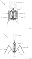
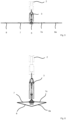
- Fig. 1 to Fig. 8 show schematic representations of an agricultural machine 1 comprising a tractor 2 and an agricultural sprayer 3 hooked to the tractor (trailed agricultural sprayer 3 connected to the tractor 2).
- the agricultural sprayer 3 may be provided as a self-driving machine without need for the tractor 2.
- functional components of the agricultural sprayer 3 could be carried by the tractor 2 in an embodiment.
- the agricultural sprayer 3 comprises a boom apparatus 4 having a boom 5 on which spraying elements are provided for dispensing a product such as a spraying material for agricultural purpose.
- the boom 5 is having a central or middle boom section 6, a first boom section 7 foldably connected to the central boom section 5 and a second boom section 8.
- an additional first boom section 7a and an additional second boom section 8a are provided on an opposite side of the central boom section 6 similar to the first and second boom sections 7, 8.
- the boom 5 may be unfolded completely as it is shown in Fig. 5 , the first and second boom section 7, 8 as well as the additional first and second boom section 7a, 8a being in an unfolded working position and extending outwardly in a direction transversely to a driving direction of the agricultural machine 1.
- a smaller working width is provided according to Fig. 4 and 6 with only the first boom section 7 and the additional first boom section 7a in the unfolded working position, but the second boom section 8 and the additional second boom section 8a being still in a folded position with respect to the first / first additional boom section 7, 7a, such folded position, in relation to the first / first additional boom section 7, 7a, being different from the folded transport position (see Fig. 1 and 8 ).
- Fig. 1 and 8 which show an arrangement of boom sections before unfolding and after folding (back), respectively, the first boom section 7 and the second boom section 8 on one side of the agricultural sprayer 3 and the second boom section 8 and the additional second boom section 8a on the opposite side of the agricultural sprayer 3 are in an essentially parallel orientation to each other in the folded transport position.
- the first boom section 7 and the additional first boom section 7a in the unfolded working position, but not the second boom section 8 and the additional second boom 8a (see Fig. 4 and 6 )
- such parallel orientation is no longer the case, since the second boom section 8 and the additional second boom section 8a are moved out of the folded transport position relative to the first / first additional boom section 7, 7a.
- Relative positioning between the first boom section 7 and the first additional boom section 7a and the second boom section 8 and the second additional boom section 8a as shown in Fig. 4 is the result of unfolding to some extent the first / first additional boom section 7, 7a relative to the second / second additional boom section 8, 8a in the process of unfolding the first / first additional boom section 7, 7a from the folded transport position to the unfolded working position (see Fig. 3 and 4 ).
- the arrangement of the boom sections shown in Fig. 4 may also be referred to as a working position with limited working width.
- An at least similar arrangement may be provided for the boom sections with limited working width (see Fig. 6 ) when the boom sections are partially folded from unfolded working position in Fig. 5 .
- Fig. 7 is showing an arrangement of boom sections after folding the second / second additional boom section 8, 8a from an extended working position to a partially folded working position and then folding the first / first additional boom section 7, 7a to the folded transport position. After this, a folding operation may be conducted automatically that makes the second / second additional boom section 8, 8a fold to the (fully) folded transport position as shown in Fig. 1 .
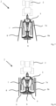
- FIG. 9 shows a schematic representation of details of the central boom section 6.
- a protection device 20 is provided.
- the protection device 20 comprises a protection element 21 provided with protection frame elements 22.
- On vertically extending protection frame elements 22a, 22b roller elements 23a, 23b are provided.
- the vertically extending protection frame elements 22a, 22b are connected by a horizontally extending protection frame element 22c.
- the protection device 20 is preventing the second / second additional boom section 8, 8a from entering a protected space 24 receiving one or more boom components located on or provided with the central boom section 6.
- first / first additional boom section 7, 7a is moved from the folded transport position into the unfolded working position, the second / second additional boom section 8, 8a is pushed against the protection device 20, thereby, unfolding the second / second additional boom section 8, 8a to some minor extent to still a non-working position.
- Fig. 10 shows a schematic representation of functional operation components for operating the boom apparatus 4 provided with the plurality of boom sections.
- the reference numerals as disclosed in Fig. 1 to 9 are assigned.
- the first boom section 7 and the first additional boom section 7a are assigned a first actuation device 30 and a first additional actuation device 30a, respectively, for pivoting the respective boom section between the folded transport position and the unfolded working position.
- the second boom section 8 and the second additional boom section 8a is assigned a second actuation device 31 and an additional second actuation device 31a, respectively, configured to move the respective boom section between the folded transport position and the unfolded working position.
- the different actuation devices are each provided with an hydraulic actuation device comprising a hydraulic cylinder and a hydraulic drive source for retracting and extracting as it is known as such.
- FIG. 10 there are further boom sections 32, 32a which may be referred to as outer boom sections.
- the further boom section 32, 32a operable to further extend the working width of the boom 4 are assigned further actuation devices 33, 33a for pivoting the further boom sections 32, 32a between the folded transport position and the unfolded working position.
- the second actuation device 31 is provided with a hydraulic actuation device 34 comprising a hydraulic cylinder 34a having a piston 34b dividing the hydraulic cylinder into a first sub-chamber 34c in which a piston rod 34d is extending and a second sub-chamber 34e also referred to as bottom of the hydraulic cylinder 34a.
- the other actuation devices may be implemented with similar hydraulic design as shown in Fig. 10 .
- a pressure relief safety valve 35 is provided in a safety line 36 connecting the second cylinder sub-chamber 34e with a discharging line 37.
- the movement of the second boom section 8 is driven by a hydraulic mechanism provided with the second actuation device 31 having the hydraulic actuation device 34.
- a driving or pressure source 38 such as a hydraulic pump provides hydraulic pressure for operating the hydraulic cylinder 34a.
- the driving source 38 and, optionally, further functional components are controlled by a hydraulic control system (not shown).
- Such additional functional components may be one or more hydraulic valves.
- the hydraulic cylinder 34a is connected to the hydraulic control system by a first and a second control flow line each allowing the flow of a hydraulic fluid at least into the hydraulic cylinder 34a, such first and second control flow lines providing for a charging line 39 and the discharging line 37 connected to the first and second sub-chamber 34c, 34e, respectively.
- hydraulic fluid is provided through the first and / or the second control flow line to the first and / or second cylinder sub-chamber 34c, 34e in the hydraulic cylinder 34a.
- the technology proposed allows for safer and more efficient operation of the boom apparatus 4 in the process of unfolding boom sections from the folded transport position for extending the boom. If, the boom 5 is to be operated by only using a limited working width of the boom 5, i.e. not full working width used, the first boom section 7 pivotably connected to the central or middle boom section 6 can be safely moved from the folded transport position to the unfolded working position with the second boom section 8 still kept in the folded transport position relative to the first boom section 7. Thereby, the boom 5 can be extended or unfolded to a working width smaller than total working width available for the boom 5 which is present if not only the first boom section 7, but also the second boom 8 section is unfolded to the unfolded working position.
- the safety mechanism comprising the pressure relief safety valve 35 provided in the safety line 36 it is avoided that the second boom section 8 being in the folded transport position causes damage to any boom component assigned to or located in the central boom section 6. If the second boom section 8 is pushed against some boom component in the central boom section 6, the safety mechanism causes the second boom section 8 to open or unfold to some extent, thereby, avoiding damage to the boom component assigned to the central section 6. Such pushing of the second boom section 8 against the central boom section 6 causes an increase of chamber pressure in the second sub-chamber 34e. In response the pressure relief safety valve 35 will open the safety line 36, thereby, allowing hydraulic fluid to flow back into the (low pressure) discharging line 37.
Landscapes
- Life Sciences & Earth Sciences (AREA)
- Engineering & Computer Science (AREA)
- Insects & Arthropods (AREA)
- Pest Control & Pesticides (AREA)
- Wood Science & Technology (AREA)
- Zoology (AREA)
- Environmental Sciences (AREA)
- Catching Or Destruction (AREA)
Priority Applications (2)
| Application Number | Priority Date | Filing Date | Title |
|---|---|---|---|
| PL22195115.5T PL4335292T3 (pl) | 2022-09-12 | 2022-09-12 | Urządzenie wysięgnikowe oraz sposób obsługi urządzenia wysięgnikowego opryskiwacza rolniczego, a także opryskiwacz rolniczy |
| EP22195115.5A EP4335292B1 (de) | 2022-09-12 | 2022-09-12 | Auslegervorrichtung und verfahren zum betrieb einer auslegervorrichtung einer landwirtschaftlichen spritze und landwirtschaftliche spritze |
Applications Claiming Priority (1)
| Application Number | Priority Date | Filing Date | Title |
|---|---|---|---|
| EP22195115.5A EP4335292B1 (de) | 2022-09-12 | 2022-09-12 | Auslegervorrichtung und verfahren zum betrieb einer auslegervorrichtung einer landwirtschaftlichen spritze und landwirtschaftliche spritze |
Publications (3)
| Publication Number | Publication Date |
|---|---|
| EP4335292A1 true EP4335292A1 (de) | 2024-03-13 |
| EP4335292C0 EP4335292C0 (de) | 2025-05-07 |
| EP4335292B1 EP4335292B1 (de) | 2025-05-07 |
Family
ID=83283442
Family Applications (1)
| Application Number | Title | Priority Date | Filing Date |
|---|---|---|---|
| EP22195115.5A Active EP4335292B1 (de) | 2022-09-12 | 2022-09-12 | Auslegervorrichtung und verfahren zum betrieb einer auslegervorrichtung einer landwirtschaftlichen spritze und landwirtschaftliche spritze |
Country Status (2)
| Country | Link |
|---|---|
| EP (1) | EP4335292B1 (de) |
| PL (1) | PL4335292T3 (de) |
Citations (8)
| Publication number | Priority date | Publication date | Assignee | Title |
|---|---|---|---|---|
| US5887390A (en) * | 1996-11-26 | 1999-03-30 | Ag-Chem Equipment, Co., Inc. | Boom swing control device and assembly |
| US6119963A (en) | 1999-07-30 | 2000-09-19 | Case Corporation | Full boom pivot breakaway |
| US6293475B1 (en) | 2000-01-31 | 2001-09-25 | Summers Manufacturing Co., Inc. | Foldable boom for an agricultural sprayer |
| US20030154704A1 (en) | 2002-02-13 | 2003-08-21 | Dallman Jimmie J. | Brush cutting breakaway system |
| WO2004089077A1 (en) | 2003-04-12 | 2004-10-21 | Brian George Knight | Crop spraying apparatus |
| FR2891110A1 (fr) | 2005-09-28 | 2007-03-30 | Pommier S C E B P Sa | Rampe de pulverisation amortie |
| EP3363287A1 (de) | 2017-02-17 | 2018-08-22 | Kverneland Group Nieuw-Vennep BV | Auslegervorrichtung für landwirtschaftliche spritzgeräte, landwirtschaftliches spritzgerät und verfahren zum betreiben einer entsprechenden auslegervorrichtung |
| US20220264859A1 (en) * | 2019-08-29 | 2022-08-25 | Amazon-Werke H. Dreyer SE & Co. KG | Agricultural machine having improved suspension |
-
2022
- 2022-09-12 EP EP22195115.5A patent/EP4335292B1/de active Active
- 2022-09-12 PL PL22195115.5T patent/PL4335292T3/pl unknown
Patent Citations (8)
| Publication number | Priority date | Publication date | Assignee | Title |
|---|---|---|---|---|
| US5887390A (en) * | 1996-11-26 | 1999-03-30 | Ag-Chem Equipment, Co., Inc. | Boom swing control device and assembly |
| US6119963A (en) | 1999-07-30 | 2000-09-19 | Case Corporation | Full boom pivot breakaway |
| US6293475B1 (en) | 2000-01-31 | 2001-09-25 | Summers Manufacturing Co., Inc. | Foldable boom for an agricultural sprayer |
| US20030154704A1 (en) | 2002-02-13 | 2003-08-21 | Dallman Jimmie J. | Brush cutting breakaway system |
| WO2004089077A1 (en) | 2003-04-12 | 2004-10-21 | Brian George Knight | Crop spraying apparatus |
| FR2891110A1 (fr) | 2005-09-28 | 2007-03-30 | Pommier S C E B P Sa | Rampe de pulverisation amortie |
| EP3363287A1 (de) | 2017-02-17 | 2018-08-22 | Kverneland Group Nieuw-Vennep BV | Auslegervorrichtung für landwirtschaftliche spritzgeräte, landwirtschaftliches spritzgerät und verfahren zum betreiben einer entsprechenden auslegervorrichtung |
| US20220264859A1 (en) * | 2019-08-29 | 2022-08-25 | Amazon-Werke H. Dreyer SE & Co. KG | Agricultural machine having improved suspension |
Also Published As
| Publication number | Publication date |
|---|---|
| PL4335292T3 (pl) | 2025-09-08 |
| EP4335292C0 (de) | 2025-05-07 |
| EP4335292B1 (de) | 2025-05-07 |
Similar Documents
| Publication | Publication Date | Title |
|---|---|---|
| US6293475B1 (en) | Foldable boom for an agricultural sprayer | |
| US7073735B2 (en) | Boom breakaway system | |
| US5630547A (en) | Sprayer boom self-leveling lockout and method of sprayer boom operation | |
| US3425628A (en) | Folding boom agricultural sprayer | |
| CA1160886A (en) | Folding sequence control for wing fold implements | |
| EP2042028B1 (de) | Sequenz- und Zeitgabesteuerung für Vorrichtung zum Ausstoßen großer runder Ballen | |
| EP2311309B1 (de) | Aufhängungssystem für einen Abladeförderer | |
| CA3080101C (en) | Wing plow apparatus for vehicle | |
| US20130233580A1 (en) | Smooth forward folding implement frame | |
| US10780831B2 (en) | Mounted retractable catwalk for trucks, utility, construction, and industrial vehicles and equipment | |
| US7152811B2 (en) | Hydraulic boom stabilization device | |
| EP4335292B1 (de) | Auslegervorrichtung und verfahren zum betrieb einer auslegervorrichtung einer landwirtschaftlichen spritze und landwirtschaftliche spritze | |
| EP3474655B1 (de) | Landwirtschaftliche maschine und verfahren zur verarbeitung von feldfrüchten | |
| US5596823A (en) | Hydraulic system for a double acting cylinder | |
| EP1615496B1 (de) | Landwirtschaftliche feldspritze | |
| US6349529B1 (en) | Operating device for an agricultural machine | |
| EP3363287B1 (de) | Auslegervorrichtung für ein landwirtschaftliches spritzgerät, landwirtschaftliches spritzgerät und verfahren zum betreiben einer entsprechenden auslegervorrichtung | |
| JP7820221B2 (ja) | ブーム散布装置及びブーム開閉用の流体圧シリンダ | |
| NL8301415A (nl) | Maai-inrichting voor een berm. | |
| KR20220005762A (ko) | 절첩식 자동 스위칭 방제장치 | |
| CN114403109A (zh) | 一种喷杆折叠与避障机构及具有该机构的喷杆喷雾机 | |
| US7340877B2 (en) | Cutter unit support roller | |
| EP3753404A1 (de) | Anordnung für einen aus- und einziehbaren ausleger einer landwirtschaftlichen maschine und landwirtschaftliche spritze | |
| EP3892095B1 (de) | Auslegeranordnung für eine landwirtschaftliche spritze, landwirtschaftliche spritze und verfahren zum betrieb einer landwirtschaftlichen spritze | |
| JP7253262B2 (ja) | 作業機 |
Legal Events
| Date | Code | Title | Description |
|---|---|---|---|
| PUAI | Public reference made under article 153(3) epc to a published international application that has entered the european phase |
Free format text: ORIGINAL CODE: 0009012 |
|
| STAA | Information on the status of an ep patent application or granted ep patent |
Free format text: STATUS: THE APPLICATION HAS BEEN PUBLISHED |
|
| AK | Designated contracting states |
Kind code of ref document: A1 Designated state(s): AL AT BE BG CH CY CZ DE DK EE ES FI FR GB GR HR HU IE IS IT LI LT LU LV MC MK MT NL NO PL PT RO RS SE SI SK SM TR |
|
| STAA | Information on the status of an ep patent application or granted ep patent |
Free format text: STATUS: REQUEST FOR EXAMINATION WAS MADE |
|
| 17P | Request for examination filed |
Effective date: 20240829 |
|
| RBV | Designated contracting states (corrected) |
Designated state(s): AL AT BE BG CH CY CZ DE DK EE ES FI FR GB GR HR HU IE IS IT LI LT LU LV MC MK MT NL NO PL PT RO RS SE SI SK SM TR |
|
| GRAP | Despatch of communication of intention to grant a patent |
Free format text: ORIGINAL CODE: EPIDOSNIGR1 |
|
| STAA | Information on the status of an ep patent application or granted ep patent |
Free format text: STATUS: GRANT OF PATENT IS INTENDED |
|
| INTG | Intention to grant announced |
Effective date: 20250116 |
|
| GRAS | Grant fee paid |
Free format text: ORIGINAL CODE: EPIDOSNIGR3 |
|
| GRAA | (expected) grant |
Free format text: ORIGINAL CODE: 0009210 |
|
| STAA | Information on the status of an ep patent application or granted ep patent |
Free format text: STATUS: THE PATENT HAS BEEN GRANTED |
|
| AK | Designated contracting states |
Kind code of ref document: B1 Designated state(s): AL AT BE BG CH CY CZ DE DK EE ES FI FR GB GR HR HU IE IS IT LI LT LU LV MC MK MT NL NO PL PT RO RS SE SI SK SM TR |
|
| REG | Reference to a national code |
Ref country code: GB Ref legal event code: FG4D |
|
| REG | Reference to a national code |
Ref country code: CH Ref legal event code: EP |
|
| REG | Reference to a national code |
Ref country code: DE Ref legal event code: R096 Ref document number: 602022014162 Country of ref document: DE |
|
| REG | Reference to a national code |
Ref country code: IE Ref legal event code: FG4D |
|
| U01 | Request for unitary effect filed |
Effective date: 20250520 |
|
| U07 | Unitary effect registered |
Designated state(s): AT BE BG DE DK EE FI FR IT LT LU LV MT NL PT RO SE SI Effective date: 20250528 |
|
| PG25 | Lapsed in a contracting state [announced via postgrant information from national office to epo] |
Ref country code: ES Free format text: LAPSE BECAUSE OF FAILURE TO SUBMIT A TRANSLATION OF THE DESCRIPTION OR TO PAY THE FEE WITHIN THE PRESCRIBED TIME-LIMIT Effective date: 20250507 |
|
| PG25 | Lapsed in a contracting state [announced via postgrant information from national office to epo] |
Ref country code: GR Free format text: LAPSE BECAUSE OF FAILURE TO SUBMIT A TRANSLATION OF THE DESCRIPTION OR TO PAY THE FEE WITHIN THE PRESCRIBED TIME-LIMIT Effective date: 20250808 Ref country code: NO Free format text: LAPSE BECAUSE OF FAILURE TO SUBMIT A TRANSLATION OF THE DESCRIPTION OR TO PAY THE FEE WITHIN THE PRESCRIBED TIME-LIMIT Effective date: 20250807 |
|
| PGFP | Annual fee paid to national office [announced via postgrant information from national office to epo] |
Ref country code: PL Payment date: 20250904 Year of fee payment: 4 |
|
| PG25 | Lapsed in a contracting state [announced via postgrant information from national office to epo] |
Ref country code: HR Free format text: LAPSE BECAUSE OF FAILURE TO SUBMIT A TRANSLATION OF THE DESCRIPTION OR TO PAY THE FEE WITHIN THE PRESCRIBED TIME-LIMIT Effective date: 20250507 |
|
| PG25 | Lapsed in a contracting state [announced via postgrant information from national office to epo] |
Ref country code: RS Free format text: LAPSE BECAUSE OF FAILURE TO SUBMIT A TRANSLATION OF THE DESCRIPTION OR TO PAY THE FEE WITHIN THE PRESCRIBED TIME-LIMIT Effective date: 20250807 |
|
| PG25 | Lapsed in a contracting state [announced via postgrant information from national office to epo] |
Ref country code: IS Free format text: LAPSE BECAUSE OF FAILURE TO SUBMIT A TRANSLATION OF THE DESCRIPTION OR TO PAY THE FEE WITHIN THE PRESCRIBED TIME-LIMIT Effective date: 20250907 |
|
| U20 | Renewal fee for the european patent with unitary effect paid |
Year of fee payment: 4 Effective date: 20250924 |
|
| PG25 | Lapsed in a contracting state [announced via postgrant information from national office to epo] |
Ref country code: SM Free format text: LAPSE BECAUSE OF FAILURE TO SUBMIT A TRANSLATION OF THE DESCRIPTION OR TO PAY THE FEE WITHIN THE PRESCRIBED TIME-LIMIT Effective date: 20250507 |
|
| PG25 | Lapsed in a contracting state [announced via postgrant information from national office to epo] |
Ref country code: CZ Free format text: LAPSE BECAUSE OF FAILURE TO SUBMIT A TRANSLATION OF THE DESCRIPTION OR TO PAY THE FEE WITHIN THE PRESCRIBED TIME-LIMIT Effective date: 20250507 |
|
| PG25 | Lapsed in a contracting state [announced via postgrant information from national office to epo] |
Ref country code: SK Free format text: LAPSE BECAUSE OF FAILURE TO SUBMIT A TRANSLATION OF THE DESCRIPTION OR TO PAY THE FEE WITHIN THE PRESCRIBED TIME-LIMIT Effective date: 20250507 |
|
| PLBE | No opposition filed within time limit |
Free format text: ORIGINAL CODE: 0009261 |
|
| STAA | Information on the status of an ep patent application or granted ep patent |
Free format text: STATUS: NO OPPOSITION FILED WITHIN TIME LIMIT |
|
| REG | Reference to a national code |
Ref country code: CH Ref legal event code: L10 Free format text: ST27 STATUS EVENT CODE: U-0-0-L10-L00 (AS PROVIDED BY THE NATIONAL OFFICE) Effective date: 20260318 |
|
| 26N | No opposition filed |
Effective date: 20260210 |
|
| REG | Reference to a national code |
Ref country code: CH Ref legal event code: H13 Free format text: ST27 STATUS EVENT CODE: U-0-0-H10-H13 (AS PROVIDED BY THE NATIONAL OFFICE) Effective date: 20260504 |