EP4335344A1 - Procédé de commande de dispositif de nettoyage et dispositif de nettoyage - Google Patents
Procédé de commande de dispositif de nettoyage et dispositif de nettoyage Download PDFInfo
- Publication number
- EP4335344A1 EP4335344A1 EP22806555.3A EP22806555A EP4335344A1 EP 4335344 A1 EP4335344 A1 EP 4335344A1 EP 22806555 A EP22806555 A EP 22806555A EP 4335344 A1 EP4335344 A1 EP 4335344A1
- Authority
- EP
- European Patent Office
- Prior art keywords
- crawler
- cleaning cloth
- type cleaning
- sweeping device
- driving assembly
- Prior art date
- Legal status (The legal status is an assumption and is not a legal conclusion. Google has not performed a legal analysis and makes no representation as to the accuracy of the status listed.)
- Pending
Links
Images


Classifications
-
- A—HUMAN NECESSITIES
- A47—FURNITURE; DOMESTIC ARTICLES OR APPLIANCES; COFFEE MILLS; SPICE MILLS; SUCTION CLEANERS IN GENERAL
- A47L—DOMESTIC WASHING OR CLEANING; SUCTION CLEANERS IN GENERAL
- A47L11/00—Machines for cleaning floors, carpets, furniture, walls, or wall coverings
- A47L11/40—Parts or details of machines not provided for in groups A47L11/02 - A47L11/38, or not restricted to one of these groups, e.g. handles, arrangements of switches, skirts, buffers, levers
- A47L11/4011—Regulation of the cleaning machine by electric means; Control systems and remote control systems therefor
-
- A—HUMAN NECESSITIES
- A47—FURNITURE; DOMESTIC ARTICLES OR APPLIANCES; COFFEE MILLS; SPICE MILLS; SUCTION CLEANERS IN GENERAL
- A47L—DOMESTIC WASHING OR CLEANING; SUCTION CLEANERS IN GENERAL
- A47L11/00—Machines for cleaning floors, carpets, furniture, walls, or wall coverings
- A47L11/28—Floor-scrubbing machines, motor-driven
- A47L11/282—Floor-scrubbing machines, motor-driven having rotary tools
-
- A—HUMAN NECESSITIES
- A47—FURNITURE; DOMESTIC ARTICLES OR APPLIANCES; COFFEE MILLS; SPICE MILLS; SUCTION CLEANERS IN GENERAL
- A47L—DOMESTIC WASHING OR CLEANING; SUCTION CLEANERS IN GENERAL
- A47L11/00—Machines for cleaning floors, carpets, furniture, walls, or wall coverings
- A47L11/24—Floor-sweeping machines, motor-driven
-
- A—HUMAN NECESSITIES
- A47—FURNITURE; DOMESTIC ARTICLES OR APPLIANCES; COFFEE MILLS; SPICE MILLS; SUCTION CLEANERS IN GENERAL
- A47L—DOMESTIC WASHING OR CLEANING; SUCTION CLEANERS IN GENERAL
- A47L11/00—Machines for cleaning floors, carpets, furniture, walls, or wall coverings
- A47L11/28—Floor-scrubbing machines, motor-driven
-
- A—HUMAN NECESSITIES
- A47—FURNITURE; DOMESTIC ARTICLES OR APPLIANCES; COFFEE MILLS; SPICE MILLS; SUCTION CLEANERS IN GENERAL
- A47L—DOMESTIC WASHING OR CLEANING; SUCTION CLEANERS IN GENERAL
- A47L11/00—Machines for cleaning floors, carpets, furniture, walls, or wall coverings
- A47L11/40—Parts or details of machines not provided for in groups A47L11/02 - A47L11/38, or not restricted to one of these groups, e.g. handles, arrangements of switches, skirts, buffers, levers
- A47L11/4036—Parts or details of the surface treating tools
- A47L11/4047—Wound-up or endless cleaning belts
-
- A—HUMAN NECESSITIES
- A47—FURNITURE; DOMESTIC ARTICLES OR APPLIANCES; COFFEE MILLS; SPICE MILLS; SUCTION CLEANERS IN GENERAL
- A47L—DOMESTIC WASHING OR CLEANING; SUCTION CLEANERS IN GENERAL
- A47L11/00—Machines for cleaning floors, carpets, furniture, walls, or wall coverings
- A47L11/40—Parts or details of machines not provided for in groups A47L11/02 - A47L11/38, or not restricted to one of these groups, e.g. handles, arrangements of switches, skirts, buffers, levers
- A47L11/4052—Movement of the tools or the like perpendicular to the cleaning surface
- A47L11/4055—Movement of the tools or the like perpendicular to the cleaning surface for lifting the tools to a non-working position
-
- A—HUMAN NECESSITIES
- A47—FURNITURE; DOMESTIC ARTICLES OR APPLIANCES; COFFEE MILLS; SPICE MILLS; SUCTION CLEANERS IN GENERAL
- A47L—DOMESTIC WASHING OR CLEANING; SUCTION CLEANERS IN GENERAL
- A47L11/00—Machines for cleaning floors, carpets, furniture, walls, or wall coverings
- A47L11/40—Parts or details of machines not provided for in groups A47L11/02 - A47L11/38, or not restricted to one of these groups, e.g. handles, arrangements of switches, skirts, buffers, levers
- A47L11/4061—Steering means; Means for avoiding obstacles; Details related to the place where the driver is accommodated
-
- A—HUMAN NECESSITIES
- A47—FURNITURE; DOMESTIC ARTICLES OR APPLIANCES; COFFEE MILLS; SPICE MILLS; SUCTION CLEANERS IN GENERAL
- A47L—DOMESTIC WASHING OR CLEANING; SUCTION CLEANERS IN GENERAL
- A47L11/00—Machines for cleaning floors, carpets, furniture, walls, or wall coverings
- A47L11/40—Parts or details of machines not provided for in groups A47L11/02 - A47L11/38, or not restricted to one of these groups, e.g. handles, arrangements of switches, skirts, buffers, levers
- A47L11/4063—Driving means; Transmission means therefor
-
- A—HUMAN NECESSITIES
- A47—FURNITURE; DOMESTIC ARTICLES OR APPLIANCES; COFFEE MILLS; SPICE MILLS; SUCTION CLEANERS IN GENERAL
- A47L—DOMESTIC WASHING OR CLEANING; SUCTION CLEANERS IN GENERAL
- A47L11/00—Machines for cleaning floors, carpets, furniture, walls, or wall coverings
- A47L11/40—Parts or details of machines not provided for in groups A47L11/02 - A47L11/38, or not restricted to one of these groups, e.g. handles, arrangements of switches, skirts, buffers, levers
- A47L11/4063—Driving means; Transmission means therefor
- A47L11/4066—Propulsion of the whole machine
-
- A—HUMAN NECESSITIES
- A47—FURNITURE; DOMESTIC ARTICLES OR APPLIANCES; COFFEE MILLS; SPICE MILLS; SUCTION CLEANERS IN GENERAL
- A47L—DOMESTIC WASHING OR CLEANING; SUCTION CLEANERS IN GENERAL
- A47L11/00—Machines for cleaning floors, carpets, furniture, walls, or wall coverings
- A47L11/40—Parts or details of machines not provided for in groups A47L11/02 - A47L11/38, or not restricted to one of these groups, e.g. handles, arrangements of switches, skirts, buffers, levers
- A47L11/4063—Driving means; Transmission means therefor
- A47L11/4069—Driving or transmission means for the cleaning tools
-
- A—HUMAN NECESSITIES
- A47—FURNITURE; DOMESTIC ARTICLES OR APPLIANCES; COFFEE MILLS; SPICE MILLS; SUCTION CLEANERS IN GENERAL
- A47L—DOMESTIC WASHING OR CLEANING; SUCTION CLEANERS IN GENERAL
- A47L11/00—Machines for cleaning floors, carpets, furniture, walls, or wall coverings
- A47L11/40—Parts or details of machines not provided for in groups A47L11/02 - A47L11/38, or not restricted to one of these groups, e.g. handles, arrangements of switches, skirts, buffers, levers
- A47L11/4072—Arrangement of castors or wheels
-
- A—HUMAN NECESSITIES
- A47—FURNITURE; DOMESTIC ARTICLES OR APPLIANCES; COFFEE MILLS; SPICE MILLS; SUCTION CLEANERS IN GENERAL
- A47L—DOMESTIC WASHING OR CLEANING; SUCTION CLEANERS IN GENERAL
- A47L11/00—Machines for cleaning floors, carpets, furniture, walls, or wall coverings
- A47L11/40—Parts or details of machines not provided for in groups A47L11/02 - A47L11/38, or not restricted to one of these groups, e.g. handles, arrangements of switches, skirts, buffers, levers
- A47L11/408—Means for supplying cleaning or surface treating agents
- A47L11/4088—Supply pumps; Spraying devices; Supply conduits
-
- A—HUMAN NECESSITIES
- A47—FURNITURE; DOMESTIC ARTICLES OR APPLIANCES; COFFEE MILLS; SPICE MILLS; SUCTION CLEANERS IN GENERAL
- A47L—DOMESTIC WASHING OR CLEANING; SUCTION CLEANERS IN GENERAL
- A47L2201/00—Robotic cleaning machines, i.e. with automatic control of the travelling movement or the cleaning operation
-
- A—HUMAN NECESSITIES
- A47—FURNITURE; DOMESTIC ARTICLES OR APPLIANCES; COFFEE MILLS; SPICE MILLS; SUCTION CLEANERS IN GENERAL
- A47L—DOMESTIC WASHING OR CLEANING; SUCTION CLEANERS IN GENERAL
- A47L2201/00—Robotic cleaning machines, i.e. with automatic control of the travelling movement or the cleaning operation
- A47L2201/04—Automatic control of the travelling movement; Automatic obstacle detection
Definitions
- the present application relates to the technical field of intelligent devices, and in particular to a method for controlling a sweeping device and a sweeping device.
- the present application provides a method for controlling a sweeping device.
- the sweeping device includes a driving assembly and a crawler-type cleaning cloth, the driving assembly is configured to enable the sweeping device to move on the surface to be cleaned, and the crawler-type cleaning cloth is configured to sweep the surface to be cleaned.
- the method includes: providing independent power members for the driving assembly and the crawler-type cleaning cloth, respectively; and enabling rotation directions of the driving assembly and the crawler-type cleaning cloth that are driven by the corresponding power members to be opposite during normal traveling, so as to improve cleaning efficiency.
- a movement mode of the driving assembly or the crawler-type cleaning cloth is changed to increase a force vector provided by the driving assembly and the crawler-type cleaning cloth to the surface to be cleaned.
- the sweeping device being about to travel abnormally or being traveling abnormally includes any one of being blocked by an obstacle, the driving assembly being stuck, the driving assembly being suspended, or the driving assembly slipping.
- a first abnormality level and a second abnormality level are preset according to a height of the obstacle, the height of the obstacle at the first abnormality level is lower than the height of the obstacle at the second abnormality level, when detecting that the sweeping device is about to be at the first abnormality level, the movement mode of the driving assembly or the crawler-type cleaning cloth is changed to provide a first force vector to the surface to be cleaned, when detecting that the sweeping device is about to be at the second abnormality level, the movement mode of the driving assembly or the crawler wiper is changed to provide a second force vector to the surface to be cleaned, and the first force vector is less than the second force vector.
- the crawler-type cleaning cloth stops rotating autonomously.
- the rotation direction of the driving assembly is the same as the rotation direction of the crawler-type cleaning cloth.
- the crawler-type cleaning cloth is configured to be lifted and lowered, when detecting that the sweeping device is about to travel abnormally or is traveling abnormally, the crawler-type cleaning cloth is lifted to be separated from the surface to be cleaned.
- the sweeping device further includes a scraping strip arranged telescopically relative to the crawler-type cleaning cloth, during normal traveling, the scraping strip extends out to scrape the crawler-type cleaning cloth, when the detecting that sweeping device is about to travel abnormally or is traveling abnormally, the scraping strip retracts and is separated from the crawler-type cleaning cloth.
- the sweeping device further includes a housing and a cleaning pump, the crawler-type cleaning cloth and the cleaning pump are mounted in the housing, the housing is provided with a spraying port in communication with the cleaning pump, during normal traveling, the cleaning pump is turned on to spray cleaning liquid to the surface to be cleaned through the spraying port, when detecting that the sweeping device is about to travel abnormally or is traveling abnormally, the cleaning pump is turned off.
- the driving assembly is capable of deflecting within a preset range of deflection angle, when detecting that the sweeping device is about to travel abnormally or is traveling abnormally, the deflection angle is reduced compared with traveling normally to increase the force vector provided by the driving assembly and the crawler-type cleaning cloth to the surface to be cleaned.
- the present application provides another method for controlling a sweeping device.
- the sweeping device includes a power member, a first crawler-type cleaning cloth, and a second crawler-type cleaning cloth.
- the power member drives the first crawler-type cleaning cloth and the second crawler-type cleaning cloth to rotate in opposite directions, so as to sweep a surface to be cleaned.
- the power member includes a first power member and a second power member, the first power member drives the first crawler-type cleaning cloth to rotate in a forward direction, and the second power member drives the second crawler-type cleaning cloth to rotate in a reverse direction, so as to improve cleaning efficiency.
- the present application provides a sweeping device, including a detection assembly, a driving assembly, and a crawler-type cleaning cloth.
- the detection assembly is configured to provide detection information that determines a movement mode of the driving assembly and the crawler-type cleaning cloth, so as to implement any one of the above methods for controlling the sweeping device.
- a control assembly is further included, the control assembly is configured to receive detection information provided by the detection assembly and thereby control the movement mode of the driving assembly and the crawler-type cleaning cloth.
- a sweeping device can autonomously clean floors, carpets and other surfaces to be cleaned.
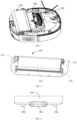
- the sweeping device includes a housing 100, a driving assembly 200, and a crawler-type cleaning cloth 300.
- the housing 100 is a mounting carrier for various components of the sweeping device. Unless otherwise specified, all components of the sweeping device mentioned below are directly or indirectly mounted in the housing 100.
- the driving assembly 200 and the crawler-type cleaning cloth 300 are both mounted in the housing 100.
- the driving assembly 200 is configured to drive the sweeping device to move on a surface to be cleaned.
- the crawler-type cleaning cloth 300 is configured to sweep the surface to be cleaned.
- the driving assembly 200 and the crawler-type cleaning cloth 300 each has an independent power member, so as to provide power for their respective autonomous rotations.
- the crawler-type cleaning cloth 300 includes a first transmission shaft 301, a second transmission shaft 302, a first power member 303, and a cleaning member 304.
- the first transmission shaft 301 and the second transmission shaft 302 are arranged in parallel.
- the cleaning member 304 is arranged in a ring belt shape to be wound around the first transmission shaft 301 and the second transmission shaft 302.
- the first power member 303 may include an electric motor, a gearbox, etc.
- the first power member 303 is in transmission connected to the first transmission shaft 301 and/or the second transmission shaft 302 to provide power for the rotation of the first transmission shaft 301 and the second transmission shaft 302.
- the cleaning member 304 can be driven to operate to clean the surface to be cleaned.
- the cleaning member 304 is made of a flexible material, which may be a sponge or cloth material, a mop made of silicone or rubber, or a material layer with adsorption properties.
- a mop or sponge When a mop or sponge is used as the cleaning member 304, the mop or sponge comes into contact with the surface to be cleaned, thereby removing stains or debris on the surface to be cleaned.
- the cleaning member 304 is made of a material layer with adsorption properties, the material layer is in contact with the surface to be cleaned, thereby adsorbing stains or debris on the surface to be cleaned.
- Stains include but are not limited to traces of various liquid substances remaining on the surface to be cleaned, such as oil stains, etc.
- Debris includes various types of solid dirt, such as paper scraps, hair or dust.
- the cleaning member 304 When the cleaning member 304 cleans the surface to be cleaned, the cleaning member 304 is in contact with and slides relative to the surface to be cleaned, thereby generating friction between the cleaning member 304 and the surface to be cleaned. In other words, the cleaning member 304 generates a force on the surface to be cleaned, and the force can exert a traction effect on the sweeping device.
- the configuration of the material of the cleaning member 304 and a contact area between the cleaning member and the surface to be cleaned, etc., has an influence on the magnitude of the above-mentioned force.
- the driving assembly 200 adopts a wheel-type traveling mechanism, including a first driving wheel 201, a second driving wheel 203, and a second power member 205.
- the first driving wheel 201 and the second driving wheel 203 can be arranged coaxially, one of the first driving wheel 201 and the second driving wheel 203 serves as a driving wheel to obtain the power of the second power member 205 to generate rotation, and the other of the first driving wheel 201 and the second driving wheel 203 serves as a driven wheel to rotate following the rotation of the driving wheel.
- the axial connection between the first driving wheel 201 and the second driving wheel 203 is parallel to the first transmission shaft 301 and the second transmission shaft 302 of the crawler-type cleaning cloth 300.
- first driving wheel 201 and the second driving wheel 203 may be provided separately and are respectively connected to one second power member 205 in transmission to obtain rotational power.
- the second power member 205 may include an electric motor, a gearbox and other components, and may provide power for the rotation of the first driving wheel 201 and the second driving wheel 203.
- Friction is generated between the first driving wheel 201 and the second driving wheel 203 and the surface to be cleaned, that is, the first driving wheel 201 and the second driving wheel 203 exert force on the surface to be cleaned, and the force exerts a traction effect on the sweeping device.
- the surface to be cleaned is substantially horizontal
- the sum of the force vectors generated by the driving assembly 200 and the crawler-type cleaning cloth 300 on the surface to be cleaned is used as a driving force to drive the sweeping device to move relative to the surface to be cleaned, so as to determine a movement direction of the sweeping device relative to the surface to be cleaned, such as forward, stationary, backward, etc. relative to the surface to be cleaned.
- the positive Y-axis direction is taken as a forward direction, which points to the front of the sweeping device
- the negative Y-axis direction is taken as a backward direction, which points to the rear of the sweeping device.
- the surface to be cleaned provides a reaction force in the negative direction of the Y-axis to the sweeping device, so that the sweeping device moves backward relative to the surface to be cleaned.
- the force vector provided by the sweeping device to the surface to be cleaned is approximately zero, the sweeping device is stationary relative to the surface to be cleaned.
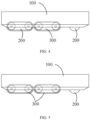
- FIG. 3 shows a sweeping device provided by an embodiment, which includes two groups of driving assemblies 200, which are respectively located at the front and rear sides of the crawler-type cleaning cloth 300. It should be understood that each group of driving assemblies 200 has the independent power member respectively.
- FIG. 4 shows a sweeping device provided by an embodiment, in which one group of driving assemblies 200 is a crawler-type traveling mechanism, that is, the driving assembly 200 is a combination of a wheel-type traveling mechanism and a crawler-type traveling mechanism.
- the specific structure of the crawler-type traveling mechanism can be referred to the crawler-type cleaning cloth 300 in the above embodiment, the difference between the crawler-type traveling mechanism and the cleaning member 304 in the crawler-type cleaning cloth 300 is only that the corresponding components in the crawler-type traveling mechanism are mainly used for walking, not mainly used for sweeping, so that a structure more suitable for realizing the walking function can be adopted.
- the present application does not limit the number of crawler-type cleaning clothes 300.
- the sweeping device includes two groups of crawler-type cleaning clothes 300, and the two groups of crawler-type cleaning clothes 300 are arranged adjacently.
- the driving assembly 200 is disposed on a front side or a rear side of the crawler-type cleaning clothes 300. It should be understood that each group of crawler-type cleaning clothes 300 has the independent power member, respectively.
- the crawler-type cleaning clothes 300 may be configured to be liftedand lowered relative to the housing 100.
- a lifting mechanism may include a motor, and a transmission mechanism such as gears or slide rails, etc.
- the motor is provided on the housing 100, and the transmission mechanism is in transmission connection with the motor and the crawler-type cleaning cloth 300.
- the crawler-type cleaning cloth 300 can be lifted and lowered relative to the housing 100 with the help of the motor, that is, the crawler-type cleaning cloth 300 can be lifted and lowered relative to the surface to be cleaned. With such an arrangement, the crawler-type cleaning cloth 300 can be separated from the surface to be cleaned to meet the needs of specific usage scenarios.
- the driving assembly 200 is provided at a middle position of a bottom portion of the housing 100. Positioning the driving assembly 200 in the middle position allows the driving assembly 200 to provide better driving force for the sweeping device and improve the capability of the sweeping device to cross obstacles and get out of the way.
- the crawler-type cleaning cloth 330 is provided adjacent to one side of the driving assembly 200. Compared with the configuration with a larger distance, such an adjacent configuration allows the sweeping device to have a larger continuous contact area with the surface to be cleaned, so that the sweeping device has better capability to cross obstacles and get out of the way when facing obstacles such as depressions.
- the crawler-type cleaning cloth 300 has a larger contact area, and when the sweeping device faces obstacles such as depressions, it has greater power to assist in crossing obstacles and getting out of the way.
- the crawler-type cleaning cloth 300 is located behind the driving assembly 200, and a projection of the crawler-type cleaning cloth 300 on a horizontal plane is at least partially located outside ta projection of the housing 100 on the horizontal plane.
- the crawler-type cleaning cloth 300 extends beyond a range covered by the housing 100, so that the crawler-type cleaning cloth 330 has a larger cleaning area, thereby improving the cleaning efficiency.
- the sweeping device faces obstacles such as depressions, it has greater power to assist in crossing obstacles and getting out of the way.
- an outer end of the first driving wheel 201 is coplanar with a left end of the crawler-type cleaning cloth 300, more specifically, the outer end of the first driving wheel 201 is coplanar with a left end of the cleaning member 304.
- An outer end of the second driving wheel 203 is coplanar with a right end of the crawler-type cleaning cloth 300, more specifically, the outer end of the second driving wheel 203 is coplanar with a right end of the cleaning member 304.
- a distance between the outer end of the first driving wheel 201 and the outer end of the second driving wheel 203 is equal to a distance between two ends of the cleaning member 304.
- the driving assembly 200 can deflect within a preset range of deflection angles relative to the Y-axis direction to change a traveling direction of the sweeping device. Therefore, the driving assembly 200 further includes a power member for deflecting the first driving wheel 201 and the second driving wheel 203.
- a large opening is provided at a position where the first driving wheel 201 and the second driving wheel 203 are provided in the housing 100, so as to provide sufficient space for the deflection of the first driving wheel 201 and the second driving wheel 203 to avoid interference with the housing 100 during deflection.
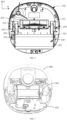
- a cleaning pump 101 and a clean water tank 105 are further mounted in the housing 100, and a spraying port 103 is provided at the bottom portion of the housing 100.
- a water inlet of the cleaning pump 101 is in communication with the clean water tank 105, and a water outlet of the cleaning pump 101 is in communication with the spraying port 103.
- the spraying port 103 is provided adjacent to the crawler-type cleaning cloth 300.
- a plurality of spraying ports 103 may be provided, and the plurality of spraying ports 103 may be evenly spaced along tan axial direction parallel to the crawler-type cleaning cloth 300.
- the cleaning pump 101 can pump out the cleaning liquid from the clean water tank 105 and spray the cleaning liquid to the surface to be cleaned through the spraying port 103.
- the surface to be cleaned is first wetted and impregnated by the cleaning liquid, and then cleaned by the crawler-type cleaning cloth 300 to improve the cleaning effect of the crawler-type cleaning cloth 300 on the surface to be cleaned.
- the sweeping device is further provided a sewage tank 107 mounted in the housing 100, and a scraping strip 305 is provided facing the crawler-type cleaning cloth 300.
- the crawler-type cleaning cloth 300 will mix the cleaning fluid with stains and debris on the surface to be cleaned to form sewage.
- the scraping strip 305 the sewage attached to the crawler-type cleaning cloth 300 can be scraped and separated to the sewage tank 107 to be collected and temporarily stored.
- the sewage in the sewage tank 107 can be treated periodically.
- both the sewage tank 107 and the clean water tank 105 are detachably mounted in the housing 100 to facilitate the replenishment of cleaning liquid and the treatment of sewage.
- the scraping strip 305 is configured to be controllably telescopically arranged relative to the crawler-type cleaning cloth 300. Therefore, when the crawler-type cleaning cloth 300 needs to be scraped, the scraping strip 305 extend out to abut against and scrape the crawler-type cleaning cloth 300. When the crawler-type cleaning cloth 300 does not need to be scraped, the scraping strip 305 retracts and is separated from the crawler-type cleaning cloth 300.
- FIG. 9 shows a block diagram of the sweeping device according to an embodiment.
- the sweeping device includes a detection assembly 400 configured to detect environmental information or operating information of the sweeping device, and a control assembly 500 that is communicatively connected to the driving assembly 200, the crawler-type cleaning cloth 300 and the detection assembly 400.
- the detection assembly 400 may include one or more of an infrared sensor, an inertial sensor (IMU), an angle sensor, an optical flow sensor, a camera, a LIDAR, a wheel odometer, a visual odometer, and a laser odometer that are disposed at a suitable location on the housing 100.
- the environmental information detected by the detection assembly 400 includes but is not limited to a distance between the sweeping device and a target object in the working environment, a motion state of the target object, and a three-dimensional data of a shape of the target object, etc.
- the environmental information can be presented as static pictures or dynamic videos.
- the operating information of the sweeping device detected by the detection assembly 400 includes but is not limited to a rotation speed of the driving assembly 200 of the sweeping device, a deflection angle of the driving assembly 200, a rotation speed of the crawler-type cleaning cloth 300, a lifting state of the crawler-type cleaning cloth 300 relative to the housing 100, and a telescopic state of the scraping strip. 305, etc.
- the information obtained by the detection assembly 400 can be used to directly or indirectly determine whether the sweeping device travels normally. It should be understood that during normal traveling, the sweeping device can be better maintained in the cleaning state to continuously and effectively clean the surface to be cleaned. If the sweeping device travels abnormally, or is about to move abnormally, the continuity and stability of the cleaning state of the sweeping device may be affected, so that the expected cleaning effect cannot be achieved.
- Abnormal traveling includes the traveling state of the sweeping device in the following situations: the sweeping device is blocked by obstacles, the driving assembly 200 is stuck, the driving assembly 200 is suspended, or the driving assembly 200 slips.
- the first situation is that the impact of obstacles on the traveling of the sweeping device can be basically ignored.
- the sweeping device in normal traveling with the capability to cross the obstacle can cross the obstacle.
- the traveling state may be slightly affected, which is different from normal traveling, but after crossing the obstacle, the sweeping device can automatically restore to the normal traveling state to maintain the normal cleaning state. It should be understood that in this case, if the movement mode of the driving assembly 200 and the crawler-type cleaning cloth 300 of the sweeping device is changed, so that the sweeping device has a better capability to cross obstacles than during traveling normally, and the obstacle can also be crossed.
- the second situation is that the impact of obstacles on the traveling of the sweeping device is controllable. It is necessary to change the movement mode of the driving assembly 200 and the crawler-type cleaning cloth 300 of the sweeping device, so that the sweeping device has a better obstacle-crossing capability than during traveling normally to cross the obstacle, so as to achieve normal traveling and maintain normal cleaning status.
- the third situation is that the obstacle has exceeded the obstacle-crossing capability of the sweeping device, ultimately resulting in the sweeping device being in a trapped state. Unless avoidance or manual intervention is chosen, the sweeping device is unable to get out of the trap on its own.
- the obstacle height demarcation thresholds in the three situations can be represented by A0 and A1, where A0 is less than A1.
- A0 is less than or equal to A0
- the obstacle height is between A0 and A1 belongs to the second situation above.
- the obstacle height is greater than or equal to A1 it belongs to the third situation mentioned above.
- the driving assembly 200 is stuck, the driving assembly 200 is suspended, or the driving assembly 200 slips due to various abnormal factors that cause the driving assembly 200 to be unable to provide normal driving force, thereby being unable to drive the sweeping device to move relative to the surface to be cleaned.
- the driving assembly 200 may often become stuck.
- the obstacle is a depression with a certain depth and area
- the sweeping device cannot pass through the depression and the driving assembly 200 may be suspended in the depression.
- the sweeping device may not be able to move normally due to the driving assembly 200 slipping on the oil stains.
- the control assembly 500 is configured to receive the detection information provided by the detection assembly 400, and then control the operation of relevant components of the sweeping device according to a preset algorithm, such as controlling the driving assembly 200 and the crawler-type cleaning cloth 300 to operate according to corresponding movement modes.
- the control assembly 500 may include a processor, a memory, etc.
- a processor may include one or more processing cores. The processor uses various interfaces and lines to connect various components of the sweeping device, and executes various functions of the sweeping device and processes data by running or executing instructions, programs, code sets or sets of instructions stored in the memory and by calling up data stored in the memory.
- the processor can be implemented in at least one hardware form among digital signal processing (Digital Signal Processing, DSP), field-programmable gate array (Field-Programmable Gate Array, FPGA), and programmable logic array (Programmable Logic Array, PLA).
- the processor can integrate one or a combination of a central processing unit (Central Processing Unit, CPU), a graphics processing unit (Graphics Processing Unit, GPU), a modem, etc.
- the central processing unit mainly handles the operating system, user interface and application programs.
- the graphics processing unit is configured to render and draw the display content.
- the modem is configured to process wireless communications. It should be understood that the above-mentioned modem may not be integrated into the processor and may be implemented solely through a communication chip.
- the control assembly 500 may be integrated into the housing 100.
- the control assembly 500 may be provided on a server, and the server remotely receives the detection information provided by the detection assembly 400, processes the detection information, and makes corresponding responses and executions.
- FIGS. 10 to 15 The following is an exemplary description of a method for controlling a sweeping device provided by the present application with reference to FIGS. 10 to 15 . It should be understood that the sweeping device in FIGS. 10 to 15 is only an example of the structure, and it does not mean that the control method provided in the present application can only be limited to the sweeping device with these structures.
- rotation directions of the driving assembly 200 and the crawler-type cleaning cloth 300 are opposite.
- the driving assembly 200 and the crawler-type cleaning cloth 300 are each powered by a respective power member to generate rotation.
- An arrow located in an upper left of the sweeping device indicates a movement direction of the sweeping device, and a direction pointing to the left is defined as a forward direction, that is, the sweeping device moves forward relative to the surface to be cleaned.
- An arrow located on the driving assembly 200 indicates the rotation direction of the driving assembly 200.
- An arrow located on the crawler-type cleaning cloth 300 indicates the rotation direction of the crawler-type cleaning cloth 300.
- An arrow F 1 located between the driving assembly 200 and the surface to be cleaned indicates a forward force provided by the surface to be cleaned to the driving assembly 200.
- An arrow F2 located between the crawler-type cleaning cloth 300 and the surface to be cleaned indicates a backward force provided by the surface to be cleaned to the crawler-type cleaning cloth 300. Unless otherwise specified, the arrows in the following figures have the same meaning as the above description.
- the forward force F 1 provided by the surface to be cleaned to the driving assembly 200 is greater than the backward force F2 provided by the surface to be cleaned to the crawler-type cleaning cloth 300, that is, the sum of the force vectors provided by the driving assembly 200 and the crawler-type cleaning cloth 300 to the surface to be cleaned points forward, so that the sweeping device can move forward relative to the surface to be cleaned.
- the driving assembly 200 drives the sweeping device to move at a speed V1 relative to the surface to be cleaned.
- the crawler-type cleaning cloth 300 rotates autonomously and a side of the crawler-type cleaning cloth 300 that is in contact with the surface to be cleaned moves at a speed V0 relative to the surface to be cleaned.
- a moving speed of the side of the crawler-type cleaning cloth 300 that is in contact with the surface to be cleaned relative to the surface to be cleaned is that V0 plus V1.
- the reverse rotation of the two increases the rotation speed of the crawler-type cleaning cloth 300 relative to the surface to be cleaned, thereby achieving a better cleaning effect.
- the rotation directions of the two crawler-type cleaning clothes 300 can be opposite. As shown in FIG. 11 , the rotation directions of the two crawler-type cleaning clothes 300 at the front and rear are opposite. It should be pointed out that each of the two crawler-type cleaning clothes 300 are powered by a respective power member to generate autonomous rotation in opposite directions. Therefore, the surface to be cleaned provides a backward force F2 to the crawler-type cleaning cloth 300 located at the rear and a forward force F3 to the crawler-type cleaning cloth 300 located in the front. The sweeping device moves forward relative to the surface to be cleaned under the resultant force of the three vectors of forward force F 1, backward force F2 and forward force F3.
- the control assembly 500 receives the detection information and controls the driving assembly 200 or the crawler-type cleaning cloth 300 to change the movement mode to increase the force vector provided by driving assembly 200 and the crawler-type cleaning cloth 300 to the surface to be cleaned.
- the force vector provided by the surface to be cleaned to the sweeping device also increases.
- the sweeping device can have greater obstacle-crossing capability, or have a varied travel strategy, so that the sweeping device can autonomously get rid of abnormal traveling or avoid factors that will cause abnormal traveling, and facilitate restoring or maintaining normal traveling states, in order to produce the expected sweeping effect on the surface to be cleaned.
- the crawler-type cleaning cloth 300 is stopped from rotating autonomously to increase the force vector between the driving assembly 200, the crawler-type cleaning cloth 300 and the surface to be cleaned. Since the backward force F2 provided by the surface to be cleaned to the crawler-type cleaning cloth 300 removes after the crawler-type cleaning cloth 300 stops rotating, the force vector between the driving assembly 200, the crawler-type cleaning cloth 300 and the surface to be cleaned is the forward force F 1.
- the forward force F 1 becomes larger than the resultant force of the forward force F 1 and the backward force F2 in the operating mode shown in FIG. 10 .
- the crawler-type cleaning cloth 300 can stop rotating autonomously to cross the obstacle.
- the obstacle disappears the normal traveling state can be restored, and the rotation directions of the driving assembly 200 and the crawler-type cleaning cloth 300 are opposite again.
- the crawler-type cleaning cloth 300 stops rotating autonomously, it means that the first power member 303 in the crawler-type cleaning cloth 300 stops outputting power. Whether the crawler-type cleaning cloth 300 still rotates relative to the surface to be cleaned is determined by the resultant force between the surface to be cleaned and the crawler-type cleaning cloth 300.
- This force includes at least a static friction force between the surface to be cleaned and the crawler-type cleaning cloth 300 and a braking force of the crawler-type cleaning cloth 300.
- the crawler-type cleaning cloth 300 adopts a braking mode, the crawler-type cleaning cloth 300 itself has a braking force to inhibit rotation.
- the crawler-type cleaning cloth 300 does not rotate, but moves relative to the surface to be cleaned as the sweeping device continues to move forward.
- the crawler-type cleaning cloth 300 itself is not braked, in the case that the static friction between the surface to be cleaned and the crawler-type cleaning cloth 300 is not large enough, the crawler-type cleaning cloth 300 will also stop rotating, and will move relative to the surface to be cleaned as the sweeping device continues to move forward.
- the sweeping device will passively follow the driving assembly 200 to rotate in the same direction while continuing to move forward.
- the force vector between the crawler-type cleaning cloth 300 and the surface to be cleaned is greater than that when the driving assembly 200 and the crawler-type cleaning cloth 300 rotate in opposite directions.
- the crawler-type cleaning cloth 300 may be lifted to be separated from the surface to be cleaned to increase the force vector between the driving assembly 200, the crawler-type cleaning cloth 300 and the surface to be cleaned. Since the backward force F2 provided by the surface to be cleaned to the crawler-type cleaning cloth 300 disappears after the crawler-type cleaning cloth 300 is separated from the surface to be cleaned, the force vector between the driving assembly 200, the crawler-type cleaning cloth 300 and the surface to be cleaned is the forward force F1, This forward force F1 becomes larger than the resultant force of the forward force F 1 and the backward force F2 in the operating mode shown in FIG. 10 . In this case, whether the crawler-type cleaning cloth 300 still rotates autonomously can be flexibly determined based on other factors.
- the crawler-type cleaning cloth 300 can be lifted to be separated from the surface to be cleaned to cross the obstacle.
- the normal traveling state can be restored, and the crawler-type cleaning cloth 300 can be in contact with the surface to be cleaned again.
- the rotation direction of the driving assembly 200 can be the same as the rotation direction of the crawler-type cleaning cloth 300 to increase the force vector between the driving assembly 200, the crawler-type cleaning cloth 300 and the surface to be cleaned.
- the rotation direction of the crawler-type cleaning cloth 300 is changed, so that the rotation direction of the driving assembly 200 is the same as the rotation direction of the crawler-type cleaning cloth 300.
- the backward force F2 provided by the surface to be cleaned to the crawler-type cleaning cloth 300 becomes the forward force F2. Therefore, the force vector between the driving assembly 200, the crawler-type cleaning cloth 300 and the surface to be cleaned is the sum of the forward force F 1 and the forward force F2, which becomes larger compared to that in the operating mode in FIG. 10 .
- the crawler-type cleaning cloth 300 can be caused to change the rotation direction to be the same as the rotation direction of the driving assembly 200, so that the sweeping device can get rid of or avoid abnormal traveling.
- the rotation direction of the driving assembly 200 may be changed, so that the rotation direction of the driving assembly 200 is the same as the rotation direction of the crawler-type cleaning cloth 300.
- the forward force F 1 provided by the surface to be cleaned to the driving assembly 200 becomes the backward force F1. Therefore, the force vector between the driving assembly 200, the crawler-type cleaning cloth 300 and the surface to be cleaned is the sum of the backward force F1 and the backward force F2.
- this force vector becomes larger and in the opposite direction, so that the sweeping device can be moved backward relative to the surface to be cleaned.
- the detection assembly 400 detects that there is an obstacle on the path of the sweeping device and it belongs to the third situation of being blocked by the obstacle mentioned above, or it detects that the driving assembly 200 is about to be or has been stuck, when the driving assembly 200 is about to or has been suspended or the driving assembly 200 is about to slip or has slipped, the driving device 200 can be caused to change the rotation direction to be the same as the rotation direction of the crawler-type cleaning cloth 300, so that the sweeping device can get rid of or avoid abnormal traveling.
- the force vector between both the driving assembly 200 and the crawler-type cleaning cloth 300 and the surface to be cleaned may also be increased by reducing the deflection angle. Since the deflection angle is reduced, the component force along the front-to-back direction parallel to the housing 100 of the sweeping device will become larger, thereby increasing the force vector between the driving assembly 200, the crawler-type cleaning cloth 300 and the surface to be cleaned, so that the sweeping device can move forward or backward. It should be understood that this method of changing the movement mode of the driving assembly 200 by changing the deflection angle can be combined with the other methods of changing the movement mode of the driving assembly 200 or the crawler-type cleaning cloth 300 as needed.
- the force vectors between the driving assembly 200, the crawler-type cleaning cloth 300 and the surface to be cleaned are different.
- the force vector in the movement mode shown in FIG. 12 is less than that in the movement mode shown in FIG. 14 . Therefore, in some embodiments, different abnormality levels can also be preset according to a height of the obstacle. Different abnormality levels require the sweeping device to have different obstacle-crossing capability. According to the corresponding abnormality level, the corresponding change in the movement mode of the driving assembly 200 or the crawler-type cleaning cloth 300 is adapted to adjust the magnitude of the force vector between the sweeping device and the surface to be cleaned, so as to have different obstacle-crossing capabilities.
- a first abnormality level and a second abnormality level are preset according to the height of the obstacle, and the height of the obstacle at the first abnormality level is lower than the height of the obstacle at the second abnormality level.
- the movement mode of the driving assembly or the crawler-type cleaning cloth is changed to provide a first force vector to the surface to be cleaned, such as the force vector of the movement mode shown in FIG. 12 .
- the movement mode of the driving assembly or the crawler-type cleaning cloth is changed to provide a second force vector to the surface to be cleaned, such as the force vector of the movement mode shown in FIG. 14 .
- the cleaning pump 101 sprays cleaning liquid to the surface to be cleaned through the spraying port 103.
- the surface to be cleaned is first wetted and impregnated by the cleaning liquid, and then cleaned by the crawler-type cleaning cloth 300.
- the crawler-type cleaning cloth 300 mixes cleaning fluid with stains and debris on the surface to be cleaned to form sewage.
- the scraping strip 305 scrapes and separates the sewage attached to the crawler-type cleaning cloth 300 to the sewage tank 107 to be collected and temporarily stored.
- the crawler-type cleaning cloth 300 needs to rotate in a specific direction, such as the movement mode shown in FIG.
- the scraping strip 305 can scrape and separate the sewage on the crawler-type cleaning cloth 300 to the sewage tank 107.
- the crawler-type cleaning cloth 300 changes direction, such as the movement mode shown in FIG. 14 , the sewage on the crawler-type cleaning cloth 300 will be scraped off by the scraping strip 305 and remain on the surface to be cleaned, which will affect the cleaning effect.
- the cleaning pump 101 can be turned off to stop spraying cleaning fluid on the surface to be cleaned.
- the cleaning pump 101 does not need to be turned off.
- the crawler-type cleaning cloth 300 in the case that the crawler-type cleaning cloth 300 does not rotate, the scraping strip 305 will not scrape the sewage on the crawler-type cleaning cloth 300 to the surface to be cleaned, and the cleaning pump 101 does not need to be turned off.
- the crawler-type cleaning cloth 300 in the movement mode shown in FIG. 15 , the crawler-type cleaning cloth 300 does not change due to a steering direction, and there is no need to turn off the cleaning pump 101.
- the scraping strip 305 when the movement mode of the crawler-type cleaning cloth 300 is changed, in order to prevent the sewage on the crawler-type cleaning cloth 300 from being scraped off by the scraping strip 305 and left on the surface to be cleaned, the scraping strip 305 may be controlled to retract and be separated from the crawler-type cleaning cloth 300.
- the scraping strip 305 in the movement mode as shown in FIG. 10 , the scraping strip 305 may be controlled to extend out to scrape the sewage on the crawler-type cleaning cloth 300.
- the scraping strip 305 In the movement mode as shown in FIG. 14 , the scraping strip 305 may be controlled to retract and be separated from the crawler-type cleaning cloth 300.
Landscapes
- Electric Vacuum Cleaner (AREA)
- Cleaning In General (AREA)
Applications Claiming Priority (3)
| Application Number | Priority Date | Filing Date | Title |
|---|---|---|---|
| CN202110501250.3A CN113208507B (zh) | 2021-05-08 | 2021-05-08 | 清洁设备控制方法、装置及清洁设备 |
| CN202111343423.XA CN114027748B (zh) | 2021-11-13 | 2021-11-13 | 移动机器人行走控制方法 |
| PCT/CN2022/090349 WO2022237587A1 (fr) | 2021-05-08 | 2022-04-29 | Procédé de commande de dispositif de nettoyage et dispositif de nettoyage |
Publications (2)
| Publication Number | Publication Date |
|---|---|
| EP4335344A1 true EP4335344A1 (fr) | 2024-03-13 |
| EP4335344A4 EP4335344A4 (fr) | 2026-03-11 |
Family
ID=83245367
Family Applications (1)
| Application Number | Title | Priority Date | Filing Date |
|---|---|---|---|
| EP22806555.3A Pending EP4335344A4 (fr) | 2021-05-08 | 2022-04-29 | Procédé de commande de dispositif de nettoyage et dispositif de nettoyage |
Country Status (4)
| Country | Link |
|---|---|
| US (1) | US20240252011A1 (fr) |
| EP (1) | EP4335344A4 (fr) |
| JP (1) | JP2024516314A (fr) |
| CN (1) | CN115087383A (fr) |
Cited By (1)
| Publication number | Priority date | Publication date | Assignee | Title |
|---|---|---|---|---|
| CN121242445A (zh) * | 2025-12-03 | 2026-01-02 | 麦悦未来智能科技(苏州)有限公司 | 清洁盘、清洁基站和清洁控制方法 |
Families Citing this family (2)
| Publication number | Priority date | Publication date | Assignee | Title |
|---|---|---|---|---|
| CN118924179B (zh) * | 2024-09-06 | 2025-10-10 | 追觅创新科技(苏州)有限公司 | 自移动的清洁设备 |
| CN120155598A (zh) * | 2025-05-16 | 2025-06-17 | 济南铸锻所检验检测科技有限公司 | 一种金属卷板纵剪机 |
Family Cites Families (28)
| Publication number | Priority date | Publication date | Assignee | Title |
|---|---|---|---|---|
| CN203234684U (zh) * | 2013-05-21 | 2013-10-16 | 高率博 | 智能地面清洁设备 |
| KR102193998B1 (ko) * | 2014-07-15 | 2020-12-22 | 엘지전자 주식회사 | 로봇 청소용 걸레 어셈블리 및 이를 구비한 로봇 청소기 |
| KR101678443B1 (ko) * | 2015-09-23 | 2016-12-06 | 엘지전자 주식회사 | 로봇 청소기 |
| CN206630556U (zh) * | 2016-12-20 | 2017-11-14 | 南京工程学院 | 一种家居清洁机器人 |
| CN106618402B (zh) * | 2016-12-28 | 2019-08-13 | 圆融健康科技(深圳)有限公司 | 扫地机器人 |
| CN106821152B (zh) * | 2017-01-17 | 2022-03-01 | 郑明珠 | 智能滚筒抹布擦地扫地清洁机器人 |
| DE102017126414A1 (de) * | 2017-11-10 | 2019-05-16 | Vorwerk & Co. Interholding Gmbh | Feuchtreinigungseinrichtung zur Reinigung einer Fläche |
| WO2020125489A1 (fr) * | 2018-12-21 | 2020-06-25 | 苏州宝时得电动工具有限公司 | Robot nettoyeur et son procédé de commande, et système de traitement de sol |
| EP3900602A4 (fr) * | 2018-12-21 | 2022-09-14 | Positec Power Tools (Suzhou) Co., Ltd | Robot de nettoyage et procédé de commande |
| US12329337B2 (en) * | 2018-12-21 | 2025-06-17 | Positec Power Tools (Suzhou) Co., Ltd. | Robot cleaning system, base station, and control method |
| CN209564072U (zh) * | 2018-12-21 | 2019-11-01 | 宁波富佳实业股份有限公司 | 一种具有超声波震荡功能的清洁设备 |
| WO2020125491A1 (fr) * | 2018-12-21 | 2020-06-25 | 苏州宝时得电动工具有限公司 | Robot de nettoyage et procédé de commande |
| CN110403539B (zh) * | 2019-08-16 | 2022-06-03 | 云鲸智能科技(东莞)有限公司 | 清洁机器人的清洁控制方法、清洁机器人以及存储介质 |
| CN110693403A (zh) * | 2019-09-25 | 2020-01-17 | 牛桂森 | 履带式带水桶电动拖把 |
| CN110584547B (zh) * | 2019-10-18 | 2021-11-02 | 尚科宁家(中国)科技有限公司 | 一种扫地机器人的清洁方法及清洁系统 |
| CN111227728B (zh) * | 2020-01-15 | 2021-06-22 | 迟金磊 | 一种履带式自清洗拖地机套件 |
| CN111407192A (zh) * | 2020-03-20 | 2020-07-14 | 珠海市一微半导体有限公司 | 一种清洁机器人的工作控制方法及系统 |
| CN212996284U (zh) * | 2020-03-25 | 2021-04-20 | 科沃斯机器人股份有限公司 | 自主移动设备 |
| CN213097715U (zh) * | 2020-04-01 | 2021-05-04 | 追创科技(苏州)有限公司 | 一种履带式的清洁机构、清洁装置、扫地机 |
| CN111419122A (zh) * | 2020-04-02 | 2020-07-17 | 无锡职业技术学院 | 一种智能自动扫地拖地机器人 |
| CN114098543B (zh) * | 2020-08-26 | 2024-01-09 | 宝时得科技(中国)有限公司 | 拖地机器人及其控制方法、控制装置和存储介质 |
| CN112535432B (zh) * | 2020-08-30 | 2024-07-16 | 杭州匠龙机器人科技有限公司 | 一种带清洗座的清洁机器人 |
| CN112535440B (zh) * | 2020-08-30 | 2024-07-16 | 杭州匠龙机器人科技有限公司 | 一种带清洗座的清洁机器人 |
| CN214208257U (zh) * | 2020-10-28 | 2021-09-17 | 杭州匠龙机器人科技有限公司 | 一种滚拖模块及其清洁机器人 |
| CN112806924A (zh) * | 2021-02-04 | 2021-05-18 | 南京抒微智能科技有限公司 | 一种阻滞式拖地机器人 |
| CN113208507B (zh) * | 2021-05-08 | 2022-11-22 | 深圳甲壳虫智能有限公司 | 清洁设备控制方法、装置及清洁设备 |
| CN114355938A (zh) * | 2021-12-31 | 2022-04-15 | 深圳甲壳虫智能有限公司 | 扫地机器人测障方法及扫地机器人 |
| CN114287835A (zh) * | 2022-01-12 | 2022-04-08 | 深圳甲壳虫智能有限公司 | 自移动机器人 |
-
2022
- 2022-04-29 CN CN202280001551.2A patent/CN115087383A/zh active Pending
- 2022-04-29 EP EP22806555.3A patent/EP4335344A4/fr active Pending
- 2022-04-29 JP JP2023568416A patent/JP2024516314A/ja active Pending
- 2022-04-29 US US18/289,995 patent/US20240252011A1/en not_active Abandoned
Cited By (1)
| Publication number | Priority date | Publication date | Assignee | Title |
|---|---|---|---|---|
| CN121242445A (zh) * | 2025-12-03 | 2026-01-02 | 麦悦未来智能科技(苏州)有限公司 | 清洁盘、清洁基站和清洁控制方法 |
Also Published As
| Publication number | Publication date |
|---|---|
| EP4335344A4 (fr) | 2026-03-11 |
| CN115087383A (zh) | 2022-09-20 |
| JP2024516314A (ja) | 2024-04-12 |
| US20240252011A1 (en) | 2024-08-01 |
Similar Documents
| Publication | Publication Date | Title |
|---|---|---|
| EP4335344A1 (fr) | Procédé de commande de dispositif de nettoyage et dispositif de nettoyage | |
| EP3093413B1 (fr) | Robot de nettoyage de piscine | |
| EP4292503A1 (fr) | Dispositif de nettoyage automatique | |
| WO2020143291A1 (fr) | Procédé, dispositif et appareil permettant de commander un robot laveur et support de stockage | |
| CN113208507B (zh) | 清洁设备控制方法、装置及清洁设备 | |
| KR102188797B1 (ko) | 로봇 청소기 및 그 제어 방법 | |
| EP4292492A1 (fr) | Dispositif de nettoyage automatique | |
| WO2022237587A1 (fr) | Procédé de commande de dispositif de nettoyage et dispositif de nettoyage | |
| CN117502980A (zh) | 自移动清洁设备、控制方法及清洁系统 | |
| CN111466827B (zh) | 清洁机器人及其清洁模式 | |
| KR20230002217A (ko) | 로봇청소기 및 그 제어방법 | |
| CN113749576B (zh) | 清洁装置及其控制方法 | |
| CN223275392U (zh) | 清洁机器人及拖洗组件 | |
| CN118924178A (zh) | 自移动的清洁设备 | |
| CN114027748A (zh) | 移动机器人行走控制方法 | |
| CN223248120U (zh) | 清洁设备及清洁系统 | |
| CN223516285U (zh) | 清洁机器人 | |
| RU2023131465A (ru) | Способ управления чистящим устройством и чистящее устройство | |
| KR102270318B1 (ko) | 휠 슬립 방지를 위한 휠 어셈블리 구조 및 그를 이용한 이동 로봇 | |
| JP2025006510A (ja) | 床面洗浄機およびスキージ装置のリセット方法 | |
| CN120508102A (zh) | 水池清洁设备控制方法、装置、水池清洁设备及存储介质 | |
| CN116763198A (zh) | 一种辊式拖地机器人 | |
| KR20240000883U (ko) | 로봇 청소기 | |
| CN118203255A (zh) | 待清洁面的清洁方法 | |
| CN118924179A (zh) | 自移动的清洁设备 |
Legal Events
| Date | Code | Title | Description |
|---|---|---|---|
| STAA | Information on the status of an ep patent application or granted ep patent |
Free format text: STATUS: THE INTERNATIONAL PUBLICATION HAS BEEN MADE |
|
| PUAI | Public reference made under article 153(3) epc to a published international application that has entered the european phase |
Free format text: ORIGINAL CODE: 0009012 |
|
| STAA | Information on the status of an ep patent application or granted ep patent |
Free format text: STATUS: REQUEST FOR EXAMINATION WAS MADE |
|
| 17P | Request for examination filed |
Effective date: 20231204 |
|
| AK | Designated contracting states |
Kind code of ref document: A1 Designated state(s): AL AT BE BG CH CY CZ DE DK EE ES FI FR GB GR HR HU IE IS IT LI LT LU LV MC MK MT NL NO PL PT RO RS SE SI SK SM TR |
|
| DAV | Request for validation of the european patent (deleted) | ||
| DAX | Request for extension of the european patent (deleted) | ||
| RIC1 | Information provided on ipc code assigned before grant |
Ipc: A47L 11/24 20060101AFI20251114BHEP Ipc: A47L 11/28 20060101ALI20251114BHEP Ipc: A47L 11/40 20060101ALI20251114BHEP |
|
| A4 | Supplementary search report drawn up and despatched |
Effective date: 20260209 |
|
| RIC1 | Information provided on ipc code assigned before grant |
Ipc: A47L 11/24 20060101AFI20260203BHEP Ipc: A47L 11/28 20060101ALI20260203BHEP Ipc: A47L 11/40 20060101ALI20260203BHEP |