EP4335352A2 - Vorrichtungen und verfahren zur erweiterung eines arbeitskanals - Google Patents
Vorrichtungen und verfahren zur erweiterung eines arbeitskanals Download PDFInfo
- Publication number
- EP4335352A2 EP4335352A2 EP23205343.9A EP23205343A EP4335352A2 EP 4335352 A2 EP4335352 A2 EP 4335352A2 EP 23205343 A EP23205343 A EP 23205343A EP 4335352 A2 EP4335352 A2 EP 4335352A2
- Authority
- EP
- European Patent Office
- Prior art keywords
- inner member
- lumen
- extension device
- outer member
- medical device
- Prior art date
- Legal status (The legal status is an assumption and is not a legal conclusion. Google has not performed a legal analysis and makes no representation as to the accuracy of the status listed.)
- Pending
Links
Images


Classifications
-
- A—HUMAN NECESSITIES
- A61—MEDICAL OR VETERINARY SCIENCE; HYGIENE
- A61B—DIAGNOSIS; SURGERY; IDENTIFICATION
- A61B1/00—Instruments for performing medical examinations of the interior of cavities or tubes of the body by visual or photographical inspection, e.g. endoscopes; Illuminating arrangements therefor
- A61B1/00112—Connection or coupling means
- A61B1/00121—Connectors, fasteners and adapters, e.g. on the endoscope handle
- A61B1/00128—Connectors, fasteners and adapters, e.g. on the endoscope handle mechanical, e.g. for tubes or pipes
-
- A—HUMAN NECESSITIES
- A61—MEDICAL OR VETERINARY SCIENCE; HYGIENE
- A61B—DIAGNOSIS; SURGERY; IDENTIFICATION
- A61B1/00—Instruments for performing medical examinations of the interior of cavities or tubes of the body by visual or photographical inspection, e.g. endoscopes; Illuminating arrangements therefor
- A61B1/00112—Connection or coupling means
- A61B1/00119—Tubes or pipes in or with an endoscope
-
- A—HUMAN NECESSITIES
- A61—MEDICAL OR VETERINARY SCIENCE; HYGIENE
- A61B—DIAGNOSIS; SURGERY; IDENTIFICATION
- A61B1/00—Instruments for performing medical examinations of the interior of cavities or tubes of the body by visual or photographical inspection, e.g. endoscopes; Illuminating arrangements therefor
- A61B1/00064—Constructional details of the endoscope body
- A61B1/00066—Proximal part of endoscope body, e.g. handles
-
- A—HUMAN NECESSITIES
- A61—MEDICAL OR VETERINARY SCIENCE; HYGIENE
- A61B—DIAGNOSIS; SURGERY; IDENTIFICATION
- A61B1/00—Instruments for performing medical examinations of the interior of cavities or tubes of the body by visual or photographical inspection, e.g. endoscopes; Illuminating arrangements therefor
- A61B1/00064—Constructional details of the endoscope body
- A61B1/00105—Constructional details of the endoscope body characterised by modular construction
-
- A—HUMAN NECESSITIES
- A61—MEDICAL OR VETERINARY SCIENCE; HYGIENE
- A61B—DIAGNOSIS; SURGERY; IDENTIFICATION
- A61B1/00—Instruments for performing medical examinations of the interior of cavities or tubes of the body by visual or photographical inspection, e.g. endoscopes; Illuminating arrangements therefor
- A61B1/00112—Connection or coupling means
- A61B1/00121—Connectors, fasteners and adapters, e.g. on the endoscope handle
-
- A—HUMAN NECESSITIES
- A61—MEDICAL OR VETERINARY SCIENCE; HYGIENE
- A61B—DIAGNOSIS; SURGERY; IDENTIFICATION
- A61B1/00—Instruments for performing medical examinations of the interior of cavities or tubes of the body by visual or photographical inspection, e.g. endoscopes; Illuminating arrangements therefor
- A61B1/00131—Accessories for endoscopes
- A61B1/0014—Fastening element for attaching accessories to the outside of an endoscope, e.g. clips, clamps or bands
-
- A—HUMAN NECESSITIES
- A61—MEDICAL OR VETERINARY SCIENCE; HYGIENE
- A61B—DIAGNOSIS; SURGERY; IDENTIFICATION
- A61B1/00—Instruments for performing medical examinations of the interior of cavities or tubes of the body by visual or photographical inspection, e.g. endoscopes; Illuminating arrangements therefor
- A61B1/00147—Holding or positioning arrangements
-
- A—HUMAN NECESSITIES
- A61—MEDICAL OR VETERINARY SCIENCE; HYGIENE
- A61B—DIAGNOSIS; SURGERY; IDENTIFICATION
- A61B1/00—Instruments for performing medical examinations of the interior of cavities or tubes of the body by visual or photographical inspection, e.g. endoscopes; Illuminating arrangements therefor
- A61B1/012—Instruments for performing medical examinations of the interior of cavities or tubes of the body by visual or photographical inspection, e.g. endoscopes; Illuminating arrangements therefor characterised by internal passages or accessories therefor
- A61B1/018—Instruments for performing medical examinations of the interior of cavities or tubes of the body by visual or photographical inspection, e.g. endoscopes; Illuminating arrangements therefor characterised by internal passages or accessories therefor for receiving instruments
Definitions
- the present disclosure relates to the field of medical devices. Specifically, the present disclosure relates to devices, systems and methods for extending a working channel of an endoscope, such as for delivery of a stent.
- Medical devices may include predetermined lengths for parts (e . g ., a shaft of a delivery catheter, or the like) to reach into certain treatment sites within a patient and/or to be compatible with a specific auxiliary medical device (e . g ., an endoscope). Production of these medical devices with pre-determined shaft lengths may not work well with other patient treatment sites or with other auxiliary medical devices that they were not designed to be compatible with ( e . g ., other types of endoscopes or other patient body lumens).
- parts e . g ., a shaft of a delivery catheter, or the like
- a specific auxiliary medical device e . g ., an endoscope
- a medical device may be attached to an endoscope that it was not designed to be compatible with, and a length of a shaft of the medical device (e.g., a delivery catheter) may extend too far distally out of a working channel of the endoscope, rendering the device and/or system not able to operate as intended, or incorporable entirely.
- a distal tip of a catheter shaft that extends too far distally from the end of an echoendoscope may not be able to be imaged with ultrasound.
- Designing and producing multiple alternative medical devices with proper architecture to be compatible with different auxiliary medical devices may entail undue additional development and inventory costs. Additionally, there may be a loss of marketing appeal for having to purchase different versions of the same medical device simply to be compatible with multiple auxiliary devices.
- the present disclosure in various embodiments may include a device designed to connect to and work with an echoendoscope or other endoscopes.
- a shaft of a device may extend out of a distal end of the working channel of the echoendoscope a predetermined distance within a patient. This predetermined distance may be within a working range of the echoendoscope to display the treatment site to the user via ultrasound.
- a distal end length of the device that extends longer than this may be beyond the functioning range of the echoendoscope for the procedure, while an extended distal end length shorter than this may not allow for proper insertion, placement, and delivery of the stent.
- an extension device may include a tubular inner member having a lumen extending therethrough.
- a tubular outer member may include a lumen extending therethrough.
- the lumen of the outer member may be configured to receive the inner member, the outer member and inner member may be slidable relative to each other in a telescoping fashion to a desired position that corresponds to an adjustable length of the device.
- a locking assembly may be configured to fix a relative position of the outer member and the inner member with respect to each other at the desired position.
- a proximal connector may be at a proximal end of the outer member and may be configured to connect to a distal end of a first medical device.
- a distal connector may be at a distal end of the inner member and may be configured to connect to a proximal end of a second medical device.
- the lumens of the inner member and the outer member may be coaxial.
- At least one of the proximal connector and the distal connector may be a luer lock connector.
- the plurality of desired positions may include three predetermined fixed positions.
- the fixed positions may include visual indicators on the inner or outer member, or both.
- the visual indicators may include markings.
- the fixed positions may include fasteners on one or both of the inner and outer members.
- the fasteners may include a first element on the inner member and a second element on the outer member. The first and second elements may be configured to mate with each other.
- the joint may pivot such that the first longitudinal axis is at an angle of 90 degrees to 180 degrees from the second axis.
- the locking assembly may be a detent.
- the locking assembly may be a screw. The screw may lock the outer member with respect to the inner member at the desired position by engaging the inner member.
- an extension system may include an endoscope having a working channel.
- the system may include a delivery device.
- a shaft may extend distally from the delivery device and may be receivable within the working channel.
- the system may include an extension device.
- the extension device may include a tubular inner member that may have a lumen extending therethrough.
- the device may include a tubular outer member that may have a lumen extending therethrough.
- the lumen of the outer member may be configured to receive the inner member, the outer member and inner member may be slidable relative to each other in a telescoping fashion to a desired position that corresponds to an adjustable length of the extension device.
- the device may include a locking assembly configured to fix a relative position of the outer member and the inner member with respect to each other at the desired position.
- the device may include a proximal connector at a proximal end of the outer member configured to connect to a distal end of the delivery device.
- the device may include a distal connector at a distal end of the inner member configured to connect to a proximal end of the endoscope.
- the predetermined distance may be about 8 centimeters.
- the adjustable length may be a minimum of about 0 centimeters, and a maximum of about 8 centimeters.
- the lumens of the inner member and the outer member may be coaxial.
- the proximal connector may be a male luer connector and the distal connector may be a female luer connector.
- the desired position may include a plurality of predetermined fixed positions.
- the desired position may include three predetermined fixed positions.
- the joint may pivot such that the first longitudinal axis is at an angle of 90 degrees to 180 degrees from the second axis.
- the joint may include a spherical body at the distal portion of the inner member.
- the spherical body may have a first lumen therethrough that is in fluid communication with the inner lumen.
- a cupped body may be at the distal portion of the inner member and disposed about the spherical body.
- the cupped body may have a second lumen therethrough that is in fluid communication with the first lumen.
- the spherical body may be pivotable within the cupped body.
- the first lumen and the second lumen may be configured to accept the device.
- the locking assembly may be a protrusion on the inner member that corresponds to preset apertures in the outer member.
- the locking assembly may include a plurality of the preset apertures that may correspond to a plurality of the desired positions, which in turn may define a plurality of the adjustable lengths that are predetermined.
- the protrusion may include a compressible button, such that the button may be compressed to disengage the inner member from the outer member.
- the locking assembly may be a screw. The screw may lock the outer member with respect to the inner member at the desired position by engaging the inner member.
- a method of extending a length of a working channel may include inserting an endoscope having a working channel therethrough into a patient.
- a catheter may be inserted into the patient through the working channel.
- An extension device may be placed having a lumen extending therethrough about a shaft of the catheter.
- the extension device may be attached to a proximal end of the working channel.
- the catheter may be attached to a proximal end of the extension device.
- the extension device may be adjusted to a desired position that corresponds to an adjustable length of the extension device.
- the extension device may be locked at the desired position.
- the desired position may include at least one pre-determined fixed position of a locking assembly of the extension device configured to fix the adjustable length.
- the desired position may include a plurality of predetermined fixed positions.
- a plurality of channels of the extension device may be aligned with each other, such that the extension device may be placed and removed from about the shaft.
- the extension device may be rotated between an open configuration with the channels substantially aligned, and a closed configuration with the channels not substantially aligned.
- the conjunction “and” includes each of the structures, components, features, or the like, which are so conjoined, unless the context clearly indicates otherwise, and the conjunction “or” includes one or the others of the structures, components, features, or the like, which are so conjoined, singly and in any combination and number, unless the context clearly indicates otherwise.
- distal refers to the end farthest away from the medical professional when introducing a device into a patient
- proximal refers to the end closest to the medical professional when introducing a device into a patient
- numeric values are herein assumed to be modified by the term "about,” whether or not explicitly indicated.
- the term “about”, in the context of numeric values, generally refers to a range of numbers that one of skill in the art would consider equivalent to the recited value (i.e., having the same function or result). In many instances, the term “about” may include numbers that are rounded to the nearest significant figure. Other uses of the term “about” (i.e., in a context other than numeric values) may be assumed to have their ordinary and customary definition(s), as understood from and consistent with the context of the specification, unless otherwise specified.
- references in the specification to "an embodiment”, “some embodiments”, “other embodiments”, etc., indicate that the embodiment(s) described may include a particular feature, structure, or characteristic, but every embodiment may not necessarily include the particular feature, structure, or characteristic. Moreover, such phrases are not necessarily referring to the same embodiment. Further, when a particular feature, structure, or characteristic is described in connection with an embodiment, it would be within the knowledge of one skilled in the art to effect such feature, structure, or characteristic in connection with other embodiments, whether or not explicitly described, unless clearly stated to the contrary.
- Embodiments of the present disclosure include devices and systems, and methods used to extend a working channel.
- Medical devices e.g., a catheter
- a specific auxiliary medical device e.g., an endoscsope
- extension devices of the present disclosure in order to reach into other treatment sites and/or to be compatible with other auxiliary medical devices.
- a delivery catheter may be used for delivering a self-expanding drainage stent.
- the stent delivery device may be designed to connect to and work with an echoendoscope. Placement of a drainage stent within the body may be performed by insertion of a catheter carrying the stent under ultrasound guidance. The catheter is passed through the wall of a first body lumen (e . g ., gastrointestinal tract) into an adjacent lumen ( e . g ., pseudocyst) and a distal retention member of the stent is deployed. The catheter may then be retracted and a proximal retention member deployed within the GI tract (e.g., stomach).
- a first body lumen e . g ., gastrointestinal tract
- an adjacent lumen e. g ., pseudocyst
- the catheter may then be retracted and a proximal retention member deployed within the GI tract (e.g., stomach).
- Such an ultrasonic procedure may be performed using an echoendoscope in which a shaft of the delivery device is inserted through the echoendoscope.
- the working channel of an echoendoscope typically has a specific length, e . g ., about 125 cm to about 130 cm, and a delivery catheter or device will typically extend through the length of the working channel with a shaft length of about 137 cm to about 138 cm such that about 8 cm of a distal end of the catheter will extend out of a distal end of the working channel a predetermined distance within the patient.
- This predetermined distance may be within the working range of the echoendoscope to display the treatment site, including the catheter tip and stent, to the user via ultrasound.
- a distal end length of the catheter that extends longer than this may be beyond the functioning range of the echoendoscope for the procedure, while an extended distal end length shorter than this may not allow for proper insertion, placement, and delivery of the stent.
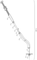
- the device 140 is connected to an echoendoscope 130 for operation by a user 150.
- the device 140 is connected to the echoendoscope 130 via a connector 142 that is a luer lock fitting, causing the device 140 to be in a locked position with respect to the echoendoscope 130.
- the user 150 may operate the echoendoscope 130 with one hand while operating the device 140 with the other hand.
- a shaft of the device 140 extends through a working channel of the echoendoscope 130 and extends from a distal end of the echoendoscope 130 a predetermined distance.
- the device 140 is in the locked position with the echoendoscope 130 and has a set shaft length such that the predetermined distance does not vary in a proximal or distal direction through movement of the device 140 with respect to the echoendoscope by the user.
- the handles 146 of the device 140 may be actuated in sequence during a procedure to deliver a stent while visualizing the distal tip of the shaft of the device with the echoendoscope.
- a medical professional may desire to use a medical device designed for a particular auxiliary medical device (e.g., an echoendoscope) having a given working channel length, with a different auxiliary medical device (e.g., a direct imaging endoscope or different brand or configuration of endoscope) having a different working channel length.
- a medical device designed for a particular auxiliary medical device e.g., an echoendoscope
- a different auxiliary medical device e.g., a direct imaging endoscope or different brand or configuration of endoscope
- the functioning parts of the device e.g., the length of the catheter shaft
- the distance that the medical device extends from a distal end of a working channel of a different auxiliary device may vary with the different lengths of the various auxiliary devices.
- the medical device may be locked to the endoscope, e.g., so that it is capable of being manipulated along with the endoscope by a single hand of the user, or so that the medical device cannot be partially or inadvertently withdrawn or extended from the endoscope to maintain a desired predetermined distance of extension beyond the working channel.
- FIG. 2 an embodiment of a system for extending a working channel according to the present disclosure is illustrated, which includes an endoscope 230 inserted into a patient having a working channel through the endoscope 230 for devices to be passed through.
- An exemplary stent delivery device 240 shown here for purposes of illustration, as an AXIOS TM device manufactured by Boston Scientific Corporation, includes a distal end with a shaft 244 extending distally therefrom. The shaft 244 is receivable within the working channel. The shaft 244 is depicted delivering a stent 246 to target tissue 260 of the patient.
- An extension device extending between the delivery device and the endoscope allows for delivery device 240 to maintain the shaft 244 at a predetermined distance from the distal end of the endoscope 230.
- the extension device 200 is attached between the delivery device 240 and the endoscope 230.
- the extension device 200 has a tubular inner member 202 including a lumen extending therethrough.
- the extension device 200 also has a tubular outer member 204 including a lumen extending therethrough.
- the lumen of the outer member 204 is configured to receive the inner member 202.
- the outer member 204 and inner member 202 are slidable relative to each other in a telescoping fashion to a desired position that corresponds to an adjustable length of the extension device 200.
- a proximal connector at a proximal end of the outer member 204 is configured to connect to a connector 210 at a distal end of the handle of the delivery device 240.
- a distal connector 208 at a distal end of the inner member is configured to connect to a proximal end of the endoscope 230.
- the adjustable length of the device 200 is such that the shaft 244 is extendable through the lumen of the outer member 204 and inner member 202 of the extension device 200, through the working channel from the proximal end to a distal end of the endoscope 230, and beyond the distal end of the endoscope 230 a predetermined distance.
- the predetermined distance of the shaft from the distal end of the endoscope may be, e.g., in the range of about 7.5 cm to about 8.5 cm.
- An extension device may be removable from about the shaft of the auxiliary medical devices, such as an endoscope and a delivery device, without withdrawing the shaft proximally through the lumens of the inner and outer members of the extension device.
- the adjustable length of the extension device may be, e.g., a minimum of about 0 centimeters and a maximum of about 3 centimeters, or a minimum of about 0 centimeters and a maximum of about 8 centimeters.
- the lumens of the inner member and the outer member may be coaxial.
- the lumen of the inner member may have a diameter that substantially matches a diameter of a working channel of an endoscope.
- the lumen of the outer member may have a lumen that substantially matches an outer diameter of the inner member.
- the extension device may include a locking assembly, such as the set screw shown in FIG. 2 , to fix the outer member 204 and inner member 202 with respect to each in a desired position that corresponds to an adjustable length of the extension device 200.
- a locking assembly of an extension device may have a pre-determined fixed position coinciding with a length of the shaft (e.g., a catheter) of a medical device between a proximal end of the endoscope and a distal end of the medical device (e.g., a delivery device).
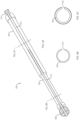
- Extension device 300 has a tubular inner member 302 including a lumen extending therethrough.
- the device 300 also includes a tubular outer member 304 having a lumen extending therethrough, which is configured to receive the inner member 302.
- the lumen of the outer member 304 may have a diameter that substantially matches the outer diameter of the inner member 302.
- the outer member 304 and inner member 302 are slidable relative to each other in a telescoping fashion to a desired position that corresponds to an adjustable length of the device 300.
- a locking assembly 306 (e.g., a screw or the like) is configured to fix a relative position of the outer 304 member and the inner member 302 with respect to each other at the desired position.
- the locking assembly 306 locks the outer member 304 with respect to the inner member 302 at the desired position by engaging the inner member 302.
- the locking assembly 306 shown in FIGS. 2-3 includes a knobbed screw that is disposed through an aperture of the outer member 304. A user may tighten the knobbed screw such that it engages and locks the inner member 302 with respect to the outer member 304.
- a proximal connector 310 (e.g., a luer-lock connector) at a proximal end of the outer member 304 is configured to connect to a distal end of a first medical device (e.g., a stent delivery device).
- a distal connector 308 (e.g., a female luer-lock connector) at a distal end of the inner member 302 is configured to connect to a proximal end of a second medical device (e.g., an endoscope).
- the locking assembly includes a protrusion 406 (e.g., a compressible button, a detent, or the like) on the inner member 402 that corresponds to preset apertures 412 in the outer member 404.
- the protrusion 406 can be compressed radially such that it completely enters and clears the inner surface of the lumen of the outer member 404, disengaging the inner member 402 from the apertures 412 of the outer member 404. This allows the inner member 402 and the protrusion 406 to slide with respect to the outer member 404, resulting in an adjustment of the overall length of the device 400.
- the locking assembly 406 may include a plurality of preset apertures 412 that correspond to a plurality of desired positions.
- the numerous positions of the locking assembly 406 may define predetermined adjustable lengths of the device 400.
- the apertures 412 and desired positions may correspond to known lengths required for use with an assortment of auxiliary devices such as endoscopes having different lengths of working channels.
- Each aperture 412 may correspond to a type of auxiliary device.
- the protrusion 406 may engage the aperture 412 corresponding to the auxiliary device being used to achieve the appropriate adjustable length of the device 400.
- An appropriate adjustable length of the device 400 may be such that a shaft extends through the device 400 with only a predetermined length of the shaft extending from the distal end of the auxiliary device. For example, FIG.
- the example of three fixed positions correspond to three predetermined adjustable lengths of the extension device that will shorten the effective length of the shaft by the amount of the adjustable length of the extension device.
- Visual indicators such as markings, may be on the inner and/or outer member that correspond to the desired positions.
- one or both of the inner and outer members may include fasteners that may have a first element on the inner member and a second element on the outer member configured to mate with each other.
- FIGS. 5A through 5F an embodiment of a device for extending a working channel according to the present disclosure is illustrated, which includes a channel 514 extending along an inner member 502, along a distal connector 508, and through to a lumen of the inner member 502.
- a channel 516 extends along the outer member 504, along the proximal connector 510, and through to the lumen of the outer member 504.
- the channels 514 and 516 of the inner member 502 and outer member 504 are configured to align with each other.
- the device 500 may be placed and removed from about a shaft of a medical device extending through the lumens of the inner member 502 and outer member 504 of the extension, including without having to proximally withdraw the shaft medical device from the extension device.
- One or both of the outer member 504 and the inner member 502 are rotatable with respect to each other.
- the device may be transitioned between an open configuration (e.g., as illustrated in FIGS. 5A-5C ) with the channel 514 and channel 516 substantially aligned, and a closed configuration (e.g., as illustrated in FIGS. 5D-5F ) with the channel 514 and channel 516 not substantially aligned.
- the device 500 When the device 500 is in the closed position with a shaft extending through the inner member 502 and the outer member 504, the device 500 and shaft are secure such that they cannot be separated from each other, other than to remove the shaft proximally through the inner member 502 and outer member 504.
- the device 500 When the device 500 is in the open position with the shaft disposed through the inner member 502 and the outer member 504, the device 500 may be removed from about the shaft in a substantially radial direction with respect to a longitudinal axis extending along the length of the channels 514 and 516.
- the one or more channels 514 and/or 516 extending along the distal connector 508 and/or the proximal connector 510 may instead be perforated material, weakened material, and/or thinner material than the remainder of the connector 508 and/or 510.
- the connector 508 and/or 510 may be made entirely of a material that is destructible by deliberate force of the user pulling or stripping the extension device 500 off of the shaft. Such embodiments may allow for the device 500 to be removed from an endoscope, and/or a shaft of a medical device without removing other parts of the system first. Such embodiments may also allow for the device 500 to be removed more rapidly compared to removing other auxiliary devices or other medical devices of the system before removing the extension device 500.
- the inner member and outer member may comprise various polymer and/or metallic materials.
- Materials may include stainless steel, aluminum, polytetrafluoroethylene (PTFE), ethylene tetrafluoroethylene (ETFE), fluorinated ethylene propylene (FEP), polyoxymethylene (POM, for example, DELRIN ® available from DuPont), polyether block ester, polyurethane (for example, Polyurethane 85A), polypropylene (PP), polyvinylchloride (PVC), polyether-ester (for example, ARNITEL ® available from DSM Engineering Plastics), ether or ester based copolymers (for example, butylene/poly(alkylene ether) phthalate and/or other polyester elastomers such as HYTREL ® available from DuPont), polyamide (for example, DURETHAN ® available from Bayer or CRISTAMID ® available from Elf Atochem), elastomeric
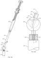
- FIGS. 6A and 6B an embodiment of a device for extending a working channel according to the present disclosure is illustrated, which includes a pivotable joint 620 disposed at a distal portion of an inner member 602 of the device 600.
- the device 600 extends the working channel of an endoscope 630 to be compatible with the shaft of the medical device 640, such that the shaft may extend a predetermined distance beyond the distal end of the endoscope.
- the pivotal joint 620 is proximal to a distal connector 608 that connects the device 600 to the endoscope 630.
- the joint 620 has a first longitudinal axis 627 that is alignable with a longitudinal axis of the endoscope 630 and a portion of the inner member 602 distal to the pivotal joint.
- the joint 620 also has a second longitudinal axis 621 that is alignable with a longitudinal axis of a remaining portion of the inner member 602.
- the joint 620 comprises a spherical body 622 at a distal portion of the inner member 602 that is proximal to the distal connector 608.
- the spherical body 620 has a lumen 624 therethrough that is in fluid communication with the lumen of the inner member 602.
- the joint 620 also includes a cupped body 626 at the distal portion of the inner member 602 that is proximal to the distal connector 608.
- the cupped body 626 is disposed about the spherical body 620.
- the cupped body 626 has a lumen 628 therethrough that is in fluid communication with the lumen 624 of the spherical body 622.
- the spherical body 620 is pivotable within the cupped body 626 while maintaining the lumens of the inner member 602, spherical body 622, and cupped body 626 in fluid communication.
- a shaft 642 of the medical device 640 is extendable through the lumens 624 and 628 of the joint 620.
- the joint 620 may pivot such that the first longitudinal axis 627 is at an angle of about 90 degrees to about 180 degrees from the second axis 621.
- a user may benefit from the pivotable joint 620 because it may allow for the medical device 640 and the device 600 to freely move angularly with respect to the cupped body 626 and the endoscope 630.
- the second axis 621 has freedom to move 360 degrees in any plane from 90 degrees (perpendicular to the first axis 627) to 180 degrees (parallel to the first axis 627). This may ergonomically assist the user during a procedure. There may be more freedom and comfort for the user operating the medical device 640 and endoscope 630 than that of other embodiments where the medical device, extension device, and endoscope are locked together in one position that cannot be pivoted with respect to each other.
- the proximal and/or distal connector may be a male or female luer fitting.
- the one or more connectors may include a rotating luer nut and/or a winded luer fitting.
- the connectors may removably connect and tighten to a variety of endoscopes and medical devices.
- the locking assembly may comprise a quick release locking nut, a twist frictional fit lock, a slotted fit lock, a button fit lock, a detent lock, or the like.
- the extension device may be a tubular member of a length corresponding to an endoscope such that a shaft of a catheter extends distally from the endoscope a predetermined distance.
- the tubular member may have a proximal connector at a proximal end of the member that is configured to connect to a distal end of a medical device.
- the tubular member may have a distal connector at a distal end of the member that is configured to connect to a proximal end of an endoscope.
- a method of extending a length of a working channel may include inserting an endoscope having a working channel into a patient.
- a catheter may be inserted into the patient through the working channel.
- An extension device may have a lumen extending therethrough about a shaft of the catheter.
- the extension device may be attached to a proximal end of the working channel.
- the catheter may be attached to a proximal end of the extension device.
- the extension device may be adjusted to a desired position that corresponds to an adjustable length of the extension device.
- the extension device may be locked at the desired position.
- the extension device may be adjusted to a desired position such that a distal tip of the catheter extends at most about 8 cm from a distal end of the endoscope.
- a tip of the catheter may be visualized using the endoscope.
- the extension device may be removed from the endoscope and from about a shaft of the catheter while the catheter remains within the working channel of the endoscope.
- the placing step may include placing the extension device about the shaft after inserting a catheter into the patient.
- the placing step may include placing the extension device about the shaft prior to inserting a catheter into the patient.
- the desired position may include at least one pre-determined fixed position of a locking assembly of the extension device configured to fix the adjustable length.
- the desired position may include a plurality of predetermined fixed positions.
- a plurality of channels of the extension device may be aligned with each other, such that the extension device may be placed and removed from about the shaft of the catheter.
- the extension device may be transitioned between an open configuration with the channels substantially aligned, and a closed configuration with the channels not substantially aligned.
Landscapes
- Health & Medical Sciences (AREA)
- Life Sciences & Earth Sciences (AREA)
- Surgery (AREA)
- Engineering & Computer Science (AREA)
- General Health & Medical Sciences (AREA)
- Veterinary Medicine (AREA)
- Pathology (AREA)
- Public Health (AREA)
- Nuclear Medicine, Radiotherapy & Molecular Imaging (AREA)
- Animal Behavior & Ethology (AREA)
- Biomedical Technology (AREA)
- Heart & Thoracic Surgery (AREA)
- Medical Informatics (AREA)
- Molecular Biology (AREA)
- Biophysics (AREA)
- Physics & Mathematics (AREA)
- Radiology & Medical Imaging (AREA)
- Optics & Photonics (AREA)
- Mechanical Engineering (AREA)
- Endoscopes (AREA)
- Media Introduction/Drainage Providing Device (AREA)
- Surgical Instruments (AREA)
- Prostheses (AREA)
Applications Claiming Priority (3)
| Application Number | Priority Date | Filing Date | Title |
|---|---|---|---|
| US201862655975P | 2018-04-11 | 2018-04-11 | |
| PCT/US2019/026506 WO2019199763A1 (en) | 2018-04-11 | 2019-04-09 | Devices and methods for extending a working channel |
| EP19719072.1A EP3773129B1 (de) | 2018-04-11 | 2019-04-09 | Vorrichtungen zur erweiterung eines arbeitskanals |
Related Parent Applications (1)
| Application Number | Title | Priority Date | Filing Date |
|---|---|---|---|
| EP19719072.1A Division EP3773129B1 (de) | 2018-04-11 | 2019-04-09 | Vorrichtungen zur erweiterung eines arbeitskanals |
Publications (2)
| Publication Number | Publication Date |
|---|---|
| EP4335352A2 true EP4335352A2 (de) | 2024-03-13 |
| EP4335352A3 EP4335352A3 (de) | 2024-05-15 |
Family
ID=66248804
Family Applications (2)
| Application Number | Title | Priority Date | Filing Date |
|---|---|---|---|
| EP19719072.1A Active EP3773129B1 (de) | 2018-04-11 | 2019-04-09 | Vorrichtungen zur erweiterung eines arbeitskanals |
| EP23205343.9A Pending EP4335352A3 (de) | 2018-04-11 | 2019-04-09 | Vorrichtungen und verfahren zur erweiterung eines arbeitskanals |
Family Applications Before (1)
| Application Number | Title | Priority Date | Filing Date |
|---|---|---|---|
| EP19719072.1A Active EP3773129B1 (de) | 2018-04-11 | 2019-04-09 | Vorrichtungen zur erweiterung eines arbeitskanals |
Country Status (7)
| Country | Link |
|---|---|
| US (3) | US20190313887A1 (de) |
| EP (2) | EP3773129B1 (de) |
| JP (5) | JP7175989B2 (de) |
| KR (3) | KR102617860B1 (de) |
| CN (2) | CN117224066A (de) |
| AU (1) | AU2019251104B2 (de) |
| WO (1) | WO2019199763A1 (de) |
Families Citing this family (6)
| Publication number | Priority date | Publication date | Assignee | Title |
|---|---|---|---|---|
| DE102018208537A1 (de) | 2018-05-30 | 2019-12-05 | Kardion Gmbh | Vorrichtung zum Anbinden eines Herzunterstützungssystems an eine Einführeinrichtung und Verfahren zum Herstellen einer Vorrichtung zum Anbinden eines Herzunterstützungssystems an eine Einführeinrichtung |
| DE102018208555A1 (de) | 2018-05-30 | 2019-12-05 | Kardion Gmbh | Vorrichtung zum Verankern eines Herzunterstützungssystems in einem Blutgefäß, Verfahren zum Betreiben und Herstellverfahren zum Herstellen einer Vorrichtung und Herzunterstützungssystem |
| DE102018211297A1 (de) | 2018-07-09 | 2020-01-09 | Kardion Gmbh | Herzunterstützungssystem und Verfahren zur Überwachung der Integrität einer Haltestruktur eines Herzunterstützungssystems |
| EP4217044A1 (de) * | 2020-09-25 | 2023-08-02 | Boston Scientific Scimed Inc. | Einführsystemadapter für ein endoskop |
| CN117222369A (zh) * | 2021-05-18 | 2023-12-12 | 恩多尚德股份有限公司 | 用于伸展内窥镜的装置、系统和方法 |
| US20240268649A1 (en) * | 2023-02-09 | 2024-08-15 | Cilag Gmbh International | Integrated cable connector for luminous efficiency |
Family Cites Families (45)
| Publication number | Priority date | Publication date | Assignee | Title |
|---|---|---|---|---|
| US4249541A (en) | 1979-04-26 | 1981-02-10 | David S. Pratt | Biopsy device |
| US4886049A (en) * | 1988-05-17 | 1989-12-12 | Darras Robert L | Medical instrument cover |
| US5350393A (en) * | 1992-01-06 | 1994-09-27 | Inbae Yoon | Safety trocar penetrating instrument |
| US5409498A (en) * | 1992-11-05 | 1995-04-25 | Ethicon, Inc. | Rotatable articulating endoscopic fastening instrument |
| DE19540731C2 (de) * | 1995-11-02 | 2001-03-01 | Wolf Gmbh Richard | Endoskopisches Instrument |
| US6520951B1 (en) * | 1996-09-13 | 2003-02-18 | Scimed Life Systems, Inc. | Rapid exchange catheter with detachable hood |
| DK200001852A (da) | 1999-12-14 | 2001-06-15 | Asahi Optical Co Ltd | Manipuleringssektion til et endoskopisk behandlingsinstrument |
| JP4716594B2 (ja) * | 2000-04-17 | 2011-07-06 | オリンパス株式会社 | 内視鏡 |
| US6585639B1 (en) | 2000-10-27 | 2003-07-01 | Pulmonx | Sheath and method for reconfiguring lung viewing scope |
| US7056293B2 (en) | 2001-12-24 | 2006-06-06 | Lifeline Biotechnologies, Inc | Apparatus and method of use for identifying and monitoring women at risk of developing ovarian surface epithelium derived carcinomas |
| DE60327625D1 (de) * | 2002-05-31 | 2009-06-25 | Vidacare Corp | Gerät für den zugang zu knochenmark |
| US20040260199A1 (en) | 2003-06-19 | 2004-12-23 | Wilson-Cook Medical, Inc. | Cytology collection device |
| US7585290B2 (en) * | 2004-01-20 | 2009-09-08 | Ethicon Endo-Surgery, Inc. | Medical device for providing access |
| US8425539B2 (en) | 2004-04-12 | 2013-04-23 | Xlumena, Inc. | Luminal structure anchoring devices and methods |
| US7670282B2 (en) | 2004-06-14 | 2010-03-02 | Pneumrx, Inc. | Lung access device |
| US8075476B2 (en) | 2004-07-27 | 2011-12-13 | Intuitive Surgical Operations, Inc. | Cannula system and method of use |
| US20060200041A1 (en) | 2005-03-04 | 2006-09-07 | Ethicon Endo-Surgery, Inc. | Biopsy device incorporating an adjustable probe sleeve |
| JP2006288755A (ja) | 2005-04-11 | 2006-10-26 | Olympus Medical Systems Corp | 医療処置装置 |
| US10010371B2 (en) * | 2005-05-31 | 2018-07-03 | Aprovix Ab | Sampling system |
| JP4560455B2 (ja) * | 2005-08-01 | 2010-10-13 | オリンパスメディカルシステムズ株式会社 | 内視鏡 |
| EP1759629B1 (de) * | 2005-08-31 | 2014-04-02 | Karl Storz GmbH & Co. KG | Endoskop mit variabler Blickrichtung |
| JP4749855B2 (ja) * | 2005-12-13 | 2011-08-17 | オリンパスメディカルシステムズ株式会社 | 内視鏡用処置具 |
| US20070167868A1 (en) | 2006-01-18 | 2007-07-19 | Lsi Solutions, Inc. | Ergonomic needle tissue harvesting instrument not requiring a stylet |
| US7927271B2 (en) * | 2006-05-17 | 2011-04-19 | C.R. Bard, Inc. | Endoscope tool coupling |
| US9125761B2 (en) * | 2007-01-25 | 2015-09-08 | Boston Scientific Scimed, Inc. | Endoscope with preloaded or preloadable stent |
| US8114057B2 (en) * | 2007-02-05 | 2012-02-14 | Boston Scientific Scimed, Inc. | Medical systems including a telescoping sleeve and related components and methods |
| US20080243162A1 (en) * | 2007-04-02 | 2008-10-02 | Norikiyo Shibata | Trocar |
| AU2009289450B2 (en) * | 2008-09-05 | 2015-05-07 | Carnegie Mellon University | Multi-linked endoscopic device with spherical distal assembly |
| US9332973B2 (en) | 2008-10-01 | 2016-05-10 | Covidien Lp | Needle biopsy device with exchangeable needle and integrated needle protection |
| US20100191050A1 (en) | 2009-01-23 | 2010-07-29 | Ethicon Endo-Surgery, Inc. | Variable length accessory for guiding a flexible endoscopic tool |
| US20100228090A1 (en) * | 2009-03-06 | 2010-09-09 | Ethicon Endo-Surgery, Inc. | Methods and devices for providing access into a body cavity |
| US20100292532A1 (en) * | 2009-05-14 | 2010-11-18 | Terumo Cardiovascular Systems Corporation | Endoscopic Vessel Dissector With Side Entry |
| EP2434961B1 (de) * | 2009-05-29 | 2015-01-14 | Xlumena, Inc. | Vorrichtung und verfahren zum einsetzen eines stents in benachbarten gewebeschichten |
| WO2011112509A1 (en) | 2010-03-09 | 2011-09-15 | Cardiac Pacemakers, Inc. | Implantable defibrillation output circuit |
| US9204869B2 (en) * | 2012-01-09 | 2015-12-08 | Covidien Lp | Articulation control mechanisms |
| WO2013173045A1 (en) * | 2012-05-17 | 2013-11-21 | Xlumena, Inc. | Methods and devices for access across adjacent tissue layers |
| JP2014132979A (ja) * | 2013-01-10 | 2014-07-24 | Advanced Healthcare Kk | トロカールおよび手術支援システム |
| WO2015076154A1 (ja) * | 2013-11-21 | 2015-05-28 | オリンパスメディカルシステムズ株式会社 | 内視鏡処置具 |
| KR101514836B1 (ko) * | 2013-12-04 | 2015-04-24 | 주식회사 반도레포츠 | 접철식 폴대 |
| JP6404584B2 (ja) * | 2014-03-26 | 2018-10-10 | オリンパス株式会社 | ステントデリバリーシステム |
| DE102014010398A1 (de) * | 2014-07-15 | 2016-01-21 | Olympus Winter & Ibe Gmbh | Kükenventil für den Flüssigkeitskanal eines chirugischen Instrumentes |
| WO2016143204A1 (ja) * | 2015-03-06 | 2016-09-15 | オリンパス株式会社 | 内視鏡用穿刺針及び生検システム |
| EP4591832A3 (de) * | 2015-05-14 | 2025-10-22 | Edwards Lifesciences Corporation | Herzklappenverschlussvorrichtungen und freisetzungsvorrichtungen dafür |
| EP3426189B1 (de) * | 2016-03-07 | 2024-01-17 | Boston Scientific Scimed, Inc. | Ösophagusstent mit einem ventilelement |
| US10660776B2 (en) * | 2016-04-11 | 2020-05-26 | Boston Scientific Scimed, Inc. | Stent delivery system with collapsible loading frame |
-
2019
- 2019-04-09 EP EP19719072.1A patent/EP3773129B1/de active Active
- 2019-04-09 KR KR1020227036732A patent/KR102617860B1/ko active Active
- 2019-04-09 AU AU2019251104A patent/AU2019251104B2/en not_active Ceased
- 2019-04-09 KR KR1020207032121A patent/KR102459345B1/ko active Active
- 2019-04-09 JP JP2020541869A patent/JP7175989B2/ja active Active
- 2019-04-09 CN CN202311221377.5A patent/CN117224066A/zh active Pending
- 2019-04-09 EP EP23205343.9A patent/EP4335352A3/de active Pending
- 2019-04-09 US US16/379,051 patent/US20190313887A1/en not_active Abandoned
- 2019-04-09 KR KR1020237044083A patent/KR102844050B1/ko active Active
- 2019-04-09 WO PCT/US2019/026506 patent/WO2019199763A1/en not_active Ceased
- 2019-04-09 CN CN201980025016.9A patent/CN111954484B/zh active Active
-
2022
- 2022-10-31 US US17/977,594 patent/US11980343B2/en active Active
- 2022-11-09 JP JP2022179435A patent/JP7513683B2/ja active Active
-
2024
- 2024-04-10 US US18/631,728 patent/US20240252022A1/en active Pending
- 2024-04-15 JP JP2024065373A patent/JP7691547B2/ja active Active
-
2025
- 2025-02-21 JP JP2025026307A patent/JP2025078647A/ja active Pending
- 2025-05-30 JP JP2025090769A patent/JP2025113500A/ja active Pending
Also Published As
| Publication number | Publication date |
|---|---|
| KR20240006073A (ko) | 2024-01-12 |
| JP2023017943A (ja) | 2023-02-07 |
| JP2024096879A (ja) | 2024-07-17 |
| US20240252022A1 (en) | 2024-08-01 |
| KR20200141072A (ko) | 2020-12-17 |
| KR20220148322A (ko) | 2022-11-04 |
| AU2019251104A1 (en) | 2020-07-30 |
| EP4335352A3 (de) | 2024-05-15 |
| EP3773129B1 (de) | 2023-10-25 |
| KR102617860B1 (ko) | 2023-12-27 |
| JP2021511887A (ja) | 2021-05-13 |
| CN111954484B (zh) | 2023-10-17 |
| KR102459345B1 (ko) | 2022-10-25 |
| US20230059972A1 (en) | 2023-02-23 |
| KR102844050B1 (ko) | 2025-08-11 |
| JP2025113500A (ja) | 2025-08-01 |
| US11980343B2 (en) | 2024-05-14 |
| JP2025078647A (ja) | 2025-05-20 |
| CN111954484A (zh) | 2020-11-17 |
| JP7175989B2 (ja) | 2022-11-21 |
| JP7513683B2 (ja) | 2024-07-09 |
| CN117224066A (zh) | 2023-12-15 |
| US20190313887A1 (en) | 2019-10-17 |
| AU2019251104B2 (en) | 2021-09-30 |
| EP3773129A1 (de) | 2021-02-17 |
| JP7691547B2 (ja) | 2025-06-11 |
| WO2019199763A1 (en) | 2019-10-17 |
Similar Documents
| Publication | Publication Date | Title |
|---|---|---|
| US11980343B2 (en) | Devices and methods for extending a working channel | |
| US20260083302A1 (en) | Devices with an adjustable effective working shaft length | |
| CN118265493A (zh) | 经由胆道进入装置的装置输送 |
Legal Events
| Date | Code | Title | Description |
|---|---|---|---|
| PUAI | Public reference made under article 153(3) epc to a published international application that has entered the european phase |
Free format text: ORIGINAL CODE: 0009012 |
|
| STAA | Information on the status of an ep patent application or granted ep patent |
Free format text: STATUS: REQUEST FOR EXAMINATION WAS MADE |
|
| 17P | Request for examination filed |
Effective date: 20231123 |
|
| AC | Divisional application: reference to earlier application |
Ref document number: 3773129 Country of ref document: EP Kind code of ref document: P |
|
| AK | Designated contracting states |
Kind code of ref document: A2 Designated state(s): AL AT BE BG CH CY CZ DE DK EE ES FI FR GB GR HR HU IE IS IT LI LT LU LV MC MK MT NL NO PL PT RO RS SE SI SK SM TR |
|
| REG | Reference to a national code |
Ref country code: DE Ref legal event code: R079 Free format text: PREVIOUS MAIN CLASS: A61B0001018000 Ipc: A61B0001000000 |
|
| PUAL | Search report despatched |
Free format text: ORIGINAL CODE: 0009013 |
|
| AK | Designated contracting states |
Kind code of ref document: A3 Designated state(s): AL AT BE BG CH CY CZ DE DK EE ES FI FR GB GR HR HU IE IS IT LI LT LU LV MC MK MT NL NO PL PT RO RS SE SI SK SM TR |
|
| RIC1 | Information provided on ipc code assigned before grant |
Ipc: A61B 1/018 20060101ALI20240408BHEP Ipc: A61B 1/00 20060101AFI20240408BHEP |
|
| GRAP | Despatch of communication of intention to grant a patent |
Free format text: ORIGINAL CODE: EPIDOSNIGR1 |
|
| STAA | Information on the status of an ep patent application or granted ep patent |
Free format text: STATUS: GRANT OF PATENT IS INTENDED |