EP4335355A1 - Appareil ophtalmique, procédé de commande d'appareil ophtalmique et programme - Google Patents
Appareil ophtalmique, procédé de commande d'appareil ophtalmique et programme Download PDFInfo
- Publication number
- EP4335355A1 EP4335355A1 EP23195856.2A EP23195856A EP4335355A1 EP 4335355 A1 EP4335355 A1 EP 4335355A1 EP 23195856 A EP23195856 A EP 23195856A EP 4335355 A1 EP4335355 A1 EP 4335355A1
- Authority
- EP
- European Patent Office
- Prior art keywords
- eye
- illumination
- optical system
- optical axis
- lens
- Prior art date
- Legal status (The legal status is an assumption and is not a legal conclusion. Google has not performed a legal analysis and makes no representation as to the accuracy of the status listed.)
- Pending
Links
- 238000000034 method Methods 0.000 title claims description 39
- 230000003287 optical effect Effects 0.000 claims abstract description 556
- 238000005286 illumination Methods 0.000 claims abstract description 414
- 238000003384 imaging method Methods 0.000 claims abstract description 76
- 230000001678 irradiating effect Effects 0.000 claims abstract description 18
- 230000007246 mechanism Effects 0.000 claims description 141
- 230000008859 change Effects 0.000 claims description 21
- 210000000695 crystalline len Anatomy 0.000 description 206
- 238000010586 diagram Methods 0.000 description 34
- 210000004087 cornea Anatomy 0.000 description 16
- 230000000694 effects Effects 0.000 description 14
- 238000004590 computer program Methods 0.000 description 6
- 238000012545 processing Methods 0.000 description 6
- 230000005540 biological transmission Effects 0.000 description 5
- 230000004907 flux Effects 0.000 description 5
- 238000012014 optical coherence tomography Methods 0.000 description 4
- 238000001356 surgical procedure Methods 0.000 description 4
- 206010040007 Sense of oppression Diseases 0.000 description 3
- 208000002177 Cataract Diseases 0.000 description 2
- 239000002775 capsule Substances 0.000 description 2
- 238000004891 communication Methods 0.000 description 2
- 238000001514 detection method Methods 0.000 description 2
- 210000004127 vitreous body Anatomy 0.000 description 2
- 206010027646 Miosis Diseases 0.000 description 1
- 230000001464 adherent effect Effects 0.000 description 1
- 230000004075 alteration Effects 0.000 description 1
- 230000004323 axial length Effects 0.000 description 1
- 210000003161 choroid Anatomy 0.000 description 1
- 210000004240 ciliary body Anatomy 0.000 description 1
- 239000003086 colorant Substances 0.000 description 1
- 230000003247 decreasing effect Effects 0.000 description 1
- 230000005284 excitation Effects 0.000 description 1
- 210000000744 eyelid Anatomy 0.000 description 1
- 239000011521 glass Substances 0.000 description 1
- 238000013532 laser treatment Methods 0.000 description 1
- 239000004973 liquid crystal related substance Substances 0.000 description 1
- 239000000463 material Substances 0.000 description 1
- 238000005259 measurement Methods 0.000 description 1
- 230000004048 modification Effects 0.000 description 1
- 238000012986 modification Methods 0.000 description 1
- 210000004279 orbit Anatomy 0.000 description 1
- 230000002093 peripheral effect Effects 0.000 description 1
- 210000001747 pupil Anatomy 0.000 description 1
- 230000010255 response to auditory stimulus Effects 0.000 description 1
- 210000001525 retina Anatomy 0.000 description 1
- 230000002207 retinal effect Effects 0.000 description 1
- 239000004065 semiconductor Substances 0.000 description 1
- 238000005728 strengthening Methods 0.000 description 1
- 238000006467 substitution reaction Methods 0.000 description 1
- 238000012360 testing method Methods 0.000 description 1
- 239000003190 viscoelastic substance Substances 0.000 description 1
Images









Classifications
-
- A—HUMAN NECESSITIES
- A61—MEDICAL OR VETERINARY SCIENCE; HYGIENE
- A61B—DIAGNOSIS; SURGERY; IDENTIFICATION
- A61B3/00—Apparatus for testing the eyes; Instruments for examining the eyes
- A61B3/10—Objective types, i.e. instruments for examining the eyes independent of the patients' perceptions or reactions
- A61B3/13—Ophthalmic microscopes
-
- A—HUMAN NECESSITIES
- A61—MEDICAL OR VETERINARY SCIENCE; HYGIENE
- A61B—DIAGNOSIS; SURGERY; IDENTIFICATION
- A61B3/00—Apparatus for testing the eyes; Instruments for examining the eyes
- A61B3/0008—Apparatus for testing the eyes; Instruments for examining the eyes provided with illuminating means
-
- A—HUMAN NECESSITIES
- A61—MEDICAL OR VETERINARY SCIENCE; HYGIENE
- A61B—DIAGNOSIS; SURGERY; IDENTIFICATION
- A61B3/00—Apparatus for testing the eyes; Instruments for examining the eyes
- A61B3/0016—Operational features thereof
-
- A—HUMAN NECESSITIES
- A61—MEDICAL OR VETERINARY SCIENCE; HYGIENE
- A61B—DIAGNOSIS; SURGERY; IDENTIFICATION
- A61B3/00—Apparatus for testing the eyes; Instruments for examining the eyes
- A61B3/0016—Operational features thereof
- A61B3/0041—Operational features thereof characterised by display arrangements
-
- A—HUMAN NECESSITIES
- A61—MEDICAL OR VETERINARY SCIENCE; HYGIENE
- A61B—DIAGNOSIS; SURGERY; IDENTIFICATION
- A61B3/00—Apparatus for testing the eyes; Instruments for examining the eyes
- A61B3/0016—Operational features thereof
- A61B3/0041—Operational features thereof characterised by display arrangements
- A61B3/005—Constructional features of the display
-
- A—HUMAN NECESSITIES
- A61—MEDICAL OR VETERINARY SCIENCE; HYGIENE
- A61B—DIAGNOSIS; SURGERY; IDENTIFICATION
- A61B3/00—Apparatus for testing the eyes; Instruments for examining the eyes
- A61B3/0075—Apparatus for testing the eyes; Instruments for examining the eyes provided with adjusting devices, e.g. operated by control lever
-
- A—HUMAN NECESSITIES
- A61—MEDICAL OR VETERINARY SCIENCE; HYGIENE
- A61B—DIAGNOSIS; SURGERY; IDENTIFICATION
- A61B3/00—Apparatus for testing the eyes; Instruments for examining the eyes
- A61B3/10—Objective types, i.e. instruments for examining the eyes independent of the patients' perceptions or reactions
- A61B3/12—Objective types, i.e. instruments for examining the eyes independent of the patients' perceptions or reactions for looking at the eye fundus, e.g. ophthalmoscopes
-
- A—HUMAN NECESSITIES
- A61—MEDICAL OR VETERINARY SCIENCE; HYGIENE
- A61B—DIAGNOSIS; SURGERY; IDENTIFICATION
- A61B3/00—Apparatus for testing the eyes; Instruments for examining the eyes
- A61B3/10—Objective types, i.e. instruments for examining the eyes independent of the patients' perceptions or reactions
- A61B3/13—Ophthalmic microscopes
- A61B3/132—Ophthalmic microscopes in binocular arrangement
-
- A—HUMAN NECESSITIES
- A61—MEDICAL OR VETERINARY SCIENCE; HYGIENE
- A61B—DIAGNOSIS; SURGERY; IDENTIFICATION
- A61B3/00—Apparatus for testing the eyes; Instruments for examining the eyes
- A61B3/10—Objective types, i.e. instruments for examining the eyes independent of the patients' perceptions or reactions
- A61B3/14—Arrangements specially adapted for eye photography
-
- G—PHYSICS
- G02—OPTICS
- G02B—OPTICAL ELEMENTS, SYSTEMS OR APPARATUS
- G02B21/00—Microscopes
- G02B21/0004—Microscopes specially adapted for specific applications
- G02B21/0012—Surgical microscopes
-
- G—PHYSICS
- G02—OPTICS
- G02B—OPTICAL ELEMENTS, SYSTEMS OR APPARATUS
- G02B21/00—Microscopes
- G02B21/06—Means for illuminating specimens
-
- G—PHYSICS
- G02—OPTICS
- G02B—OPTICAL ELEMENTS, SYSTEMS OR APPARATUS
- G02B21/00—Microscopes
- G02B21/06—Means for illuminating specimens
- G02B21/08—Condensers
- G02B21/082—Condensers for incident illumination only
-
- G—PHYSICS
- G02—OPTICS
- G02B—OPTICAL ELEMENTS, SYSTEMS OR APPARATUS
- G02B21/00—Microscopes
- G02B21/18—Arrangements with more than one light path, e.g. for comparing two specimens
- G02B21/20—Binocular arrangements
- G02B21/22—Stereoscopic arrangements
Definitions
- the disclosure relates to an ophthalmic apparatus, a method of controlling the ophthalmic apparatus, and a program.
- Types of ophthalmic apparatuses include ophthalmic imaging apparatuses for obtaining images of an eye to be examined, ophthalmic measuring apparatuses for measuring characteristics of an eye to be examined, and the like.
- Examples of the ophthalmic imaging apparatus include an optical coherence tomography (OCT) apparatus using OCT, a fundus camera, a scanning laser ophthalmoscope (SLO), a slit lamp, and the like.
- Examples of the ophthalmic measuring apparatus include an eye refraction test apparatus (refractometer, keratometer), a tonometer, a specular microscope, a wavefront analyzer, and the like.
- examples of the ophthalmic apparatus include an operating microscope, a laser photocoagulator, and the like.
- the operating microscopes are apparatuses for illuminating an eye to be operated as the eye to be examined with illumination light and observing an image formed by returning light of the illumination light from the eye to be operated using an observation optical system. Magnified images of the eye to be operated can be observed using a variable power lens system in the observation optical system.
- Such operating microscopes are used in ophthalmic surgery, such as a cataract surgery, a retinal and vitreous surgery.
- One aspect of the embodiments is an ophthalmic apparatus, including: an objective lens; a first illumination optical system arranged approximately coaxially with an optical axis of the objective lens and configured to be capable of irradiating first illumination light onto an eye to be examined through the objective lens; a second illumination optical system arranged so as to be eccentric to the optical axis of the objective lens and configured to be capable of irradiating second illumination light onto the eye to be examined through the objective lens; a left-eye observation optical system configured to be capable of guiding returning light from the eye to be examined, where the first illumination light or the second illumination light has entered through the objective lens, to a left-eye eyepiece or a left-eye imaging element; and a right-eye observation optical system configured to be capable of guiding returning light from the eye to be examined, where the first illumination light or the second illumination light has entered through the objective lens, to a right-eye eyepiece or a right-eye imaging element, wherein the second illumination optical system is capable of changing an incident angle of a principal ray of the
- Another aspect of the embodiments is a method of controlling an ophthalmic apparatus including: an objective lens; a first illumination optical system arranged approximately coaxially with an optical axis of the objective lens and configured to be capable of irradiating first illumination light onto an eye to be examined through the objective lens; a second illumination optical system arranged so as to be eccentric to the optical axis of the objective lens and configured to be capable of irradiating second illumination light onto the eye to be examined through the objective lens; a left-eye observation optical system configured to be capable of guiding returning light from the eye to be examined, where the first illumination light or the second illumination light has entered through the objective lens, to a left-eye eyepiece or a left-eye imaging element; a right-eye observation optical system configured to be capable of guiding returning light from the eye to be examined, where the first illumination light or the second illumination light has entered through the objective lens, to a right-eye eyepiece or a right-eye imaging element; and a controller configured to control at least the first illumination optical system and the second illumination optical
- the method of controlling an ophthalmic apparatus includes a first illumination step of irradiating the first illumination light onto the eye to be examined by controlling the first illumination optical system by the controller, and a second illumination step of irradiating the second illumination light, whose incident angle of a principal ray has been changed relative to the eye to be examined by controlling the second illumination optical system by the controller, onto the eye to be examined.
- Still another aspect of the embodiments is a program of causing a computer to execute each step of method of controlling the ophthalmic apparatus described above.
- a new technique for stereoscopically perceiving the eye to be examined appropriately depending on the observers can be provided.
- an operating microscope that enables binocular observation of the eye to be operated as the eye to be examined will be described as an ophthalmic apparatus for binocular observation of the eye to be examined.
- the following embodiments can be applied not only to operating microscopes but also to any ophthalmic apparatuses that allows binocular observation of the eye to be examined.
- a target site to be observed may be any site in an anterior segment or a posterior segment of the eye to be operated.
- the target site to be observed in the anterior segment include a cornea, a corner angle, a vitreous body, a crystalline lens, and a ciliary body.
- the target site to be observed in the posterior segment include a retina (fundus), a choroid, and a vitreous body.
- the target site to be observed may also be any peripheral site of the eye such as an eyelid and an eye socket.
- An operating microscope can be configured to allow observation of a fundus or an anterior segment of an eye to be operated by inserting a lens into or removing a lens from between the eye to be operated and an objective lens, for example.
- the operating microscope may have a function as another ophthalmic apparatus, in addition to a function as a microscope for magnified observation of the eye to be operated.
- the function as another ophthalmic apparatus include functions such as a function of performing OCT, a function of a laser treatment, a function of measuring an axial length, a function of measuring refractive power, a function of measuring a higher-order aberration.
- Another ophthalmic apparatus may have an arbitrary configuration capable of performing examination, measurement, or imaging of the eye to be operated using an optical method.
- FIG. 1 shows an example of a configuration of an ophthalmic system including an operating microscope according to a first embodiment.
- An ophthalmic system 1 includes an operation apparatus (operating device, control device) 2, a display apparatus 3, and an operating microscope 10.
- the operating microscope 10 includes at least one of the operation apparatus 2 and the display apparatus 3.
- the operation apparatus 2 includes an operation device or an input device.
- the operation apparatus 2 includes buttons and switches (e.g., operation handle, operation knob, foot switch, etc.) that can be operated with a part of body, such as a hand, a finger, an elbow, a foot, and operation devices (e.g., mouse, keyboard, etc.).
- the operation apparatus 2 may include any operation device or any input device, such as a trackball, a control panel, a switch, a button, a dial, etc.
- the operation apparatus 2 is a device capable of outputting an operation signal corresponding to the operation content of the operation in response to sound, such as voice, light, or gestures of the operator.
- the display apparatus 3 displays images of the eye to be operated acquired by the operating microscope 10.
- the display apparatus 3 is configured to include a display device such as a flat panel display such as an LCD (Liquid Crystal Display).
- the display apparatus 3 may include various types of display devices such as a touch panel.
- the display apparatus 3 is a display device capable of stereoscopic viewing.
- the operation apparatus 2 and the display apparatus 3 do not need to be configured to be separate devices.
- a device like a touch panel, which has an operation function integrated with a display function can be used.
- the operation apparatus 2 includes the touch panel and a computer program(s).
- the operation content to the operation apparatus 2 is input to a controller (not shown) as electrical signals.
- operations (manipulations) and inputs of information may be performed using a graphical user interface (GUI), which is displayed on the display apparatus 3, and the operation apparatus 2.
- GUI graphical user interface
- the functions of the operation apparatus 2 and the display apparatus 3 are realized by a touch screen.
- the operating microscope 10 is used for observing magnified images of the eye to be operated of a patient in a supine position.
- the magnified images can be observed by displaying captured images of the eye to be operated on the display apparatus 3.
- the magnified images can be observed by guiding returning light from the eye to be operated to an eyepiece (not shown).
- the operating microscope 10 includes a communication unit for sending and receiving electrical signals with the operation apparatus 2.
- the operating microscope 10 is controlled according to the operation content corresponding to the electrical signals (including electromagnetic wave) input from the operation apparatus 2 via a wired or wireless signal path.
- the operating microscope 10 includes a communication unit for sending and receiving electrical signals with the display apparatus 3.
- the operating microscope 10 displays images on a screen of the display apparatus 3 according to a display control content corresponding to the electrical signals output to the display apparatus 3 via a wired or wireless signal path.
- a direction of an optical axis of an objective lens is defined as a z-direction (vertical direction or perpendicular direction during operation), a horizontal direction orthogonal to the z-direction is defined as an x-direction (horizontal direction during operation), and a horizontal direction orthogonal to the both of the z-direction and the x-direction is defined as a y-direction.
- an observation optical system has an optical system for binocular observation
- the configuration according to the embodiments can also be applied to the configuration of the observation optical system having an optical system for monocular observation.
- FIG. 2 shows an example of a configuration of an optical system of the operating microscope 10 according to the first embodiment.
- FIG. 2 shows a schematic top view of the optical system from upper side and a schematic side view of the optical system from the side.
- the top view and the side view are illustrated in corresponding to each other.
- an illumination optical system 30, which is positioned above an objective lens 20, is omitted.
- the operating microscope 10 includes the objective lens 20, a dichroic mirror DM1, the illumination optical system 30, and an observation optical system 40.
- the observation optical system 40 includes a zoom expander 50 and an imaging camera 60.
- the illumination optical system 30 or the observation optical system 40 includes the dichroic mirror DM1.
- the objective lens 20 is positioned to face to the eye to be operated.
- An optical axis of objective lens 20 is assumed to extend in the z-direction. In other words, the direction from the cornea of the eye to be operated to the fundus is approximately parallel to the z-direction.
- the objective lens 20 includes two or more lenses including a lens positioned to face to the eye to be operated.
- the dichroic mirror DM1 couples an optical path of the illumination optical system 30 with an optical path of the observation optical system 40.
- the dichroic mirror DM1 is arranged between the illumination optical system 30 and the objective lens 20.
- the dichroic mirror DM1 transmits illumination light from the illumination optical system 30 to guide the illumination light to the objective lens 20, and reflects returning light of the illumination light from the eye to be operated traveling through the objective lens 20 to guide the returning light to the imaging camera 60 of the observation optical system 40.
- the dichroic mirror DM1 coaxially couples the optical path of the illumination optical system 30 with the optical path of the observation optical system 40.
- the dichroic mirror DM1 coaxially couples an optical path of a left-eye illumination optical system (first illumination optical system 31L) with an optical path of a left-eye observation optical system 40L, and coaxially couples an optical path of a right-eye illumination optical system (first illumination optical system 31R) with an optical path of a right-eye observation optical system 40R.
- the illumination optical system 30 is an optical system for illuminating the eye to be operated through the objective lens 20.
- the illumination optical system 30 can illuminate the eye to be operated with any of two or more illumination light having different color temperatures.
- the illumination optical system 30 Upon receiving instruction from a controller described below, illuminates the eye to be operated with illumination light having a designated color temperature.
- the illumination optical system 30 includes the first illumination optical systems 31L and 31R, and second illumination optical system 32.
- Each of optical axes OL and OR of the first illumination optical systems 31L and 31R is positioned so as to be approximately coaxial with the optical axis of the objective lens 20 (coaxial illumination). This allows to illuminate the fundus with so-called "0-degree illumination” and to acquire a transillumination image generated by diffuse reflection of the illumination light on the fundus. In this case, the binocular observation of the transillumination image of the eye to be operated becomes possible.
- An optical axis OS of the second illumination optical system 32 is positioned so as to be eccentric to the optical axis of the objective lens 20 (non-coaxial illumination).
- the second illumination optical system 32 is configured to be capable of changing an incident angle of a principal ray of the illumination light relative to the eye to be operated (specifically, target site to be observed such as the fundus). This allows to illuminate the fundus or the anterior segment with so-called "angled illumination (oblique illumination, diagonal illumination)", and to binocularly observe the eye to be operated (transillumination image) while avoiding the effects of ghosting based on reflections from the cornea and other parts of the eye.
- the fundus can be illuminated using at least one of the first illumination optical systems 31L and 31R, and the second illumination optical system 32 by operation of a user such as an operator (surgeon) to the operation apparatus 2.
- the fundus is illuminated using all of the first illumination optical systems 31L and 31R, and the second illumination optical system 32.
- the fundus is illuminated using the first illumination optical systems 31L and 31R alone (the second illumination optical system 32 is off).
- the fundus is illuminated using only the second illumination optical system 32 alone (both of the first illumination optical systems 31L and 31R are off).
- the fundus is illuminated using one of the first illumination optical systems 31L and 31R and the second illumination optical system 32 (another of the first illumination optical systems 31L and 31R is off).
- the first illumination optical system 31L includes a light source 31LA and a condenser lens 31LB.
- the light source 31LA for example, outputs illumination light having a wavelength in the visible region with a color temperature of 3000 K (Kelvin).
- the illumination light output from the light source 31LA passes through the condenser lens 31LB, is transmitted through the dichroic mirror DM1, passes through the objective lens 20, and enters the eye to be operated.
- the first illumination optical system 31R includes a light source 31RA and a condenser lens 31RB.
- the light source 31RA also outputs illumination light having a wavelength in the visible region with a color temperature of 3000 K, for example.
- the illumination light output from the light source 31RA passes through the condenser lens 31RB, is transmitted through the dichroic mirror DM1, passes through the objective lens 20, and enters the eye to be operated.
- the second illumination optical system 32 includes a light source unit 32A and a projector 32B.
- the light source unit 32A for example, outputs illumination light having a wavelength in the visible region with a color temperature of 4000 K to 6000 K.
- the illumination light output from the light source unit 32A passes through the projector 32B, passes through the objective lens 20 without passing through the dichroic mirror DM1, and enters the eye to be operated.
- the color temperature of the illumination light from the first illumination optical systems 31L and 31R is lower than the color temperature of the illumination light from the second illumination optical system 32. This allows to observe the eye to be operated in warm colors using the first illumination optical systems 31L and 31R, and to grasp the morphology of the eye to be operated in detail.
- each of the optical axis OL of the first illumination optical system 31L and the optical axis OR of the first illumination optical system 31R is movable relative to the optical axis of the objective lens 20 in a direction intersecting the optical axis of the objective lens 20 (at least one of the x-direction and the y-direction).
- each of the optical axis OL of the first illumination optical system 31L and the optical axis OR of the first illumination optical system 31R can be moved independently.
- the optical axis OL of the first illumination optical system 31L and the optical axis OR of the first illumination optical system 31R can be moved integrally.
- the operating microscope 10 includes a movement mechanism (31d) that independently or integrally moves the first illumination optical systems 31L and 31R, and moves the first illumination optical systems 31L and 31R independently or integrally in a direction that intersects the optical axis of the objective lens 20 using the movement mechanism.
- the movement mechanism moves the optical axes OL and OR under the control from the controller described below.
- respective orientations (inclination of the optical axis) of the optical axis OL of the first illumination optical system 31L and the optical axis OR of the first illumination optical system 31R can be changed.
- each of the orientation of the optical axis OL of the first illumination optical system 31L and the orientation of the optical axis OR of the first illumination optical system 31R can be changed independently.
- the orientations of the optical axis OL of the first illumination optical system 31L and the optical axis OR of the first illumination optical system 31R can be changed integrally.
- FIG. 3 shows a schematic diagram from the side view of the first illumination optical system 31R according to the first embodiment.
- the first illumination optical system 31R is illustrated.
- like reference numerals designate like parts as in FIG. 2 , and the redundant explanation may be omitted as appropriate.
- the operating microscope 10 includes a movement mechanism (not shown, movement mechanism 31d) that tilts the optical axes OL and OR of the first illumination optical systems 31L and 31R independently or integrally.
- a movement mechanism (not shown, movement mechanism 31d) that tilts the optical axes OL and OR of the first illumination optical systems 31L and 31R independently or integrally.
- the movement mechanism integrally tilts the light source 31LA and the condenser lens 31LB.
- the movement mechanism integrally tilts the light source 31RA and the condenser lens 31RB. This allows to adjust the visibility of the eye to be operated. For example, the ghost based on reflections from the cornea, etc.
- the movement mechanism (31d) tilts each of the optical axis OL of the first illumination optical system 31L and the optical axis OR of the first illumination optical system 31R under the control from the controller described below.
- the second illumination optical system 32 can change the incident angle of the principal ray of the illumination light relative to the fundus.
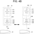
- FIG. 4A and FIG. 4B show schematic diagrams from the side view of the second illumination optical system 32 according to the first embodiment.
- like parts are designated by like reference numerals as in FIG. 2 and repetitious description of such parts may not be provided.
- the second illumination optical system 32 includes the light source unit 32A and the projector 32B.
- the light source unit 32A includes a light source 321, a collective lens 322, and a field diaphragm 323.
- the projector 32B includes a window lens 324, an aperture diaphragm 325, and a condenser lens 326.
- the light source unit 32A is configured to be capable of integrally tilting the light source 321, the collective lens 322, and the field diaphragm 323 relative to the projector 32B using the tilt mechanism.
- the tilt mechanism (32d1) changes the incident angle of the principal ray of the illumination light to the fundus, by changing an intersection angle (tilt angle, crossing angle) between an illumination optical axis of the illumination light output from the light source unit 32A and an optical axis of the projector 32B (lens optical axis of the condenser lens 326).
- the tilt mechanism tilts the light source unit 32A to the projector 32B in a direction of an arrow from a reference state (state before tilting the light source unit 32A).
- a reference state state before tilting the light source unit 32A.
- the tilt mechanism can change the intersection angle in a predetermined one-dimensional or two-dimensional direction.
- the tilt mechanism tilts the illumination optical axis of the illumination light relative to the lens optical axis, that has been fixed, of the condenser lens 326 along a circumference (in a circular direction) centered on the illumination optical axis (lens optical axis of the condenser lens 326) in the reference state.
- the tilt mechanism changes the intersection angle in stages or continuously.
- FIG. 5 schematically shows an illumination principal ray of the illumination light from the second illumination optical system 32.
- FIG. 5 represents a schematic diagram of the second illumination optical system 32 from the side view, as in FIG. 4A or FIG. 4B .
- like reference numerals designate like parts as in FIG. 4A or FIG. 4B . The same description may not be repeated.
- the intersection angle of the illumination optical axis relative to the lens optical axis is changed by tilting the illumination optical axis of the illumination light relative to the lens optical axis, that has been fixed, of the condenser lens 326 of the projector 32B.
- the orientation of the principal ray of the illumination light relative to the lens optical axis of the objective lens 20 is changed, and the incident angle of the principal ray PR of the illumination light relative to the fundus of the eye to be operated can be changed.
- the light quantity distribution of the illumination light on the fundus is changed as the irradiated range is changed, and other light fluxes of illumination light that eliminate shadows formed by some light fluxes of illumination light are reduced, and good shadow contrast can be achieved.
- the tilt angle of the light source unit 32A relative to the projector 32B can be changed by operating the operation apparatus 2 with the foot or other means while the operator is observing the fundus.
- the intersection angle of the illumination optical axis relative to the lens optical axis is changed by tilting the lens optical axis of the condenser lens 326 of the projector 32B relative to the illumination optical axis, that has been fixed, of the illumination light.
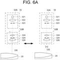
- FIG. 6A and FIG. 6B show schematic diagrams from the side view of the second illumination optical system 32 according to the first embodiment.
- like parts are designated by like reference numerals as in FIG. 4A and FIG. 4B and repetitious description of such parts may not be provided.
- the projector 32B is configured to be capable of integrally tilting the window lens 324, the aperture diaphragm 325, and the condenser lens 326 relative to the light source unit 32A.
- the tilt mechanism tilts the projector 32B relative to the light source unit 32A in a direction of an arrow from a reference state (state before tilting the projector 32B).
- the intersection angle of the lens optical axis of the condenser lens 326 relative to the illumination optical axis, that has been fixed, of the light source 321 of the light source unit 32A is changed.
- the tilt mechanism can change the intersection angle in a predetermined one-dimensional or two-dimensional direction.
- the tilt mechanism tilts the lens optical axis of the condenser lens 326 relative to the illumination optical axis, that has been fixed, of the light source 321 along a circumference (in a circular direction) centered on the lens optical axis (illumination optical axis) in the reference state.
- the tilt mechanism changes the intersection angle in stages or continuously.
- the optical axis OS of the second illumination optical system 32 is movable relative to the optical axis of the objective lens 20 in the direction that intersects the optical axis of the objective lens 20 (at least one of the x-direction and the y-direction).
- the operating microscope 10 includes a movement mechanism (shift mechanism) (not shown, movement mechanism 32d2) that moves the second illumination optical system 32.
- the movement mechanism moves the second illumination optical system 32 in a direction intersecting the optical axis of the objective lens 20.
- the movement mechanism integrally moves the light source unit 32A and the projector 32B in the direction that intersects the optical axis of the objective lens 20. This allows to adjust the visibility of the irregularities on a predetermined site of the eye to be operated. For example, the eye to be operated can be observed with a stereoscopic effect according to the preference of the operator or other person.
- the movement mechanism (32d2) moves the second illumination optical system 32 under the control from the controller described below.
- the operating microscope 10 includes a movement mechanism (not shown, movement mechanism 32d2) that moves an optical element (the light source unit 32A or the projector 32B described below) constituting the second illumination optical system 32.
- the movement mechanism changes a relative position of the projector 32B relative to the light source unit 32A (relative position in the direction intersecting the optical axis of the second illumination optical system 32).
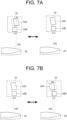
- FIG. 7A and FIG. 7B show schematic diagrams from the side view of the second illumination optical system 32 according to the first embodiment.
- like parts are designated by like reference numerals as in FIG. 2 and repetitious description of such parts may not be provided.
- the movement mechanism (32d2) changes the relative position of the light source unit 32A relative to the projector 32B by moving the light source unit 32A in a direction orthogonal to the optical axis of the second illumination optical system 32.
- the movement mechanism moves the light source unit 32A relative to the projector 32B in a direction of an arrow from the reference state (state before shifting the optical axis OS) in a state where the illumination optical axis is tilted relative to the lens optical axis of the condenser lens 326.
- the position of the optical axis OS is changed.
- an irradiated position of the illumination light from the light source unit 32A is changed on a lens surface of the condenser lens 326 and a lens surface of the objective lens 20, and an irradiated angle of the illumination light on the eye to be operated can be changed.
- FIG. 8A and FIG. 8B show schematic diagrams from the side view of the second illumination optical system 32 according to the first embodiment.
- like parts are designated by like reference numerals as in FIG. 2 and repetitious description of such parts may not be provided.
- the movement mechanism (32d2) changes the relative position of the projector 32B relative to the light source unit 32A by moving the projector 32B in a direction orthogonal to the optical axis of the second illumination optical system 32.
- the movement mechanism moves the projector 32B relative to the light source unit 32A in a direction of an arrow from the reference state.
- the position of the optical axis OS is changed.
- an irradiated position of the illumination light from the light source unit 32A is changed on a lens surface of the condenser lens 326 and a lens surface of the objective lens 20, and an irradiated angle of the illumination light on the eye to be operated can be changed.
- the controller described below can set the light source unit 32A and the projector 32B to the reference state shown in FIG. 4A , FIG. 4B , FIG. 6A , FIG. 6B , FIG. 7A, FIG. 7B , FIG. 8A, or FIG. 8B by controlling the movement mechanism (32d2).
- the illumination optical system 30 is positioned in the transmission direction of the dichroic mirror DM1 directly above the objective lens 20, and the observation optical system 40 is positioned in the reflection direction of the dichroic mirror DM1.
- the observation optical system 40 can be arranged so that the angle between the optical axis of the observation optical system 40 and a plane (xy-plane) orthogonal to the optical axis of the objective lens 20 is equal to or less than ⁇ 20 degrees.
- the observation optical system 40 which generally has a longer optical path length than the illumination optical system 30, is positioned so that the optical path length becomes longer in the direction approximately parallel to the xy-plane.
- the observation optical system 40 without the observation optical system 40 being placed in front of the operator, the operator can effortlessly view the screen of the display apparatus 3 in the front of the operator (or the situation in front of the operator).
- the housing placed in front of the operator no longer gives a feeling of oppression to the operator, and the burden on the operator is reduced.
- orientations of the optical axes of the first illumination optical systems 31L and 31R are configured to be changeable. Thereby, the visibility of the eye to be operated can be adjusted. For example, the ghost based on reflections from the cornea, etc. can be reduced, and the state of irregularities can be observed in detail.
- the incident angle of the principal ray of the illumination light from the second illumination optical system 32 to the eye to be operated is configured to be changeable, the contrast of the shadow at the target site to be observed of the eye to be operated can be adjusted. Thereby, the state of irregularities can be observed in detail with good contrast in the shadows for the operator or other persons.
- the second illumination optical system 32 is configured to be movable in the direction intersecting the optical axis of the objective lens 20, the visibility of the irregularities at a predetermined site on the eye to be operated can be adjusted.
- the eye to be operated can be observed with a stereoscopic effect according to the preference of the operator or other person.
- the observation optical system 40 is an optical system for observing an image formed by the returning light from the eye to be operated illuminated by the illumination light through the objective lens 20.
- the returning light from the eye to be operated is scattered light (reflected light) of the illumination light incident on the eye to be operated.
- the returning light from the eye to be operated includes scattered light (reflected light) of the illumination light incident on the eye to be operated and fluorescence and its scattered light using the illumination light incident on the eye to be operated as excitation light.
- the observation optical system 40 images the returning light on an imaging surface of an imaging element of the imaging camera 60.
- the observation optical system 40 includes a left-eye observation optical system 40L and a right-eye observation optical system 40R.
- the configuration of the left-eye observation optical system 40L is the same as the configuration of the right-eye observation optical system 40R.
- the left-eye observation optical system 40L and the right-eye observation optical system 40R are configured to allow the optical arrangements to be changed independently on the left and right sides.
- the zoom expander 50 includes a left-eye zoom expander 50L and a right-eye zoom expander 50R.
- the configuration of the left-eye zoom expander 50L is the same as the configuration of the right-eye zoom expander 50R.
- the left-eye zoom expander 50L and the right-eye zoom expander 50R are configured to allow the optical arrangements to be changed independently on the left and right sides.
- the left-eye zoom expander 50L includes a plurality of zoom lenses 51L, 52 L, and 53L. Each of the plurality of zoom lenses 51L, 52L, and 53L can be moved in the optical axis direction using a variable power mechanism (not shown).
- the right-eye zoom expander 50R includes a plurality of zoom lenses 51R, 52 R, and 53R. Each of the plurality of zoom lenses 51R, 52R, and 53R can be moved in the optical axis direction using a variable power mechanism.
- variable power mechanism moves each zoom lens of the left-eye zoom expander 50L and the right-eye zoom expander 50R in the optical axis direction independently or integrally. Thereby, the magnification is changed when photographing the eye to be operated.
- the variable power mechanism is controlled under the control from the controller described below.
- the imaging camera 60 is an optical system for capturing an image formed by the returning light from the eye to be operated, the returning light having been guided through the observation optical system 40.
- the imaging camera 60 includes a left-eye imaging camera 60L and a right-eye imaging camera 60R.
- the configuration of the left-eye imaging camera 60L is the same as the configuration of the right-eye imaging camera 60R.
- the left-eye imaging camera 60L and the right-eye imaging camera 60R are configured to allow the optical arrangements to be changed independently on the left and right sides.
- the left-eye imaging camera 60L includes an imaging lens 61L and an imaging element 62L.
- the imaging lens 61L images the returning light having passed through the left-eye zoom expander 50L onto the imaging surface of the imaging element 62L.
- the imaging element 62L is a two-dimensional area sensor.
- the imaging element 62L receives control from the controller described below and outputs an electrical signal (detection signal) corresponding to the light receiving result.
- the right-eye imaging camera 60R includes an imaging lens 61R and an imaging element 62R.
- the imaging lens 61R images the returning light having passed through the right-eye zoom expander 50R onto the imaging surface of the imaging element 62R.
- the imaging element 62R is a two-dimensional area sensor. The imaging element 62R receives control from the controller described below and outputs an electrical signal corresponding to the light receiving result.
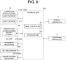
- FIG. 9 shows an example of a configuration of a control system of the operating microscope 10 according to the first embodiment.
- like reference numerals designate like parts as in FIG. 1 or FIG. 2 . The same description may not be repeated.
- the control system of the operating microscope 10 is configured with a controller 200 as a center. That is, the controller 200 executes control of each part of the operating microscope 10 (or ophthalmic system 1).
- the controller 200 executes various controls.
- the controller 200 includes a main controller 201 and a storage unit 202.
- the main controller 201 includes a processor and controls each part of the operating microscope 10 (or ophthalmic system 1).
- processor refers to a circuit such as, for example, a central processing unit (CPU), a graphics processing unit (GPU), an application specific integrated circuit (ASIC), and a programmable logic device (PLD).
- PLD programmable logic device
- Examples of PLD include a simple programmable logic device (SPLD), a complex programmable logic device (CPLD), and a field programmable gate array (FPGA).
- SPLD simple programmable logic device
- CPLD complex programmable logic device
- FPGA field programmable gate array
- the processor realizes, for example, the functions according to the embodiments by reading out a computer program stored in a storage circuit (storage unit 202) or a storage device and executing the computer program.
- the main controller 201 controls the light sources 31LA, 3 1RA, and 321 in the illumination optical system 30, the imaging elements 62L and 62R in the observation optical system 40, the movement mechanisms 31d and 32d2, the tilt mechanism 32d1, the variable power mechanisms 50Ld and 50Rd, the operation apparatus 2, the display apparatus 3, and the like.
- Examples of the control for the light source 31LA include turning the light source on and off, adjustment of the light quantity, adjustment of a diaphragm, and the like.
- Examples of the control for the light source 31RA include turning the light source on and off, adjustment of the light quantity, adjustment of a diaphragm, and the like.
- Examples of the control for the light source 321 include turning the light source on and off, adjustment of the light quantity, and the like.
- the main controller 201 can control the light source to output illumination light having a desired color temperature.
- the main controller 201 changes at least one of the light quantities of the light sources 31LA and 31RA and the light quantity of the light source 321 in accordance with the intersection angle (tilt angle) between the illumination optical axis of the illumination light output from the light source unit 32A and the lens optical axis of the condenser lens 326.
- the light quantity of the light source 321 is changed so that the light quantity of the light source 321 is gradually or continuously increased (or decreased) as the intersection angle increases.
- control information associated with the control contents for the light source 321 is stored in advance in the storage unit 202, corresponding to the intersection angles.
- the main controller 201 can change the light quantity of the light source 321 by referring to the control information.
- At least one of the light quantities of the light sources 31LA and 31RA, and the light quantity of the light source 321 is changed so that the light quantity of the light source 321 relative to the light quantity of light sources 31LA and 31RA becomes larger (or smaller) in stages or continuously as the intersection angle increases.
- control information associated with the control contents for the light sources 31LA and 31RA, and the control contents for the light source 321 is stored in advance in the storage unit 202, corresponding to the intersection angles.
- the main controller 201 can change at least one of the light quantities of the light sources 31LA and 31RA, and the light quantity of the light source 321 by referring to the control information.
- Examples of the control for the imaging element 62L include adjustment of exposure, adjustment of gain, adjustment of imaging rate, and the like.
- Examples of the control for the imaging element 62R include adjustment of exposure, adjustment of gain, adjustment of imaging rate, and the like.
- the main controller 201 can control the imaging elements 62L and 62R so that the shooting timings of the imaging elements 62L and 62R coincide or the difference in shooting timings of the imaging elements 62L and 62R is within a predetermined time. Further, the main controller 201 can perform readout control of the light receiving results in the imaging elements 62L and 62R.
- the movement mechanism 31d moves the orientations of the optical axes of the first illumination optical systems 31L and 31R independently or integrally. In case of changing the orientation of the optical axis of the first illumination optical system 31L, the movement mechanism 31d integrally tilts the light source 31LA and the condenser lens 31LB. In the same way, in case of changing the orientation of the optical axis of the first illumination optical system 31R, the movement mechanism 31d integrally tilts the light source 31RA and the condenser lens 31RB.
- the main controller 201 can change the orientations of the optical axes of the first illumination optical systems 31L and 31R independently or integrally, by controlling the movement mechanism 31d.
- the movement mechanism 32d2 independently or integrally moves the light source unit 32A in the direction approximately orthogonal to (intersecting, crossing) the optical axis of the objective lens 20.
- the main controller 201 can control the movement mechanism 32d2 to move the optical axis OS relative to the optical axis of the objective lens 20.
- the movement mechanism 32d2 changes the relative position of the projector 32B relative to the light source unit 32A (relative position in the direction intersecting the optical axis of the second illumination optical system 32). In some embodiments, the movement mechanism 32d2 changes the relative position of the light source unit 32A (illumination optical axis of the illumination light) relative to the projector 32B (condenser lens 326), by moving the light source unit 32A in the direction approximately orthogonal to the optical axis of the second illumination optical system 32. In some embodiments, the movement mechanism 32d2 changes the relative position of the projector 32B relative to the light source unit 32A, by moving the projector 32B in the direction approximately orthogonal to the optical axis of the second illumination optical system 32. The main controller 201 can control the movement mechanism 32d2 to change the relative position of the light source unit 32A and the projector 32B.
- the movement mechanisms 31d and 32d2 are configured to be cooperatively moved together.
- the main controller 201 can control one of the movement mechanisms 31d and 32d2 to move the other of the movement mechanisms 31d and 32d2.
- the main controller 201 can control the movement mechanism 32d2 to set the light source unit 32A and the projector 32B to the reference state shown in FIG. 4A , FIG. 4B , FIG. 6A , FIG. 6B , FIG. 7A, FIG. 7B , FIG. 8A, or FIG. 8B .
- the main controller 201 can control the movement mechanism 32d2 based on the operation content to the operation apparatus 2 to set the light source unit 32A and the projector 32B to the reference state shown in FIG. 4A , FIG. 4B , FIG. 6A , FIG. 6B , FIG. 7A, FIG. 7B , FIG. 8A, or FIG. 8B .
- This allows to always move the light source unit 32A or the projector 32B from the reference state, thereby eliminating deviations in the adjustment of the stereoscopic effect.
- the tilt mechanism 32d1 changes the intersection angle of the illumination optical axis of the illumination light from the light source unit 32A relative to the lens optical axis of the condenser lens 326 of the projector 32B.
- the main controller 201 controls the tilt mechanism 32d1 based on the operation content to the operation apparatus 2 to tilt the light source unit 32A relative to the fixed projector 32B.
- the main controller 201 controls the tilt mechanism 32d1 based on the operation content to the operation apparatus 2 to tilt the projector 32B relative to the fixed light source unit 32A. Thereby, the intersection angle of the illumination optical axis of the illumination light from the light source unit 32A relative to the lens optical axis of the condenser lens 326 of the projector 32B is changed.
- the movement mechanisms 31d and 32d2, and the tilt mechanism 32d1 are configured to be cooperatively moved together.
- the main controller 201 can control one of the movement mechanisms 31d and 32d2 and the tilt mechanism 32d1 to move the other two of the movement mechanisms 31d and 32d2 and the tilt mechanism 32d1.
- the variable power mechanism 50Ld moves at least one of the plurality of zoom lenses 51L to 53L in the left-eye zoom expander 50L in the optical axis direction.
- the main controller 201 can control the variable power mechanism 50Ld to move at least one of the plurality of zoom lenses 51L to 53L in the left-eye zoom expander 50L in the optical axis direction of the left-eye observation optical system 40L.
- the variable power mechanism 50Rd moves at least one of the plurality of zoom lenses 51R to 53R in the right-eye zoom expander 50R in the optical axis direction.
- the main controller 201 can control the variable power mechanism 50Rd to move at least one of the plurality of zoom lenses 51R to 53R in the right-eye zoom expander 50R in the optical axis direction of the right-eye observation optical system 40R.
- Examples of the control for the operation apparatus 2 include an operation permission control, an operation prohibition control, and a control for receiving the operation content to the operation apparatus 2.
- the main controller 201 can control each part of the operating microscope 10 (or ophthalmic system 1) according to the operation contents to the operation apparatus 2, by receiving electrical signals corresponding to the operation contents received from the operation apparatus 2.
- Examples of the control for the display apparatus 3 include a display control of various kinds of information.
- the main controller 201 as a display controller, can read out the light receiving results of the imaging elements 62L and 62R to form images of the eye to be operated, and can display the formed images of the eye to be operated on the screen of the display apparatus 3.
- the main controller 201 can read out the light receiving results of the imaging elements 62L and 62R to form an image for left eye (left eye image) and an image for right eye (right eye image) of the eye to be operated, and can display the formed image for left eye and the formed image for right eye of the eye to be operated on the screen of the display apparatus 3 in a manner that enables stereoscopic viewing.
- two disparity images one for right eye of an observer such as an operator and another for left eye of the observer, are formed from the image for left eye and the image for right eye of the eye to be operated, and the two disparity images formed are presented to the left eye and the right eye of the observer, respectively.
- the operator can visually recognize the eye to be operated stereoscopically, by observing the image of the eye to be operated with the naked eye or through polarizing glasses, using known methods.
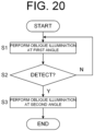
- the controller 200 controls the first illumination optical systems 31L and 31R (illumination optical system 30) to irradiate the eye to be operated with the illumination light (first illumination light) (first illumination step), and controls the second illumination optical system 32 to irradiate the eye to be operated with the illumination light (second illumination light) whose incident angle of the principal ray with respect to the eye to be operated has been changed (second illumination step).
- the controller 200 controls the tilt mechanism 32d1 to irradiate the illumination light (second illumination light), whose incident angle of the principal ray with respect to the eye to be operated has been changed, onto the eye to be operated.
- the illumination light output from the first illumination optical systems 31L and 31R is an example of the "first illumination light” according to the embodiments.
- the illumination light output from the second illumination optical system 32 is an example of the "second illumination light” according to the embodiments.
- the movement mechanism 32d2 is an example of the "shift mechanism” according to the embodiments.
- the controller 200 or the main controller 201 is an example of the “display controller” according to the embodiments.
- the display apparatus 3 is an example of the "display means" according to the embodiments.
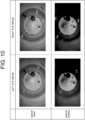
- FIG. 10 shows an example of a left eye image and a right eye image when a schematic eye is observed using the operating microscope 10 (ophthalmic system 1) according to the first embodiments.
- the left eye image is an image acquired using the left-eye observation optical system 40L.
- the right eye image is an image acquired using the right-eye observation optical system 40R.
- FIG. 10 represents the left eye image and the right eye image when the contrast of the shadows (shadow contrast) is weakened and the left eye image and the right eye image when the contrast of the shadows is strengthened, using the tilt mechanism 32d1.
- the schematic eye to be observed is marked in black on a portion corresponding to the cornea, is scratched on a portion corresponding to the anterior surface of lens (anterior capsule) and a portion corresponding to the posterior surface of lens (posterior capsule), and a hole (concave portion) is formed from the posterior surface of lens toward the anterior surface of lens in the schematic eye to be observed.
- a scratch L1 on the portion corresponding to the anterior surface of lens and a hole L2 formed from the posterior surface of lens toward the anterior surface of lens can be observed in the left eye image, for example.
- a scratch R1 on the portion corresponding to the anterior surface of lens, a hole R2 formed from the posterior surface of lens toward the anterior surface of lens, and a marking R3 marked on the portion corresponding to the cornea can be observed in the right eye image, for example.
- a scratch L3 on the portion corresponding to the anterior surface of lens and a scratch L4 on the portion corresponding to the posterior surface of lens can be observed in the left eye image, for example.
- a scratch R4 on the portion corresponding to the anterior surface of lens, and markings R5 and R6 on the portion corresponding to the cornea can be observed in the right eye image, for example.
- the scratch L3 and the marking R5 can be observed in more detail by strengthening the contrast of the shadows.
- the contrast of the shadows not only the detailed appearance of the fundus, but also the sites that can be observed in detail in the eye to be operated are changed, which not only increases the stereoscopic effect for the operator, but also assists in smooth operation.
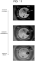
- FIG. 11 shows an example of the portion of the schematic eye that can be observed when the contrast of the shadows is changed using the tilt mechanism 32d1.
- FIG. 11 represents a right eye image when the schematic eye described above is observed with the contrast of the shadows weakened, a right eye image when the schematic eye described above is observed with the contrast of the shadows strengthened, and a right eye image when the schematic eye described above is observed with the contrast of the shadows set to an intermediate level of intensity.
- a scratch R11 on the portion corresponding to the anterior surface of lens, a marking R12 marked on the portion corresponding to the cornea, a hole R13 formed from the posterior surface of lens toward the anterior surface of lens, a marking R14 marked on the portion corresponding to the cornea, and a scratch R15 on the portion corresponding to the posterior surface of lens can be observed in the right eye image.
- a scratch R21 on the portion corresponding to the anterior surface of lens, a hole R22 formed from the posterior surface of lens toward the anterior surface of lens, a marking R23 marked on the portion corresponding to the cornea, and a scratch R24 on the portion corresponding to the posterior surface of lens can be observed in the right eye image.
- the sites that can be observed in detail in the eye to be operated are changed in accordance with the contrast of the shadows.
- the operator can adjust the contrast of the shadows using the tilt mechanism 32d1 so that the detailed observation of the site of interest is better.
- the focal positions of the left-eye observation optical system 40L and the right-eye observation optical system 40R are adjusted to be different from each other.
- focusing lenses can be provided for each of the left-eye observation optical system 40L and the right-eye observation optical system 40R, and the focal positions can be adjusted to be different from each other.
- the both focal positions can be adjusted to be different from each other.
- the both focal positions can be adjusted to be different from each other.
- the left-eye observation optical system 40L and the right-eye observation optical system 40R are optically arranged so that their focal positions differ by a predetermined distance.
- the left-eye observation optical system 40L is configured so that the focal point is located on the posterior surface of the lens
- the right-eye observation optical system 40R is configured so that the focal point is located on the cornea.
- the illumination optical system 30 is positioned in the transmission direction of the dichroic mirror DM1 directly above the objective lens 20, and the observation optical system 40 is positioned in the reflection direction of the dichroic mirror DM1. Since the optical path length of the observation optical system 40 is generally longer than that of the illumination optical system 30, the space available above the eye to be operated can be increased without the observation optical system 40 placed in front of the operator. This allows the operator to view the screen of the display apparatus 3 in front of the operator without difficulty. In addition, the housing placed in front of the operator no longer gives a feeling of oppression to the operator, and the burden on the operator is reduced.
- orientations of the optical axes of the first illumination optical systems 31L and 31R are configured to be changeable. Thereby, the visibility of the eye to be operated can be adjusted. For example, the ghost based on reflections from the cornea, etc. can be reduced, and the state of irregularities can be observed in detail.
- the intersection angle between the illumination optical axis of the illumination light from the light source unit 32A and the lens optical axis of the condenser lens 326 of the projector 32B is configured to be changeable. Thereby, the operator can adjust the contrast of the shadows for better detailed observation of the site of interest.
- the second illumination optical system 32 is configured to be movable in the direction intersecting the optical axis of the objective lens 20. Thereby, the visibility of irregularities on the predetermined site of the eye to be operated can be adjusted. For example, the eye to be operated can be observed with a contrast according to the preference of the operator or other person.
- the configuration of the operating microscope according to the embodiments is not limited to the configuration according to the first embodiment.
- a reflective mirror is placed above the objective lens 20, and the optical path of the illumination optical system 30 and the optical path of the observation optical system 40 are coupled and separated in the optical path deflected by the reflecting mirror.
- the configuration according to the second embodiment will be described mainly about the differences from the first embodiment.
- FIG. 12 shows an example of a configuration of an optical system of an operating microscope 10a according to the second embodiment.
- like reference numerals designate like parts as in FIG. 2 , and the redundant explanation may be omitted as appropriate.
- the operating microscope 10a according to the second embodiment can be applied instead of the operating microscope 10.
- the configuration of the operating microscope 10a according to the second embodiment differs from that of the operating microscope 10 according to the first embodiment in that a reflective mirror RM1 is provided instead of the dichroic mirror DM1 and a dichroic mirror DM2 is placed in the optical path deflected by the reflective mirror RM1.
- the dichroic mirror DM2 couples and separates the optical paths of the illumination optical system 30 and the observation optical system 40.
- the reflective mirror RM1 reflects the illumination light from the first illumination optical systems 31L and 31R toward the objective lens 20, and reflects the returning light from the eye to be operated toward the observation optical system 40.
- the dichroic mirror DM2 is placed in the optical path deflected by the reflective mirror RM1.
- the dichroic mirror DM2 is arranged between the reflective mirror RM1 and the zoom expander 50 in the observation optical system 40.
- the dichroic mirror DM2 couples the optical path of the illumination optical system 30 with the optical path of the observation optical system 40, in the same way as the dichroic mirror DM1.
- the dichroic mirror DM2 reflects the illumination light from the first illumination optical systems 31L and 31R toward the reflective mirror RM1 (objective lens 20), and transmits the returning light from the eye to be operated to guide the returning light to the zoom expander 50 (observation optical system 40).
- the dichroic mirror DM2 coaxially couples the optical path of the illumination optical system 30 with the optical path of the observation optical system 40.
- the dichroic mirror DM2 coaxially couples an optical path of the left-eye illumination optical system (first illumination optical system 31L) with an optical path of the left-eye observation optical system 40L, and coaxially couples an optical path of the right-eye illumination optical system (first illumination optical system 31R) with an optical path of the right-eye observation optical system 40R.
- the dichroic mirror DM2 coaxially couples the optical paths of the first illumination optical systems 31L and 31R in the reflection direction with the optical path of the left-eye observation optical system 40L and the optical path of the right-eye observation optical system 40R in the transmission direction.
- the dichroic mirror DM2 is configured to be capable of changing the reflection direction of the illumination light from the first illumination optical systems 31L and 31R using the movement mechanism (31d). This allows to adjust the visibility of the eye to be operated in the second embodiment, in the same way as in the first embodiment. For example, the ghost based on reflections from the cornea, etc. can be reduced, and the state of irregularities can be observed in detail.
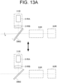
- FIG. 13A and FIG. 13B show schematic diagrams from the side view of the first illumination optical system 31R according to the second embodiment.
- the first illumination optical system 31R is illustrated.
- like parts are designated by like reference numerals as in FIG. 12 and repetitious description of such parts may not be provided.
- the operating microscope 10a includes a movement mechanism (not shown, movement mechanism 31d) that changes the orientation of the reflective surface of the dichroic mirror DM2.
- movement mechanism 31d changes the orientation of the reflective surface of the dichroic mirror DM2.
- the illumination light from the second illumination optical system 32 passes through the objective lens 20 to enter the eye to be operated without passing through the reflective mirror RM1.
- a control system of the operating microscope 10a according to the second embodiment is the same as the control system of the operating microscope 10 according to the first embodiment.
- the dichroic mirror DM2 is an example of the "beam splitter" according to the embodiments.
- the reflective mirror RM1 is positioned above the objective lens 20, and the coupled optical path between the optical path of the illumination optical system 30 and the optical path of the observation optical system 40 is guided to the objective lens 20.
- the illumination optical system 30 and the observation optical system 40 are positioned in the reflection direction of the reflective mirror RM1.
- the visibility of the eye to be operated can be adjusted, in the same way as in the first embodiment.
- the visibility of the irregularities on a predetermined site of the eye to be operated can be adjusted.
- the eye to be operated can be observed with a stereoscopic effect according to the preference of the operator or other person.
- the configuration of the operating microscope according to the embodiments is not limited to the configuration according to the embodiments described above.
- the eye to be operated is a microcoria eye (small pupil eye)
- it becomes difficult for the left and right illumination light to enter the eye through the pupil. Therefore, in the third embodiment, an optical axis width changing member for changing a width between the left and right optical axes is configured to be capable of being inserted into and removed from the coupled optical path between the optical path of the illumination optical system 30 and the optical path of the observation optical system 40.
- the configuration according to the third embodiment will be described mainly about the differences from the second embodiment.
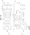
- FIG. 14 shows an example of a configuration of an optical system of the operating microscope 10b according to the third embodiment.
- like reference numerals designate like parts as in FIG. 12 , and the redundant explanation may be omitted as appropriate.
- the operating microscope 10b according to the third embodiment can be applied instead of the operating microscope 10.
- the configuration of the operating microscope 10b according to the third embodiment differs from that of the operating microscope 10a according to the second embodiment in that a stereo variator 70 as the optical axis width changing member is provided so as to be capable of being inserted into and removed from the optical path.
- the stereo variator 70 is, for example, as disclosed in Japanese Unexamined Patent Application Publication No. 2014-139002 , an optical element in which a first optical member and a second optical member, each having two parallel planes, are coupled, for example.
- the stereo variator 70 When the stereo variator 70 is placed in the optical path of the observation optical system 40, the two parallel planes of the first optical member are arranged to be inclined at a predetermined angle to the optical axis OL of the left-eye observation optical system 40L, and the two parallel planes of the second optical member are arranged to be inclined at a predetermined angle to the optical axis OR of the right-eye observation optical system 40R.
- the relative positions of the optical axes OL and OR are changed, and the width between the optical axes OL and OR can be narrowed for microcoria.
- the stereo variator 70 is inserted into and removed from the optical axis of the observation optical system 40, using the movement mechanism (70d) (not shown). In some embodiments, this movement mechanism is controlled under the control from a controller 200b described below.
- FIG. 15 shows an example of a configuration of a control system of the operating microscope 10b according to the third embodiment.
- like reference numerals designate like parts as in FIG. 9 , and the redundant explanation may be omitted as appropriate.
- the control system of the operating microscope 10b is configured with the controller 200b as a center. That is, the controller 200b executes control of each part of the operating microscope 10b (or ophthalmic system 1).
- the controller 200b executes various controls in the same manner as the controller 200.
- the controller 200b includes a main controller 201b and a storage unit 202b.
- control contents executed by controller 200b differ from those executed by controller 200 in that the control for moving the movement mechanism 70d is added.
- the movement mechanism 70d positions the stereo variator 70 on the optical axis (OL, OR) of the observation optical system 40, or moves the stereo variator 70 away from the optical axis of the observation optical system 40.
- the main controller 201b can control the movement mechanism 70d to insert the stereo variator 70 onto the optical axis of the observation optical system 40 or to remove the stereo variator 70 from the optical axis of the observation optical system 40.
- the main controller 201b controls the movement mechanism 70d based on the operation content to the operation apparatus 2.
- the main controller 201b controls the movement mechanism 70d based on an analysis result of an anterior segment image of the eye to be operated.
- the main controller 201b controls the movement mechanism 70d to position the stereo variator 70 on the optical axis of the observation optical system 40.
- the reflective mirror RM1 is positioned above the objective lens 20, and the coupled optical path between the optical path of the illumination optical system 30 and the optical path of the observation optical system 40 is guided to the objective lens 20.
- the illumination optical system 30 and the observation optical system 40 are positioned in the reflection direction of the reflective mirror RM1.
- the stereo variator 70 is inserted into or removed from the optical path of the observation optical system 40 arranged in the reflection direction of the reflective mirror RM1. Therefore, even when the eye to be operated is a microcoria eye, without the observation optical system 40, which has a long optical path length, being placed in front of the operator, the operator can view the screen of the display apparatus 3 in front of the operator without difficulty.
- the configuration of the operating microscope according to the embodiments is not limited to the configurations according to the first to the third embodiments.
- a fourth embodiment is configured to allow the operator or an assistant to observe the eye to be operated with the naked eye through the eyepiece (eyepiece lens).
- the configuration according to the fourth embodiment will be described mainly about the differences from the third embodiment. It should be noted that the fourth embodiment can be applied to the first embodiment or the second embodiment.
- FIG. 16 shows an example of a configuration of an optical system of the operating microscope 10c according to the fourth embodiment.
- parts similarly configured to those in FIG. 14 are denoted by the same reference numerals, and the description thereof is omitted unless it is necessary.
- the operating microscope 10c according to the fourth embodiment can be applied instead of the operating microscope 10.
- the configuration of the operating microscope 10c according to the fourth embodiment differs from that of the operating microscope 10b according to the third embodiment in that the observation optical system 40 includes an eyepiece system 63.
- the eyepiece system 63 includes a left-eye eyepiece system 63L and a right-eye eyepiece system 63R.
- the configuration of the left-eye eyepiece system 63L is the same as the configuration of the right-eye eyepiece system 63R.
- An optical path of the left-eye eyepiece system 63L is coaxially coupled with the optical path of the left-eye observation optical system 40L.
- An optical path of the right-eye eyepiece system 63R is coaxially coupled with the optical path of the right-eye observation optical system 40R.
- a beam splitter BSL is arranged between the left-eye zoom expander 50L and the left-eye imaging camera 60L.
- the left-eye eyepiece system 63L is arranged in the reflection direction of the beam splitter BSL.
- the left-eye imaging camera 60L is arranged in the transmission direction of the beam splitter BSL.
- the beam splitter BSL coaxially couples the optical path of the left-eye eyepiece system 63L with the optical path of the left-eye imaging camera 60L.
- the left-eye eyepiece system 63L includes an imaging lens 64L and an eyepiece 65L.
- the returning light, that has been guided through the optical path of the left-eye observation optical system 40L, from the eye to be operated is guided to the left-eye imaging camera 60L and the left-eye eyepiece system 63L by the beam splitter BSL.
- the returning light entering the left-eye eyepiece system 63L passes through the imaging lens 64L and is guided to the eyepiece 65L.
- a beam splitter BSR is arranged between the right-eye zoom expander 50R and the right-eye imaging camera 60R.
- the right-eye eyepiece system 63R is arranged in the reflection direction of the beam splitter BSR.
- the right-eye imaging camera 60R is arranged in the transmission direction of the beam splitter BSR.
- the beam splitter BSR coaxially couples the optical path of the right-eye eyepiece system 63R with the optical path of the right-eye imaging camera 60R.
- the right-eye eyepiece system 63R includes an imaging lens 64R and an eyepiece 65R.
- the returning light, that has been guided through the optical path of the right-eye observation optical system 40R, from the eye to be operated is guided to the right-eye imaging camera 60R and the right-eye eyepiece system 63R by the beam splitter BSR.
- the returning light entering the right-eye eyepiece system 63R passes through the imaging lens 64R and is guided to the eyepiece 65R.
- a control system of the operating microscope 10c according to the fourth embodiment is the same as the control system of the operating microscope 10b according to the third embodiment.
- the operator or the assistant can check the eye to be operated with the naked eye and can obtain the same effect as in the third embodiment.
- the configuration of the operating microscope according to the embodiments is not limited to the configurations according to the first to the fourth embodiments.
- the reflective mirror is arranged between the light source unit 32A and the projector 32B. And, by moving the reflective mirror, the intersection angle between the illumination optical axis of the illumination light from the light source unit 32A and the lens optical axis of the condenser lens 326 of the projector 32B is configured to be changeable.
- the configuration according to the fifth embodiment will be described mainly about the differences from the first embodiment. It should be noted that the fifth embodiment can be applied to the second to the fourth embodiments.
- FIG. 17 shows an example of the configuration of the second illumination optical system 32 according to the fifth embodiment.
- FIG. 17 represents a schematic diagram of the second illumination optical system 32 from the side view.
- like reference numerals designate like parts as in FIG. 4A or FIG. 4B . The same description may not be repeated.
- the second illumination optical system 32 includes the light source unit 32A, a reflective mirror RM, and the projector 32B.
- the light source unit 32A is arranged so that the illumination optical axis of the illumination light from light source 321 is approximately parallel to the optical axes of the left-eye observation optical system 40L and the right-eye observation optical system 40R (so as to be approximately orthogonal to the optical axes of the first illumination optical systems 31L and 31R).
- the projector 32B is arranged so that the lens optical axis of the condenser lens 326 is approximately orthogonal to the optical axes of the left-eye observation optical system 40L and the right-eye observation optical system 40R (so as to be approximately parallel to the optical axes of the first illumination optical systems 31L and 31R).
- the reflective mirror RM deflects the illumination light (illumination optical axis) from the light source 321 toward the projector 32B.
- the reflective mirror RM is configured to be movable in the direction of the illumination optical axis of the illumination light from the light source 321 (or in a direction that is approximately parallel to this direction).
- the operating microscope according to the fifth embodiment includes a movement mechanism (32d3) that moves the reflective mirror RM in the direction of the illumination optical axis of the illumination light from the light source 321 (or in a direction that is approximately parallel to this direction).
- the movement mechanism (32d3) moves the reflective mirror RM in the direction of the illumination optical axis of the illumination light from the light source 321 (or in a direction approximately parallel to this direction).
- the movement mechanism (32d3) moves the reflective mirror RM under the control from the controller 200c described below.
- the operating microscope according to the fifth embodiment can be applied instead of the operating microscope 10.
- FIG. 18 shows an example of a configuration of a control system of the operating microscope according to the fifth embodiment.
- like reference numerals designate like parts as in FIG. 9 , and the redundant explanation may be omitted as appropriate.
- control system of the operating microscope according to the fifth embodiment is configured with the controller 200c as a center. That is, the controller 200c executes control of each part of the operating microscope (or ophthalmic system 1) according to the fifth embodiment.
- the controller 200c executes various controls in the same manner as the controller 200.
- the controller 200c includes a main controller 201c and a storage unit 202c.
- control contents executed by controller 200c differ from those executed by controller 200 in that the control for moving the movement mechanism 32d3 is added.
- the main controller 201c controls the movement mechanism 32d3 to move the reflective mirror RM in the direction of the illumination optical axis of the illumination light from the light source 321 (or in a direction approximately parallel to this direction). In some embodiments, the main controller 201c controls the movement mechanism 32d3 based on the operation content to the operation apparatus 2.
- the intersection angle between the illumination optical axis of the illumination light from the light source unit 32A and the lens optical axis of the condenser lens 326 of the projector 32B is changed by moving the reflective mirror, which is arranged between the light source unit 32A and the projector 32B, in the second illumination optical system 32.
- the configuration and the operation of the operating microscope according to the embodiments are not limited to the configuration and the operation according to the first to the fifth embodiments.
- the shadow contrast may be changed based on the analysis, other detection results of the image of the eye to be operated acquired using the observation optical system 40, or the operation content of the operator or other person to the operation apparatus 2.
- the configuration according to the sixth embodiment will be described mainly about the differences from the first embodiment. It should be noted that the sixth embodiment can be applied to the second to the fifth embodiments.
- FIG. 19 shows an example of a configuration of a control system of the operating microscope according to the sixth embodiment.
- like reference numerals designate like parts as in FIG. 9 , and the redundant explanation may be omitted as appropriate.
- control system of the operating microscope according to the sixth embodiment is configured with the controller 200d as a center. That is, the controller 200d executes control of each part of the operating microscope (or ophthalmic system 1) according to the sixth embodiment.
- the configuration of the control system of the operating microscope according to the sixth embodiment differs from that of the operating microscope 10 according to the first embodiment in that a data processor 300 is added.
- the data processor 300 performs analysis processing on the image (left eye image, right eye image) of the eye to be operated acquired by the observation optical system 40 (left-eye observation optical system 40L, right-eye observation optical system 40R).
- the data processor 300 analyzes the image of the eye to be operated to detect a predetermined surgical appliance (e.g., an appliance (instrument) for Continuous Curvilinear Capsulorhexis (CCC)).
- a predetermined surgical appliance e.g., an appliance (instrument) for Continuous Curvilinear Capsulorhexis (CCC)
- the data processor 300 detects the surgical appliance by identifying a shape of a part of the surgical appliance, a shape of the whole of the surgical appliance, or the material of the surgical appliance in the image.
- the data processor 300 detects the surgical appliance by identifying an adjunct of the surgical appliance (which can be adherent of the appliance or applied to the appliance).
- the controller 200d executes various controls in the same manner as the controller 200.
- the controller 200d includes a main controller 201d and a storage unit 202d.
- control contents executed by controller 200d differ from those executed by controller 200 in that the control for the data processor 300 is added.
- the main controller 201d controls the tilt mechanism 32d1 or the movement mechanism 32d3 based on the analysis result of the image of the eye to be operated acquired by the data processor 300 to change the intersection angle of the lens optical axis of the condenser lens 326 of the projector 32B relative to the illumination optical axis of the illumination light from the light source 321.
- FIG. 20 is a flow diagram of an example of the operation of the operating microscope according to the sixth embodiment.
- the storage unit 202d stores computer program(s) for realizing the processing shown in FIG. 20 .
- the main controller 201d operates according to the computer programs, and thereby the main controller 201d performs the processing shown in FIG. 20 .
- the main controller 201d changes the intersection angle of the lens optical axis of the condenser lens 326 relative to the illumination optical axis of the illumination light so that the incident angle of the principal ray of the illumination light becomes a first angle to the eye to be operated, by controlling the tilt mechanism 32d1 or the movement mechanism 32d3.
- the fundus of the eye to be operated is illuminated with oblique illumination at the first angle.
- the first angle is an angle greater than 0 degrees.
- the main controller 201d controls the data processor 300 to detect the predetermined surgical appliance in the image of the eye to be operated.
- step S3 When the predetermined surgical appliance is detected in the image by the data processor 300 (S2: Y), the operation of the operating microscope proceeds to step S3.
- the predetermined surgical appliance is not detected in the image by the data processor 300 (S2: N), the operation of the operating microscope proceeds to step S1.
- the main controller 201d changes the intersection angle of the lens optical axis of the condenser lens 326 relative to the illumination optical axis of the illumination light so that the incident angle of the principal ray of the illumination light becomes a second angle to the eye to be operated, by controlling the tilt mechanism 32d1 or the movement mechanism 32d3.
- the fundus of the eye to be operated is illuminated with oblique illumination at the second angle.
- the second angle is 0 degrees.
- the optimal contrast of the shadows (shadow contrast) that allows for good observation depends on the phases of operation.
- the optimal contrast of the shadows that allows good observation also differs for the operators. For example, during the CCC in cataract surgery, it may be easier for some operators to operate without stereoscopic effect.
- the main controller 201d can control the tilt mechanism 32d1 or the movement mechanism 32d3 to change the intersection angle between the lens optical axis of the condenser lens 326 and the illumination optical axis of the illumination light from the light source unit 32A. Thereby, off-axis illumination can be performed so as to enhance the shadow contrast (step S1).
- the main controller 201d controls the tilt mechanism 32d1 or the movement mechanism 32d3 to set the light source unit 32A and the projector 32B to the reference state described above.
- the data processor 300 may detect a site of interest in the image of the eye to be operated or a viscoelastic material (different depending on the phases of operation) at the site of interest.
- the site of interest may be a site (region) designated by the operator or other person using the operation apparatus 2 for the image of the eye to be operated.
- the data processor 300 may analyze sound information such as sound or voice input via a microphone, which is not shown in the figure, to detect whether or not the sound or voice input via the microphone is a predetermined instruction content. Even in these cases, the main controller 201d can change the degree of shadows (shadow contrast) generated by the off-axis illumination, based on the analysis results of the image of the eye to be operated acquired by the data processor 300.
- the main controller 201d controls the tilt mechanism 32d1 or the movement mechanism 32d3 based on operation contents of the user such as the operator to the operation apparatus 2 to change the intersection angle of the lens optical axis of the condenser lens 326 of the projector 32b relative to the illumination optical axis of the light source 321 so that the intersection angle becomes a predetermined intersection angle.
- control information associated with the control contents for the tilt mechanism 32d1 or the movement mechanism 32d3 is stored in advance in the storage unit 202d, corresponding to each of a plurality of operation contents to the operation apparatus 2.
- the main controller 201d can refer to the control information stored in the storage unit 202d to control the tilt mechanism 32d1 or the movement mechanism 32d3.
- the main controller 201d controls the tilt mechanism 32d1 or the movement mechanism 32d3 so that the intersection angle becomes an intersection angle corresponding to the operation content to the operation apparatus 2. This allows off-axis illumination to be performed promptly at a desired intersection angle for the operator or other user.
- the shadow contrast can be adjusted for each of the phases of the operation to support smooth progress of the operation.
- a first aspect of the embodiments is an ophthalmic apparatus (operating microscope 10, 10a, 10b, 10c) including: an objective lens (20); a first illumination optical system (31L, 31R); a second illumination optical system (32); a left-eye observation optical system (40L); and a right-eye observation optical system (40R).
- the first illumination optical system is arranged approximately coaxially with an optical axis of the objective lens and is configured to be capable of irradiating first illumination light onto an eye to be examined (eye to be operated) through the objective lens.
- the second illumination optical system is arranged so as to be eccentric to the optical axis of the objective lens and is configured to be capable of irradiating second illumination light onto the eye to be examined through the objective lens.
- the left-eye observation optical system is configured to be capable of guiding returning light from the eye to be examined, where the first illumination light or the second illumination light has entered through the objective lens, to a left-eye eyepiece (eyepiece 65L) or a left-eye imaging element (imaging element 62L).
- the right-eye observation optical system is configured to be capable of guiding returning light from the eye to be examined, where the first illumination light or the second illumination light has entered through the objective lens, to a right-eye eyepiece (eyepiece 65R) or a right-eye imaging element (imaging element 62R).
- the second illumination optical system is capable of changing an incident angle of a principal ray of the second illumination light relative to the eye to be examined.
- the second illumination optical system is configured to be capable of changing the incident angle of the principal ray of the second illumination light to the eye to be examined in the ophthalmic apparatus capable of performing coaxial illumination using the first illumination optical system and of performing non-coaxial illumination using the second illumination optical system to the eye to be examined.
- the contrast of the shadows (shadow contrast) of the site to be observed of the eye to be examined can be adjusted with a simple configuration. Therefore, a new technique for stereoscopically perceiving the eye to be examined appropriately depending on the observers can be provided.
- the second illumination optical system includes a light source unit (32A) and a projector (32B).
- the light source unit includes a light source (321) and a collective lens (322).
- the projector includes a condenser lens (326).
- the ophthalmic apparatus further includes a tilt mechanism (32d1) configured to change an intersection angle between an illumination optical axis of the illumination light output from the light source unit and a lens optical axis of the condenser lens.
- the contrast of the shadows of the site to be observed of the eye to be examined can be adjusted with a simple configuration including the tilt mechanism.
- the tilt mechanism is configured to tilt the illumination optical axis relative to the lens optical axis that has been fixed.
- the contrast of the shadows of the site to be observed of the eye to be examined can be adjusted, by tilting the light source unit relative to the fixed projector.
- the tilt mechanism is configured to tilt the lens optical axis relative to the illumination optical axis that has been fixed.
- the contrast of the shadows of the site to be observed of the eye to be examined can be adjusted, by tilting the projector relative to the fixed light source unit.
- the tilt mechanism is configured to change the intersection angle in a one-dimensional or two-dimensional direction intersecting the illumination optical axis.
- the contrast of the shadows of the site to be observed of the eye to be examined can be adjusted with a simple configuration.
- a color temperature of the first illumination light is lower than a color temperature of the second illumination light.
- a different aspect from the first illumination light can be illuminated with the second illumination light and can be observed.
- the ophthalmic apparatus in any one of the first aspect to the fourth aspect, further includes a shift mechanism (movement mechanism 32d3) configured to move the second illumination optical system in a direction intersecting the optical axis of the objective lens.
- a shift mechanism (movement mechanism 32d3) configured to move the second illumination optical system in a direction intersecting the optical axis of the objective lens.
- the degree of the shadows of the eye to be examined can be adjusted with a simple configuration.
- the eighth aspect of the embodiments is a method of controlling an ophthalmic apparatus (operating microscope 10, 10a, 10b, 10c) including: an objective lens (20); a first illumination optical system (31L, 31R); a second illumination optical system (32); a left-eye observation optical system (40L); a right-eye observation optical system (40R); and a controller (200, 200b, 200c, 200d, main controller 201, 201b, 201c, 201d).
- the first illumination optical system is arranged approximately coaxially with an optical axis of the objective lens and is configured to be capable of irradiating first illumination light onto an eye to be examined (eye to be operated) through the objective lens.
- the second illumination optical system is arranged so as to be eccentric to the optical axis of the objective lens and is configured to be capable of irradiating second illumination light onto the eye to be examined through the objective lens.
- the left-eye observation optical system is configured to be capable of guiding returning light from the eye to be examined, where the first illumination light or the second illumination light has entered through the objective lens, to a left-eye eyepiece (eyepiece 65L) or a left-eye imaging element (imaging element 62L).
- the right-eye observation optical system is configured to be capable of guiding returning light from the eye to be examined, where the first illumination light or the second illumination light has entered through the objective lens, to a right-eye eyepiece (eyepiece 65R) or a right-eye imaging element (imaging element 62R).
- the controller is configured to control at least the first illumination optical system and the second illumination optical system.
- the method of controlling the ophthalmic apparatus includes a first illumination step and a second illumination step.
- the first illumination step is performed to irradiate the first illumination light onto the eye to be examined by controlling the first illumination optical system by the controller.
- the second illumination step is performed to irradiate the second illumination light, whose incident angle of a principal ray has been changed relative to the eye to be examined by controlling the second illumination optical system by the controller, onto the eye to be examined.
- the contrast of the shadows of the site to be observed of the eye to be examined can be adjusted with a simple configuration, in the ophthalmic apparatus capable of performing coaxial illumination using the first illumination optical system and of performing non-coaxial illumination using the second illumination optical system to the eye to be examined. Therefore, a new technique for stereoscopically perceiving the eye to be examined appropriately depending on the observers can be provided.
- the second illumination optical system includes a light source unit (32A) and a projector (32B).
- the light source unit includes a light source (321) and a collective lens (322).
- the projector includes a condenser lens (326).
- the ophthalmic apparatus further includes a tilt mechanism (32d1) configured to change an intersection angle between an illumination optical axis of the illumination light output from the light source unit and a lens optical axis of the condenser lens.
- the second illumination step is performed to irradiate the second illumination light, whose incident angle of a principal ray has been changed relative to the eye to be examined by controlling the tilt mechanism by the controller, onto the eye to be examined.
- the contrast of the shadows of the site to be observed of the eye to be examined can be adjusted with a simple configuration including the tilt mechanism.
- the second illumination step is performed to tilt the illumination optical axis relative to the lens optical axis that has been fixed, by controlling the tilt mechanism by the controller.
- the contrast of the shadows of the site to be observed of the eye to be examined can be adjusted, by tilting the light source unit relative to the fixed projector.
- the second illumination step is performed to tilt the lens optical axis relative to the illumination optical axis that has been fixed, by controlling the tilt mechanism by the controller.
- the contrast of the shadows of the site to be observed of the eye to be examined can be adjusted, by tilting the projector relative to the fixed light source unit.
- the second illumination step is performed to change the intersection angle in a one-dimensional or two-dimensional direction intersecting the illumination optical axis, by controlling the tilt mechanism by the controller.
- the contrast of the shadows of the site to be observed of the eye to be examined can be adjusted with a simple configuration.
- the ophthalmic apparatus further includes a shift mechanism (movement mechanism 32d3) configured to move the second illumination optical system in a direction intersecting the optical axis of the objective lens.
- the method controlling the ophthalmic apparatus further includes a shift step of moving the second illumination optical system in a direction intersecting the optical axis of the objective lens, by controlling the shift mechanism by the controller.
- the degree of the shadows of the eye to be examined can be adjusted with a simple configuration.
- a program according to the fourteenth aspect of the embodiments causes a computer to execute each step of the method of controlling the ophthalmic apparatus of any one of the eighth aspect to the thirteenth aspect.
- the second illumination optical system is configured to be capable of changing the incident angle of the principal ray of the second illumination light to the eye to be examined in the ophthalmic apparatus capable of performing coaxial illumination using the first illumination optical system and of performing non-coaxial illumination using the second illumination optical system to the eye to be examined.
- the contrast of the shadows (shadow contrast) of the site to be observed of the eye to be examined can be adjusted with a simple configuration. Therefore, a new technique for stereoscopically perceiving the eye to be examined appropriately depending on the observers can be provided.
- a program for causing a computer to execute the method of controlling the ophthalmic apparatus described above is provided.
- a program can be stored in any non-transitory recording medium (storage medium) that can be read by a computer.
- the recording medium include a semiconductor memory, an optical disk, a magneto-optical disk (CD-ROM, DVD-RAM, DVD-ROM, MO, etc.), a magnetic storage medium (hard disk, floppy (registered trade mark) disk, ZIP, etc.), and the like.
- the computer program may be transmitted and received through a network such as the Internet, LAN, etc.
Landscapes
- Health & Medical Sciences (AREA)
- Life Sciences & Earth Sciences (AREA)
- Physics & Mathematics (AREA)
- Surgery (AREA)
- General Health & Medical Sciences (AREA)
- Ophthalmology & Optometry (AREA)
- Biomedical Technology (AREA)
- Veterinary Medicine (AREA)
- Public Health (AREA)
- Biophysics (AREA)
- Animal Behavior & Ethology (AREA)
- Engineering & Computer Science (AREA)
- Molecular Biology (AREA)
- Heart & Thoracic Surgery (AREA)
- Medical Informatics (AREA)
- Optics & Photonics (AREA)
- Chemical & Material Sciences (AREA)
- Analytical Chemistry (AREA)
- General Physics & Mathematics (AREA)
- Eye Examination Apparatus (AREA)
- Microscoopes, Condenser (AREA)
Applications Claiming Priority (1)
| Application Number | Priority Date | Filing Date | Title |
|---|---|---|---|
| JP2022142270A JP2024037413A (ja) | 2022-09-07 | 2022-09-07 | 眼科装置、眼科装置の制御方法、及びプログラム |
Publications (1)
| Publication Number | Publication Date |
|---|---|
| EP4335355A1 true EP4335355A1 (fr) | 2024-03-13 |
Family
ID=87971772
Family Applications (1)
| Application Number | Title | Priority Date | Filing Date |
|---|---|---|---|
| EP23195856.2A Pending EP4335355A1 (fr) | 2022-09-07 | 2023-09-07 | Appareil ophtalmique, procédé de commande d'appareil ophtalmique et programme |
Country Status (4)
| Country | Link |
|---|---|
| US (1) | US20240074649A1 (fr) |
| EP (1) | EP4335355A1 (fr) |
| JP (1) | JP2024037413A (fr) |
| CN (1) | CN117653018A (fr) |
Citations (10)
| Publication number | Priority date | Publication date | Assignee | Title |
|---|---|---|---|---|
| JP2004139002A (ja) | 2002-08-22 | 2004-05-13 | Topcon Corp | 手術用顕微鏡 |
| US20040227989A1 (en) * | 2003-02-03 | 2004-11-18 | Carl-Zeiss-Stiftung Trading As Carl Zeiss | Microscopy system for eye surgery and method of illumination |
| JP2006301523A (ja) * | 2005-04-25 | 2006-11-02 | Olympus Medical Systems Corp | 医療用顕微鏡 |
| JP2013027536A (ja) | 2011-07-28 | 2013-02-07 | Topcon Corp | 眼科手術用顕微鏡 |
| JP2014139002A (ja) | 2012-12-17 | 2014-07-31 | Brother Ind Ltd | 液体吐出装置、液体吐出方法及び記録媒体 |
| CN108652824A (zh) * | 2018-05-18 | 2018-10-16 | 深圳市莫廷影像技术有限公司 | 眼科手术显微镜系统 |
| JP2018198928A (ja) | 2017-05-25 | 2018-12-20 | 株式会社トプコン | 眼科用顕微鏡及び機能拡張ユニット |
| JP2019041833A (ja) | 2017-08-30 | 2019-03-22 | 株式会社トプコン | 顕微鏡及び機能拡張ユニット |
| JP2021129623A (ja) | 2020-02-18 | 2021-09-09 | 株式会社トプコン | 眼科装置、及び眼科システム |
| US20220031159A1 (en) * | 2017-05-25 | 2022-02-03 | Topcon Corporation | Ophthalmologic Microscope And Function Expansion Unit |
-
2022
- 2022-09-07 JP JP2022142270A patent/JP2024037413A/ja active Pending
-
2023
- 2023-09-05 CN CN202311138221.0A patent/CN117653018A/zh active Pending
- 2023-09-06 US US18/242,544 patent/US20240074649A1/en active Pending
- 2023-09-07 EP EP23195856.2A patent/EP4335355A1/fr active Pending
Patent Citations (10)
| Publication number | Priority date | Publication date | Assignee | Title |
|---|---|---|---|---|
| JP2004139002A (ja) | 2002-08-22 | 2004-05-13 | Topcon Corp | 手術用顕微鏡 |
| US20040227989A1 (en) * | 2003-02-03 | 2004-11-18 | Carl-Zeiss-Stiftung Trading As Carl Zeiss | Microscopy system for eye surgery and method of illumination |
| JP2006301523A (ja) * | 2005-04-25 | 2006-11-02 | Olympus Medical Systems Corp | 医療用顕微鏡 |
| JP2013027536A (ja) | 2011-07-28 | 2013-02-07 | Topcon Corp | 眼科手術用顕微鏡 |
| JP2014139002A (ja) | 2012-12-17 | 2014-07-31 | Brother Ind Ltd | 液体吐出装置、液体吐出方法及び記録媒体 |
| JP2018198928A (ja) | 2017-05-25 | 2018-12-20 | 株式会社トプコン | 眼科用顕微鏡及び機能拡張ユニット |
| US20220031159A1 (en) * | 2017-05-25 | 2022-02-03 | Topcon Corporation | Ophthalmologic Microscope And Function Expansion Unit |
| JP2019041833A (ja) | 2017-08-30 | 2019-03-22 | 株式会社トプコン | 顕微鏡及び機能拡張ユニット |
| CN108652824A (zh) * | 2018-05-18 | 2018-10-16 | 深圳市莫廷影像技术有限公司 | 眼科手术显微镜系统 |
| JP2021129623A (ja) | 2020-02-18 | 2021-09-09 | 株式会社トプコン | 眼科装置、及び眼科システム |
Also Published As
| Publication number | Publication date |
|---|---|
| CN117653018A (zh) | 2024-03-08 |
| US20240074649A1 (en) | 2024-03-07 |
| JP2024037413A (ja) | 2024-03-19 |
Similar Documents
| Publication | Publication Date | Title |
|---|---|---|
| US11253148B2 (en) | Ophthalmological device and ophthalmological inspection system | |
| JP6490469B2 (ja) | 眼科用顕微鏡システム | |
| JP6922358B2 (ja) | 生体観察システムおよび生体観察制御プログラム | |
| JP2016185177A (ja) | 眼科用顕微鏡 | |
| JP6499936B2 (ja) | 眼科用顕微鏡システム | |
| JP6915968B2 (ja) | 眼科用手術顕微鏡 | |
| JP7710463B2 (ja) | 眼科観察装置 | |
| JP7560637B2 (ja) | 眼科装置、及び眼科システム | |
| WO2017002381A1 (fr) | Système de microscope ophtalmologique | |
| JP2021126428A (ja) | 眼科装置、及び眼科システム | |
| JP6833081B2 (ja) | 眼科装置及び眼科検査システム | |
| US20220304767A1 (en) | Operating microscope and ophthalmic system | |
| EP4335355A1 (fr) | Appareil ophtalmique, procédé de commande d'appareil ophtalmique et programme | |
| JP7430069B2 (ja) | 眼科装置、及び眼科システム | |
| WO2016170815A1 (fr) | Microscope chirurgical ophtalmique | |
| JP2023025820A (ja) | 顕微鏡 | |
| JP7133660B2 (ja) | 眼科用手術顕微鏡 | |
| WO2017002383A1 (fr) | Système de microscope ophtalmologique | |
| JP2024110485A (ja) | 眼屈折力測定装置、および、眼屈折力測定装置へ装着するアタッチメント | |
| JP2017012536A (ja) | 眼科用顕微鏡 |
Legal Events
| Date | Code | Title | Description |
|---|---|---|---|
| PUAI | Public reference made under article 153(3) epc to a published international application that has entered the european phase |
Free format text: ORIGINAL CODE: 0009012 |
|
| STAA | Information on the status of an ep patent application or granted ep patent |
Free format text: STATUS: REQUEST FOR EXAMINATION WAS MADE |
|
| 17P | Request for examination filed |
Effective date: 20231006 |
|
| AK | Designated contracting states |
Kind code of ref document: A1 Designated state(s): AL AT BE BG CH CY CZ DE DK EE ES FI FR GB GR HR HU IE IS IT LI LT LU LV MC ME MK MT NL NO PL PT RO RS SE SI SK SM TR |