EP4335411A1 - Ringkontraktionsvorrichtung für mitralklappenannulus - Google Patents
Ringkontraktionsvorrichtung für mitralklappenannulus Download PDFInfo
- Publication number
- EP4335411A1 EP4335411A1 EP21940208.8A EP21940208A EP4335411A1 EP 4335411 A1 EP4335411 A1 EP 4335411A1 EP 21940208 A EP21940208 A EP 21940208A EP 4335411 A1 EP4335411 A1 EP 4335411A1
- Authority
- EP
- European Patent Office
- Prior art keywords
- fixing
- annulus
- locking
- traction
- mitral valve
- Prior art date
- Legal status (The legal status is an assumption and is not a legal conclusion. Google has not performed a legal analysis and makes no representation as to the accuracy of the status listed.)
- Granted
Links
Images





Classifications
-
- A—HUMAN NECESSITIES
- A61—MEDICAL OR VETERINARY SCIENCE; HYGIENE
- A61B—DIAGNOSIS; SURGERY; IDENTIFICATION
- A61B17/00—Surgical instruments, devices or methods
- A61B17/04—Surgical instruments, devices or methods for suturing wounds; Holders or packages for needles or suture materials
- A61B17/0401—Suture anchors, buttons or pledgets, i.e. means for attaching sutures to bone, cartilage or soft tissue; Instruments for applying or removing suture anchors
-
- A—HUMAN NECESSITIES
- A61—MEDICAL OR VETERINARY SCIENCE; HYGIENE
- A61F—FILTERS IMPLANTABLE INTO BLOOD VESSELS; PROSTHESES; DEVICES PROVIDING PATENCY TO, OR PREVENTING COLLAPSING OF, TUBULAR STRUCTURES OF THE BODY, e.g. STENTS; ORTHOPAEDIC, NURSING OR CONTRACEPTIVE DEVICES; FOMENTATION; TREATMENT OR PROTECTION OF EYES OR EARS; BANDAGES, DRESSINGS OR ABSORBENT PADS; FIRST-AID KITS
- A61F2/00—Filters implantable into blood vessels; Prostheses, i.e. artificial substitutes or replacements for parts of the body; Appliances for connecting them with the body; Devices providing patency to, or preventing collapsing of, tubular structures of the body, e.g. stents
- A61F2/02—Prostheses implantable into the body
- A61F2/24—Heart valves ; Vascular valves, e.g. venous valves; Heart implants, e.g. passive devices for improving the function of the native valve or the heart muscle; Transmyocardial revascularisation [TMR] devices; Valves implantable in the body
- A61F2/2442—Annuloplasty rings or inserts for correcting the valve shape; Implants for improving the function of a native heart valve
- A61F2/2466—Delivery devices therefor
-
- A—HUMAN NECESSITIES
- A61—MEDICAL OR VETERINARY SCIENCE; HYGIENE
- A61B—DIAGNOSIS; SURGERY; IDENTIFICATION
- A61B17/00—Surgical instruments, devices or methods
- A61B17/04—Surgical instruments, devices or methods for suturing wounds; Holders or packages for needles or suture materials
- A61B17/0487—Suture clamps, clips or locks, e.g. for replacing suture knots; Instruments for applying or removing suture clamps, clips or locks
-
- A—HUMAN NECESSITIES
- A61—MEDICAL OR VETERINARY SCIENCE; HYGIENE
- A61B—DIAGNOSIS; SURGERY; IDENTIFICATION
- A61B17/00—Surgical instruments, devices or methods
- A61B17/34—Trocars; Puncturing needles
- A61B17/3478—Endoscopic needles, e.g. for infusion
-
- A—HUMAN NECESSITIES
- A61—MEDICAL OR VETERINARY SCIENCE; HYGIENE
- A61F—FILTERS IMPLANTABLE INTO BLOOD VESSELS; PROSTHESES; DEVICES PROVIDING PATENCY TO, OR PREVENTING COLLAPSING OF, TUBULAR STRUCTURES OF THE BODY, e.g. STENTS; ORTHOPAEDIC, NURSING OR CONTRACEPTIVE DEVICES; FOMENTATION; TREATMENT OR PROTECTION OF EYES OR EARS; BANDAGES, DRESSINGS OR ABSORBENT PADS; FIRST-AID KITS
- A61F2/00—Filters implantable into blood vessels; Prostheses, i.e. artificial substitutes or replacements for parts of the body; Appliances for connecting them with the body; Devices providing patency to, or preventing collapsing of, tubular structures of the body, e.g. stents
- A61F2/02—Prostheses implantable into the body
- A61F2/24—Heart valves ; Vascular valves, e.g. venous valves; Heart implants, e.g. passive devices for improving the function of the native valve or the heart muscle; Transmyocardial revascularisation [TMR] devices; Valves implantable in the body
- A61F2/2442—Annuloplasty rings or inserts for correcting the valve shape; Implants for improving the function of a native heart valve
- A61F2/2454—Means for preventing inversion of the valve leaflets, e.g. chordae tendineae prostheses
-
- A—HUMAN NECESSITIES
- A61—MEDICAL OR VETERINARY SCIENCE; HYGIENE
- A61F—FILTERS IMPLANTABLE INTO BLOOD VESSELS; PROSTHESES; DEVICES PROVIDING PATENCY TO, OR PREVENTING COLLAPSING OF, TUBULAR STRUCTURES OF THE BODY, e.g. STENTS; ORTHOPAEDIC, NURSING OR CONTRACEPTIVE DEVICES; FOMENTATION; TREATMENT OR PROTECTION OF EYES OR EARS; BANDAGES, DRESSINGS OR ABSORBENT PADS; FIRST-AID KITS
- A61F2/00—Filters implantable into blood vessels; Prostheses, i.e. artificial substitutes or replacements for parts of the body; Appliances for connecting them with the body; Devices providing patency to, or preventing collapsing of, tubular structures of the body, e.g. stents
- A61F2/02—Prostheses implantable into the body
- A61F2/24—Heart valves ; Vascular valves, e.g. venous valves; Heart implants, e.g. passive devices for improving the function of the native valve or the heart muscle; Transmyocardial revascularisation [TMR] devices; Valves implantable in the body
- A61F2/2442—Annuloplasty rings or inserts for correcting the valve shape; Implants for improving the function of a native heart valve
- A61F2/2454—Means for preventing inversion of the valve leaflets, e.g. chordae tendineae prostheses
- A61F2/2457—Chordae tendineae prostheses
-
- A—HUMAN NECESSITIES
- A61—MEDICAL OR VETERINARY SCIENCE; HYGIENE
- A61B—DIAGNOSIS; SURGERY; IDENTIFICATION
- A61B17/00—Surgical instruments, devices or methods
- A61B17/00234—Surgical instruments, devices or methods for minimally invasive surgery
- A61B2017/00238—Type of minimally invasive operation
- A61B2017/00243—Type of minimally invasive operation cardiac
-
- A—HUMAN NECESSITIES
- A61—MEDICAL OR VETERINARY SCIENCE; HYGIENE
- A61B—DIAGNOSIS; SURGERY; IDENTIFICATION
- A61B17/00—Surgical instruments, devices or methods
- A61B2017/00831—Material properties
- A61B2017/00862—Material properties elastic or resilient
-
- A—HUMAN NECESSITIES
- A61—MEDICAL OR VETERINARY SCIENCE; HYGIENE
- A61B—DIAGNOSIS; SURGERY; IDENTIFICATION
- A61B17/00—Surgical instruments, devices or methods
- A61B17/04—Surgical instruments, devices or methods for suturing wounds; Holders or packages for needles or suture materials
- A61B17/0401—Suture anchors, buttons or pledgets, i.e. means for attaching sutures to bone, cartilage or soft tissue; Instruments for applying or removing suture anchors
- A61B2017/0406—Pledgets
-
- A—HUMAN NECESSITIES
- A61—MEDICAL OR VETERINARY SCIENCE; HYGIENE
- A61B—DIAGNOSIS; SURGERY; IDENTIFICATION
- A61B17/00—Surgical instruments, devices or methods
- A61B17/04—Surgical instruments, devices or methods for suturing wounds; Holders or packages for needles or suture materials
- A61B17/0401—Suture anchors, buttons or pledgets, i.e. means for attaching sutures to bone, cartilage or soft tissue; Instruments for applying or removing suture anchors
- A61B2017/0409—Instruments for applying suture anchors
-
- A—HUMAN NECESSITIES
- A61—MEDICAL OR VETERINARY SCIENCE; HYGIENE
- A61B—DIAGNOSIS; SURGERY; IDENTIFICATION
- A61B17/00—Surgical instruments, devices or methods
- A61B17/04—Surgical instruments, devices or methods for suturing wounds; Holders or packages for needles or suture materials
- A61B17/0401—Suture anchors, buttons or pledgets, i.e. means for attaching sutures to bone, cartilage or soft tissue; Instruments for applying or removing suture anchors
- A61B2017/0417—T-fasteners
-
- A—HUMAN NECESSITIES
- A61—MEDICAL OR VETERINARY SCIENCE; HYGIENE
- A61B—DIAGNOSIS; SURGERY; IDENTIFICATION
- A61B17/00—Surgical instruments, devices or methods
- A61B17/04—Surgical instruments, devices or methods for suturing wounds; Holders or packages for needles or suture materials
- A61B17/0487—Suture clamps, clips or locks, e.g. for replacing suture knots; Instruments for applying or removing suture clamps, clips or locks
- A61B2017/0488—Instruments for applying suture clamps, clips or locks
-
- A—HUMAN NECESSITIES
- A61—MEDICAL OR VETERINARY SCIENCE; HYGIENE
- A61B—DIAGNOSIS; SURGERY; IDENTIFICATION
- A61B17/00—Surgical instruments, devices or methods
- A61B17/04—Surgical instruments, devices or methods for suturing wounds; Holders or packages for needles or suture materials
- A61B2017/0496—Surgical instruments, devices or methods for suturing wounds; Holders or packages for needles or suture materials for tensioning sutures
-
- A—HUMAN NECESSITIES
- A61—MEDICAL OR VETERINARY SCIENCE; HYGIENE
- A61F—FILTERS IMPLANTABLE INTO BLOOD VESSELS; PROSTHESES; DEVICES PROVIDING PATENCY TO, OR PREVENTING COLLAPSING OF, TUBULAR STRUCTURES OF THE BODY, e.g. STENTS; ORTHOPAEDIC, NURSING OR CONTRACEPTIVE DEVICES; FOMENTATION; TREATMENT OR PROTECTION OF EYES OR EARS; BANDAGES, DRESSINGS OR ABSORBENT PADS; FIRST-AID KITS
- A61F2230/00—Geometry of prostheses classified in groups A61F2/00 - A61F2/26 or A61F2/82 or A61F9/00 or A61F11/00 or subgroups thereof
- A61F2230/0063—Three-dimensional shapes
- A61F2230/0065—Three-dimensional shapes toroidal, e.g. ring-shaped, doughnut-shaped
-
- A—HUMAN NECESSITIES
- A61—MEDICAL OR VETERINARY SCIENCE; HYGIENE
- A61M—DEVICES FOR INTRODUCING MEDIA INTO, OR ONTO, THE BODY; DEVICES FOR TRANSDUCING BODY MEDIA OR FOR TAKING MEDIA FROM THE BODY; DEVICES FOR PRODUCING OR ENDING SLEEP OR STUPOR
- A61M25/00—Catheters; Hollow probes
- A61M25/0067—Catheters; Hollow probes characterised by the distal end, e.g. tips
- A61M25/0082—Catheter tip comprising a tool
- A61M2025/0095—Catheter tip comprising a tool being one or more needles protruding from the distal tip and which are not used for injection nor for electro-stimulation, e.g. for fixation purposes
Definitions
- the present application belongs to the technical field of medical apparatuses, and particularly relates to a ring contraction apparatus for a mitral valve annulus.
- the human heart has four chambers and also has four valves, which are a mitral valve, a tricuspid valve, an aortic valve and a pulmonary valve respectively.
- the mitral valve is located between a left atrium and a left ventricle and guarantees, like a one-way valve, that blood circulation flows from the left atrium to the left ventricle by a certain flow amount.
- the mitral valve is composed of five parts, namely valve leaflet, an annulus, a papillary muscle, chordae tendineae and a commissure. When the mitral valve is closed normally, two valve leaflets are located on the same plane and closed tightly, so that blood reflux of the left ventricle can be completely blocked.
- mitral valve annulus a complete structure of valve leaflets
- papillary muscle contraction for stretching the chordae tendineae to play a formation role of the valve leaflets
- muscle contraction of the left ventricle for producing an appropriate close force and normal ventricular form and function.
- Reflux of the mitral valve may be caused if any one of these factors is abnormal, and blood flows back to the left atrium from the left ventricle.
- mitral valve reflux has become a common heart valve disease at present, which is mainly caused by incomplete closing of the mitral valve annulus, and thus a ring contraction apparatus for repair of incomplete closing of the mitral valve annulus needs to be provided.
- a technical problem to be actually solved by the present application is to provide a ring contraction apparatus for repair of incomplete closing of a mitral valve annulus.
- a ring contraction apparatus for a mitral valve annulus includes:
- the locking mechanism includes:
- a locking hole through which the ends of the traction wires pass is formed in a side wall of the locking body.
- the locking plug in the ring contraction apparatus for the mitral valve annulus, includes a base and a first annular boss formed on a periphery of a far end of the base, and the first annular boss applies an extrusion force to the elastomer; and the far end of the elastomer is blocked onto a side of a proximal end of the first annular boss in a case that the elastomer is restored.
- a second annular boss protruding inwards is arranged on an inner wall of a far end of the locking body;
- the locking mechanism further includes a conveying mechanism;
- the conveying mechanism includes an outer tube, a hanging sheath slidably arranged in the outer tube and a push inner tube slidably arranged in the hanging sheath; a far end of the hanging sheath is detachably connected with a proximal end of the locking body, and a far end of the push inner tube is inserted into or is in sleeving fit with a proximal end of the locking plug; and both the locking body and the locking plug are located in the outer tube before the locking body is released.
- the puncturing mechanism includes:
- a notch sinking inwards is formed in a side wall of the notch channel of the puncture needle; and in the folded state, the far ends of the fixing knots sleeve the notch, and the second ends of the traction wires are winded on the outer walls of the fixing knots after passing through the notch.
- each fixing knot is in a spiral shape or a round tube shape; and/or a fixing head end is arranged on an end face of a far end of the outer sheath and is in a trumpet shape from its proximal end to its far end.
- mount In description of the present application, it needs to be noted that unless otherwise specified and limited clearly, terms “mount”, “connect” and “connection” are to be understood in a broad sense, for example, it may be a fixed connection, a detachable connection or an integrated connection; and it may be a direct connection, an indirect connection through an intermediate medium or communication between interiors of two elements. Specific meanings of the above terms in the present application may be understood by those ordinarily skilled in the art according to specific conditions.
- This embodiment provides a ring contraction apparatus for a mitral valve annulus, as shown in Fig. 1 to Fig. 13 , including at least two fixing mechanisms, a puncturing mechanism 1 and a locking mechanism 2.
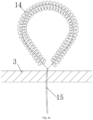
- any one of the fixing mechanisms includes a fixing knot 14 and a traction wire 15, the traction wire 15 is mounted on the fixing knot 14, two ends of the traction wire 15 are located outside a proximal end of the fixing knot 14, the puncturing mechanism 1 is used for puncturing the fixing knot 14 and the traction wire 15 of any one of the fixing mechanisms onto an annulus, so that the fixing knot 14 is located on one side (for example, located on a side of a left atrium) of the annulus and the two ends of the traction wire are located on the other side (for example, located on a side of a left ventricle) of the annulus, as shown in Fig. 11a .
- Traction wires 15 of two adjacent fixing mechanisms are driven by a traction force to approach each other so as to shorten a distance between two adjacent fixing knots 14, so that an annulus portion between the two adjacent fixing knots 14 is bent or creased, a circumferential length of the annulus is reduced, as shown in Fig.
- the locking mechanism 2 is used to lock end parts of the traction wires 15 in the two adjacent fixing mechanisms to the annulus, so that the annulus is kept in a state in which the inner hole is shrunken, and as the size of the inner hole of the annulus is reduced, the annulus is closed more easily, thereby solving the problem of incomplete closing of the annulus and achieving a repair effect.
- the locking mechanism 2 includes a locking body 21 and a locking plug 22.
- the locking body 21 has a first channel extending in a length direction of the locking body; the locking plug 22 is inserted into the first channel so as to clamp the traction wires 15 between the locking plug 22 and the locking body 21, at the moment, the two ends of the traction wires 15 need to extend out of a proximal end of the locking body 21, so as to lock the traction wires 15 onto the locking body 21, and the adjusted distance between the two fixing knots 14 remains.
- the locking plug 22 only needs to be inserted into the locking body 21 from a proximal end to a far end.
- a locking hole 27 through which the ends of the traction wires 15 pass is formed in a side wall of the locking body 21.
- the two ends of the traction wires 15 pass through the locking hole 27 after passing through the first channel and then adjust the distance between the two fixing knots 14 by applying a traction force to the traction wires 15, after the distance is adjusted in place, the locking plug 22 is inserted into the locking body 21, and by forming the locking hole 27, the two ends of the traction wires 15 do not need to extend out of the proximal end of the first channel and only need to extend out of the locking hole 27, which is also convenient for applying the traction force to the traction wires 15.
- a first mounting hole 213 is also formed in the side wall of the locking body 21; the locking mechanism 2 further includes at least one elastomer 26, a proximal end of the elastomer 26 is formed in the first mounting hole 213, and a far end of the elastomer tends to extend into the first channel under an action of an own deformation amount; and the elastomer 26 swings towards an inside of the first mounting hole 213 under an extrusion force of an outer wall of the locking plug 22 in a case that the locking plug 22 is inserted towards the first channel, and after the locking plug 22 crosses the far end of the elastomer 26, the elastomer 26 is restored and the far end of the elastomer is blocked onto the locking plug 22, so as to limit the proximal end of the locking plug 22 onto the locking body 21 and avoid sliding out from the proximal end of the locking body 21.
- the locking plug 22 includes a base 222 and a first annular boss 221 formed on a periphery of a far end of the base 222, and the first annular boss 211 applies an extrusion force to the elastomer 26; and the far end of the elastomer 26 is blocked onto a side of a proximal end of the first annular boss 221 in a case that the elastomer 26 is restored, so as to achieve a blocking force for the locking plug 22.
- only the far end of the base 222 and the first annular boss 221 may also be arranged, and an end surface of the first annular boss 221 is used as a proximal end surface of the locking plug 22.
- the locking body 21 and the elastomer 26 are integrally formed, preferably, a nickel-titanium alloy material, or other medical deformable alloy material or a memory alloy material is used.
- the elastomer 26 preferably, the elastomer 26 is an elastic piece or a spring.
- a rubber material is used for forming a rubber plug, or another medical high molecular material is used.
- a second annular boss 211 protruding inwards is arranged on an inner wall of the far end of the locking body 21; and a far end of the first annular boss 221 is maintained between the second annular boss 211 and the elastomer 26 under blocking of the second annular boss 211. That is, after the locking plug 22 slides in place on the locking body 21, under cooperation of the second annular boss 211 and the elastomer 26, the locking plug 22 is limited on the locking body 21, and the locking plug 22 cannot move relative to the locking body 21, so as to further guarantee the locking effect on the traction wires 15.
- Shapes of the above first channel and the first mounting hole 213 are optimally round holes or certainly may also be holes in other shapes, such as, rectangular holes or elliptical holes or holes in other shapes.
- the above locking mechanism 2 further includes a conveying mechanism 21 for conveying the locking body 21 and the locking plug 22; and the conveying mechanism includes an outer tube 24, a hanging sheath 23 slidably arranged in the outer tube 24 and a push inner tube 25 slidably arranged in the hanging sheath 23.
- a far end of the hanging sheath 23 is detachably connected with the proximal end of the locking body 21, and a far end of the push inner tube 25 is inserted into an inner hole of a proximal end of the locking plug 22 or sleeves the proximal end of the locking plug 22; and both the locking body 21 and the locking plug 22 are located in the outer tube 24 before the locking body 21 is not released.
- the whole conveying mechanism is transapically conveyed to nearby the mitral valve annulus, the outer tube 24 stops moving, the hanging sheath 23 pushes the locking body 21 to cause the locking body 21 to extend out of the far end of the outer tube 24, and the hanging sheath 23 is separated from the locking body 21.
- the ends of the traction wires 15 are punctured in the locking hole 27, the traction force is applied to the ends of the traction wires 15 so as to adjust the distance between the two fixing knots 14, after the distance between the two fixing knots 14 is adjusted in place, the push inner tube 25 pushes the locking plug to be inserted into the locking body 21, and then in view of the limiting effect of the elastomer 26, the push inner tube 25 is withdrawn and is separated from locking, and finally, the whole conveying mechanism is withdrawn from a human body by withdrawing the outer tube 24.
- two notch grooves 212 which are in symmetric distribution are arranged on the proximal end of the locking body 21, and correspondingly, an ear hanger (not shown in Figure) suitable for being clamped into each ear hanger notch is arranged at the far end of the hanging sheath 23; before releasing, the ear hanger remains clamped into the notch grooves 212 under a radial restraining force of the outer tube 24; and when the hanging sheath 23 extends out of the outer tube 24, the ear hanger is restored under an action of an own deformation amount, tends to swing outwards and exit from the notch grooves 212, so that separation of the hanging sheath 23 from the locking body 21 is implemented.
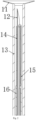
- the puncturing mechanism 1 includes an outer sheath 13, a puncture needle 12 and a push sheath 16.
- the puncture needle 12 is slidably arranged in the outer sheath 13, a notch channel 121 extending in a length direction of the puncture needle 12 is formed in an outer wall of a far end of the puncture needle 12, and the push sheath 16 is slidably arranged in the outer sheath 13 to sleeve the puncture needle.
- the fixing knots 14 have a folded state of being folded into the outer sheath 13 and a released state of being punctured onto the annulus.
- the fixing knots 14 sleeve an outer wall of the notch channel 121 of the puncture needle, a proximal end of the puncture needle and a far end of the push sheath 16 are distributed oppositely, a first end of each traction wire 15 is located in the notch channel 121, and a second end of each traction wire 15 passes through the notch channel 121, then is winded onto an outer wall of the fixing knot 14 from a far end of the fixing knot 14 and extends into the puncture needle via a proximal end of the notch channel 121 so as to overlap the first end and the second end; and end parts of the traction wires 15 which are in overlay distributed may extend out of the proximal end of the puncture needle, so that an operator conveniently applies the traction force to the traction wires
- a notch 122 sinking inwards is formed in a side wall of the notch channel 121 of the puncture needle 12; and in the folded state, the far ends of the fixing knots 14 sleeve the notch 122, and the second ends of the traction wires 15 are winded on the outer walls of the fixing knots 14 after passing through the notch 122, so that the fixing knots 14 and the traction wires 15 are conveniently positioned.
- a fixing head end 11 is arranged on an end face of the far end of the outer sheath 13 and is in a trumpet shape from a proximal end to a far end of the fixing head end, so that an abutting area of the fixing head end 11 on the mitral valve annulus is increased, the annulus may be supported in a direction towards the atrium, and subsequent puncturing of the puncture needle 12 is convenient.
- the fixing head end 11 is made of a medical high molecular material, has certain softness and can protect the annulus from being broken. For example, a nickel-titanium alloy or another memory alloy material may be used.
- the fixing knot 14 may be a spiral tube, namely, a spring-like tube; or as shown in Fig. 1 , the fixing knot 14 may be directly a round tube.
- the fixing knot 14 uses polytetrafluoroethylene (ePTFE) or a nickel-titanium alloy or another medical high molecular or degradable material, has a certain deformation amount for conveniently forming the ring shape after subsequently puncturing in place, and a circular arc surface makes contact with human organ and does not damage the organ making contact with the circular arc surface.
- ePTFE polytetrafluoroethylene
- nickel-titanium alloy nickel-titanium alloy
- another medical high molecular or degradable material has a certain deformation amount for conveniently forming the ring shape after subsequently puncturing in place, and a circular arc surface makes contact with human organ and does not damage the organ making contact with the circular arc surface.
- the puncture needle 12 of the annulus is made of high-strength metal with a head being ground at a certain angle.
- the push sheath 16 is made of a metal material or a high molecular material, preferably, the traction wires 15 are made of polytetrafluoroethylene (ePTFE) or another high molecular material.
- the ring contraction apparatus for the mitral valve annulus in the optimal implementation of this embodiment may achieve small incision insertion while the heart beats continuously, the dilated annulus is repaired, and a working process is explained by taking annulus repair between the left atrium and the left ventricle.
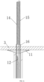
- Fig. 10 it enters the left ventricle by cardiac apex puncturing, the outer sheath 13 is delivered to below the mitral valve annulus 3, the fixing head end 11 abuts against the annulus, the annulus is pushed in a direction towards the left atrium, and a puncture point of the annulus is fixed by using an end surface of the far end of the fixing head end after adjusting the direction, as shown in Fig. 4a .
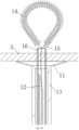
- the outer sheath 13 remains static, the puncture needle 12, the fixing knots 14, the traction wires 15 and the push sheath 16 push and puncture the annulus together forwards (in the direction towards the left atrium), the puncture needle 12, the traction wires 15 and push sheath 16 are punctured on the annulus, and the fixing knots 14 are located on a side of the left atrium, as shown in Fig. 4b ; then, the puncture needle 12 is withdrawn firstly, and then a push tube remains pushing the proximal ends of the fixing knots 14, as shown in Fig.
- the locking mechanism 2 is delivered to the annulus by using the conveying mechanism, the outer tube 24 is conveyed to the mitral valve annulus 3 through transapical puncture, the outer tube 24 stops moving, the hanging sheath 23 moves to push the locking body 21 to a bottom of the mitral valve annulus 3, the end parts of the traction wires 15 of the two adjacent fixing knots 14 pass through the locking hole 27 via the first channel of the locking body 21 to extend towards the proximal end; then, the traction force is applied to the traction wires 15 through three-dimensional ultrasound and contrast navigation, the distance between the two annulus fixing knots 14 is adjusted in real time till reflux disappears, for example, the distance between the two fixing knots 14 is finally adjusted to L2, a circumferential length of the mitral valve annulus 3 is shortened, and thus, narrowing of the annulus is achieved; at the moment, the locking plug 22 is pushed to the farthest end of the locking body 21 through the push inner tube 25, the elastic piece plays a role in blocking the locking plug 22, the
- a plurality of pairs of fixing knots 14 may be implanted on the mitral valve annulus 3 in the above same manner to further reduce a size of the annulus.
- the number of fixing mechanisms is an even number, a pair of fixing mechanisms may implement a ring contraction function of the annulus, and the specific set number is not limited and may be selected according to actual demands.
- a knotting position of the two ends of the traction wires 15 of each fixing knot 14 above is close to a position of the annulus, and the traction wires 15 may also be knotted and fixed at a cardiac apex according to a lesion of a patient to complete implantation and securing of the ring contraction apparatus.
Landscapes
- Health & Medical Sciences (AREA)
- Cardiology (AREA)
- Life Sciences & Earth Sciences (AREA)
- General Health & Medical Sciences (AREA)
- Public Health (AREA)
- Biomedical Technology (AREA)
- Heart & Thoracic Surgery (AREA)
- Engineering & Computer Science (AREA)
- Animal Behavior & Ethology (AREA)
- Veterinary Medicine (AREA)
- Surgery (AREA)
- Transplantation (AREA)
- Oral & Maxillofacial Surgery (AREA)
- Vascular Medicine (AREA)
- Nuclear Medicine, Radiotherapy & Molecular Imaging (AREA)
- Medical Informatics (AREA)
- Molecular Biology (AREA)
- Pathology (AREA)
- Rheumatology (AREA)
- Prostheses (AREA)
Applications Claiming Priority (1)
| Application Number | Priority Date | Filing Date | Title |
|---|---|---|---|
| PCT/CN2021/095110 WO2022241755A1 (zh) | 2021-05-21 | 2021-05-21 | 二尖瓣瓣环的环缩装置 |
Publications (3)
| Publication Number | Publication Date |
|---|---|
| EP4335411A1 true EP4335411A1 (de) | 2024-03-13 |
| EP4335411A4 EP4335411A4 (de) | 2024-06-26 |
| EP4335411B1 EP4335411B1 (de) | 2025-08-27 |
Family
ID=84141070
Family Applications (1)
| Application Number | Title | Priority Date | Filing Date |
|---|---|---|---|
| EP21940208.8A Active EP4335411B1 (de) | 2021-05-21 | 2021-05-21 | Ringkontraktionsvorrichtung für mitralklappenannulus |
Country Status (3)
| Country | Link |
|---|---|
| US (1) | US20240238093A1 (de) |
| EP (1) | EP4335411B1 (de) |
| WO (1) | WO2022241755A1 (de) |
Families Citing this family (2)
| Publication number | Priority date | Publication date | Assignee | Title |
|---|---|---|---|---|
| CN116236261B (zh) * | 2023-05-04 | 2023-07-25 | 科瑞迈吉(北京)医疗科技有限公司 | 一种用于瓣膜修复的穿刺针辅助植入系统 |
| CN116831654A (zh) * | 2023-07-07 | 2023-10-03 | 陕西福泰医疗科技有限公司 | 一种组合式牵拉器、牵拉缝合器及牵拉穿刺器 |
Family Cites Families (11)
| Publication number | Priority date | Publication date | Assignee | Title |
|---|---|---|---|---|
| US5364407A (en) * | 1994-03-21 | 1994-11-15 | Poll Wayne L | Laparoscopic suturing system |
| US20050125011A1 (en) * | 2001-04-24 | 2005-06-09 | Spence Paul A. | Tissue fastening systems and methods utilizing magnetic guidance |
| US7699892B2 (en) * | 2006-04-12 | 2010-04-20 | Medtronic Vascular, Inc. | Minimally invasive procedure for implanting an annuloplasty device |
| US8845723B2 (en) * | 2007-03-13 | 2014-09-30 | Mitralign, Inc. | Systems and methods for introducing elements into tissue |
| KR20110084911A (ko) * | 2008-10-10 | 2011-07-26 | 가이디드 딜리버리 시스템즈 인코퍼레이티드 | 종결 장치 및 관련 방법 |
| JP5960131B2 (ja) * | 2010-06-29 | 2016-08-02 | ジンテス ゲゼルシャフト ミット ベシュレンクテル ハフツング | アンカアセンブリ用の挿入器具 |
| CA2979817C (en) * | 2015-03-18 | 2023-03-28 | Mitralign, Inc. | Tissue anchors and percutaneous tricuspid valve repair using a tissue anchor |
| WO2017059426A1 (en) * | 2015-10-02 | 2017-04-06 | Harpoon Medical, Inc. | Distal anchor apparatus and methods for mitral valve repair |
| US10765515B2 (en) * | 2017-04-06 | 2020-09-08 | University Of Maryland, Baltimore | Distal anchor apparatus and methods for mitral valve repair |
| CN109498216A (zh) * | 2018-12-25 | 2019-03-22 | 乐普(北京)医疗器械股份有限公司 | 一种用于瓣膜修复的牵拉线锁定导管 |
| CN109498217B (zh) * | 2019-02-13 | 2021-07-06 | 上海形状记忆合金材料有限公司 | 经心尖人工腱索修复系统 |
-
2021
- 2021-05-21 EP EP21940208.8A patent/EP4335411B1/de active Active
- 2021-05-21 WO PCT/CN2021/095110 patent/WO2022241755A1/zh not_active Ceased
- 2021-05-21 US US18/562,655 patent/US20240238093A1/en active Pending
Also Published As
| Publication number | Publication date |
|---|---|
| US20240238093A1 (en) | 2024-07-18 |
| WO2022241755A1 (zh) | 2022-11-24 |
| EP4335411A4 (de) | 2024-06-26 |
| EP4335411B1 (de) | 2025-08-27 |
Similar Documents
| Publication | Publication Date | Title |
|---|---|---|
| US10799355B2 (en) | Apical implantation mitral valve balloon closure plate blocking body and implantation method | |
| KR102566728B1 (ko) | 심장 판막 밀봉 장치 및 그를 위한 전달 장치 | |
| US11007060B2 (en) | Transapically-implanted mitral valve flexible coaptation plate blocking body and implantation method | |
| CN114848235B (zh) | 用于心脏瓣膜的假体间隔件装置 | |
| ES3061170T3 (en) | Heart valve sealing devices and delivery devices therefor | |
| US20240366210A1 (en) | Beveled tissue anchor delivery needles | |
| CN108472138B (zh) | 用于经导管治疗瓣膜返流的装置、系统和方法 | |
| US11395735B2 (en) | Valve stent and valve prosthesis | |
| CN112654332A (zh) | 用于瓣膜关闭不全的经导管人工瓣尖 | |
| BR122020025121B1 (pt) | Dispositivo de encaixe para acoplar uma válvula protética e método de recuperação de um dispositivo de encaixe | |
| CN115190786A (zh) | 瓣环成形术设备 | |
| CN115190785A (zh) | 瓣环成形术设备 | |
| CN115884801A (zh) | 铆钉对接平台,封堵器 | |
| JP2025509379A (ja) | デュアルフレームシャント | |
| WO2022057799A1 (en) | Artificial Heart Valve Stent, Artificial Heart Valve and Artificial Heart Valve Replacement System | |
| EP4335411A1 (de) | Ringkontraktionsvorrichtung für mitralklappenannulus | |
| JP2024522730A (ja) | 心臓弁修復補綴物、送達デバイス、および方法 | |
| CN114939005A (zh) | 一种轨道式二尖瓣假体植入系统及其操作方法 | |
| US20190336286A1 (en) | Ring-based prosthetic cardiac valve | |
| US20240423798A1 (en) | Flexible valve anchors | |
| CN214857834U (zh) | 二尖瓣瓣环的环缩装置 | |
| BR122021007127B1 (pt) | Dispositivo de reparo de válvula para reparar uma válvula natural de um paciente |
Legal Events
| Date | Code | Title | Description |
|---|---|---|---|
| STAA | Information on the status of an ep patent application or granted ep patent |
Free format text: STATUS: THE INTERNATIONAL PUBLICATION HAS BEEN MADE |
|
| PUAI | Public reference made under article 153(3) epc to a published international application that has entered the european phase |
Free format text: ORIGINAL CODE: 0009012 |
|
| STAA | Information on the status of an ep patent application or granted ep patent |
Free format text: STATUS: REQUEST FOR EXAMINATION WAS MADE |
|
| 17P | Request for examination filed |
Effective date: 20231206 |
|
| AK | Designated contracting states |
Kind code of ref document: A1 Designated state(s): AL AT BE BG CH CY CZ DE DK EE ES FI FR GB GR HR HU IE IS IT LI LT LU LV MC MK MT NL NO PL PT RO RS SE SI SK SM TR |
|
| A4 | Supplementary search report drawn up and despatched |
Effective date: 20240527 |
|
| RIC1 | Information provided on ipc code assigned before grant |
Ipc: A61B 17/00 20060101ALN20240521BHEP Ipc: A61B 17/04 20060101ALI20240521BHEP Ipc: A61B 17/34 20060101ALI20240521BHEP Ipc: A61F 2/24 20060101AFI20240521BHEP |
|
| DAV | Request for validation of the european patent (deleted) | ||
| DAX | Request for extension of the european patent (deleted) | ||
| GRAP | Despatch of communication of intention to grant a patent |
Free format text: ORIGINAL CODE: EPIDOSNIGR1 |
|
| STAA | Information on the status of an ep patent application or granted ep patent |
Free format text: STATUS: GRANT OF PATENT IS INTENDED |
|
| RIC1 | Information provided on ipc code assigned before grant |
Ipc: A61B 17/00 20060101ALN20250311BHEP Ipc: A61B 17/04 20060101ALI20250311BHEP Ipc: A61B 17/34 20060101ALI20250311BHEP Ipc: A61F 2/24 20060101AFI20250311BHEP |
|
| INTG | Intention to grant announced |
Effective date: 20250320 |
|
| GRAS | Grant fee paid |
Free format text: ORIGINAL CODE: EPIDOSNIGR3 |
|
| GRAA | (expected) grant |
Free format text: ORIGINAL CODE: 0009210 |
|
| STAA | Information on the status of an ep patent application or granted ep patent |
Free format text: STATUS: THE PATENT HAS BEEN GRANTED |
|
| AK | Designated contracting states |
Kind code of ref document: B1 Designated state(s): AL AT BE BG CH CY CZ DE DK EE ES FI FR GB GR HR HU IE IS IT LI LT LU LV MC MK MT NL NO PL PT RO RS SE SI SK SM TR |
|
| REG | Reference to a national code |
Ref country code: CH Ref legal event code: EP |
|
| REG | Reference to a national code |
Ref country code: DE Ref legal event code: R096 Ref document number: 602021037491 Country of ref document: DE |
|
| REG | Reference to a national code |
Ref country code: IE Ref legal event code: FG4D |
|
| REG | Reference to a national code |
Ref country code: NL Ref legal event code: MP Effective date: 20250827 |
|
| PG25 | Lapsed in a contracting state [announced via postgrant information from national office to epo] |
Ref country code: IS Free format text: LAPSE BECAUSE OF FAILURE TO SUBMIT A TRANSLATION OF THE DESCRIPTION OR TO PAY THE FEE WITHIN THE PRESCRIBED TIME-LIMIT Effective date: 20251227 |
|
| PG25 | Lapsed in a contracting state [announced via postgrant information from national office to epo] |
Ref country code: NO Free format text: LAPSE BECAUSE OF FAILURE TO SUBMIT A TRANSLATION OF THE DESCRIPTION OR TO PAY THE FEE WITHIN THE PRESCRIBED TIME-LIMIT Effective date: 20251127 |
|
| REG | Reference to a national code |
Ref country code: LT Ref legal event code: MG9D |
|
| PG25 | Lapsed in a contracting state [announced via postgrant information from national office to epo] |
Ref country code: PT Free format text: LAPSE BECAUSE OF FAILURE TO SUBMIT A TRANSLATION OF THE DESCRIPTION OR TO PAY THE FEE WITHIN THE PRESCRIBED TIME-LIMIT Effective date: 20251229 |
|
| PG25 | Lapsed in a contracting state [announced via postgrant information from national office to epo] |
Ref country code: FI Free format text: LAPSE BECAUSE OF FAILURE TO SUBMIT A TRANSLATION OF THE DESCRIPTION OR TO PAY THE FEE WITHIN THE PRESCRIBED TIME-LIMIT Effective date: 20250827 |
|
| PG25 | Lapsed in a contracting state [announced via postgrant information from national office to epo] |
Ref country code: HR Free format text: LAPSE BECAUSE OF FAILURE TO SUBMIT A TRANSLATION OF THE DESCRIPTION OR TO PAY THE FEE WITHIN THE PRESCRIBED TIME-LIMIT Effective date: 20250827 Ref country code: NL Free format text: LAPSE BECAUSE OF FAILURE TO SUBMIT A TRANSLATION OF THE DESCRIPTION OR TO PAY THE FEE WITHIN THE PRESCRIBED TIME-LIMIT Effective date: 20250827 |
|
| PG25 | Lapsed in a contracting state [announced via postgrant information from national office to epo] |
Ref country code: GR Free format text: LAPSE BECAUSE OF FAILURE TO SUBMIT A TRANSLATION OF THE DESCRIPTION OR TO PAY THE FEE WITHIN THE PRESCRIBED TIME-LIMIT Effective date: 20251128 |
|
| PG25 | Lapsed in a contracting state [announced via postgrant information from national office to epo] |
Ref country code: SE Free format text: LAPSE BECAUSE OF FAILURE TO SUBMIT A TRANSLATION OF THE DESCRIPTION OR TO PAY THE FEE WITHIN THE PRESCRIBED TIME-LIMIT Effective date: 20250827 |
|
| PG25 | Lapsed in a contracting state [announced via postgrant information from national office to epo] |
Ref country code: LV Free format text: LAPSE BECAUSE OF FAILURE TO SUBMIT A TRANSLATION OF THE DESCRIPTION OR TO PAY THE FEE WITHIN THE PRESCRIBED TIME-LIMIT Effective date: 20250827 |
|
| PG25 | Lapsed in a contracting state [announced via postgrant information from national office to epo] |
Ref country code: BG Free format text: LAPSE BECAUSE OF FAILURE TO SUBMIT A TRANSLATION OF THE DESCRIPTION OR TO PAY THE FEE WITHIN THE PRESCRIBED TIME-LIMIT Effective date: 20250827 Ref country code: PL Free format text: LAPSE BECAUSE OF FAILURE TO SUBMIT A TRANSLATION OF THE DESCRIPTION OR TO PAY THE FEE WITHIN THE PRESCRIBED TIME-LIMIT Effective date: 20250827 |
|
| PG25 | Lapsed in a contracting state [announced via postgrant information from national office to epo] |
Ref country code: RS Free format text: LAPSE BECAUSE OF FAILURE TO SUBMIT A TRANSLATION OF THE DESCRIPTION OR TO PAY THE FEE WITHIN THE PRESCRIBED TIME-LIMIT Effective date: 20251127 |
|
| PG25 | Lapsed in a contracting state [announced via postgrant information from national office to epo] |
Ref country code: ES Free format text: LAPSE BECAUSE OF FAILURE TO SUBMIT A TRANSLATION OF THE DESCRIPTION OR TO PAY THE FEE WITHIN THE PRESCRIBED TIME-LIMIT Effective date: 20250827 |
|
| REG | Reference to a national code |
Ref country code: AT Ref legal event code: MK05 Ref document number: 1829114 Country of ref document: AT Kind code of ref document: T Effective date: 20250827 |
|
| PG25 | Lapsed in a contracting state [announced via postgrant information from national office to epo] |
Ref country code: SM Free format text: LAPSE BECAUSE OF FAILURE TO SUBMIT A TRANSLATION OF THE DESCRIPTION OR TO PAY THE FEE WITHIN THE PRESCRIBED TIME-LIMIT Effective date: 20250827 |
|
| PG25 | Lapsed in a contracting state [announced via postgrant information from national office to epo] |
Ref country code: DK Free format text: LAPSE BECAUSE OF FAILURE TO SUBMIT A TRANSLATION OF THE DESCRIPTION OR TO PAY THE FEE WITHIN THE PRESCRIBED TIME-LIMIT Effective date: 20250827 |
|
| PG25 | Lapsed in a contracting state [announced via postgrant information from national office to epo] |
Ref country code: AT Free format text: LAPSE BECAUSE OF FAILURE TO SUBMIT A TRANSLATION OF THE DESCRIPTION OR TO PAY THE FEE WITHIN THE PRESCRIBED TIME-LIMIT Effective date: 20250827 |
|
| PG25 | Lapsed in a contracting state [announced via postgrant information from national office to epo] |
Ref country code: IT Free format text: LAPSE BECAUSE OF FAILURE TO SUBMIT A TRANSLATION OF THE DESCRIPTION OR TO PAY THE FEE WITHIN THE PRESCRIBED TIME-LIMIT Effective date: 20250827 |
|
| PG25 | Lapsed in a contracting state [announced via postgrant information from national office to epo] |
Ref country code: CZ Free format text: LAPSE BECAUSE OF FAILURE TO SUBMIT A TRANSLATION OF THE DESCRIPTION OR TO PAY THE FEE WITHIN THE PRESCRIBED TIME-LIMIT Effective date: 20250827 |
|
| PG25 | Lapsed in a contracting state [announced via postgrant information from national office to epo] |
Ref country code: EE Free format text: LAPSE BECAUSE OF FAILURE TO SUBMIT A TRANSLATION OF THE DESCRIPTION OR TO PAY THE FEE WITHIN THE PRESCRIBED TIME-LIMIT Effective date: 20250827 Ref country code: SK Free format text: LAPSE BECAUSE OF FAILURE TO SUBMIT A TRANSLATION OF THE DESCRIPTION OR TO PAY THE FEE WITHIN THE PRESCRIBED TIME-LIMIT Effective date: 20250827 |