EP4335419A2 - Systèmes et procédés d'implant cornéen - Google Patents
Systèmes et procédés d'implant cornéen Download PDFInfo
- Publication number
- EP4335419A2 EP4335419A2 EP23211000.7A EP23211000A EP4335419A2 EP 4335419 A2 EP4335419 A2 EP 4335419A2 EP 23211000 A EP23211000 A EP 23211000A EP 4335419 A2 EP4335419 A2 EP 4335419A2
- Authority
- EP
- European Patent Office
- Prior art keywords
- cutting apparatus
- corneal tissue
- implant
- cornea
- corneal
- Prior art date
- Legal status (The legal status is an assumption and is not a legal conclusion. Google has not performed a legal analysis and makes no representation as to the accuracy of the status listed.)
- Pending
Links
Images


Classifications
-
- A—HUMAN NECESSITIES
- A61—MEDICAL OR VETERINARY SCIENCE; HYGIENE
- A61F—FILTERS IMPLANTABLE INTO BLOOD VESSELS; PROSTHESES; DEVICES PROVIDING PATENCY TO, OR PREVENTING COLLAPSING OF, TUBULAR STRUCTURES OF THE BODY, e.g. STENTS; ORTHOPAEDIC, NURSING OR CONTRACEPTIVE DEVICES; FOMENTATION; TREATMENT OR PROTECTION OF EYES OR EARS; BANDAGES, DRESSINGS OR ABSORBENT PADS; FIRST-AID KITS
- A61F2/00—Filters implantable into blood vessels; Prostheses, i.e. artificial substitutes or replacements for parts of the body; Appliances for connecting them with the body; Devices providing patency to, or preventing collapsing of, tubular structures of the body, e.g. stents
- A61F2/02—Prostheses implantable into the body
- A61F2/14—Eye parts, e.g. lenses or corneal implants; Artificial eyes
- A61F2/142—Cornea, e.g. artificial corneae, keratoprostheses or corneal implants for repair of defective corneal tissue
-
- A—HUMAN NECESSITIES
- A61—MEDICAL OR VETERINARY SCIENCE; HYGIENE
- A61F—FILTERS IMPLANTABLE INTO BLOOD VESSELS; PROSTHESES; DEVICES PROVIDING PATENCY TO, OR PREVENTING COLLAPSING OF, TUBULAR STRUCTURES OF THE BODY, e.g. STENTS; ORTHOPAEDIC, NURSING OR CONTRACEPTIVE DEVICES; FOMENTATION; TREATMENT OR PROTECTION OF EYES OR EARS; BANDAGES, DRESSINGS OR ABSORBENT PADS; FIRST-AID KITS
- A61F2/00—Filters implantable into blood vessels; Prostheses, i.e. artificial substitutes or replacements for parts of the body; Appliances for connecting them with the body; Devices providing patency to, or preventing collapsing of, tubular structures of the body, e.g. stents
- A61F2/02—Prostheses implantable into the body
- A61F2/14—Eye parts, e.g. lenses or corneal implants; Artificial eyes
- A61F2/145—Corneal inlays, onlays, or lenses for refractive correction
-
- A—HUMAN NECESSITIES
- A61—MEDICAL OR VETERINARY SCIENCE; HYGIENE
- A61F—FILTERS IMPLANTABLE INTO BLOOD VESSELS; PROSTHESES; DEVICES PROVIDING PATENCY TO, OR PREVENTING COLLAPSING OF, TUBULAR STRUCTURES OF THE BODY, e.g. STENTS; ORTHOPAEDIC, NURSING OR CONTRACEPTIVE DEVICES; FOMENTATION; TREATMENT OR PROTECTION OF EYES OR EARS; BANDAGES, DRESSINGS OR ABSORBENT PADS; FIRST-AID KITS
- A61F9/00—Methods or devices for treatment of the eyes; Devices for putting in contact-lenses; Devices to correct squinting; Apparatus to guide the blind; Protective devices for the eyes, carried on the body or in the hand
- A61F9/007—Methods or devices for eye surgery
- A61F9/008—Methods or devices for eye surgery using laser
- A61F9/00825—Methods or devices for eye surgery using laser for photodisruption
- A61F9/00831—Transplantation
-
- A—HUMAN NECESSITIES
- A61—MEDICAL OR VETERINARY SCIENCE; HYGIENE
- A61F—FILTERS IMPLANTABLE INTO BLOOD VESSELS; PROSTHESES; DEVICES PROVIDING PATENCY TO, OR PREVENTING COLLAPSING OF, TUBULAR STRUCTURES OF THE BODY, e.g. STENTS; ORTHOPAEDIC, NURSING OR CONTRACEPTIVE DEVICES; FOMENTATION; TREATMENT OR PROTECTION OF EYES OR EARS; BANDAGES, DRESSINGS OR ABSORBENT PADS; FIRST-AID KITS
- A61F9/00—Methods or devices for treatment of the eyes; Devices for putting in contact-lenses; Devices to correct squinting; Apparatus to guide the blind; Protective devices for the eyes, carried on the body or in the hand
- A61F9/007—Methods or devices for eye surgery
- A61F9/008—Methods or devices for eye surgery using laser
- A61F2009/00861—Methods or devices for eye surgery using laser adapted for treatment at a particular location
- A61F2009/00872—Cornea
-
- A—HUMAN NECESSITIES
- A61—MEDICAL OR VETERINARY SCIENCE; HYGIENE
- A61F—FILTERS IMPLANTABLE INTO BLOOD VESSELS; PROSTHESES; DEVICES PROVIDING PATENCY TO, OR PREVENTING COLLAPSING OF, TUBULAR STRUCTURES OF THE BODY, e.g. STENTS; ORTHOPAEDIC, NURSING OR CONTRACEPTIVE DEVICES; FOMENTATION; TREATMENT OR PROTECTION OF EYES OR EARS; BANDAGES, DRESSINGS OR ABSORBENT PADS; FIRST-AID KITS
- A61F9/00—Methods or devices for treatment of the eyes; Devices for putting in contact-lenses; Devices to correct squinting; Apparatus to guide the blind; Protective devices for the eyes, carried on the body or in the hand
- A61F9/007—Methods or devices for eye surgery
- A61F9/008—Methods or devices for eye surgery using laser
- A61F2009/00885—Methods or devices for eye surgery using laser for treating a particular disease
- A61F2009/00895—Presbyopia
-
- A—HUMAN NECESSITIES
- A61—MEDICAL OR VETERINARY SCIENCE; HYGIENE
- A61F—FILTERS IMPLANTABLE INTO BLOOD VESSELS; PROSTHESES; DEVICES PROVIDING PATENCY TO, OR PREVENTING COLLAPSING OF, TUBULAR STRUCTURES OF THE BODY, e.g. STENTS; ORTHOPAEDIC, NURSING OR CONTRACEPTIVE DEVICES; FOMENTATION; TREATMENT OR PROTECTION OF EYES OR EARS; BANDAGES, DRESSINGS OR ABSORBENT PADS; FIRST-AID KITS
- A61F2240/00—Manufacturing or designing of prostheses classified in groups A61F2/00 - A61F2/26 or A61F2/82 or A61F9/00 or A61F11/00 or subgroups thereof
- A61F2240/001—Designing or manufacturing processes
- A61F2240/002—Designing or making customized prostheses
-
- A—HUMAN NECESSITIES
- A61—MEDICAL OR VETERINARY SCIENCE; HYGIENE
- A61F—FILTERS IMPLANTABLE INTO BLOOD VESSELS; PROSTHESES; DEVICES PROVIDING PATENCY TO, OR PREVENTING COLLAPSING OF, TUBULAR STRUCTURES OF THE BODY, e.g. STENTS; ORTHOPAEDIC, NURSING OR CONTRACEPTIVE DEVICES; FOMENTATION; TREATMENT OR PROTECTION OF EYES OR EARS; BANDAGES, DRESSINGS OR ABSORBENT PADS; FIRST-AID KITS
- A61F9/00—Methods or devices for treatment of the eyes; Devices for putting in contact-lenses; Devices to correct squinting; Apparatus to guide the blind; Protective devices for the eyes, carried on the body or in the hand
- A61F9/007—Methods or devices for eye surgery
- A61F9/008—Methods or devices for eye surgery using laser
- A61F9/00825—Methods or devices for eye surgery using laser for photodisruption
- A61F9/00834—Inlays; Onlays; Intraocular lenses [IOL]
-
- A—HUMAN NECESSITIES
- A61—MEDICAL OR VETERINARY SCIENCE; HYGIENE
- A61F—FILTERS IMPLANTABLE INTO BLOOD VESSELS; PROSTHESES; DEVICES PROVIDING PATENCY TO, OR PREVENTING COLLAPSING OF, TUBULAR STRUCTURES OF THE BODY, e.g. STENTS; ORTHOPAEDIC, NURSING OR CONTRACEPTIVE DEVICES; FOMENTATION; TREATMENT OR PROTECTION OF EYES OR EARS; BANDAGES, DRESSINGS OR ABSORBENT PADS; FIRST-AID KITS
- A61F9/00—Methods or devices for treatment of the eyes; Devices for putting in contact-lenses; Devices to correct squinting; Apparatus to guide the blind; Protective devices for the eyes, carried on the body or in the hand
- A61F9/007—Methods or devices for eye surgery
- A61F9/008—Methods or devices for eye surgery using laser
- A61F9/00825—Methods or devices for eye surgery using laser for photodisruption
- A61F9/00836—Flap cutting
Definitions
- the present disclosure relates generally to systems and methods for correcting vision, and more particularly, to systems and methods that employ implants to reshape the cornea in order to correct vision.
- a variety of eye disorders such as myopia, hyperopia, astigmatism, and presbyopia, involve abnormal shaping of the cornea. This abnormal shaping prevents the cornea from properly focusing light onto the retina in the back of the eye (i.e., refractive error).
- a number of treatments attempt to reshape the cornea so that the light is properly focused.
- LASIK laser-assisted in situ keratomileusis
- LASIK laser-assisted in situ keratomileusis
- embodiments employ implants to reshape the cornea in order to correct vision.
- such embodiments may address the refractive errors associated with eye disorders such as myopia, hyperopia, astigmatism, and presbyopia.
- the implants may be formed from natural tissue, such as donor corneal tissue.
- a system for forming corneal implants includes a first cutting apparatus configured to cut a donor cornea and form a portion of corneal tissue.
- the donor cornea includes an anterior surface and a posterior surface.
- the first cutting apparatus is configured to cut the donor cornea along an axis extending between the anterior surface and the posterior surface.
- the system also includes a second cutting apparatus configured to form a plurality of lenticules from the portion of corneal tissue by making, to the portion of corneal tissue, a series of cuts transverse to the axis. Corneal tissue between consecutive cuts by the second cutting apparatus provides a corresponding lenticule to be shaped for a corneal implant. A distance between the consecutive cuts defines a thickness for the corresponding lenticule.
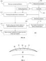
- a method for forming corneal implants includes providing a donor cornea including an anterior surface and a posterior surface.
- the method includes forming, with a first cutting apparatus, a portion of corneal tissue by cutting the donor cornea along an axis extending between the anterior surface and the posterior surface, the method includes forming, with a second cutting apparatus, a plurality of lenticules from the portion of corneal tissue by making, to the portion of corneal tissue, a series of cuts transverse to the axis.
- Corneal tissue between consecutive cuts by the second cutting apparatus provides a corresponding lenticule to be shaped for a corneal implant. A distance between the consecutive cuts defines a thickness for the corresponding lenticule.
- the method may further include freezing the portion of corneal tissue, wherein the second cutting apparatus includes a cryo-microtome configured to cut the frozen portion of corneal tissue.
- the consecutive cuts made by the second cutting apparatus include a first cut made closest to the anterior surface of the donor cornea and a second cut made closest to the posterior surface of the donor cornea.
- the corresponding lenticule includes a first surface formed by the first cut and a second surface formed by the second cut.
- the second cutting apparatus may be further employed to shape at least one of the first surface or the second surface of the corresponding lenticule to form the corneal implant with a desired refractive profile.
- Example systems and methods employ implants to reshape the cornea in order to correct vision.
- such embodiments may address the refractive errors associated with eye disorders such as myopia, hyperopia, astigmatism, and presbyopia.
- Example systems and methods employ implants that are formed from natural tissue.
- the implants may be formed from donor corneal tissue.
- the implants may be formed as allografts, i.e., tissue that is transplanted between members of the same species.
- the implants may be formed as xenografts, i.e., tissue that is transplanted between members of different species.
- the methods and implants of the present disclosure exhibit significant improvements over prior attempts to correct vision utilizing implants.
- some prior attempts to correct vision utilized implants made from synthetic materials; however, such implants made from synthetic materials did not work well for a variety of reasons (e.g., the irregularity of the collagen matrix of an eye, differences in the state of hydration of the synthetic material and the collagen matrix of an eye, lack of biocompatibility, etc.).
- the methods and implants of the present disclosure which are made from natural tissue, overcome the deficiencies of such prior attempts.
- the methods and implants of the present disclosure which are made from natural tissue, exhibit greater biocompatibility with a patient's cornea, more closely match the index of refraction of the patient's cornea, can be maintained at a state of hydration that is required for implantation (e.g., a state of hydration that is similar to that of the implantation site), and ensures that sufficient gas and nutrients can be exchanged within the patient's cornea.
- a state of hydration that is required for implantation e.g., a state of hydration that is similar to that of the implantation site
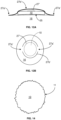
- FIGS. 1A and 1B illustrate an example implant 10 according to aspects of the present disclosure.
- the implant 10 is formed from natural tissue or, more particularly, for example, a donor cornea.
- the implant 10 has a front (anterior) surface 12 corresponding to the anterior of the eye when implanted and a back (posterior) surface 14 corresponding to the posterior of the eye when implanted.
- the example implant 10 illustrated in FIG. 1 has a front surface 12 and back surface 14 that form a meniscus shape
- the implant 10 may have a plano-convex shape, a plano-concave shape, a bi-convex shape, or the like.
- the front surface 12 and/or the back surface 14 may be spherical and/or aspherical.
- FIG. 1B shows a top plan view of the implant 10 having a central region 34, a mid-peripheral region, 36, an outer peripheral region 37, and a peripheral edge 32.
- regions 34, 36, 37 are intended as one non-limiting example and the implants 10 may have any number (i.e., one or more) of regions of any shape and size.
- the example implant 10 illustrated in FIGS. 1A and 1B has a circular perimeter shape defined by the peripheral edge 32, the implant 10 may have an oval shape, a polygonal shape, a non-polygonal shape, or the like.
- the back surface 14 of the implant 10 may be shaped to have a surface profile that generally corresponds to a surface profile of an implantation site of a patient's cornea, and the front surface 12 of the implant 10 may be shaped to have a surface profile that provides a predetermined refractive correction.
- the implant 10 may be precisely custom formed for the patient receiving the implant 10.
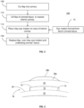
- FIG. 2 illustrates an example procedure 100 for implantation of the implant 10 according to aspects of the present disclosure.
- a flap is formed in a cornea 16.
- a laser e.g., a femtosecond laser
- a mechanical keratome e.g., a mechanical keratome
- other cutting mechanisms e.g., a blade
- the flap may be as thin as flaps that are cut for Sub-Bowman's Keratomileusis.
- the flap is sufficiently large to provide stability and ease of handling.
- the flap of corneal tissue is lifted to expose the corneal interior 18.
- an anterior portion 20 of the cornea 16 is separated from a posterior portion 22 of the cornea 16 to expose a stromal bed 24 upon which the implant 10 can be implanted.
- the implant 10 formed from donor corneal tissue is placed onto the stromal bed 24 at an implantation site in the exposed interior area 18 of the cornea 16 formed in step 105.
- the back surface 14 of the implant 10 is placed into contact with the bed 24 and may have a shape that corresponds to the shape of the bed 24 at the implantation site.
- the back surface 14 of the implant 10 may have a non-flat surface curvature that generally corresponds to the non-flat curvature of the bed 24 at the implantation site.
- the back surface 14 of the implant 10 may be generally flat to correspond with a generally flat bed 24 at the implantation site.
- the flap may have varying thicknesses to combine with the shapes of the implant 10 and the stromal bed 24 to produce the desired corneal shape.
- the implant 10 is implanted into the cornea 16 in a hydrated state.
- the implant 10 may be transferred, via an insertion device (not shown), from a storage media containing the implant 10 prior to the procedure 100 to the implantation site.
- the implant 10 may be transferred from a controlled environment directly and immediately to the implantation site.
- the insertion device may be configured to maintain the implant 10 in the desired hydrated state.
- the flap is replaced over the implant 10 and corneal interior 18. With the flap in place after step 120, the cornea 16 heals and seals the flap of corneal tissue to the rest of the cornea 16 (i.e., the anterior portion 20 seals to the posterior portion 22 to enclose the implant 10).
- the implant 10 is surgically inserted within the interior 18 of the cornea 16 with an anterior portion 20 of corneal tissue 16 disposed over the implant 10.
- the implant 10 is implanted as an inlay implant because it is surgically implanted within the interior 18 of the cornea 16 (i.e., between the anterior portion 20 and a posterior portion 22 of the cornea 16).
- the implant 10 changes the shape of the cornea 16 as evidenced by a change in the anterior corneal surface 26a, 26b (e.g., in FIG. 3 , the anterior corneal surface is shown as a dashed line 26a prior to the implantation and as a solid line 26b after implantation).
- the implant 10 may address the loss of near vision associated with presbyopia.
- the implant 10 may be sized and positioned so that the change to the corneal shape improves near vision while having minimal effect on distance vision, which requires no correction.
- the implants 10 may have any size or shape to produce the necessary desired correction.
- the implant 10 may have a diameter of up to approximately 10 mm, but preferably not more than approximately 7 mm.
- FIGS. 11A-B illustrate an example implantation of the implant 10 employing a flap 27.
- the implant 10 has been received into a corneal bed 25 of the cornea 16 and the flap 27 has been placed over the implant 10.
- the flap 27 is attached to the rest of the cornea 16 at a single portion 27a.
- the remaining edge 27b of the flap 27 has been incised from the cornea 16 and is not attached to the cornea 16.
- the attached portion 27a effectively acts like a hinge.
- the flap 27 When the flap 27 is replaced after implant 10 is received by the bed 25, the flap 27 extends over the implant 10 with the attached portion 27a held down against the rest of the cornea 16. As shown in FIG. 11A , a section 27c of the edge 27b lies opposite the attached portion 27a. Because the opposing section 27c is not attached to the cornea 16, it does not lie flat against the cornea 16 in the same manner as the attached portion 27a. The flap 27 lies over the implant 10 asymmetrically and experiences asymmetric forces. If this asymmetry remains through healing and sealing of the flap 27 along the edge 27b, resulting asymmetric stresses on the anterior surface of the cornea 16 may induce an astigmatic shape for the cornea 16.
- FIGS. 12A-B illustrate a approach for forming an alternative flap 27'.
- the flap 27' includes a plurality of attached portions 27a' that are arranged symmetrically about the flap 27'.
- the flap 27' includes two opposing attached portions 27a', which are both held down and lie flat against the cornea 16 in a similar manner.
- the flap 27 lies over the implant 10 symmetrically and experiences symmetric forces.
- the anterior surface of the cornea 16 is less likely to experience asymmetric stresses that may induce an astigmatic shape for the cornea 16.
- the opposing attached portions 27a' produce equal and opposite stresses on the anterior surface of the cornea 16.
- the implant 10 can be received under the flap 27' via the unattached edge 27b'.
- the flap 27' shown in FIGS. 12A-B includes two attached portions 27a', other embodiments may include more attached portions 27a'.
- the flap 27' may include four attached portions 27a' arranged symmetrically about the flap 27', i.e., at 0°, 90°, 180°, and 270°.
- the flap 27' may have a circular shape, other embodiments may employ other shapes, e.g., oval, rectangular, square, etc.
- the implant 10 may also have other shapes, dimensions, etc.
- the use of symmetrically arranged attached portions may be used with pockets and other approaches for implanting onlay/inlay implants to reduce the likelihood of astigmatic effects.
- the use of implants made from synthetic materials is accompanied by a variety of disadvantages.
- biologic and manufacturing limitations require synthetic implants to have a significant thickness at their periphery. Due to this thickness, the corneal tissue disposed over the synthetic implant experiences a draping effect at the periphery of the implant. This draping effect affects the shape of the cornea (e.g., at the anterior surface) beyond the periphery of the implant.
- the synthetic implant has a particular diameter
- the effect of the synthetic implant on the corneal shape is larger than the particular diameter, i.e., a larger effective zone.
- the synthetic implant must thus be limited to smaller diameters. For instance, the synthetic implant may be required to have a diameter of 4 mm or less. It is very difficult, however, to handle such smaller implants and to align and keep them in position.
- the implants formed from natural tissue according to the present disclosure do not have the biologic and manufacturing limitations of synthetic implants and thus do not experience the same draping effect at their periphery.
- natural implants of larger diameters e.g., greater than 4 mm, may be employed to achieve corrective reshaping.
- the diameter of the natural implant can be larger than the synthetic implant.
- the implant procedure does not have to account for an effective zone that is significantly greater than the diameter of the natural implant.
- the natural implant may have also a skirt that tapers to near-zero thickness at the periphery to minimize further any possible draping effect.
- the corneal tissue is supported by the skirt as the corneal tissue gradually rises and extends inwardly over the natural implant. With the skirt, the anterior surface is not affected beyond the periphery of the natural implant, so the corneal shape change corresponds more predictably to the size of the natural implant.
- the natural implants do not suffer from the disadvantages of the synthetic implants described above.
- the implant 10 shown in FIG. 3 is employed as an inlay implant 10, it is understood that applying the implant 10 to the cornea 16 is not limited to the procedure 100 described above and that other procedures may be employed.
- a pocket having side walls with an opening may be formed (e.g., with a femtosecond laser or other cutting mechanism) to receive the implant 10.
- the cornea 16 can be cut to separate the anterior portion 20 of the cornea 16 (e.g., the flap or an anterior section of a pocket) from the posterior portion 22 of the cornea 16, exposing the corneal interior 18 upon which the implant 10 can then be placed at an implantation site and subsequently covered by the anterior portion 20 of the cornea 16.
- the implant 10 may be employed as an onlay implant, where it is placed on an outer portion 28 of the cornea 16 just under the epithelium 30 so that the epithelium 30 can grow over the implant 10.
- the implant 10 is sutured over the outer portion 28 of the corneal tissue 16 in step 310 where the epithelium 30 is allowed to grow over the implant 10 in step 315.
- the epithelium 30 is removed (e.g., scraped) from the cornea in step 355 and the implant 10 is stably positioned with an adhesive substance over the outer portion 28 of the corneal tissue 16 in step 360 where the epithelium 30 is allowed to grow over the implant 10 in step 365.
- the adhesive substance may be a synthetic, biocompatible hydrogel that creates a temporary, soft, and lubricious surface barrier over the implant 10, keeping the implant 10 in place for the growth of the epithelium 30.
- the adhesive substance can include a cross-linking agent.
- the onlay implant 10 can be dipped into riboflavin to facilitate assist in visualizing placement of the implant 10 on the outer portion 28 of the cornea 16.
- the cross-linking agent can be activated (e.g., via a photoactivating light) to hold the implant 10 to the outer portion 28 of the cornea 16.
- the onlay implant changes the shape of the cornea 16 and results in corrective modification of the cornea 16.
- the onlay implant may be applied to treat all refractive errors.
- the corneal epithelium 30 grows over the onlay implant 10 which is implanted on the outer portion 28 of the corneal tissue 16.
- the epithelium 30 is generally about 50 micrometers (i.e., 5-6 cell layers) thick and generally regenerates when the cornea 16 is damaged or partially removed.
- the shape of the implant 10 is configured to facilitate the advancement of the epithelium 30 smoothly over the implant 10 during regeneration.
- the implant 10 can have a tapered profile at the outer peripheral region 37 such that the implant 10 becomes thinner from the mid-periphery region 36 towards the peripheral edge 32 of the implant 10. Formed from donor corneal tissue, the implant 10 advantageously promotes effective growth of the epithelium 30. In addition, the implant 10 provides the accuracy required to achieve the desired correction.
- the onlay implant 10 is implanted on an outer portion 28 of the cornea 16 under the corneal epithelium 30.
- the Bowman's membrane is a smooth, acellular, nonregenerating layer, located between the epithelium and the stroma in the cornea of the eye. It is the outermost layer just below the epithelium.
- the onlay implant 10 may be implanted between the Bowman's membrane and the epithelium 30.
- the onlay implant 10 may be implanted between one or more cell layers of the epithelium 30.
- the onlay implant 10 may be implanted such that a minor portion penetrates the Bowman's membrane and/or the stroma so long as a major portion of the onlay implant 10 is located on or above the Bowman's membrane and under the outermost layer of the epithelium 30.
- a slight relief (e.g., cavity) is formed in the Bowman's layer to facilitate positioning of the onlay implant 10 and to help keep the onlay implant 10 in position during healing.
- This approach can be employed to lower the edges of the onlay implant 10, so that epithelial under growth is prevented and the epithelium 30 can grow more easily over the onlay implant 10.
- the cornea may be contained in an environment that allows the cornea 16 to maintain a state that replicates the state of a cornea during conventional LASIK procedure, for instance.
- an ultraviolet femtosecond laser is employed to create a separation between the Bowman's membrane and the epithelium for receiving an implant and reshaping the cornea.
- infrared femtosecond lasers may be employed to form pockets in the stroma, such lasers are not suitable for forming the separation between the Bowman's membrane and the epithelium.
- the epithelium is approximately 50 ⁇ m in thickness and the Bowman's membrane is approximately 8 to 10 ⁇ m in thickness.
- An infrared femtosecond laser can generate a plasma plume of up to 10 to 20 ⁇ m.
- an ultraviolet femtosecond laser generates a plasma plume that is only approximately 2 to 3 ⁇ m.
- an ultraviolet femtosecond laser only the top few microns of the Bowman's membrane can be removed to create the desired separation between the Bowman's membrane and the epithelium.
- monitoring technologies such as optical coherence tomography (OCT) may be employed to locate the Bowman's membrane more accurately and guide the focus of the laser to the appropriate location.
- OCT optical coherence tomography
- a laser is employed to create a pocket within the epithelium, close to the Bowman's membrane.
- a cutting instrument can then be inserted into the pocket to clean/separate the Bowman's membrane layer from the residual epithelium layers.
- the pocket is thus prepared to receive an implant.
- the implant 10 (i.e., as an inlay or as an onlay) can be shaped to accommodate a single zone of power for vision correction.
- the implant 10 can be shaped primarily to accommodate near-vision.
- the implant 10 can be shaped to accommodate mid-vision or far-vision.
- the implant 10 can be shaped to provide multi-focality, e.g., accommodate more than one zone of different power.
- the implant 10 can include a plurality of different portions that are each shaped to accommodate a different zone of power. While the implant 10 illustrated in FIG.
- the implant 10 can have any other number of regions, each having a different power.
- the central region 34 of the implant 10 may be shaped to accommodate near-vision
- the mid-peripheral region 36 of the implant 10 may be shaped to accommodate mid-vision
- the outer peripheral region 37 of the implant 10 may be shaped to accommodate far-vision.
- a single implant 10 may be shaped with varying contours to induce regional corneal shape changes that treat a combination of disorders.
- the implant 10 can be shaped to treat presbyopia in combination with myopia or hyperopia. Indeed, most people requiring correction for presbyopia are also ametropic.
- the implant 10 may have a shape is raised at the periphery with a cavity/hole in the center, allowing for some steepness in the center of the cornea.
- the implant 10 may have a shape that is convex at the periphery but has a raised center portion.
- a custom implant 10 i.e., an inlay or an onlay
- the implant 10 may be formed to have a front surface 12 that generally reproduces the back surface 14 curvature.
- the implant 10 may be relatively thinner over areas of the cornea 16 that are relatively higher (i.e., extend outwardly), and vice versa.
- FIG. 6 A non-limiting example of an onlay implant 10 that having a back surface 14 that is the inverse of the surface irregularities 38 of the outer portion 28 of the cornea 16 is illustrated in FIG. 6 .
- the implant 10 may even have an aperture 40 that is positioned over steep and high portions of the cornea 16.
- FIGS. 7A-7B illustrate a non-limiting example of an onlay implant 10 having an aperture 40 over a steep and high portion 42 of the outer portion 28 of the cornea 16.
- the implant 10 may be implanted as an inlay or an onlay according to the techniques described above.
- Example embodiments may compensate for the defocus shift of the eye's optics associated with the transformation of the corneal shape caused by an implant.
- the example embodiments may consider the equations presented by Smith et al., "Effect of defocus on on-axis wave aberration of a centered optical system," Journal of the Optical Society of America A: Optics, Image Science, and Vision (2006), Vol. 23, Issue 11, pp. 2686-2689 , the contents of which are incorporated entirely herein by reference.
- the patient may observe a glare and halo caused by the edge of the implant.
- a round edge of the implant may cause a diffractive (or other optical) effect that produces a round image on the retina.
- a very large optical zone may be employed so that the halo occurs outside the visual zone. Such a solution, however, cannot be employed with the implant.
- implants according to the present disclosure may be shaped to have a randomly serrated edge rather than a smooth round edge.
- the serrations in the edge may include differently sized peaks, valleys, etc.
- the diffractive (or other optical) effect caused by the edge is diffused and does not create a halo on the retina.
- the implant may include a predefined edge that is structured to produce constructive and destructive interference and to manipulate the focus and depth of field.
- FIG. 14 illustrates, as a simplified example, an implant 10 with an edge 11 (e.g., randomly serrated) designed to minimize glare and halo effect.
- the implants can be precisely produced according to patient specific conditions.
- the implants of the present disclosure can be manufactured to have a shape that generally corresponds to a shape of an implantation site of the patient's cornea, provides a predetermined amount of refractive correction, and/or addresses corneal irregularities.
- Approaches for producing eye implants from donor corneal tissue are described, for instance, in U.S. Patent Application Publication No. 2014/0264980, filed January 10, 2014 , and U.S. Patent Application Publication No. 2017/0027754, filed February 28, 2016 , the contents of these applications being incorporated entirely herein by reference.
- the donor cornea may be delaminated to form a plurality of laminar sheets.
- a plurality of lenticules can then be cut from the laminar sheets and shaped for use as eye implants.
- the laminar sheets may have a thickness of approximately 10 ⁇ m to approximately 50 ⁇ m; however, it should be understood that the laminar sheets can have other thicknesses.
- laminar sheet may refer to a sheet that corresponds to a layer of the cornea defined by the cornea's lamellar structure.
- FIG. 8 illustrates an example delaminating system 500 for delaminating a donor cornea 50.
- the example system 500 includes a delaminating cutting apparatus 510.
- the cutting apparatus 510 includes a light source 512 that generates radiation for dissecting the tissue 50a of the donor cornea 50 via photodisruption, photothermal cavitation, laser spallation, etc.
- the cutting apparatus 510 also includes an optical system 514 that can focus the radiation on the tissue 50a and cut the cornea 50 at a desired depth d below the anterior surface 50b of the cornea 50.
- the cutting apparatus 510 may generate a femtosecond laser to cut the cornea 50.
- the example system 500 includes a holding device 520 that mechanically positions the donor cornea 50 to receive the radiation from the cutting apparatus 510.
- the structure of underlying collagen imposes a concave shape on the cornea 50. If the cornea 50 is compressed and/or experiences other stresses, the cornea 50 may deform from this concave shape. For instance, in some systems that incise the cornea (e.g., ophthalmic surgical systems), an aplanation device is applied to the anterior surface of the cornea to position the cornea relative to the cutting device.
- the aplanation device for instance, may be formed from glass. When the aplanation device is applied, the cornea 50 typically flattens.
- a cornea is flattened by an aplanation device and laminar sheets are obtained by cutting the flattened cornea at the predetermined depth d , the resulting laminar sheets might not have the desired uniform thicknesses due to the structure of the underlying collagen.
- deformation of the cornea 50 may prevent the cutting apparatus 510 from accurately cutting the cornea 50 at the predetermined depth d .
- the holding device 520 in FIG. 8 engages the cornea 50 without substantially deforming the cornea 50.
- the cutting apparatus 510 can cut laminar sheets of more uniform thickness from the cornea 50.
- the aplanation device When an aplanation device is employed to flatten the cornea, the aplanation device can be used as a reference point and the cornea can be cut at a predetermined depth from the aplanation device to obtain laminar sheets of desired thickness.
- an aplanation device may disadvantageously prevent the entire cornea from being used to form the laminar sheets. In other words, the aplanation device may not allow laminar sheets to be cut from sections of the cornea 50 extending fully from limbus to limbus.
- the example system 500 does not employ an aplanation device, so the example system 500 can use more of the cornea 50 and produce eye implants from the cornea 50 more efficiently.
- the example system 500 includes a guide system 530 that can guide the cutting apparatus 510 to cut laminar sheets from limbus to limbus of the cornea 50.
- the guide system 530 can measure a distance D from the cutting apparatus 510 to the cornea 50, e.g., the surface 50b.
- the guide system 530 can communicate this distance measurement to a controller 540 that controls aspects of the cutting apparatus 510.
- the distance measurement provides the cutting apparatus 510 with the necessary reference to align and focus the femtosecond laser at a desired depth within the corneal tissue 50a.
- the femtosecond laser spot can be scanned over the cornea 50 to focus on points at the desired depth within the corneal tissue 50a to cut a laminar sheet extending fully from limbus to limbus.
- an aplanation device is not required in the example system 500 to provide a reference to determine focus depth for the femtosecond laser.
- the concave contour of the posterior surface of the laminar sheet is also known/controlled for subsequent processing.
- the optical system 520 can move the femtosecond laser over a stationary cornea 50
- the holding device 520 in alternative embodiments can move the cornea 50 relative to a stationary irradiation system 520 (similar, for instance, to the operation of a goniometer stage), while the femtosecond laser cuts the cornea 50.
- relative movement between the cornea 50 and the cutting apparatus 510 is guided by the guide system 530 to align and focus the femtosecond laser to the appropriate positions in the corneal tissue 50a to delaminate the cornea 50 at the predetermined depth d .
- the example system 500 may also include a deformation monitoring system 550 that can measure any deformation of the cornea 50 that may occur while the cutting apparatus 510 cuts the cornea 50.
- the monitoring system 540 may employ second harmonic imaging, autofluorescence imaging, Brillouin scattering measurement, and/or x-ray scattering measurement before and during the cutting process to determine any deformation.
- the optical system 514 can be adjusted to account for the deformation and allow the cornea 50 to be cut more accurately at the predetermined depth d .
- the focal depth of a femtosecond laser generated by the illumination system 510 can be adjusted to cut the cornea 50 with the desired thickness.
- the deformation monitoring system 550 can communicate the deformation measurement to the controller 540 which controls aspects of the cutting apparatus 510.
- the cutting apparatus 510 may apply a femtosecond laser also to induce gas bubbles at particular locations in the tissue 50a.
- the gas bubbles provide markers that can be monitored with the monitoring system 540. Movement of the gas bubbles can be measured to determine a deformation of the cornea 50.
- the example system 500 may employ the holding device 520 which does not deform the cornea 50
- aspects of the deformation monitoring system 540 may be employed in systems that employ an aplanation device. Such systems can then make necessary corrections to cut the cornea accurately at desired depths even with the deformation induced by the aplanation device.
- FIG. 13A illustrates an example system 800 for forming a plurality of lenticules 60 from a donor cornea 50.
- the system 800 includes a first cutting apparatus 810 that can cut the donor cornea 50 to form a portion 52 of corneal tissue.
- the donor cornea 50 includes an anterior surface and a posterior surface.
- the first cutting apparatus 810 can cut the donor cornea 50 along an axis extending between the anterior surface and the posterior surface as illustrated in FIG. 13A .
- the portion 52 of corneal tissue may be substantially cylindrical in shape.
- the term "cylindrical” indicates a three-dimensional shape that extends along an axis between two ends and has a substantially uniform circular cross-section transverse to the axis from one end to the other; the surfaces at the two ends are not necessarily planar and may be contoured (e.g., convex, concave, etc.).
- the first cutting apparatus 810 may include a femtosecond laser.
- the first cutting apparatus 810 may include a single blade that is operable to move along the axis and cut the donor cornea 50 from the anterior surface to the posterior surface, where the blade has a shape that defines a cross-section transverse to the axis.
- the blade may be substantially cylindrical so that the portion 52 of corneal tissue is correspondingly substantially cylindrical in shape. In effect, the blade may punch the donor cornea 50 to produce the portion 52 of corneal tissue.
- the first cutting apparatus 810 may include more than one blade that can be applied to the donor cornea 50 in any number of steps to produce three-dimensionally the portion 52 of corneal tissue.
- the system 800 also includes a second cutting apparatus 820 that can make a series of cuts transverse to the axis.
- the second cutting apparatus 810 can form a plurality of lenticules 60 from the portion 52 of corneal tissue.
- the corneal tissue between consecutive cuts by the second cutting apparatus 810 provides a corresponding lenticule 60 to be shaped for a corneal implant.
- the distance between the consecutive cuts defines a thickness for the corresponding lenticule 60.
- the second cutting apparatus 810 may include an ultraviolet femtosecond laser, which provides the advantages described herein.
- the consecutive cuts made by the second cutting apparatus 820 include a first cut made closest to the anterior surface of the donor cornea 50 and a second cut made closest to the posterior surface of the donor cornea 50.
- the corresponding lenticule 60 includes a first surface formed by the first cut and a second surface formed by the second cut.
- the second cutting apparatus 820 e.g., including an ultraviolet femtosecond laser, may shape at least one of the first surface or the second surface of the corresponding lenticule 60 to form an corneal implant with a desired refractive profile.
- the donor cornea 50 may include a plurality of lamellar layers disposed between the anterior surface and the posterior surface, where the lamellar layers are formed by the lamellae in the corneal tissue.
- the first cutting apparatus 810 may cut the donor cornea 50 transversely through the lamellar layers, while the second cutting apparatus 820 can make cuts along the lamellar layers.
- FIG. 13B illustrates an embodiment 800' of the example system 800 for forming a plurality of lenticules 60 from a donor cornea 50.
- the cornea 50 is cut to provide a cylinder 52' of corneal tissue with a pre-determined diameter.
- the corneal tissue cylinder 52' is frozen, and the second cutting apparatus 810 may be a cryo-microtome 820' (freezing microtome, microtome-cryostat, or the like) that slices the frozen corneal tissue cylinder 54 into a plurality of lenticules 60 of desired thickness(es).
- a cryo-microtome may generally involve the use of a microtome in a temperature-regulated chamber.
- a rotary microtome can be adapted to cut in a liquid-nitrogen chamber 830, where the reduced temperature increases the hardness of the corneal tissue cylinder 52' to facilitate the preparation of thin lenticules 60.
- the temperature of the corneal tissue cylinder 52' of corneal tissue and the second cutting apparatus may be controlled to achieve the desired lenticule thickness(es).
- a plurality of corneal tissue cylinders 52' may be cut from the donor cornea 50. Taking the desired diameters for the corneal tissue cylinders 52' into account, the locations of the sections of the cornea 50 from which the respective corneal tissue cylinders 52' are cut can be positioned (e.g., mathematically determined) so that as much of the cornea 50 as possible is used to provide the lenticules 60. In other words, waste of the donor cornea 50 is minimized and the greatest possible number of lenticules 60 is obtained from the given donor cornea 50.
- the cryo-microtome 820' may slice the lenticules 60 from the frozen corneal tissue cylinders 54 such that each lenticule 60 has a thickness that is slightly greater than the maximum thickness required for the desired application for the lenticule 60.
- the lenticule 60 may be shaped to form an implant with a particular thickness profile to provide a refractive correction of a particular diopter. The thickness of the lenticule 60 is sufficient to achieve this thickness profile while also minimizing waste during the shaping of the implant.
- an implant is shaped from the lenticule 60 with a certain central thickness to correct four diopter hyperopia.
- the corresponding lenticule 60 would have a thickness that is greater by an amount equal to the difference of the four diopter implant and the five diopter implant. Because the cryo-microtome 820' has a cutting resolution down to the micron level, the approach 800' advantageously provides for efficient use of the donor cornea 50 not possible with any other approach.
- the first cutting apparatus 810 may include a substantially cylindrical blade that cuts the donor cornea 50 so that the portion 52 of corneal tissue is correspondingly substantially cylindrical in shape.
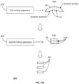
- FIG. 13C illustrates an example system 800", where the cylindrical blade 810" is configured to produce and hold a cylinder 52" of corneal tissue as the second cutting apparatus 820" makes a series of cuts to the corneal tissue cylinder 52".
- the second cutting apparatus 820" may be an ultraviolet femtosecond laser with a high numerical aperture (NA), e.g., greater than 0.8.
- NA numerical aperture
- the system 800" may include a source of hydration fluid 840, and the cylindrical blade 810" can be immersed in the source of hydration fluid 840 while holding the corneal tissue cylinder 52".
- the hydration fluid 840 keeps the corneal tissue cylinder 52" hydrated while the second cutting apparatus 820" cuts the portion of corneal tissue.
- the cylindrical blade 810" may include apertures or the like to allow the hydration fluid 840 into cylindrical blade 810" into contact with the corneal tissue cylinder 52".
- the temperature of the hydration fluid 840 can also be controlled to keep the corneal tissue cylinder 52" at a proper temperature.
- the system 800" may additionally include a cutting stage 850.
- the cylindrical blade 810" is configured to be mounted on the cutting stage 850 as the second cutting apparatus 820" makes the series of cuts to the corneal tissue cylinder 52".
- the cuts are made at least along the x-y plane as shown in FIG. 13C .
- a first end 810a" (e.g., bottom) of the cylindrical blade 810" is positioned on, or otherwise engaged by, the cutting stage 850, and the second cutting apparatus 820" is positioned to make the series of cuts at a second opposing end 810b" of (e.g., above) the cylindrical blade 810".
- the system 800" may include a guide system 860 that determines the position of the corneal tissue cylinder 52" for the second cutting apparatus 820".
- the guide system 840 may be an optical system that provides image or other data to a controller that can determine the position of the corneal tissue cylinder 52" from the data and control the operation of the second cutting apparatus 820".
- the cutting stage 830 may include an actuator 852, such as a piezoelectric actuator or similar electromechanical device, that contacts the corneal tissue cylinder 52" at the first end 810a" of the cylindrical blade 810" and moves (e.g., pushes) the corneal tissue cylinder 52" through the cylindrical blade 810" toward the second end 810b" as the second cutting apparatus 820" makes the series of cuts to the corneal tissue cylinder 52".
- an actuator 852 such as a piezoelectric actuator or similar electromechanical device
- Consecutive cuts made by the second cutting apparatus 820" include a first cut made closest to the anterior surface of the donor cornea 50 and a second cut made closest to the posterior surface of the donor cornea 50.
- the consecutive cuts form a corresponding lenticule 60 that includes a first surface formed by the first cut and a second surface formed by the second cut.
- the second cutting apparatus 820" may also shape at least one of the first surface or the second surface of the corresponding lenticule 60 to form the corneal implant with a desired refractive profile.
- the ultraviolet femtosecond laser can shape (e.g., sculpt) the most anterior (e.g., top) surface of the corneal tissue cylinder 52" along the x-, y-, z-axes according to a desired refractive profile.
- the laser spot of the ultraviolet femtosecond laser may be kept fixed in space and the cutting stage 850 may be operated to move along the x-, y-, z-axes relative to the laser spot.
- the laser of the ultraviolet femtosecond laser scans the corneal tissue cylinder 52" along the x-, y- , z-axes.
- the first surface of a lenticule 60 is formed when the most anterior surface is shaped.
- the ultraviolet femtosecond laser then makes a second cut to form the second surface of the lenticule 60 and release the lenticule 60 from the corneal tissue cylinder 52".
- the second surface may be planar or contoured (e.g., concave).
- the lenticule 60 may have any size or shape according to the desired refractive profile.
- the actuator 852 can move the corneal tissue cylinder 52" toward the second end 510b" (e.g., upwardly) and push the lenticule 60 out of the cylindrical blade 510".
- the system 800" may also include a robotic arm 870 that retrieves each lenticule 60 as it is formed by the second cutting apparatus 810 and pushed out of the cylindrical blade 510" by the actuator 852.
- the robotic arm 870 may apply a negative pressure to the lenticule 60 to hold the lenticule 60 by suction.
- the robotic arm 870 may transport the lenticule 60 for further processing, such as measurement and/or packaging.
- the system 800 may demonstrate how the second cutting apparatus 820 can cut the portion 52 of corneal tissue held by the first cutting apparatus 810.
- a cylindrical blade can hold the portion 52 of corneal tissue and a ultraviolet femtosecond laser can make a series of cuts starting from the most posterior surface of the portion 52 of corneal tissue and proceeding toward the most anterior surface (e.g., working from bottom to top).
- a ultraviolet femtosecond laser can make a series of cuts starting from the most posterior surface of the portion 52 of corneal tissue and proceeding toward the most anterior surface (e.g., working from bottom to top).
- Such an approach may produce meniscus-shaped lenses in particular, but other shapes are possible.
- the portion 52 of corneal tissue can be pushed through the cylindrical blade to produce a "pile" of lenticules 60.
- FIG. 10 illustrates an example approach 700 for shaping a lenticule to achieve a desired corneal implant.
- Laminar sheets may be cut from donor tissue 50 as described above.
- a delaminating cutting apparatus 710 includes a light source 712 that generates radiation for dissecting tissue 50a of the donor cornea 50 via photodisruption, photothermal cavitation, laser spallation, etc.
- the cutting apparatus 710 also includes an optical system 714 that can focus the radiation on the tissue 50a and cut the cornea 50 at a desired depth d below the anterior surface 50b of the cornea 50.
- the cutting apparatus 710 may generate a femtosecond laser to cut the cornea 50.
- lenticules 60 are then cut from the laminar sheets with varying sizes. For instance, from a laminar sheet 70a, two lenticules 60a are cut with a size that can be used to form implants 10a for treating presbyopia, and one lenticule 60b is cut with a size that can be used to form implants 10b for treating hyperopia. If three laminar sheets 70a can be cut from the donor cornea 50, six presbyopia lenticules 60a and three hyperopia lenticules 60b can be obtained from the cornea 50. Additionally or alternatively, from a laminar sheet 70b, six presbyopia lenticules 60a are cut, and with three such laminar sheets 70b, eighteen presbyopia lenticules 60a can be obtained from the cornea 50.
- a holding system 730 mechanically positions a lenticule 60 to receive shaping (e.g., ablative) radiation from an implant shaping apparatus 740.
- the holding system 730 includes a lower structure 732 and an upper structure 734.
- the lower structure 732 has a round (e.g., circular) upper surface 732a that receives the lenticule 60.
- the upper structure 734 has a rectangular lower surface 734a that holds (e.g., fixes) the lenticule 60 in position on the lower structure 732.
- the rectangular shape allows the upper structure 734 to engage the lenticule 60.
- the width (e.g., diameter) of the upper surface 732a of the lower structure 732 may be substantially equal to an edge length of the lower surface 734a of the upper structure 734.
- the lower structure 732 includes a round (e.g., circular) aperture 732b and the upper structure 734 includes a corresponding round (e.g., circular) aperture 734b.
- the apertures 732b, 734b allow the implant shaping apparatus 740 to shape the lenticule 60 between the lower structure 732 and the upper structure 734.
- a lenticule may be prepared and packaged (e.g., by a supplier) for delivery and subsequent reshaping (e.g., by a practitioner) at or near the time of actual implantation into the cornea.
- the lenticule may provide a more general shape (e.g., a blank) that can be subsequently reshaped into an implant according to any specific shape.
- the specific shape may cause a change in refractive power when implanted.
- the shape may include desired edge characteristics and other features that allow the structure of the implant to blend or transition smoothly into the surrounding eye structure, for instance, to improve optics and/or promote epithelial growth over the implant.
- a separate supplier packages and delivers a lenticule as a blank to a practitioner, the practitioner may need to know the starting measurements of the lenticule so that the proper amount of tissue can be accurately removed from the lenticule to obtain a precisely shaped corneal implant.
- the supplier may take the measurements of the lenticule prior to packaging and may provide the measurements to the practitioner.
- the supplier may provide instructions that the practitioner can follow to reshape the lenticule in order to obtain a particular shape for the implant. For instance, the instructions may indicate what tissue should be removed from particular locations of the lenticule. Such instructions are based on the measurements taken of the lenticule.
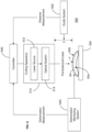
- FIG. 9 illustrates an example reshaping system 600 that allows a lenticule 60 to be reshaped in a controlled environment.
- the reshaping system 600 includes a lenticule cutting apparatus 610.
- the cutting apparatus 610 may include a laser source 612 that emits a laser, such as an excimer laser, capable of cutting corneal tissue.
- the cutting apparatus 610 may also include one or more optical elements 614 that direct the laser from the laser source.
- Such optical elements 614 may include any combination of lenses, mirrors, filters, beam splitters, etc.
- the example reshaping system 600 includes a staging device 630 that stages the lenticule 60 for reshaping by the cutting apparatus 610, while keeping the lenticule 60 in a proper state (e.g., hydration, temperature, etc.).
- the staging device 630 includes a container 632.
- the container 632 includes a chamber 632a, an upper opening 632b, and a lower opening 632c.
- the staging device 630 also includes a cover 634 to cover the upper opening 632b via threaded engagement, friction fit, clamps, or the like.
- the staging device 630 includes a plunger 636 that passes through the lower opening 632c into the chamber 632a.
- the plunger 636 includes an upper end 636a and a lower end 636b.
- the upper end 636a is disposed in the chamber 632a while the lower end 636b is accessible outside the chamber 632a from the bottom of the container 632.
- Pressure applied against the lower end 636b causes the plunger 636 to move farther through the lower opening 632c and into the chamber 632a. In effect, this pressure raises the upper end 636a within the chamber 632a.
- the lower end 636b can be pulled away from the container 632 to retract the plunger 636 from the chamber 632a. In effect, this action lowers the upper end 636a within the chamber 632a.
- the plunger 636 can be manually operated. In other embodiments, the plunger 636 may be actuated by a machine, e.g., electro-mechanical device.
- the staging device 630 includes a holder 638 that is configured to hold the lenticule 60.
- the upper end 636a of the plunger 636 is configured to receive the holder 638.
- a supplier can pack the lenticule 60 in the holder 638 for delivery to the practitioner.
- holder 638 facilitates handling of the lenticule 60.
- the lenticule 60 is already properly oriented in the holder 632 (e.g., with the correct surface facing up) for subsequent reshaping with the cutting apparatus 610.
- the cover 634 is removed from the upper opening 632b and the holder 638 with the lenticule 60 is positioned on the upper end 636a of the plunger 636.
- the chamber 632a is then filled to a predetermined level with hydrating fluid, e.g., balanced salt solution (BSS) or other standardized salt solution, to maintain the lenticule 60 in a hydrated state.
- BSS balanced salt solution
- the plunger 636 is positioned so that the lenticule 60 is submerged in the hydrating fluid.
- a liquid-tight seal is provided around the plunger 636 at the lower opening 632c so that liquid can be contained in the chamber 632a without escaping through the lower opening 632c.
- the cover 634 is then secured over the upper opening 632b of the container 632. Accordingly, the container 634 provides an enclosure in which the lenticule 60 can be reshaped in a controlled environment by the cutting apparatus 610.
- the cover 634 includes a window 634a that allows the cutting apparatus 610 to direct a laser into the chamber 632a to cut the lenticule 60 while the holder 638 with the lenticule 60 is disposed on the upper end 636a of the plunger 636.
- the window 634d may be formed from quartz that allows transmission of ultraviolet light, e.g., light having a wavelength equal to approximately 193 nm.
- the cutting apparatus 610 when the cutting apparatus 610 is aligned with the container 632 to reshape the lenticule 60, pressure can be applied to the lower end 636b of the plunger 636 to raise the holder 638 on the upper end 636a within the chamber 632a.
- the container 632 also includes one or more stops 632d that stop the plunger 636 from advancing beyond a predetermined distance within the chamber 632a.
- the lenticule 60 moves above the predetermined level of hydrating fluid to allow the laser from the cutting apparatus 610 to act on the lenticule 60.
- the posterior surface of the lenticule 60 may remain in contact with the hydrating fluid to maintain hydration.
- the holder 638 may include an aperture 638a to promote contact between the lenticule 60 and the hydrating fluid.
- the plunger 636 abuts the stops 632d and the lenticule 60 is raised above the predetermined fluid level; from this position, the plunger 636 can be retracted to submerge the lenticule 60 in the hydrating fluid.
- the staging device 630 also includes an air supply 640 that can deliver filtered air into the chamber 632a. Once the lenticule 60 is above the predetermined level of hydrating fluid, the air supply 640 can blow filtered air toward the lenticule 60 to dry and clean the lenticule 60 sufficiently for the reshaping process. Furthermore, as the cutting apparatus 610 reshapes the lenticule 60, the air supply 640 can continue to blow the filtered air to remove any ablation plume. The air supply 640 can deliver the air toward the lenticule 60 while avoiding direct air flow which may cause dehydration. After the lenticule 60 is reshaped, the plunger 636 can be retracted to draw the lenticule 60 back into the hydrating fluid.
- the staging device 630 may also include a heating element 650 that can control the temperature of the hydrating fluid.
- the temperature of the hydrating fluid may be raised to 37°C, which maintains the lenticule 60 at physiological temperature and provides humidity within the enclosure of the chamber 632a.
- the heating element 650 may be a small resistive coil, e.g., formed from Nichrome, and the temperature may be controlled by a thermistor.
- the hydrating fluid may also maintain an isotonic state for the lenticule 60.
- the cornea does not maintain an isotonic thickness, as the corneal endothelial pumps are continually working to dehydrate the cornea slightly.
- the thickness of the corneal tissue in vivo may be a slightly smaller than what its thickness would be in an isotonic solution. Therefore, when cutting the lenticule 60, the reshaping system 600 may take into account that the implant 10 sculpted from the lenticule 60 may become thinner after it is implanted in the recipient eye.
- the reshaping system 600 provides an example of a system for forming a corneal implant, where a receptacle (e.g., container 632) receives a lenticule and maintains a state (e.g., hydration, temperature, etc.) of the lenticule.
- a receptacle e.g., container 632
- the receptacle provides a controlled environment for precise and predictable cutting by a cutting apparatus.
- the per-pulse cutting rate for a laser may be sensitive to hydration of the lenticule 60, so the lenticule 60 may need to be predictably hydrated for precise and accurate sculpting.
- the reshaping system 600 also includes a controller 660, which may be implemented with at least one processor, at least one data storage device, etc., as described further below.
- the controller 660 is configured to determine a sculpting plan for modifying a first shape of the lenticule 60 and achieving a second shape for the lenticule 60 to produce the implant 10 with the desired refractive profile.
- the controller 660 can control the cutting apparatus 610 to direct, via the one or more optical elements 614, the laser from the laser source 612 to sculpt the lenticule 60 according to the sculpting plan to produce the implant 10.
- a monitoring system (not shown) may be employed to guide the laser relative to the position of the lenticule 60.
- the lenticule 60 may be reshaped in relation to predicted corneal biomechanical changes based on the depth of the implant within the cornea. Additionally or alternatively, the lenticule 60 may be reshaped in relation to predicted epithelium changes based on the deformation of the anterior stroma.
- controllers may be implemented as a combination of hardware and software elements.
- the hardware aspects may include combinations of operatively coupled hardware components including microprocessors, logical circuitry, communication/networking ports, digital filters, memory, or logical circuitry.
- the controller may be adapted to perform operations specified by a computer-executable code, which may be stored on a computer readable medium.
- the controller may be a programmable processing device, such as an external conventional computer or an on-board field programmable gate array (FPGA) or digital signal processor (DSP), that executes software, or stored instructions.
- FPGA field programmable gate array
- DSP digital signal processor
- physical processors and/or machines employed by embodiments of the present disclosure for any processing or evaluation may include one or more networked or non-networked general purpose computer systems, microprocessors, field programmable gate arrays (FPGA's), digital signal processors (DSP's), micro-controllers, and the like, programmed according to the teachings of the exemplary embodiments of the present disclosure, as is appreciated by those skilled in the computer and software arts.
- the physical processors and/or machines may be externally networked with the image capture device(s), or may be integrated to reside within the image capture device.
- Appropriate software can be readily prepared by programmers of ordinary skill based on the teachings of the exemplary embodiments, as is appreciated by those skilled in the software art.
- the devices and subsystems of the exemplary embodiments can be implemented by the preparation of application-specific integrated circuits or by interconnecting an appropriate network of conventional component circuits, as is appreciated by those skilled in the electrical art(s).
- the exemplary embodiments are not limited to any specific combination of hardware circuitry and/or software.
- the exemplary embodiments of the present disclosure may include software for controlling the devices and subsystems of the exemplary embodiments, for driving the devices and subsystems of the exemplary embodiments, for enabling the devices and subsystems of the exemplary embodiments to interact with a human user, and the like.
- software can include, but is not limited to, device drivers, firmware, operating systems, development tools, applications software, and the like.
- Such computer readable media further can include the computer program product of an embodiment of the present disclosure for performing all or a portion (if processing is distributed) of the processing performed in implementations.
- Computer code devices of the exemplary embodiments of the present disclosure can include any suitable interpretable or executable code mechanism, including but not limited to scripts, interpretable programs, dynamic link libraries (DLLs), Java classes and applets, complete executable programs, and the like. Moreover, parts of the processing of the exemplary embodiments of the present disclosure can be distributed for better performance, reliability, cost, and the like.
- interpretable or executable code mechanism including but not limited to scripts, interpretable programs, dynamic link libraries (DLLs), Java classes and applets, complete executable programs, and the like.
- Computer-readable media may include, for example, a floppy disk, a flexible disk, hard disk, magnetic tape, any other suitable magnetic medium, a CD-ROM, CDRW, DVD, any other suitable optical medium, punch cards, paper tape, optical mark sheets, any other suitable physical medium with patterns of holes or other optically recognizable indicia, a RAM, a PROM, an EPROM, a FLASH-EPROM, any other suitable memory chip or cartridge, a carrier wave or any other suitable medium from which a computer can read.
- a floppy disk a flexible disk, hard disk, magnetic tape, any other suitable magnetic medium, a CD-ROM, CDRW, DVD, any other suitable optical medium, punch cards, paper tape, optical mark sheets, any other suitable physical medium with patterns of holes or other optically recognizable indicia, a RAM, a PROM, an EPROM, a FLASH-EPROM, any other suitable memory chip or cartridge, a carrier wave or any other suitable medium from which a computer can read.
Landscapes
- Health & Medical Sciences (AREA)
- Engineering & Computer Science (AREA)
- Biomedical Technology (AREA)
- Transplantation (AREA)
- Ophthalmology & Optometry (AREA)
- Vascular Medicine (AREA)
- Public Health (AREA)
- Heart & Thoracic Surgery (AREA)
- Veterinary Medicine (AREA)
- Life Sciences & Earth Sciences (AREA)
- Animal Behavior & Ethology (AREA)
- General Health & Medical Sciences (AREA)
- Oral & Maxillofacial Surgery (AREA)
- Cardiology (AREA)
- Physics & Mathematics (AREA)
- Optics & Photonics (AREA)
- Nuclear Medicine, Radiotherapy & Molecular Imaging (AREA)
- Surgery (AREA)
- Prostheses (AREA)
Applications Claiming Priority (6)
| Application Number | Priority Date | Filing Date | Title |
|---|---|---|---|
| US201662332287P | 2016-05-05 | 2016-05-05 | |
| US201662381952P | 2016-08-31 | 2016-08-31 | |
| US201662438212P | 2016-12-22 | 2016-12-22 | |
| US201762449114P | 2017-01-23 | 2017-01-23 | |
| PCT/US2017/031339 WO2017193019A1 (fr) | 2016-05-05 | 2017-05-05 | Systèmes d'implant cornéen et procédés |
| EP17793469.2A EP3451969B1 (fr) | 2016-05-05 | 2017-05-05 | Systèmes d'implant cornéen |
Related Parent Applications (1)
| Application Number | Title | Priority Date | Filing Date |
|---|---|---|---|
| EP17793469.2A Division EP3451969B1 (fr) | 2016-05-05 | 2017-05-05 | Systèmes d'implant cornéen |
Publications (2)
| Publication Number | Publication Date |
|---|---|
| EP4335419A2 true EP4335419A2 (fr) | 2024-03-13 |
| EP4335419A3 EP4335419A3 (fr) | 2024-04-03 |
Family
ID=60203335
Family Applications (2)
| Application Number | Title | Priority Date | Filing Date |
|---|---|---|---|
| EP23211000.7A Pending EP4335419A3 (fr) | 2016-05-05 | 2017-05-05 | Systèmes et procédés d'implant cornéen |
| EP17793469.2A Active EP3451969B1 (fr) | 2016-05-05 | 2017-05-05 | Systèmes d'implant cornéen |
Family Applications After (1)
| Application Number | Title | Priority Date | Filing Date |
|---|---|---|---|
| EP17793469.2A Active EP3451969B1 (fr) | 2016-05-05 | 2017-05-05 | Systèmes d'implant cornéen |
Country Status (3)
| Country | Link |
|---|---|
| US (1) | US20170319329A1 (fr) |
| EP (2) | EP4335419A3 (fr) |
| WO (1) | WO2017193019A1 (fr) |
Families Citing this family (6)
| Publication number | Priority date | Publication date | Assignee | Title |
|---|---|---|---|---|
| US10555805B2 (en) * | 2006-02-24 | 2020-02-11 | Rvo 2.0, Inc. | Anterior corneal shapes and methods of providing the shapes |
| FR3083978B1 (fr) | 2018-07-17 | 2023-12-08 | Univ Jean Monnet Saint Etienne | Dispositif de maintien d’un tissu corneen pour son traitement photonique |
| FR3099045B1 (fr) | 2019-07-22 | 2021-07-30 | Univ Jean Monnet Saint Etienne | Procede de production d’une pluralite d’implants a partir d’une cornee humaine ou animale prealablement prelevee |
| EP4125750B1 (fr) * | 2020-04-01 | 2025-05-07 | Carl Zeiss Meditec AG | Équipement de chirurgie réfractive, en particulier pour kératoplastie |
| US11759308B2 (en) * | 2021-07-24 | 2023-09-19 | Peter S. Hersh | Devices for the amelioration of an abnormality of a cornea and methods of using them |
| US11406531B1 (en) * | 2021-07-24 | 2022-08-09 | Peter S. Hersh | Method for the amelioration of ectatic and irregular corneal disorders |
Citations (3)
| Publication number | Priority date | Publication date | Assignee | Title |
|---|---|---|---|---|
| EP2371329A1 (fr) * | 2010-04-02 | 2011-10-05 | IVIS Tecnologie Medicali Srl, . | Procédé et appareil de préparation personnalisée de cornées de donneur pour implant lamellaire cornéen |
| US20140264980A1 (en) | 2013-03-14 | 2014-09-18 | David Muller | Corneal implant systems and methods |
| US20170027754A1 (en) | 2015-07-31 | 2017-02-02 | David Muller | Corneal implant systems and methods |
Family Cites Families (3)
| Publication number | Priority date | Publication date | Assignee | Title |
|---|---|---|---|---|
| FR2892962B1 (fr) * | 2005-11-04 | 2009-06-05 | Centre Nat Rech Scient | Microtome laser femtoseconde pour decoupe par faisceau laser d'une tranche de matiere, notamment dans une cornee |
| US8916207B2 (en) * | 2006-12-04 | 2014-12-23 | Body Organ Biomedical Corp. | Corneal cover or corneal implant and contact lens and method thereof |
| IN2014CN02153A (fr) * | 2011-08-23 | 2015-05-29 | Yeda Res & Dev |
-
2017
- 2017-05-05 WO PCT/US2017/031339 patent/WO2017193019A1/fr not_active Ceased
- 2017-05-05 EP EP23211000.7A patent/EP4335419A3/fr active Pending
- 2017-05-05 US US15/588,249 patent/US20170319329A1/en not_active Abandoned
- 2017-05-05 EP EP17793469.2A patent/EP3451969B1/fr active Active
Patent Citations (3)
| Publication number | Priority date | Publication date | Assignee | Title |
|---|---|---|---|---|
| EP2371329A1 (fr) * | 2010-04-02 | 2011-10-05 | IVIS Tecnologie Medicali Srl, . | Procédé et appareil de préparation personnalisée de cornées de donneur pour implant lamellaire cornéen |
| US20140264980A1 (en) | 2013-03-14 | 2014-09-18 | David Muller | Corneal implant systems and methods |
| US20170027754A1 (en) | 2015-07-31 | 2017-02-02 | David Muller | Corneal implant systems and methods |
Non-Patent Citations (1)
| Title |
|---|
| SMITH ET AL.: "Effect of defocus on on-axis wave aberration of a centered optical system", JOURNAL OF THE OPTICAL SOCIETY OF AMERICA A: OPTICS, IMAGE SCIENCE, AND VISION, vol. 23, no. 11, 2006, pages 2686 - 2689 |
Also Published As
| Publication number | Publication date |
|---|---|
| WO2017193019A1 (fr) | 2017-11-09 |
| EP4335419A3 (fr) | 2024-04-03 |
| EP3451969B1 (fr) | 2023-11-22 |
| US20170319329A1 (en) | 2017-11-09 |
| EP3451969A1 (fr) | 2019-03-13 |
| EP3451969A4 (fr) | 2019-11-27 |
Similar Documents
| Publication | Publication Date | Title |
|---|---|---|
| US12070422B2 (en) | Corneal implant systems and methods | |
| EP3451969B1 (fr) | Systèmes d'implant cornéen | |
| EP2967995B1 (fr) | Procédés d'implant cornéen | |
| AU2017203906B2 (en) | Method for laser cutting a corneal pocket | |
| US20030014042A1 (en) | Method of creating stromal pockets for corneal implants | |
| CN113692265B (zh) | 用于眼睛激光手术、特别用于角膜移植术的装置和方法 | |
| JP2007537829A (ja) | 視力強化のための角膜アンレー及び波面収差修正 | |
| EP2672926B1 (fr) | Restauration de l'accommodation par remplissage du cristallin | |
| CN107072816B (zh) | 眼外科手术方法 | |
| EP1138291A2 (fr) | Procédé de préparation d'un dispositif pour la chirurgie cornéenne | |
| US20090012506A1 (en) | Laser mask for creating a corneal pocket | |
| US10548771B2 (en) | Device and procedure to treat presbyopia | |
| HK1193557A (en) | Method for laser cutting a corneal pocket |
Legal Events
| Date | Code | Title | Description |
|---|---|---|---|
| PUAI | Public reference made under article 153(3) epc to a published international application that has entered the european phase |
Free format text: ORIGINAL CODE: 0009012 |
|
| STAA | Information on the status of an ep patent application or granted ep patent |
Free format text: STATUS: THE APPLICATION HAS BEEN PUBLISHED |
|
| REG | Reference to a national code |
Ref country code: DE Ref legal event code: R079 Free format text: PREVIOUS MAIN CLASS: A61F0009010000 Ipc: A61F0002140000 |
|
| PUAL | Search report despatched |
Free format text: ORIGINAL CODE: 0009013 |
|
| AC | Divisional application: reference to earlier application |
Ref document number: 3451969 Country of ref document: EP Kind code of ref document: P |
|
| AK | Designated contracting states |
Kind code of ref document: A2 Designated state(s): AL AT BE BG CH CY CZ DE DK EE ES FI FR GB GR HR HU IE IS IT LI LT LU LV MC MK MT NL NO PL PT RO RS SE SI SK SM TR |
|
| AK | Designated contracting states |
Kind code of ref document: A3 Designated state(s): AL AT BE BG CH CY CZ DE DK EE ES FI FR GB GR HR HU IE IS IT LI LT LU LV MC MK MT NL NO PL PT RO RS SE SI SK SM TR |
|
| RIC1 | Information provided on ipc code assigned before grant |
Ipc: A61F 9/01 20060101ALI20240227BHEP Ipc: A61F 2/14 20060101AFI20240227BHEP |
|
| STAA | Information on the status of an ep patent application or granted ep patent |
Free format text: STATUS: REQUEST FOR EXAMINATION WAS MADE |
|
| 17P | Request for examination filed |
Effective date: 20241003 |
|
| RBV | Designated contracting states (corrected) |
Designated state(s): AL AT BE BG CH CY CZ DE DK EE ES FI FR GB GR HR HU IE IS IT LI LT LU LV MC MK MT NL NO PL PT RO RS SE SI SK SM TR |
|
| GRAP | Despatch of communication of intention to grant a patent |
Free format text: ORIGINAL CODE: EPIDOSNIGR1 |
|
| STAA | Information on the status of an ep patent application or granted ep patent |
Free format text: STATUS: GRANT OF PATENT IS INTENDED |
|
| RIC1 | Information provided on ipc code assigned before grant |
Ipc: A61F 2/14 20060101AFI20260227BHEP Ipc: A61F 9/01 20060101ALI20260227BHEP |
|
| INTG | Intention to grant announced |
Effective date: 20260327 |