EP4335423B1 - Fauteuil roulant électrique tout terrain et ensemble correspondant - Google Patents
Fauteuil roulant électrique tout terrain et ensemble correspondant Download PDFInfo
- Publication number
- EP4335423B1 EP4335423B1 EP23195758.0A EP23195758A EP4335423B1 EP 4335423 B1 EP4335423 B1 EP 4335423B1 EP 23195758 A EP23195758 A EP 23195758A EP 4335423 B1 EP4335423 B1 EP 4335423B1
- Authority
- EP
- European Patent Office
- Prior art keywords
- subassembly
- wheelchair assembly
- assembly
- motor
- wheelchair
- Prior art date
- Legal status (The legal status is an assumption and is not a legal conclusion. Google has not performed a legal analysis and makes no representation as to the accuracy of the status listed.)
- Active
Links
Images








Classifications
-
- A—HUMAN NECESSITIES
- A61—MEDICAL OR VETERINARY SCIENCE; HYGIENE
- A61G—TRANSPORT, PERSONAL CONVEYANCES, OR ACCOMMODATION SPECIALLY ADAPTED FOR PATIENTS OR DISABLED PERSONS; OPERATING TABLES OR CHAIRS; CHAIRS FOR DENTISTRY; FUNERAL DEVICES
- A61G5/00—Chairs or personal conveyances specially adapted for patients or disabled persons, e.g. wheelchairs
- A61G5/06—Chairs or personal conveyances specially adapted for patients or disabled persons, e.g. wheelchairs with obstacle mounting facilities, e.g. for climbing stairs, kerbs or steps
-
- A—HUMAN NECESSITIES
- A61—MEDICAL OR VETERINARY SCIENCE; HYGIENE
- A61G—TRANSPORT, PERSONAL CONVEYANCES, OR ACCOMMODATION SPECIALLY ADAPTED FOR PATIENTS OR DISABLED PERSONS; OPERATING TABLES OR CHAIRS; CHAIRS FOR DENTISTRY; FUNERAL DEVICES
- A61G5/00—Chairs or personal conveyances specially adapted for patients or disabled persons, e.g. wheelchairs
- A61G5/04—Chairs or personal conveyances specially adapted for patients or disabled persons, e.g. wheelchairs motor-driven
- A61G5/047—Chairs or personal conveyances specially adapted for patients or disabled persons, e.g. wheelchairs motor-driven by a modular detachable drive system
-
- A—HUMAN NECESSITIES
- A61—MEDICAL OR VETERINARY SCIENCE; HYGIENE
- A61G—TRANSPORT, PERSONAL CONVEYANCES, OR ACCOMMODATION SPECIALLY ADAPTED FOR PATIENTS OR DISABLED PERSONS; OPERATING TABLES OR CHAIRS; CHAIRS FOR DENTISTRY; FUNERAL DEVICES
- A61G5/00—Chairs or personal conveyances specially adapted for patients or disabled persons, e.g. wheelchairs
- A61G5/04—Chairs or personal conveyances specially adapted for patients or disabled persons, e.g. wheelchairs motor-driven
- A61G5/041—Chairs or personal conveyances specially adapted for patients or disabled persons, e.g. wheelchairs motor-driven having a specific drive-type
-
- A—HUMAN NECESSITIES
- A61—MEDICAL OR VETERINARY SCIENCE; HYGIENE
- A61G—TRANSPORT, PERSONAL CONVEYANCES, OR ACCOMMODATION SPECIALLY ADAPTED FOR PATIENTS OR DISABLED PERSONS; OPERATING TABLES OR CHAIRS; CHAIRS FOR DENTISTRY; FUNERAL DEVICES
- A61G5/00—Chairs or personal conveyances specially adapted for patients or disabled persons, e.g. wheelchairs
- A61G5/08—Chairs or personal conveyances specially adapted for patients or disabled persons, e.g. wheelchairs foldable
- A61G5/0875—Chairs or personal conveyances specially adapted for patients or disabled persons, e.g. wheelchairs foldable dismountable, e.g. where the wheelchair can be disassembled for transportation or storage
-
- A—HUMAN NECESSITIES
- A61—MEDICAL OR VETERINARY SCIENCE; HYGIENE
- A61G—TRANSPORT, PERSONAL CONVEYANCES, OR ACCOMMODATION SPECIALLY ADAPTED FOR PATIENTS OR DISABLED PERSONS; OPERATING TABLES OR CHAIRS; CHAIRS FOR DENTISTRY; FUNERAL DEVICES
- A61G5/00—Chairs or personal conveyances specially adapted for patients or disabled persons, e.g. wheelchairs
- A61G5/10—Parts, details or accessories
-
- A—HUMAN NECESSITIES
- A61—MEDICAL OR VETERINARY SCIENCE; HYGIENE
- A61G—TRANSPORT, PERSONAL CONVEYANCES, OR ACCOMMODATION SPECIALLY ADAPTED FOR PATIENTS OR DISABLED PERSONS; OPERATING TABLES OR CHAIRS; CHAIRS FOR DENTISTRY; FUNERAL DEVICES
- A61G5/00—Chairs or personal conveyances specially adapted for patients or disabled persons, e.g. wheelchairs
- A61G5/10—Parts, details or accessories
- A61G5/1056—Arrangements for adjusting the seat
- A61G5/1067—Arrangements for adjusting the seat adjusting the backrest relative to the seat portion
-
- A—HUMAN NECESSITIES
- A61—MEDICAL OR VETERINARY SCIENCE; HYGIENE
- A61G—TRANSPORT, PERSONAL CONVEYANCES, OR ACCOMMODATION SPECIALLY ADAPTED FOR PATIENTS OR DISABLED PERSONS; OPERATING TABLES OR CHAIRS; CHAIRS FOR DENTISTRY; FUNERAL DEVICES
- A61G5/00—Chairs or personal conveyances specially adapted for patients or disabled persons, e.g. wheelchairs
- A61G5/10—Parts, details or accessories
- A61G5/1083—Quickly-removable wheels
-
- A—HUMAN NECESSITIES
- A61—MEDICAL OR VETERINARY SCIENCE; HYGIENE
- A61G—TRANSPORT, PERSONAL CONVEYANCES, OR ACCOMMODATION SPECIALLY ADAPTED FOR PATIENTS OR DISABLED PERSONS; OPERATING TABLES OR CHAIRS; CHAIRS FOR DENTISTRY; FUNERAL DEVICES
- A61G5/00—Chairs or personal conveyances specially adapted for patients or disabled persons, e.g. wheelchairs
- A61G5/10—Parts, details or accessories
- A61G5/1089—Anti-tip devices
-
- A—HUMAN NECESSITIES
- A61—MEDICAL OR VETERINARY SCIENCE; HYGIENE
- A61G—TRANSPORT, PERSONAL CONVEYANCES, OR ACCOMMODATION SPECIALLY ADAPTED FOR PATIENTS OR DISABLED PERSONS; OPERATING TABLES OR CHAIRS; CHAIRS FOR DENTISTRY; FUNERAL DEVICES
- A61G5/00—Chairs or personal conveyances specially adapted for patients or disabled persons, e.g. wheelchairs
- A61G5/10—Parts, details or accessories
- A61G5/12—Rests specially adapted therefor, e.g. for the head or the feet
- A61G5/125—Rests specially adapted therefor, e.g. for the head or the feet for arms
Definitions
- Embodiments of the present invention relate generally to an improved wheelchair and, more particularly, an all-terrain electric wheelchair that is easy to assemble, disassemble, store, and transport.
- All-terrain wheelchairs are used to help people with mobility issues traverse across all-types of terrain.
- beaches are particularly difficult to traverse due to, for example, soft sand, dunes, rocky terrain, etc.
- Beach wheelchairs are most often manually propelled, although there are some electrically powered beach wheelchairs.
- these electrically powered beach wheelchairs are often very large, heavy, expensive, and difficult to transport. These issues discourage or prevent many individuals from being able to regularly use electrically powered beach wheelchairs. These issues also tend to discourage individuals from purchasing their own electrically powered beach wheelchairs.
- EP 1 523 970 A1 discloses a powered vehicle for personal mobility comprising first and second frame parts.
- Various embodiments described herein enable users to disassemble the wheelchair assembly to smaller components that are easier to carry, store, and transport.
- Some of the heaviest components in the wheelchair assembly may be electrical components such as the battery and the components associated with the motor. These components often possess an increased weight, which may be problematic or less desirable for all-terrain wheelchair assemblies that may require greater power to operate over different types of terrain.
- Various embodiments account for this by providing motor components on a separate motor subassembly that can be selectively attached or disengaged from the remainder of the wheelchair assembly, and the battery may be provided separately and mountable to a seat subassembly that is separate from the motor subassembly.
- the overall weight of the motor subassembly may be greatly reduced and the overall weight of the seat subassembly (including the battery) may still be relatively light.
- the battery may be further separated from the seat subassembly to further reduce weight of each carriable part (e.g., each subassembly).
- the motor subassembly and the seat subassembly may both be easily carriable by a single person when carried separately.
- the weight distribution of the wheelchair assembly as a whole may be improved.
- the subassemblies may be permitted to fit into smaller storage areas.
- the wheelchair assembly may be assembled, disassembled, and stored without the requirement of vans, trailers, specialist lifts, or ramps, increasing its ease of use.
- SUV sports utility vehicle
- the motor subassembly may also be selectively added or removed from the seat subassembly, and this may give the user an option to remove the motor subassembly so that the seat subassembly is used by manually moving the seat subassembly.
- the motor subassembly may be designed in a manner that is easily retrofittable to existing wheelchairs or seat subassemblies.
- an occupant is intended to refer to a person sitting in the wheelchair assembly
- an assistant is intended to refer to a person other than the occupant that is assisting in moving, assembling, disassembling, storing, transporting, etc. the wheelchair assembly.
- a user is intended to refer to either the occupant or an assistant.
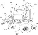
- FIG. 1 illustrates a perspective view of an example wheelchair assembly 100.
- the wheelchair assembly 100 may include various frames.
- the wheelchair assembly 100 has a seat frame 106, a backrest frame 108, and a footrest frame 110.
- the backrest frame 108 may include rear handles 112 where an assistant may grasp the rear handles 112 to push the wheelchair assembly 100.
- the backrest frame 108 may include occupant armrests 114. These occupant armrests 114 may provide armrests for the occupant to rest their arms.
- the occupant armrests 114 may be pivotable in the wheelchair assembly 100. This may be beneficial to permit occupants to more easily exit the wheelchair assembly 100. Furthermore, the pivotable nature of occupant armrests 114 may make the backrest frame 108 more compact when stored.
- upholstery 124 may be provided on the various frames and components of the wheelchair assembly 100 to increase the comfort level for users.
- the upholstery in some embodiments, may be designed for use with sandy environments, such as beaches (e.g., the upholstery may be easily washable).
- Wheelchair assemblies may include various wheels.
- the wheelchair assembly 100 may include front wheels 116, driven wheels 118, and anti-tip wheels 120.
- the driven wheels 118 may require driven wheels 118 that are large in order for the wheels to effectively move in difficult terrains.
- the driven wheels 118 possess a diameter of forty-nine (49) centimeters and a width of twenty-three (23) centimeters, but driven wheels 118 of other sizes may be used.
- Rotation of the driven wheels 118 may be generated by a motors 240 (see FIG. 2C ) and the electrical components in the wheelchair assembly 100.
- the front wheels 116 and the anti-tip wheels 120 are not electrically powered, and these wheels are permitted to adjust in angular orientation and rotational speed based on adjustments at the driven wheels 118.
- the front wheels 116 are caster wheels so that the orientation of the wheels can be easily adjusted as necessary based on the movement of the driven wheels 118.
- the front wheels 116 are thirty (30) centimeters in diameter and eighteen (18) centimeters in width, but other dimensions may be used for the front wheels 116 in other embodiments.
- the present disclosure describes the main rear wheels (driven wheels 118) as driven wheels, depending on the configuration, any of the wheels may be "driven" by one or more motors.
- the front wheels 116 and the anti-tip wheels 120 may be electrically powered in other embodiments.
- driven wheels 118 may be driven at different rates, and this may be beneficial to allow the wheelchair assembly 100 to easily rotate towards the left or to the right.
- the anti-tip wheels 120 may be elevated slightly above the ground so that the anti-tip wheels 120 will not contact the ground when the wheelchair assembly 100 is oriented in a typical upright manner. Further, the anti-tip wheels 120 may come in contact with the ground only when the wheelchair assembly 100 is rotated backward (e.g. clockwise in FIG. 1 ). In this way, the anti-tip wheels 120 may prevent the wheelchair assembly 100 from tipping backward. However, in other embodiments, the anti-tip wheels 120 may be configured to contact the ground even when the wheelchair assembly 100 is in a typical upright orientation. The anti-tip wheels 120 may be beneficial to prevent the motors 240 ( see FIG. 2C ) from coming in contact with the ground - if the wheelchair assembly 100 begins to tip backward, the anti-tip wheels 120 may come in contact with the ground before the motors 240 ( see FIG. 2C ).
- an input device 126 is provided at the end of an occupant armrest 114.
- the input device 126 may be provided at other locations such as at the rear handle 112, on the side of a seat frame 106, on the back of the backrest frame 108, on the motor subassembly 204 ( see FIG. 2A ), etc.
- the input device 126 may be used to provide inputs to control the operation of the wheelchair assembly 100.
- the input device 126 may be connected to other electrical systems in the wheelchair assembly 100 so that inputs provided at the input device 126 may be executed by the electrical systems.
- the input device 126 may be configured to receive user commands regarding the user's desired speed or direction for the wheelchair assembly 100, and, based on the inputs received at the input device 126, the operation of the motors 240 ( see FIG. 2C ) may be adjusted to change the speed of the driven wheels 118 or the direction of the wheelchair assembly 100.
- the direction of the wheelchair assembly 100 may, for example, be changed by rotating the driven wheels 118 at different rotational speeds.
- the input device 126 includes a joystick 128 to receive user commands, however directional buttons and other components may be provided on the input device 126 as an additional or alternative way of inputting commands.
- the input device 126 may be configured to receive various commands - for example, the input device 126 may receive commands to operate in manual mode or electrically powered mode, to adjust maximum or minimum speeds, etc.
- the input device 126 may be part of an electronic control assembly that is configured to control motion of the wheelchair assembly 100.
- the wheelchair assembly 100 is an all-terrain wheelchair assembly.
- the front wheels 116, the driven wheels 118, and/or the anti-tip wheels 120 may be balloon tires, and the balloon tires may be configured to more easily traverse difficult terrains such as soft sand, hard sand, stony terrains, muddy terrains, and rocky terrains.
- each of the front wheels 116, the driven wheels 118, and the anti-tip wheels 120 are balloon tires, whereas, in the illustrated embodiment of FIG. 2A , only the front wheels 116 and the driven wheels 118 are balloon tires.
- FIG. 1 each of the front wheels 116, the driven wheels 118, and the anti-tip wheels 120 are balloon tires, whereas, in the illustrated embodiment of FIG. 2A , only the front wheels 116 and the driven wheels 118 are balloon tires.
- FIG. 2A only the front wheels 116 and the driven wheels 118 are balloon tires.
- the anti-tip wheels 220A are firm (e.g., traditional) wheels to aid in "digging” in to sand for increased traction.
- the balloon tires may be low-pressure balloon tires that are large, soft, and pliable in some embodiments, and these balloon tires may tend to float over sand compared to traditional wheels.
- a significant portion of the weight of the wheelchair assembly 100 may rest on the driven wheels 118, and this may be beneficial to ensure that the driven wheels 118 have traction to drive the wheelchair assembly 100.
- Balloon tires may greatly reduce the forces required to move the wheelchair assembly 100 across soft sand and other difficult terrains. Other traditional wheelchair assemblies often struggle to traverse soft sand and other difficult terrains and tend to get stuck in these difficult terrains.
- the wheelchair assembly 100 enables occupants to reach a larger number of areas as compared to more traditional wheelchair assembles.
- FIG. 1 illustrates one example wheelchair assembly
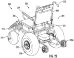
- FIG. 2A-2B illustrate varying perspective views of another example wheelchair assembly 200.
- the wheelchair assembly 200 may include a seat subassembly 202 and a motor subassembly 204.
- the wheelchair assembly 200 is configured to be easily assembled and disassembled, and the seat subassembly 202 and the motor subassembly 204 are configured to be selectively attached with each other to form the wheelchair assembly 200.
- Different subassemblies within the wheelchair assembly 200 are selectively assembled and disassembled using toggle pins in the subassemblies. However, attachment of the subassemblies may be accomplished using other fasteners.
- the seat subassembly 202 and the motor subassembly 204 are configured to be disassembled from each other so that they can be separately moved and carried by a single person. Once the subassemblies are disassembled, a user may easily move the seat subassembly 202 by resting the weight of the seat subassembly 202 on the front wheels 216, and the user may easily move the motor subassembly 204 by resting the weight of the motor subassembly 204 on the driven wheels 218. With the weight of the relevant subassembly on its wheels, the subassembly may be easily shifted and a reciprocal rotation of the wheels may be caused.
- the user may be required to disengage a gearbox 442 (see FIG. 4B ) in order to permit the driven wheels 218 to be freely rotated.
- Disassembly of the seat subassembly 202 and the motor subassembly 204 may permit these subassemblies to be fit into smaller volumes.
- the two subassemblies may be stored together in a volume of less than 70 cubic feet, less than 50 cubic feet, less than 40 cubic feet, less than 30 cubic feet, or preferably less than 20 cubic feet.
- the subassemblies may be configured to fit in the trunk or boot of a vehicle such as an SUV.
- the seat subassembly 202 may include the seat frame 206, the backrest frame 208, and the footrest frame 210, and upholstery 224 (which may be provided on each of these frames to increase the comfort level for users).
- the backrest frame 208 may include rear handles 212 where an assistant may grasp the rear handles 212 to push the wheelchair assembly 200.
- the backrest frame 208 may include occupant armrests 214. These occupant armrests 214 may provide armrests for the occupant to rest his or her arms.
- the occupant armrests 214 are pivotable in the wheelchair assembly 200. This may be beneficial to permit occupants to more easily exit the wheelchair assembly 200.
- the pivotable nature of the occupant armrests 214 may make the backrest frame 208 more compact when stored. However, the occupant armrests may not be pivotable in other embodiments.
- wheelchair assemblies may include various wheels.
- the wheelchair assembly 200 may include front wheels 216, driven wheels 218, and anti-tip wheels 220A.
- the illustrated anti-tip wheels 220A may not be balloon tires (and, instead, be traditional wheels).
- the driven wheels 218 may require balloon tires that are large in order for the wheels to effectively move in difficult terrains.
- the driven wheels 218 may possess a diameter of forty-nine (49) centimeters and a width of twenty-three (23) centimeters, but other sized driven wheels 218 may also be used. Rotation of the driven wheels 218 may be generated by motors 240 ( see FIG. 2C ) and the electrical components in the wheelchair assembly 200.
- the front wheels 216 and the anti-tip wheels 220A are not electrically powered and are permitted to adjust angular orientation and rotation speed based on adjustments at the driven wheels 218.
- the front wheels 216 are caster wheels so that the orientation of the wheels can be easily adjusted as necessary based on the movement of the driven wheels 218.
- the front wheels 216 and the anti-tip wheels 220A may be electrically powered in other embodiments.
- the wheelchair assembly may be an all-terrain wheelchair assembly.
- the wheelchair assembly may be configured to be used in more difficult environments such as beaches, which may have soft sand, dunes, and rocky terrain that is difficult to traverse.
- the front wheels 216 and the driven wheels 218 may each be balloon tires that are configured to more easily traverse difficult terrains such as soft sand, hard sand, stony terrains, muddy terrains, and rocky terrains.
- the all-terrain nature of the wheelchair assembly 200 may require power where the wheelchair assembly 200 is electrically powered.
- traversing over sand may require more power than other surfaces in urban environments such as pavement or hard floors.
- the electrically powered wheelchair assembly 200 may require larger motors and higher battery capacity.
- the motor 240 and the battery 730' see FIG. 7 ) may be some of the heavier components in the wheelchair assembly 200.
- a battery box 230 may be provided in the seat subassembly 202. More particularly, the battery box 230 is installed at the seat frame 206 underneath the location where the occupant sits.
- a battery 730' (see FIG. 7 ) may be provided within the battery box 230, and the battery 730' may have a weight of approximately fifteen (15) kilograms (although other weights are contemplated, such as less than 16 kilograms, less than 15.5 kilograms, less than 15 kilograms, etc.). Placement of the battery box 230 at the seat subassembly 202 may also tend to improve the weight distribution of the wheelchair assembly 200 as a whole by separating the heavier battery box 230 and the heavier components associated with the motor(s) 240 from each other (see e.g., FIG. 2C ). Furthermore, the weight of the battery 730' may be reduced by using lithium style batteries rather than traditional lead acid batteries. Notably, any type of battery may be used with various example embodiments described herein.
- the wheelchair assembly 200 may define a front-to-back direction, and the wheelchair assembly 200 may define a center of gravity.
- the motor subassembly 204 and the battery box 230 may each define a center of gravity.
- the center of gravity for the motor subassembly 204 may be provided rearwardly of the center of gravity for the wheelchair assembly 200 along the front-to-back direction.
- the center of gravity for the battery 230 may be provided in front of the center of gravity for the wheelchair assembly 200 along the front-to-back direction.
- the battery and the motors are separated by a horizontal distance of at least two hundred five (205) millimeters when the wheelchair assembly 200 is fully assembled and oriented in an upright position, and this may improve the weight distribution of the wheelchair assembly 200. Improved weight distribution may be particularly important when the wheelchair assembly 200 is operating on an incline, as the incline may alter the typical orientation of the wheelchair assembly 200.
- the weight of the motor subassembly 204 may be reduced.
- the weight of the seat subassembly 202 may be less than thirty-five (35) kilograms
- the weight of the motor subassembly 204 may be less than twenty-nine (29) kilograms.
- the wheelchair assembly 200 may be disassembled so that the seat subassembly 202 and the motor subassembly 204 are separated from each other, and each subassembly may be moved, carried or lifted individually by a single person.
- a single person may still easily move the subassemblies to a storage location (e.g. a vehicle trunk or boot) and then the subassemblies may be easily carried or lifted into the storage location by two people.
- a storage location e.g. a vehicle trunk or boot
- the seat subassembly 202 and/or the motor subassembly 204 may be further broken down into easily attachable or mountable parts that further reduce weight of carriable parts.
- the seat subassembly 202 may be broken down into a battery subassembly (that may be positionable within the battery box 230), one or more front wheel assemblies (that each may be attachable to seat frame), a battery box subassembly, a backrest subassembly (that may include the backrest frame 208), and/or other subassemblies.
- the motor subassembly 204 may be broken down into a motor platform subassembly, one or more anti-tip wheel subassemblies, one or more driven wheel assemblies, and/or other subassemblies.
- each subassembly may be easily carriable and attachable to each other to form the wheelchair assembly. In some embodiments, each subassembly may be less than thirty-five (35) kilograms.
- connection arm 221 may help facilitate the connection between the motor subassembly 204 and the seat subassembly 202.
- the user may remove the motor subassembly 204 and the connection arm 221.
- a rear axle 621A ( see FIG. 6D ) may be installed in place of the connection arm 221, and rear wheels 618' ( see FIG. 6D ) similar to the driven wheels 218 may be connected at both ends of the rear axle 621A.
- FIG. 2C illustrates an enhanced perspective view of the example motor subassembly 204 where components within the motor subassembly 204 may be more easily seen.
- One or more motors 240 may be provided in order to generate rotation of the driven wheel hubs 218A and the driven wheels 218 that are attached to these driven wheel hubs 218A.
- two motors 240 are provided, and each motor 240 is provided adjacent to a respective driven wheel 218 and is configured to generate rotation of the respective driven wheel 218.
- Additional motors may be provided in other embodiments, and motors may be used at other locations.
- motors may be used to generate rotation of the front wheels or the anti-tip wheels, and the motors may be positioned adjacent to these wheels.
- Axles 222 may extend from a gearbox 442 ( see FIG. 4B ) and may engage with the driven wheels 218.
- the motor subassembly 204 may include a motor platform 236.
- the motor platform 236 may provide a location where a top portion 238A of a motor controller box and a bottom portion 238B of a motor controller box may be attached.
- a motor controller may be provided in the motor controller box to control the operation of the motors 240.
- Electrical wiring may extend from the motor controller to the battery box 230 ( see FIG. 3A ), to the input device 126 ( see FIG. 1 ), and to other electrical components.
- Motors 240 may be installed on the underside of the motor platform 236.
- Positioning the motors 240 at this location may help prevent water or other materials projected from the front wheels 216 from coming into contact with the motors 240, and the motors 240 may be provided proximate to the driven wheels 218 so provide a smaller footprint for the motor subassembly 204.
- the motor platform 236 may include arms 232 extending upwardly to connect with the backrest frame 208.
- the arms 232 may be connected to mounting lugs 236A provided on the motor platform 236.
- the arms 232 may be pivotable about an axis defined at the mounting lugs 236A ( see FIG. 4C ) so that the overall volume of the motor subassembly 204 may be reduced when the motor subassembly 204 is disassembled from the seat subassembly 202 ( see FIG. 2A ).
- the motor platform 236 may be connected to the connection arm 221 using one or more fasteners.
- anti-tip wheels 220A may be provided in the motor subassembly 204. Arms 234 may extend rearwardly from the motor platform 236, and the anti-tip wheels 220A may be connected to the arms 234.
- FIGS. 3A-3C illustrate varying perspective views of an example seat subassembly 202.
- the seat subassembly 202 may include the seat frame 206, the backrest frame 208, and the footrest frame 210.
- the seat subassembly 202 may connect to a connection arm 221 ( see FIG. 2C ) that is provided in the motor subassembly 204 ( see FIG. 2C ).
- the connection arm 221 may help facilitate a connection between the seat subassembly 202 and the motor subassembly 204 ( see FIG. 2C ).
- the user may remove the motor subassembly 204 and connect a rear axle 621A ( see FIG. 6D ) in place of the connection arm 221, and rear wheels 618' ( see FIG. 6D ) similar to the driven wheels 218 may be installed at both ends of the rear axle 621A using fasteners.
- a user may wish to operate the wheelchair assembly 200 proximate to water - where this is the case, the user may remove the motor subassembly 204 and other electronic components such as the input device 126 ( see FIG. 1 ) and the battery box 230 to avoid exposure of these electrical components to the water.
- electrical components may be protected with waterproof seals in some embodiments.
- connection arm 221 may possess features that help to position the seat subassembly 202 correctly relative to the motor subassembly 204 ( see FIG. 2C ).
- protrusions 421B see FIG. 4B
- holes may be provided in the connection arm 221, in the seat subassembly 202, and at the motor subassembly 204 to help facilitate the connection between the two subassemblies.
- FIGS. 3A-3C illustrate a seat subassembly 202
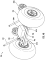
- FIGS. 4A-4B illustrate varying perspective views of an example motor subassembly 204 that may be attached to the seat subassembly 202
- the motor subassembly 204 may include motors 240 and gearboxes 442 associated with motors 240.
- a rear axle 222 may extend into each respective gearbox 442, and the rear axle 222 may be received in a driven hub 218A.
- the motor 240 may operate in conjunction with the gearbox 442 to generate rotation of a rear axle 222, and the rotation of the rear axle 222 may cause rotation of the attached driven hub 218A and the attached driven wheel 218.
- a motor controller box may be formed by a top portion 238A and bottom portion 438B.
- the top portion 238A and the bottom portion 438A may be effectively sealed against the motor platform 236 to make the controller box 238 waterproof and dustproof. This may be beneficial to protect certain electrical components and other components that may be sensitive to water, moisture, dust, or contamination.
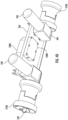
- FIGS. 4E-4F illustrates an enhanced perspective view of an example driven wheel hub 218A
- FIG. 4F illustrates an enhanced perspective view of an example motor 240 and gear box 442.
- the driven wheel hub 218A may be attached to the rear axle 222 so that the rear axle 222 and the driven wheel hub 218A rotate together.
- two separate rear axles 222 are provided, with a rear axle 222 being used with a respective driven wheel hub 218A.
- the driven wheels 218 see FIG. 4B
- the driven wheel hubs 218A may be rotated at different rotational speeds so that the wheelchair assembly may be permitted to rotate.
- any rear manual wheel subassembly 650 (see FIG. 6D ) attached to the seat subassembly 202 may be removed. This may be done by removing any fasteners that are connecting the two subassemblies. With the rear manual wheel subassembly 650 being removed, the motor subassembly 204 may be provided in place of the rear manual wheel subassembly 650.
- a user may position the seat subassembly 202 on the motor subassembly 204, with the seat subassembly 202 resting on the connection bar 221 as illustrated in FIG. 2C .
- the protrusions 421B ( see FIG. 4B ) on the connection bar 221 may assist the user in positioning the seat subassembly 202 to expedite the assembly.
- Fasteners such as toggle pins may be used to secure the seat subassembly 202 to the connection bar 221 and/or other components of the motor subassembly 204.
- the arms 232 see FIG. 4A
- a motor controller 738 see FIG.
- the motor controller 738 may be attached to the motor subassembly 204. Furthermore, wiring may be extended from the motor controller 738 to other components on the seat subassembly 202 such as the battery box 230 ( see FIG. 3A ) and the input device 126 ( see FIG. 1 ). Wiring may also be extended from the motor controller 738 to the motors 240 ( see FIG. 4A ).
- FIG. 5A illustrates a perspective view of an example battery box 230 disposed on the seat subassembly 202.
- FIG. 5B illustrates a perspective view of an example bottom portion 230A of the battery box 230 of FIG. 5A .
- FIG. 5C illustrates a perspective view of an example top portion 230B of the battery box 230 of FIG. 5A .
- the battery box 230 may be disposed on the seat frame 206 ( see FIG. 2A ) of the seat subassembly 202.
- the battery box 230 may be disposed directly underneath the seat 502A where an occupant will be positioned.
- the battery box 230 may be provided in front of the center of gravity for the wheelchair assembly 200 (see FIG.
- the bottom portion 230A of the battery box 230 may define an internal cavity.
- the top portion 230B of the battery box 230 may also define an internal cavity.
- the two internal cavities of the two portions may define an internal volume where a battery 730' ( see FIG. 7 ) may be stored.
- the bottom portion 230A and the top portion 230B may be attached together and sealed so that water, moisture, dust, and other contaminants are prevented from affecting the internal contents of the battery box 230 (e.g., the battery).
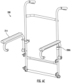
- the seat subassembly 202 may include several different frames, and FIGS. 6A-6C illustrate various perspective view of these frames in isolation.
- FIG. 6A illustrates a perspective view of an example footrest frame 210
- FIG. 6B illustrates a perspective view of an example seat frame 206
- FIG. 6C illustrates a perspective view of an example backrest frame 208.
- the occupant armrest 214 may be pivotably attached to the remainder of the backrest frame 208.
- Stops 208A may be provided on the backrest frame 208 to prevent rotation of an occupant armrest 214 past a deployed position.
- Frames may comprise lightweight material such as stainless steel or another lightweight metal. However, other materials may also be used in the frames.
- FIG. 6D illustrates a perspective view of an example rear manual wheel subassembly 650.
- the rear manual wheel subassembly 650 may include a rear axle 621A, and rear wheels 618' may be attached at each end of the rear axle 621A.
- the rear axle 621A may be installed at the same position as the connection arm 221 relative to the seat subassembly 202.
- the rear manual wheel subassembly 650 may be disassembled by removing fasteners in the form of toggle pins so that the rear wheels 618' can be removed from the rear axle 621A.
- FIG. 7 illustrates a rear view of an example control system 700 with a controller 738 and other electrical components that may be connected to the controller 738 to form an electrical control assembly.
- the controller 738 may be deployed in a motor controller box having a top portion 238A ( see FIG. 4C ) and a bottom portion 438B ( see FIG. 4C ).
- the controller 738 may include a first bus 746A and a second bus 746B.
- a first input device 726A may be connected to the first bus 746A, and a second input device 726B may be connected to the second bus 746B.
- a first motor 740A and a second motor 740B may also be connected to the controller 738, and a first park brake 744A and a second park brake 744B may also be connected to the controller 738.
- One or more batteries 730' and an on-board charger 748 may also be provided that are connected to the controller 738.
- the park brakes 740A, 740B may be automatically activated. This may be beneficial to prevent accidents if power is lost while the wheelchair assembly 100 ( see FIG. 1 ) is operating on an incline.
- one or more levers (such as on the motor directly) may be manipulated to cause the motors to disengage and enable manual operation of the wheelchair.
- commands may be received from a user at the first input device 726A or the second input device 726B to operate in electrical mode or a manual mode.
- Operating in an electrical mode may result in the park brakes 740A, 740B being active to prevent movement of the wheelchair assembly 100 when no movement commands are received from the input devices 726A, 726B, and this may be beneficial for safety reasons.
- a user may switch to a manual mode to prevent the park brakes 740A, 740B from being applied, and a user may then move the wheelchair assembly 100 manually.
Landscapes
- Health & Medical Sciences (AREA)
- Life Sciences & Earth Sciences (AREA)
- Animal Behavior & Ethology (AREA)
- General Health & Medical Sciences (AREA)
- Public Health (AREA)
- Veterinary Medicine (AREA)
- Handcart (AREA)
- Electric Propulsion And Braking For Vehicles (AREA)
- Motorcycle And Bicycle Frame (AREA)
Claims (11)
- Ensemble fauteuil roulant (100, 200) pour un montage et un démontage aisés, l'ensemble fauteuil roulant comprenant :une pluralité de châssis (106, 108, 110, 206, 208, 210) ;au moins un moteur (240) ;une batterie (730') ; etune pluralité de roues (116, 118, 120, 216, 218, 220A),dans lequel l'ensemble fauteuil roulant comprend une pluralité de sous-ensembles (202, 204), dans lequel chacun de la pluralité de sous-ensembles pèse moins de trente-cinq, 35, kilogrammes, et dans lequel chacun de la pluralité de sous-ensembles est configuré pour être sélectivement fixé ou démonté les uns avec les autres pour former l'ensemble fauteuil roulant.
- Ensemble fauteuil roulant de la revendication 1, dans lequel la pluralité de sous-ensembles comprend un premier sous-ensemble (202) et un deuxième sous-ensemble (204), dans lequel le premier sous-ensemble comprend la batterie (730'), dans lequel le deuxième sous-ensemble comprend l'au moins un moteur (240), dans lequel le premier sous-ensemble est configuré pour être sélectivement fixé au deuxième sous-ensemble.
- Ensemble fauteuil roulant selon la revendication 2, dans lequel la batterie (730') est prévue dans un sous-ensemble différent de l'au moins un moteur (240) pour répartir plus uniformément le poids de l'ensemble fauteuil roulant (100, 200) et de sorte que le poids du premier sous-ensemble et du deuxième sous-ensemble soient tous deux inférieurs à trente-cinq, 35, kilogrammes.
- Ensemble fauteuil roulant de la revendication 1, dans lequel la batterie (730') et l'au moins un moteur (240) sont séparés par une distance horizontale d'au moins deux cent cinq, 205, millimètres lorsque l'ensemble fauteuil roulant est entièrement monté et orienté dans une position verticale de manière à former un centre de gravité entre eux.
- Ensemble fauteuil roulant selon la revendication 1, comprenant en outre :
un jeu supplémentaire d'une ou plusieurs roues (618') qui sont prévues à l'arrière de l'ensemble fauteuil roulant, dans lequel le jeu supplémentaire d'une ou plusieurs roues est configuré pour empêcher l'ensemble fauteuil roulant de basculer vers l'arrière. - Ensemble fauteuil roulant selon la revendication 5, dans lequel le jeu supplémentaire d'une ou plusieurs roues (618') est configuré pour empêcher l'au moins un moteur (240) d'entrer en contact avec le sol lorsque l'au moins un moteur est assemblé.
- Ensemble fauteuil roulant selon la revendication 1, comprenant en outre un ensemble de commande électronique qui est configuré pour commander le mouvement de l'ensemble fauteuil roulant.
- Ensemble fauteuil roulant selon la revendication 7, dans lequel l'ensemble de commande électronique est configuré pour recevoir des commandes de l'utilisateur, dans lequel l'ensemble de commande électronique est configuré pour régler la direction ou la vitesse de l'ensemble fauteuil roulant.
- Ensemble fauteuil roulant selon la revendication 8, comprenant en outre un accoudoir d'occupant (114), dans lequel l'ensemble de commande électronique comprend un joystick (128) configuré pour recevoir des commandes de l'utilisateur, dans lequel le joystick est positionné à proximité de l'accoudoir d'occupant de sorte que le joystick soit configuré pour être actionné par un occupant.
- Ensemble fauteuil roulant de la revendication 1, dans lequel l'ensemble fauteuil roulant définit une direction avant-arrière, dans lequel l'ensemble fauteuil roulant (100, 200) définit un centre de gravité, dans lequel un sous-ensemble moteur (204) définit un centre de gravité, dans lequel le centre de gravité pour le sous-ensemble moteur est prévu à l'arrière du centre de gravité pour l'ensemble fauteuil roulant le long de la direction avant-arrière, dans lequel la batterie (730') définit un centre de gravité, dans lequel le centre de gravité pour la batterie est prévu à l'avant du centre de gravité pour l'ensemble fauteuil roulant le long de la direction avant-arrière.
- Ensemble fauteuil roulant selon la revendication 1, dans lequel les roues (116, 118, 120, 216, 218, 220A) sont des pneus ballon basse pression.
Applications Claiming Priority (1)
| Application Number | Priority Date | Filing Date | Title |
|---|---|---|---|
| US202263404558P | 2022-09-08 | 2022-09-08 |
Publications (3)
| Publication Number | Publication Date |
|---|---|
| EP4335423A1 EP4335423A1 (fr) | 2024-03-13 |
| EP4335423B1 true EP4335423B1 (fr) | 2025-06-04 |
| EP4335423C0 EP4335423C0 (fr) | 2025-06-04 |
Family
ID=88016448
Family Applications (1)
| Application Number | Title | Priority Date | Filing Date |
|---|---|---|---|
| EP23195758.0A Active EP4335423B1 (fr) | 2022-09-08 | 2023-09-06 | Fauteuil roulant électrique tout terrain et ensemble correspondant |
Country Status (5)
| Country | Link |
|---|---|
| US (1) | US20240082082A1 (fr) |
| EP (1) | EP4335423B1 (fr) |
| CN (1) | CN117653470A (fr) |
| AU (1) | AU2023226674B2 (fr) |
| PL (1) | PL4335423T3 (fr) |
Family Cites Families (23)
| Publication number | Priority date | Publication date | Assignee | Title |
|---|---|---|---|---|
| US3749192A (en) * | 1971-07-16 | 1973-07-31 | A Karchak | Collapsible wheel chair |
| US5156226A (en) * | 1988-10-05 | 1992-10-20 | Everest & Jennings, Inc. | Modular power drive wheelchair |
| EP0740542B1 (fr) * | 1994-11-18 | 2005-02-02 | Degonda-Rehab S.A. | Siege roulant pour le transport ou l'assistance au deplacement d'au moins un utilisateur, notamment d'une personne handicapee |
| EP1417948A1 (fr) * | 2002-10-28 | 2004-05-12 | Pride Mobility Products, Corporation | Fauteuil roulant motorisé transportable |
| GB2407075B (en) * | 2003-10-13 | 2007-06-06 | Sunrise Medical Ltd | Personal mobility vehicle having releasably connected frame parts |
| TW200810738A (en) * | 2006-08-31 | 2008-03-01 | Kwang Yang Motor Co | Chassis device of electric wheelchair |
| US8727048B2 (en) * | 2009-11-15 | 2014-05-20 | Invacare Corp. | Wheelchair |
| US20120279789A1 (en) * | 2011-05-02 | 2012-11-08 | Bradley Brill | Detachable power drive unit for propelling and steering manual wheelchairs |
| US8678402B2 (en) * | 2012-08-06 | 2014-03-25 | Arlen Helterbrand | Portable convertible wheelchair |
| US20150053490A1 (en) * | 2013-08-25 | 2015-02-26 | Amy Green Santagata | Battery powered all terrain wheelchair |
| US9554954B2 (en) * | 2014-02-07 | 2017-01-31 | Theresa L. Hutchins | Convertible wheelchair |
| CN204072536U (zh) * | 2014-09-26 | 2015-01-07 | 昆山奥仕达电动科技有限公司 | 电动轮椅 |
| CN205083841U (zh) * | 2015-09-29 | 2016-03-16 | 詹淑真 | 可拆卸的电动轮椅 |
| CN206355249U (zh) * | 2016-10-21 | 2017-07-28 | 金华市伊凯动力科技有限公司 | 一种可折叠防倾轮以及包含该防倾轮的电动轮椅车 |
| AR110092A1 (es) * | 2016-11-22 | 2019-02-20 | Ig Cardboard Technologies Ltd | Silla de ruedas |
| DE102016124424A1 (de) * | 2016-12-14 | 2018-06-14 | Sunrise Medical Gmbh | Modulare Radanordnung für einen Rollstuhl |
| US10335331B2 (en) * | 2017-03-31 | 2019-07-02 | Inventit Products, Inc. | Powered wheelchair, wheelchair powering device and method |
| US10945900B1 (en) * | 2017-11-08 | 2021-03-16 | Jeffrey J. Ousborne | Powered wheelchair for beach terrain |
| CN209695597U (zh) * | 2018-11-10 | 2019-11-29 | 格罗贝尔机电(上海)有限公司 | 一种四轮驱动电动轮椅 |
| KR102275618B1 (ko) * | 2019-01-29 | 2021-07-13 | 엘지전자 주식회사 | 전동 휠체어 및 그 제어방법 |
| US20220000688A1 (en) * | 2020-01-15 | 2022-01-06 | Michele Marie Klein | FOLDING ELECTRIC WHEELCHAIR with ELEVATING SEAT |
| CN111407541A (zh) * | 2020-03-23 | 2020-07-14 | 西安星球通智能装备技术有限公司 | 一种具有防倾倒功能的轮椅 |
| CN216394500U (zh) * | 2021-11-08 | 2022-04-29 | 广州视源电子科技股份有限公司 | 防倾支架、动力总成及轮椅 |
-
2023
- 2023-09-06 PL PL23195758.0T patent/PL4335423T3/pl unknown
- 2023-09-06 US US18/461,783 patent/US20240082082A1/en active Pending
- 2023-09-06 EP EP23195758.0A patent/EP4335423B1/fr active Active
- 2023-09-06 AU AU2023226674A patent/AU2023226674B2/en active Active
- 2023-09-08 CN CN202311156663.8A patent/CN117653470A/zh active Pending
Also Published As
| Publication number | Publication date |
|---|---|
| AU2023226674A1 (en) | 2024-03-28 |
| CN117653470A (zh) | 2024-03-08 |
| AU2023226674B2 (en) | 2025-02-27 |
| PL4335423T3 (pl) | 2025-08-18 |
| US20240082082A1 (en) | 2024-03-14 |
| EP4335423A1 (fr) | 2024-03-13 |
| EP4335423C0 (fr) | 2025-06-04 |
Similar Documents
| Publication | Publication Date | Title |
|---|---|---|
| US6341657B1 (en) | Suspension for central drive vehicle | |
| US5351774A (en) | Powered wheelchair with a detachable power drive assembly | |
| US6684969B1 (en) | Changeable personal mobility vehicle | |
| US4570739A (en) | Personal mobility vehicle | |
| EP1562818B1 (fr) | Vehicule modulaire de deplacement | |
| US5697465A (en) | Personal mobility vehicle | |
| US20100126789A1 (en) | Personal Vehicles | |
| US8186463B2 (en) | Wheelchair with middle wheel drive | |
| US7866422B2 (en) | Electric golf cart and utility cart | |
| EP0973475B1 (fr) | Fauteuil roulant motorise capable de monter sur des bordures de trottoir | |
| US8118120B2 (en) | Power wheel chair | |
| US7971893B1 (en) | Wheelchair | |
| US12186246B2 (en) | Indoor and outdoor mobility device system | |
| US20220000688A1 (en) | FOLDING ELECTRIC WHEELCHAIR with ELEVATING SEAT | |
| US20210212871A1 (en) | Folding electric wheelchair | |
| US8113305B1 (en) | Powered patient transport vehicle | |
| US9289339B2 (en) | Personal mobility vehicle | |
| EP4335423B1 (fr) | Fauteuil roulant électrique tout terrain et ensemble correspondant | |
| HK40102384A (zh) | 全地形电动轮椅及相应组件 | |
| JPH08112316A (ja) | 電動介護用車椅子 | |
| Stacey | Wheelchairs: user requirements and different features | |
| GB2484206A (en) | A stand-up personal mobility vehicle with thigh supports mounted on folding column |
Legal Events
| Date | Code | Title | Description |
|---|---|---|---|
| PUAI | Public reference made under article 153(3) epc to a published international application that has entered the european phase |
Free format text: ORIGINAL CODE: 0009012 |
|
| STAA | Information on the status of an ep patent application or granted ep patent |
Free format text: STATUS: THE APPLICATION HAS BEEN PUBLISHED |
|
| AK | Designated contracting states |
Kind code of ref document: A1 Designated state(s): AL AT BE BG CH CY CZ DE DK EE ES FI FR GB GR HR HU IE IS IT LI LT LU LV MC ME MK MT NL NO PL PT RO RS SE SI SK SM TR |
|
| STAA | Information on the status of an ep patent application or granted ep patent |
Free format text: STATUS: REQUEST FOR EXAMINATION WAS MADE |
|
| 17P | Request for examination filed |
Effective date: 20240913 |
|
| RBV | Designated contracting states (corrected) |
Designated state(s): AL AT BE BG CH CY CZ DE DK EE ES FI FR GB GR HR HU IE IS IT LI LT LU LV MC ME MK MT NL NO PL PT RO RS SE SI SK SM TR |
|
| RAP3 | Party data changed (applicant data changed or rights of an application transferred) |
Owner name: ASIAN PRIME SOURCES LIMITED |
|
| GRAP | Despatch of communication of intention to grant a patent |
Free format text: ORIGINAL CODE: EPIDOSNIGR1 |
|
| STAA | Information on the status of an ep patent application or granted ep patent |
Free format text: STATUS: GRANT OF PATENT IS INTENDED |
|
| INTG | Intention to grant announced |
Effective date: 20250221 |
|
| GRAS | Grant fee paid |
Free format text: ORIGINAL CODE: EPIDOSNIGR3 |
|
| GRAA | (expected) grant |
Free format text: ORIGINAL CODE: 0009210 |
|
| STAA | Information on the status of an ep patent application or granted ep patent |
Free format text: STATUS: THE PATENT HAS BEEN GRANTED |
|
| AK | Designated contracting states |
Kind code of ref document: B1 Designated state(s): AL AT BE BG CH CY CZ DE DK EE ES FI FR GB GR HR HU IE IS IT LI LT LU LV MC ME MK MT NL NO PL PT RO RS SE SI SK SM TR |
|
| REG | Reference to a national code |
Ref country code: GB Ref legal event code: FG4D |
|
| REG | Reference to a national code |
Ref country code: CH Ref legal event code: EP |
|
| REG | Reference to a national code |
Ref country code: DE Ref legal event code: R096 Ref document number: 602023003815 Country of ref document: DE |
|
| REG | Reference to a national code |
Ref country code: IE Ref legal event code: FG4D |
|
| U01 | Request for unitary effect filed |
Effective date: 20250620 |
|
| U07 | Unitary effect registered |
Designated state(s): AT BE BG DE DK EE FI FR IT LT LU LV MT NL PT RO SE SI Effective date: 20250701 |
|
| PG25 | Lapsed in a contracting state [announced via postgrant information from national office to epo] |
Ref country code: ES Free format text: LAPSE BECAUSE OF FAILURE TO SUBMIT A TRANSLATION OF THE DESCRIPTION OR TO PAY THE FEE WITHIN THE PRESCRIBED TIME-LIMIT Effective date: 20250604 |
|
| PG25 | Lapsed in a contracting state [announced via postgrant information from national office to epo] |
Ref country code: GR Free format text: LAPSE BECAUSE OF FAILURE TO SUBMIT A TRANSLATION OF THE DESCRIPTION OR TO PAY THE FEE WITHIN THE PRESCRIBED TIME-LIMIT Effective date: 20250905 Ref country code: NO Free format text: LAPSE BECAUSE OF FAILURE TO SUBMIT A TRANSLATION OF THE DESCRIPTION OR TO PAY THE FEE WITHIN THE PRESCRIBED TIME-LIMIT Effective date: 20250904 |
|
| PGFP | Annual fee paid to national office [announced via postgrant information from national office to epo] |
Ref country code: PL Payment date: 20250821 Year of fee payment: 3 |
|
| PG25 | Lapsed in a contracting state [announced via postgrant information from national office to epo] |
Ref country code: HR Free format text: LAPSE BECAUSE OF FAILURE TO SUBMIT A TRANSLATION OF THE DESCRIPTION OR TO PAY THE FEE WITHIN THE PRESCRIBED TIME-LIMIT Effective date: 20250604 |
|
| PG25 | Lapsed in a contracting state [announced via postgrant information from national office to epo] |
Ref country code: RS Free format text: LAPSE BECAUSE OF FAILURE TO SUBMIT A TRANSLATION OF THE DESCRIPTION OR TO PAY THE FEE WITHIN THE PRESCRIBED TIME-LIMIT Effective date: 20250904 |
|
| U20 | Renewal fee for the european patent with unitary effect paid |
Year of fee payment: 3 Effective date: 20250929 |
|
| PG25 | Lapsed in a contracting state [announced via postgrant information from national office to epo] |
Ref country code: IS Free format text: LAPSE BECAUSE OF FAILURE TO SUBMIT A TRANSLATION OF THE DESCRIPTION OR TO PAY THE FEE WITHIN THE PRESCRIBED TIME-LIMIT Effective date: 20251004 |
|
| PG25 | Lapsed in a contracting state [announced via postgrant information from national office to epo] |
Ref country code: SM Free format text: LAPSE BECAUSE OF FAILURE TO SUBMIT A TRANSLATION OF THE DESCRIPTION OR TO PAY THE FEE WITHIN THE PRESCRIBED TIME-LIMIT Effective date: 20250604 |
|
| PG25 | Lapsed in a contracting state [announced via postgrant information from national office to epo] |
Ref country code: CZ Free format text: LAPSE BECAUSE OF FAILURE TO SUBMIT A TRANSLATION OF THE DESCRIPTION OR TO PAY THE FEE WITHIN THE PRESCRIBED TIME-LIMIT Effective date: 20250604 |
|
| PG25 | Lapsed in a contracting state [announced via postgrant information from national office to epo] |
Ref country code: SK Free format text: LAPSE BECAUSE OF FAILURE TO SUBMIT A TRANSLATION OF THE DESCRIPTION OR TO PAY THE FEE WITHIN THE PRESCRIBED TIME-LIMIT Effective date: 20250604 |
|
| PLBE | No opposition filed within time limit |
Free format text: ORIGINAL CODE: 0009261 |
|
| STAA | Information on the status of an ep patent application or granted ep patent |
Free format text: STATUS: NO OPPOSITION FILED WITHIN TIME LIMIT |
|
| REG | Reference to a national code |
Ref country code: CH Ref legal event code: L10 Free format text: ST27 STATUS EVENT CODE: U-0-0-L10-L00 (AS PROVIDED BY THE NATIONAL OFFICE) Effective date: 20260416 |