EP4335424A1 - Dispositif de réglage pour l'accouplement amovible d'un dossier à un siège - Google Patents
Dispositif de réglage pour l'accouplement amovible d'un dossier à un siège Download PDFInfo
- Publication number
- EP4335424A1 EP4335424A1 EP23196765.4A EP23196765A EP4335424A1 EP 4335424 A1 EP4335424 A1 EP 4335424A1 EP 23196765 A EP23196765 A EP 23196765A EP 4335424 A1 EP4335424 A1 EP 4335424A1
- Authority
- EP
- European Patent Office
- Prior art keywords
- adjustment device
- linear actuator
- seatback
- seat
- adjuster
- Prior art date
- Legal status (The legal status is an assumption and is not a legal conclusion. Google has not performed a legal analysis and makes no representation as to the accuracy of the status listed.)
- Granted
Links
Images


Classifications
-
- A—HUMAN NECESSITIES
- A61—MEDICAL OR VETERINARY SCIENCE; HYGIENE
- A61G—TRANSPORT, PERSONAL CONVEYANCES, OR ACCOMMODATION SPECIALLY ADAPTED FOR PATIENTS OR DISABLED PERSONS; OPERATING TABLES OR CHAIRS; CHAIRS FOR DENTISTRY; FUNERAL DEVICES
- A61G5/00—Chairs or personal conveyances specially adapted for patients or disabled persons, e.g. wheelchairs
- A61G5/10—Parts, details or accessories
- A61G5/1056—Arrangements for adjusting the seat
- A61G5/1067—Arrangements for adjusting the seat adjusting the backrest relative to the seat portion
-
- A—HUMAN NECESSITIES
- A61—MEDICAL OR VETERINARY SCIENCE; HYGIENE
- A61G—TRANSPORT, PERSONAL CONVEYANCES, OR ACCOMMODATION SPECIALLY ADAPTED FOR PATIENTS OR DISABLED PERSONS; OPERATING TABLES OR CHAIRS; CHAIRS FOR DENTISTRY; FUNERAL DEVICES
- A61G5/00—Chairs or personal conveyances specially adapted for patients or disabled persons, e.g. wheelchairs
- A61G5/10—Parts, details or accessories
- A61G5/1056—Arrangements for adjusting the seat
- A61G5/1064—Arrangements for adjusting the seat adjusting the depth of the seat
Definitions
- the present disclosure is directed to a device for adjusting the position of a seatback relative to a seat.
- United States Patent No. 6,938,955 discloses a powered lumbar support mechanism including a lumbar plate having a power mechanism having connecting links connected to opposite ends of the plate. One of the connecting links is longitudinally movable to change the convexity of the outer surface of the plate to adjust the lumbar support.
- the power mechanism includes a housing which retains a threaded rod threaded into a worm gear mechanism held within the housing. The housing also retains a motor having a worm which drives the threaded worm gear.
- the housing can also incorporate a second threaded rod, threaded to a second threaded worm gear also fixed within the housing such that the end of the second threaded rod is connected to a seat support so as to allow for the adjustability of the vertical position of the lumbar mechanism.
- United States Patent No. 7,918,506 discloses a padding structure for a chair including a back support, a seat plate, a foam disposed on the back support, two guiding lines mounted on the back support, and two guiding lines mounted on the seat plate.
- Each guiding line of the back support and the seat plate is connected with a resilient member to control flexibility of the resilient member.
- An adjustable member is used to control the expansion and retraction of the guiding lines to drive the resilient members to change their radii of curvature, correcting the user's improper posture.
- United States Patent No. 8,360,523 discloses an adjusting device for a lumbar support having a pair of spaced guide members, an adjusting member coupled to the pair of guide members, and a drive mechanism for effecting an adjustment of the lumbar support.
- the adjusting member is displaceable along the pair of guide members and configured such that the lumbar support is adjusted when the adjusting member is displaced.
- the drive mechanism comprises a motor, which is provided on the adjusting member so as to be displaceable along the guide members jointly with the adjusting member.
- the motor may be coupled to a shaft having a structured exterior surface, the drive mechanism being configured to effect a relative displacement between the adjusting member and the shaft.
- the present disclosure relates to an adjustment device for removably coupling a seatback to a seat.
- the adjustment device can include: a first adjuster for adjusting a linear position of the seatback relative to the seat; and a second adjuster for adjusting an angular position of the seatback relative to the seat.
- the first adjuster can include a first linear actuator.
- the adjustment device can include a main body and a sliding bed, and the first linear actuator can link the main body and the sliding bed such that actuating the first linear actuator can cause linear displacement of the sliding bed relative to the main body.
- the first linear actuator can include a first cylindrical worm, and threads of the first linear actuator can mesh with a threaded recess of the sliding bed.
- the first linear actuator can be actuated about a first axis, and the sliding bed can translate between first and second linear positions in a direction that is parallel to the first axis.
- the second adjuster can include a second linear actuator.
- the adjustment device can include a sliding bed and an angle plate pivotably coupled to the sliding bed, and the second linear actuator can link the sliding bed and the angle plate such that actuating the second linear actuator can cause angular displacement of the angle plate relative to the sliding bed.
- the second linear actuator can comprise a second cylindrical worm, and worm threads of the second linear actuator can mesh with teeth of the angle plate.
- the second linear actuator can be actuated about a second axis, and the angle plate can rotate between first and second angular positions about an axis that is perpendicular to the second axis.
- the first adjuster and the second adjuster can be independently actuatable to change the position of the seatback relative to the seat.
- Each of the first linear actuator and the second linear actuator can be manually actuatable.
- the first linear actuator and the second linear actuator can be each actuatable from a rear side of the adjustment device.
- the adjustment device can include a seatback coupling mechanism for removably securing the adjustment device to the seatback.
- the seatback coupling mechanism can include: a bracket including a first portion for coupling to the seatback, and a second portion including upper and lower pins; and a latching plate including a notch and a hook for receiving the upper and lower pins, respectively, to connect the adjustment device and the seatback.
- the seatback coupling mechanism can include a latch moveable between an unlocked position in which the latch is clear of the notch, and a locked position in which the latch restricts the upper pin within the notch.
- the adjustment device can include a seat coupling mechanism for removably securing the adjustment device to a frame of the seat.
- the seat coupling mechanism can include a clamp that is configured to be secured to a frame of the seat.
- the seat coupling mechanism can be adjustable to raise and lower the seatback relative to the seat.
- the present disclosure relates to an adjustment device for coupling a seatback to a seat.
- the adjustment device can include: a first worm gear; and a second worm gear.
- the first and second worm gears are each independently and manually actuatable to change a position of the seatback relative to the seat.
- the present disclosure relates to an apparatus for adjusting a position of a first seat component relative to a second seat component.
- the apparatus can include a linear actuator, a main body and a sliding bed.
- the linear actuator can link the main body and the sliding bed such that actuating the linear actuator causes linear displacement of the sliding bed relative to the main body.
- the linear actuator can include a cylindrical worm, and threads of the linear actuator can mesh with a threaded recess of the sliding bed.
- the linear actuator can be manually actuated about an axis, and the sliding bed can translate between first and second linear positions in a direction that is parallel to the axis.
- the present disclosure relates to an apparatus for adjusting a position of a first seat component relative to a second seat component.
- the apparatus can include a linear actuator, a bed and an angle plate pivotably coupled to the bed.
- the linear actuator can link the bed and the angle plate such that actuating the linear actuator causes angular displacement of the angle plate relative to the bed.
- the linear actuator can include a cylindrical worm, and worm threads of the linear actuator mesh with teeth of the angle plate.
- the linear actuator can be manually actuated about a first axis, and the angle plate can rotate between first and second angular positions about a second axis that is perpendicular to the first axis.
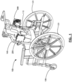
- Figure 1 shows a seat 100, a seatback 110, and two adjustment devices 200 positioned on opposing sides of the seatback 110.
- the adjustment devices 200 support the seatback 110 and are configured to change the position of the seatback 110 relative to the seat 100.
- the seat 100 is in the form of a wheelchair having rear wheels 120, front wheels 130, and a frame 140 (commonly referred to as "canes").
- the adjustment devices 200 are shown coupled both to the frame 140 of the seat 100 and the seatback 110.
- the seat can be a chair without wheels.
- the adjustment devices 200 can change the linear position and/or the angular position of the seatback 110. Changing the position of the seatback 110 relative to the seat 100 can allow different users to use the same seat 100 while adjusting the seatback 110 to their comfort, and/or can allow a user to modify the seat 100 depending on their desired use. Additionally, the seatback 110 can be removably coupled to the seat 100 by the adjustment devices 200, allowing for a change in seatback 110 depending on the desired use of the seat 100.
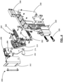
- the adjustment device 200 includes a first adjuster 300 and a second adjuster 320.
- the first adjuster 300 can be used to adjust a linear position of the seatback 110 relative to the seat 100
- the second adjuster 320 can be used to adjust an angular position of the seatback 110 relative to the seat 100.
- the first adjuster 300 includes a first linear actuator 302, and the second adjuster 320 includes a second linear actuator 322.
- each of the actuators 302, 322 takes the form of a cylindrical worm.
- Each of the actuators 302, 322 can be used to actuate their respective adjusters 300, 320 such that the position of the seatback 110 is adjusted relative to the seat 100.
- the adjustment device 200 includes a main body 230 and a sliding bed 240.
- the first linear actuator 302 is received in a threaded recess 242 of the sliding bed 240 and a recess 232 of the main body 230. Threads of the first linear actuator 302 mesh with the threaded recess 242 to form a first worm gear. Accordingly, the first linear actuator 302 mechanically links the main body 230 and the sliding bed 240, and actuating the first linear actuator 302 causes linear displacement of the sliding bed 240 relative to the main body 230.
- the first adjuster 300 is adjustable between a first linear position ( Figure 5 ) and a second linear position ( Figure 6 ). These positions are intended to be exemplary and non-limiting.
- the first linear actuator 302 is actuated about a first axis 304, and the sliding bed 240 translates between the first and second linear positions in a direction that is parallel to the first axis 304.
- the adjustment device 200 includes an angle plate 324.
- the second linear actuator 322 is received in a recess 246 of the sliding bed 240, and the angle plate 324 is pivotably coupled to the sliding bed 240 by a pivot 332. Threads of the second linear actuator 322 mesh with teeth 325 of the angle plate 324 to form a second worm gear. Accordingly, the second linear actuator 322 mechanically links the sliding bed 240 and the angle plate 324, and actuating the second linear actuator 322 causes angular displacement of the angle plate 324 relative to the sliding bed 240.
- the second adjuster 320 is adjustable between a first angular position ( Figure 7 ) and a second angular position ( Figure 8 ). These positions are also intended to be exemplary and non-limiting.
- the second linear actuator 322 is actuated about a second axis 323, which can be parallel to the first axis 304.
- the angle plate 324 rotates between the first and second angular positions about a horizontal axis that is perpendicular to the second axis 323.
- the first adjuster 300 and the second adjuster 320 can each be independently actuatable to change the position of the seatback 110 relative to the seat 100.
- each of the adjusters 300, 320 can be infinitely adjustable between their respective positions, such that any combination of angular and/or linear positional change is possible. Independent actuation of the adjusters 300, 320 can permit modification of the seat 100 and the relative position of the seatback 110 to improve function and/or comfort for a variety of users.
- each of the adjusters 300, 320 can each be manually actuated.
- each of the adjusters 300, 320 includes an engagement member 340.
- the engagement member 340 can be engaged by hand, such as by using fingers to turn them, or by a tool, such as a key that is shaped to mate with the engagement members 340.
- each of the engagement members 340 can be accessible from a rear side of the seatback 110. This can allow for someone to assist a seated user in adjusting the seatback 110.
- the adjustment device 200 includes a seat coupling mechanism 220.
- the seat coupling mechanism 220 includes a clamp 222 coupled to a main body 230.
- One or more fasteners 224 can be used to secure the clamp 222 to the frame 140 of the seat 100 ( Figure 1 ).
- the clamp 222 can be adjustably secured along a height of the frame 140 to raise and lower the seatback 110 relative to the seat 100.
- a plastic spacer sleeve (not shown) can be provided to adapt the clamp 222 for use with canes having a smaller diameter.
- the adjustment device 200 further includes a seatback coupling mechanism 260.
- the seatback coupling mechanism 260 includes a bracket 262, a latching plate 280, and a latch 290.
- the bracket 262 includes a first portion 264 and a second portion 266.
- the first portion 264 of the bracket 262 can be coupled to the seatback 110 by fasteners.
- the second portion 266 of the bracket 262 can include lower and upper pins 274, 276 that are mounted thereon.
- the latching plate 280 is secured to the angle plate 324, and includes a notch 284 and a hook 282 for receiving the pins 274, 276, respectively.
- the lower pin 274 can be retained by the hook 282 to connect the adjustment device 200 and the seatback 110.
- the latch 290 is pivotably mounted to the latching plate 280 and can be moved manually between unlocked and locked positions. Like the engagement members 340, the latch 290 can be accessible from a rear side of the seatback 110 ( Figure 2 ). In the unlocked position, the latch 290 is raised clear of the notch 284 and the upper pin 276 can be received by the notch 284. In the locked position, the latch 290 restricts the upper pin 276 within the notch 284. In this manner, the bracket 262, the latching plate 280, and the latch 290 of the seatback coupling mechanism 260 can operate as a quick release mechanism for connecting and disconnecting the adjustment device 200 and the seatback 110.
- the adjustment device 200 can support the seatback 110, and can be used to adjust the position of the seatback 110 relative to the seat 100.
Landscapes
- Health & Medical Sciences (AREA)
- Life Sciences & Earth Sciences (AREA)
- Animal Behavior & Ethology (AREA)
- General Health & Medical Sciences (AREA)
- Public Health (AREA)
- Veterinary Medicine (AREA)
- Chairs For Special Purposes, Such As Reclining Chairs (AREA)
Applications Claiming Priority (1)
| Application Number | Priority Date | Filing Date | Title |
|---|---|---|---|
| US202263405598P | 2022-09-12 | 2022-09-12 |
Publications (2)
| Publication Number | Publication Date |
|---|---|
| EP4335424A1 true EP4335424A1 (fr) | 2024-03-13 |
| EP4335424B1 EP4335424B1 (fr) | 2026-04-01 |
Family
ID=88017713
Family Applications (1)
| Application Number | Title | Priority Date | Filing Date |
|---|---|---|---|
| EP23196765.4A Active EP4335424B1 (fr) | 2022-09-12 | 2023-09-12 | Dispositif de réglage pour l'accouplement amovible d'un dossier à un siège |
Country Status (3)
| Country | Link |
|---|---|
| US (1) | US12599521B2 (fr) |
| EP (1) | EP4335424B1 (fr) |
| CA (1) | CA3212194A1 (fr) |
Citations (6)
| Publication number | Priority date | Publication date | Assignee | Title |
|---|---|---|---|---|
| US6938955B2 (en) | 2001-10-11 | 2005-09-06 | L&P Property Management Co. | Power lumbar mechanism |
| US20070085300A1 (en) * | 2005-10-14 | 2007-04-19 | Invacare Corporation | Clamping assembly |
| US7918506B2 (en) | 2009-02-06 | 2011-04-05 | Chern Shing Top Co., Ltd. | Padding structure for a chair |
| US8360523B2 (en) | 2009-11-16 | 2013-01-29 | Schukra Geraetebau Gmbh | Adjusting device for a lumbar support and method of adjusting a lumbar support |
| US9943456B2 (en) * | 2013-10-16 | 2018-04-17 | Roho, Inc. | Wheelchair back mounting system |
| US10194745B2 (en) * | 2015-11-06 | 2019-02-05 | The Comfort Companies, Llc | Assembly for mounting and independent multi-direction adjustment of a seat back |
Family Cites Families (21)
| Publication number | Priority date | Publication date | Assignee | Title |
|---|---|---|---|---|
| US4790716A (en) | 1986-06-03 | 1988-12-13 | Mcconnell Sylvia J | Device for handling a wheelchair |
| US5197780A (en) | 1991-02-20 | 1993-03-30 | Fisher Dynamics Corporation | Transmission device for cable control of lumbar support mechanism |
| US5624009A (en) | 1994-06-30 | 1997-04-29 | Benjamin; Kevin S. | Wheelchair lift |
| EP0820749A1 (fr) | 1996-07-22 | 1998-01-28 | Schweizerische Eidgenossenschaft vertreten durch die SM Schweizerische Munitions-unternehmung der Gruppe Rüstung | Fauteuil roulant avec entraínement à moteur |
| DE19728413A1 (de) | 1997-07-03 | 1999-01-07 | Langbein Peter Prof Dr Ing Hab | Geländegängiger und treppensteigender Rollstuhl |
| US6659563B2 (en) * | 2001-10-18 | 2003-12-09 | Invacare Corporation | Adjustable quick release frameless back support for a wheelchair |
| US6983990B2 (en) | 2004-02-03 | 2006-01-10 | L&P Property Management Company | Dual drive power actuator |
| US20060076814A1 (en) * | 2004-10-08 | 2006-04-13 | Ivan Samila | Adjustable backrest on personal mobility aid |
| US20080157581A1 (en) * | 2007-01-03 | 2008-07-03 | Sunrise Medical Hhg Inc. | Wheelchair seat back mount assembly and wheelchair therewith |
| DE202008017896U1 (de) * | 2007-03-08 | 2010-09-23 | Sunrise Medical Hhg Inc., Longmont | Rollstuhlrückenlehne mit Zweipunkt-Montagebeschlagteilen |
| WO2010017183A2 (fr) * | 2008-08-07 | 2010-02-11 | Roho, Inc. | Ensemble de montage pour dossier de fauteuil roulant |
| US8376463B2 (en) * | 2009-04-30 | 2013-02-19 | University of Pittsburgh—of the Commonwealth System of Higher Education | User adjustable wheelchair backrest mounting hardware |
| NZ601865A (en) * | 2010-02-11 | 2014-07-25 | Roho Inc | Wheelchair back mounting assembly |
| CN201888889U (zh) | 2010-11-19 | 2011-07-06 | 上海市西南位育中学 | 舌控轮椅 |
| US8567863B2 (en) * | 2011-03-02 | 2013-10-29 | Aspen Seating, Llc | Back support, orientation mechanism and method |
| CN103826502A (zh) | 2011-10-04 | 2014-05-28 | L&P瑞士持有股份有限公司 | 用于座椅的致动器装置和调节可调节部件的方法 |
| WO2016041087A1 (fr) | 2014-09-18 | 2016-03-24 | Miller Greg Bruce | Chaise réglable |
| US11020297B2 (en) | 2015-12-22 | 2021-06-01 | Stryker Corporation | Powered side rail for a patient support apparatus |
| US11419424B2 (en) * | 2019-06-04 | 2022-08-23 | Anatoli Chernin | Chair backrest adjustment mechanism |
| DE102020114594A1 (de) | 2020-06-02 | 2021-12-02 | Bayerische Motoren Werke Aktiengesellschaft | Verstelleinrichtung zum Verstellen eines Windschilds |
| KR102854851B1 (ko) | 2020-10-08 | 2025-09-04 | 현대자동차 주식회사 | 차량 시트 조절 장치 |
-
2023
- 2023-09-12 EP EP23196765.4A patent/EP4335424B1/fr active Active
- 2023-09-12 US US18/367,035 patent/US12599521B2/en active Active
- 2023-09-12 CA CA3212194A patent/CA3212194A1/fr active Pending
Patent Citations (6)
| Publication number | Priority date | Publication date | Assignee | Title |
|---|---|---|---|---|
| US6938955B2 (en) | 2001-10-11 | 2005-09-06 | L&P Property Management Co. | Power lumbar mechanism |
| US20070085300A1 (en) * | 2005-10-14 | 2007-04-19 | Invacare Corporation | Clamping assembly |
| US7918506B2 (en) | 2009-02-06 | 2011-04-05 | Chern Shing Top Co., Ltd. | Padding structure for a chair |
| US8360523B2 (en) | 2009-11-16 | 2013-01-29 | Schukra Geraetebau Gmbh | Adjusting device for a lumbar support and method of adjusting a lumbar support |
| US9943456B2 (en) * | 2013-10-16 | 2018-04-17 | Roho, Inc. | Wheelchair back mounting system |
| US10194745B2 (en) * | 2015-11-06 | 2019-02-05 | The Comfort Companies, Llc | Assembly for mounting and independent multi-direction adjustment of a seat back |
Also Published As
| Publication number | Publication date |
|---|---|
| EP4335424B1 (fr) | 2026-04-01 |
| US20240082083A1 (en) | 2024-03-14 |
| CA3212194A1 (fr) | 2024-03-12 |
| US12599521B2 (en) | 2026-04-14 |
Similar Documents
| Publication | Publication Date | Title |
|---|---|---|
| US5452868A (en) | Adjustable lumbar support with remote push-button control | |
| CN105026206B (zh) | 用于车辆的座位装置 | |
| CA2521200C (fr) | Siege avec systeme de support reglable | |
| US5195803A (en) | Reclining seat back assembly for a wheelchair | |
| US4647108A (en) | Device for controlling headrest of treatment equipment | |
| AU2013318083B2 (en) | Chair arm assembly | |
| CA2484385A1 (fr) | Siege a dossier inclinable avec appui-dos mobile | |
| CN101795892B (zh) | 车辆头枕 | |
| JPH07248A (ja) | 椅子の調整可能な背もたれ | |
| CN109562709B (zh) | 头枕的无级调节机构 | |
| JP2008511483A (ja) | 調節可能な側部チークを有している自動車用座席 | |
| EP4335424A1 (fr) | Dispositif de réglage pour l'accouplement amovible d'un dossier à un siège | |
| US20220194268A1 (en) | Vehicle seat having a backrest | |
| EP3578151B1 (fr) | Ensemble de dossier et fauteuil roulant correspondant | |
| US5197781A (en) | Reclining apparatus | |
| US7152927B1 (en) | Ratcheted headrest for a recliner chair | |
| EP3982791B1 (fr) | Mécanisme de levage d'appui-tête pour meuble rembourré | |
| JP2023530496A (ja) | 頭部支持組立体及び頭部支持ユニット | |
| JP3012765B2 (ja) | 座席装置 | |
| EP1128793B9 (fr) | Siège basculant à centre de gravité constant pour fauteuil roulant | |
| EP1241047A2 (fr) | Dossiers pour sièges de véhicules | |
| EP0404574A2 (fr) | Chaise roulante | |
| EP3831353B1 (fr) | Ensemble de dossier et fauteuil roulant associé | |
| CN115534774B (zh) | 汽车座椅滑移锁定机构及汽车座椅 | |
| CN220694837U (zh) | 一种腰托调节支架及其座椅 |
Legal Events
| Date | Code | Title | Description |
|---|---|---|---|
| PUAI | Public reference made under article 153(3) epc to a published international application that has entered the european phase |
Free format text: ORIGINAL CODE: 0009012 |
|
| STAA | Information on the status of an ep patent application or granted ep patent |
Free format text: STATUS: THE APPLICATION HAS BEEN PUBLISHED |
|
| AK | Designated contracting states |
Kind code of ref document: A1 Designated state(s): AL AT BE BG CH CY CZ DE DK EE ES FI FR GB GR HR HU IE IS IT LI LT LU LV MC ME MK MT NL NO PL PT RO RS SE SI SK SM TR |
|
| STAA | Information on the status of an ep patent application or granted ep patent |
Free format text: STATUS: REQUEST FOR EXAMINATION WAS MADE |
|
| 17P | Request for examination filed |
Effective date: 20240911 |
|
| RBV | Designated contracting states (corrected) |
Designated state(s): AL AT BE BG CH CY CZ DE DK EE ES FI FR GB GR HR HU IE IS IT LI LT LU LV MC ME MK MT NL NO PL PT RO RS SE SI SK SM TR |
|
| STAA | Information on the status of an ep patent application or granted ep patent |
Free format text: STATUS: EXAMINATION IS IN PROGRESS |
|
| 17Q | First examination report despatched |
Effective date: 20241024 |
|
| GRAP | Despatch of communication of intention to grant a patent |
Free format text: ORIGINAL CODE: EPIDOSNIGR1 |
|
| STAA | Information on the status of an ep patent application or granted ep patent |
Free format text: STATUS: GRANT OF PATENT IS INTENDED |
|
| INTG | Intention to grant announced |
Effective date: 20250407 |
|
| GRAJ | Information related to disapproval of communication of intention to grant by the applicant or resumption of examination proceedings by the epo deleted |
Free format text: ORIGINAL CODE: EPIDOSDIGR1 |
|
| STAA | Information on the status of an ep patent application or granted ep patent |
Free format text: STATUS: EXAMINATION IS IN PROGRESS |
|
| GRAP | Despatch of communication of intention to grant a patent |
Free format text: ORIGINAL CODE: EPIDOSNIGR1 |
|
| STAA | Information on the status of an ep patent application or granted ep patent |
Free format text: STATUS: GRANT OF PATENT IS INTENDED |
|
| INTC | Intention to grant announced (deleted) | ||
| INTG | Intention to grant announced |
Effective date: 20251110 |
|
| GRAS | Grant fee paid |
Free format text: ORIGINAL CODE: EPIDOSNIGR3 |
|
| GRAA | (expected) grant |
Free format text: ORIGINAL CODE: 0009210 |
|
| STAA | Information on the status of an ep patent application or granted ep patent |
Free format text: STATUS: THE PATENT HAS BEEN GRANTED |
|
| AK | Designated contracting states |
Kind code of ref document: B1 Designated state(s): AL AT BE BG CH CY CZ DE DK EE ES FI FR GB GR HR HU IE IS IT LI LT LU LV MC ME MK MT NL NO PL PT RO RS SE SI SK SM TR |
|
| P01 | Opt-out of the competence of the unified patent court (upc) registered |
Free format text: CASE NUMBER: UPC_APP_0006703_4335424/2026 Effective date: 20260225 |
|
| REG | Reference to a national code |
Ref country code: CH Ref legal event code: F10 Free format text: ST27 STATUS EVENT CODE: U-0-0-F10-F00 (AS PROVIDED BY THE NATIONAL OFFICE) Effective date: 20260401 Ref country code: GB Ref legal event code: FG4D |
|
| REG | Reference to a national code |
Ref country code: IE Ref legal event code: FG4D |
|
| REG | Reference to a national code |
Ref country code: DE Ref legal event code: R096 Ref document number: 602023014376 Country of ref document: DE |