EP4335493A1 - Cornée périphérique, iris, lentille périphérique, uvea, sclerose, choroïde - Google Patents
Cornée périphérique, iris, lentille périphérique, uvea, sclerose, choroïde Download PDFInfo
- Publication number
- EP4335493A1 EP4335493A1 EP23195440.5A EP23195440A EP4335493A1 EP 4335493 A1 EP4335493 A1 EP 4335493A1 EP 23195440 A EP23195440 A EP 23195440A EP 4335493 A1 EP4335493 A1 EP 4335493A1
- Authority
- EP
- European Patent Office
- Prior art keywords
- light
- myopia
- light source
- pass
- pupillary
- Prior art date
- Legal status (The legal status is an assumption and is not a legal conclusion. Google has not performed a legal analysis and makes no representation as to the accuracy of the status listed.)
- Pending
Links
Images



Classifications
-
- A—HUMAN NECESSITIES
- A61—MEDICAL OR VETERINARY SCIENCE; HYGIENE
- A61N—ELECTROTHERAPY; MAGNETOTHERAPY; RADIATION THERAPY; ULTRASOUND THERAPY
- A61N5/00—Radiation therapy
- A61N5/06—Radiation therapy using light
- A61N5/0613—Apparatus adapted for a specific treatment
- A61N5/0622—Optical stimulation for exciting neural tissue
-
- A—HUMAN NECESSITIES
- A61—MEDICAL OR VETERINARY SCIENCE; HYGIENE
- A61N—ELECTROTHERAPY; MAGNETOTHERAPY; RADIATION THERAPY; ULTRASOUND THERAPY
- A61N5/00—Radiation therapy
- A61N5/06—Radiation therapy using light
- A61N2005/0635—Radiation therapy using light characterised by the body area to be irradiated
- A61N2005/0643—Applicators, probes irradiating specific body areas in close proximity
- A61N2005/0645—Applicators worn by the patient
- A61N2005/0647—Applicators worn by the patient the applicator adapted to be worn on the head
- A61N2005/0648—Applicators worn by the patient the applicator adapted to be worn on the head the light being directed to the eyes
-
- A—HUMAN NECESSITIES
- A61—MEDICAL OR VETERINARY SCIENCE; HYGIENE
- A61N—ELECTROTHERAPY; MAGNETOTHERAPY; RADIATION THERAPY; ULTRASOUND THERAPY
- A61N5/00—Radiation therapy
- A61N5/06—Radiation therapy using light
- A61N2005/065—Light sources therefor
- A61N2005/0651—Diodes
- A61N2005/0652—Arrays of diodes
Definitions
- the present invention relates to a myopia-preventing high intensity illumination apparatus for illuminating eyeballs and surrounding tissue by extra pupillary pathway via light that penetrating periorbital skin, subcutaneous tissue, pass through peripheral cornea, iris, peripheral lens, uvea, sclera, choroid, retinal piment epithelium, specifically a device and method through extra pupillary pathway to apply high intensity illumination to eyeball and periorbital region.
- mice that reared in a box of limited space
- mouse since mouse is a nocturnal animal, it will avoid high intensity light and turn their head and find an angle to low down the light illuminated into their eyeball, many light will fall on their eyelids, only light that partially blocked by eyelids, the reared mouses can stand the light of intensity of 10000 lux shine on their eye region, this is also true when they studied on light of 10000 lux illuminated on healthy human, they found and admitted that their illumination method and light angle is not standardized, in fact healthy human will turn their head to avoid the high intensity light to directly shine into their pupil otherwise their macula will be damaged.
- the outdoor sunlight can easily reach the intensity of 40000-120000 lux and in excess to 200000 lux, in review of photograph taking from sunny seashore we found most people turn their head away from gazing sun, turn their head to the shadow side, or look downward or sideward , to avoid the sun from direct shine into their pupil, if in need of looking at sunny side, they will partially close the eyelids and turn a little downward to prevent sunlight from directly shine into the pupil. This is also true for animal raised in high ambient light, it will avoid ambient light from directly shine through their pupil, especially for nocturnal animal like mouse. Light of intensity greater than 2000 lux will shine on skin of eyelids and pass-through skin or through extra pupillary pathway to illuminate eyeball.
- the light pass through extra pupillary pathway will penetrate the periorbital skin , subcutaneous tissue, pass through peripheral cornea then pass through iris, peripheral lens, into vitreous , then on peripheral retina, or pass backwardly through conjunctiva then pass through sclera, then pass through ciliary body or uvea tract or choroid or pass through retinal pigment epithelium, then backwardly into peripheral retina, the majority of light not convergent by lens to focus on macula, while it fall mostly on the peripheral retina, which is the main retinal area effective in myopia control found by many studies.
- the high intensity light of more than 2000 lux shine eyeball by extra pupillary pathway, it pass through skin, subcutaneous tissue, peripheral cornea, iris, peripheral lens, ciliary body or sclera, uvea tract, choroid, retinal pigment epithelium, partially backwardly into retina, especially on most retina.
- Heart disease and diabetes mellitus is also increased in recent years. Many studies found that high light outdoor illumination has positive effect on decreasing the rate of those diseases.
- ipRGCs provide excitatory drive to dopaminergic amacrine cells and ipRGCs are coupled to GABAergic amacrine cells via gap junctions.
- ipRGCs are coupled to GABAergic amacrine cells via gap junctions.
- dopamine also was suggested as a factor chemical for myopia control, and since the ipRGC connect with so many cells existing in the human orbital system, so many cells, so many chemicals involved, each factor play a role in the control of myopia and human physiology, some prior art with photo therapy focus only on a few photopigments, may neglect important factor in between, besides, many prior arts with photo therapy of front approach, light will inevitably mostly enter pupil zone and shine on small region of retina and by effect of lens the light intensity will be limited to only 1500-2000 lux, their effect on myopia control will be very limited.
- Myopia is a worldwide problem, especially in Asia. Myopia tends to develop in childhood and progress in severity until adulthood. Myopia associates with many disadvantages such as inconvenient in work, cost for glasses or contact lenses as well as increasing eye diseases relate to myopia. Hence, the prevention of progression of myopia is a great health issue.
- One invention CN101858573A depicts a high illuminance classroom lamp, to apply high illuminance light to the students for preventing myopia.
- Another invention EP3141282A1 depicts a device for treating, preventing, or reducing myopia, or the risk thereof, using a display in front of student to apply various lights (illuminance of 0.6 to 1000 lux) to stimulate eyes.
- Another invention US20170072218A depicts a method and apparatus for reducing or preventing myopia, applying a display for temporal stimulate the viewer to prevent myopia.
- Another invention EP2155041A1 depicts a method for determination of optical adjustments to retard myopia progression, providing an anti-myopia lens to retard myopia progression.
- Another invention US9709826B2 depicts a method of applying ocular lens with filtered bands of wavelength to prevent myopia progression.
- Another invention WO2015152818A1 depicts a device to prevent the condition or disease associated with lack of outdoor time, applying a wearable device to monitor the outdoor time of children to prevent myopia progression.
- Another invention CN107707763A depicts a myopia prevention and control wearable device and myopia prevention and control system and method, applying a wearable device for monitor the reading illuminance and reading distance to prevent the progression of myopia.
- Another invention CN106289395A depicts a student myopia prevention and control wearable device, applying a wearable device with ambient light sensor and temperature sensor and laser distance sensor to monitor the student's reading pattern to prevent the myopia progression.
- JP 2018509983 A Samek et al , one of their embodiments depicts VR or AR with extension light therapy device to apply light in front of eyeball region, their light route will pass through pupil, hence their design cannot apply high intensity light therapy to eyeball.
- the primary object of the present invention is to construct a myopia-preventing high intensity illumination apparatus for illuminating eyeballs and surrounding tissues by extra pupillary pathway via light that penetrating periorbital skin, subcutaneous tissue, pass through peripheral cornea, iris, peripheral lens, uvea, sclera, choroid, retinal pigment epithelium, then into retina and vitreous to induce the subtle biochemical reaction which preventing the progression of myopia.
- the light is directed by well-known pupil detection method by aid of computer and camera to prevent high intensity light pass-through pupil into eyeball to injury retina. In this design the light intensity can be elevated to as high as 10000 lux to 200000 lux and keep eyeball safely unharmed.
- the spectrum of light in our invention is preferred to be full spectrum of day light to mimic outdoor activity but due to many theories about what spectrum is effective in myopia prevention is not well proved, the spectrum used will not be limit in our unique extra pupillary lighting method.
- the present invention comprising multiple light source 10, two units for pupil detector 40 and a CPU controller 20 and a battery 21 pack for system power supply; wherein the light source 10 comprises various spectra, and the spectra and composition thereof can be adjusted according to the requirement; the light source 10 can be one type of light source or a composition made up of various light sources, and the illumination level provided by the light source 10 is adjustable and can be adjusted based on different time periods, and the illumination level is greater than 0.5 LUX or program adjusted; the illumination timing of the light source 10 can be continuous, intermittent, or adjusted as preset program, the illumination period and brightness level can be modified and adjusted on the basis of a clock 30, and the illumination time each day can be adjusted according to a requirement with respect to different myopic person.
- the preferred illumination light intensity is averaged but not limited to 40000 - 120000 lux to mimic sunny daylight.
- the preferred light spectrum is full spectrum of sunny daylight but not limited to it.
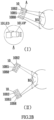
- the light source 10 composed of arrays of customized directed light element ( FIG 2C(I)(II) ) which individually direct light to different eyeball front region to cover the most eyeball front area includes eyelids.
- the light element of light source 10 illuminate the eyeball from an inclined angle compared to visual axis.
- the individual light element can be individually controlled by CPU controller 20 through fine circuit to turn on or off.
- the pupil detection 40 is well-known knowledge, we use it in our invention.
- the pupil detector 40 composed of an infra-red LED light source 40A and a camera 40B, ( FIG. 2C(I)(II) ) the pupil detector 40 will send photo of pupil position to CPU controller 20, the CPU controller 20 will calculate whether the pupil position overlap with the illuminating position of fine individual light element (10B1-10B9) ( FIG. 2A , 2B )of light source 10. In case that any fine individual light element(10B1-10B9) illuminate area overlap with pupil region, ( FIG.
- the CPU controller 20 will calculate it out and shut that fine individual light element off in real time, in order to prevent high intensity light to enter into pupil,
- the light illumination intensity can be as high as 10000 lux to 200000 lux, so keep the light illuminate eyeball only by extra pupillary pathway is necessary for preventing macular and retinal injury.
- the CPU controller 20 is a CPU and is electrically connected to the light source 10 and the clock 30, wherein the controller 20 is electrically connected to a battery 21, and the battery 21 supplies power required for the light source 10, the CPU controller 20 and the clock 30.
- the battery 21 has option of connect to line power supply in case of recharge or high power consumption.
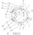
- At least one light source 10 of the present invention is projected to and illuminated on skin surrounding eyes, penetrates subcutaneous tissue A, then pass through peripheral cornea B, iris C, peripheral lens E, ciliary body D, or penetrates peripheral tissue F of eyeball, sclera G, uvea H, choroid I, retinal pigment epithelium J, backwardly enters into vitreous L and retina K, so as to prevent myopia from further progress by inducing microscopic biochemical reactions, which is still not well clarified , despite many theory were proposed, but only high intensive illumination to eyeball succeed in preventing myopia, but every prior art select the front approach without protection of pupil entrance, their practical light intensity will be limited to below 2000 lux, and lost its effect.
- we choose the extra pupillary pathway this is very similar to the outdoor activity of animal and human, that the high intensity outdoor light only passes into eyeball by extra pupillary route.
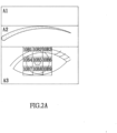
- FIG 2A designate the different illuminated area near eye , light illuminating A1, A2, A3, the intensity can be elevated to 10000 lux to 120000 or in excess to 200000 lux, as real outdoor sunlight, while the fine individual light element(10B1-10B9) of light source 10 illuminate to B1 to B9 area respectively will be controlled by the pupil detector 40, by comparison of overlapping photo calculated by CPU controller 20, any fine individual light element(10B1-10B9) of light source 10 illuminating area within B1 to B9 overlapping with pupil zone, its individual electric power will be shut off by CPU controller 20, its electric power will be on again in time of the overlapping is not continued, the calculating frequency is continuous, in a real time fashion.
- the areas of B1-B9 are 5mm square each, comprises of a total of 15mm square which cover the average human cornea size of 11-12 mm in diameter.
- FIG 2B designates the light pathways of the light source 10, the light source 10 comprises of array of fine individual light element(10B1-10B9) which has customized optic to guide its light direction and were controlled by CPU controller 20, 10LED is the light producing element which produce light, 10LOP is the customized optic for guiding the light direction, the individual light element can stake in horizontal version or vertical version, the light source 10 can be arranged to illuminates from upper position or from upper and lower position.
- the light source 10 illuminate to A1, A2, A3 will not need to be regulated by pupil detector 40, since those area is far away from pupil zone.
- FIG. 2C designates the options of light source arrangement, since the LED technology improved in recent years, we can select LED of high power and small, we can select LED of various spectrum as well as full spectrum preferred in our invention.
- FIG. 2C(I) the LED element with its necessary optic was arranged in a matrix, the 10B1-10B9 fine individual light element was arranged to shine on the corresponding area of B1-B9 respectively above cornea.
- the other light source element 10L need not so delicate was arranged to shine on area of A1, A2, A3 with its necessary customized optic adhere to guide its light direction.
- 40A is a infra-red light source shine on cornea and 40B is a camera for pupil detector.
- the pupil detector is well known technology for decades.
- FIG.2C(II) is an option of 10B1-10B9, be arranged in a horizontal version, pupil detector 40A and 40B be arranged in a more separate version and merged with light source element 10L.
- FIG. 3 is the 1 st embodiment of the present invention
- a light source 10 is provided above an existing pair of glasses 100, and the light source 10 can be clamped and fixed on the pair of glasses 100 by using a clamp, while a CPU controller 20 is clamped and fixed next to the light source 10 and electrically connected to the light source 10.
- Light source 10 comprises fine light elements(10B1-10B9) to shine on peripheral cornea area were merged in frame of light source 10 was regulated by pupil detector to avoid high intensity light shine into pupil.
- FIG. 4 is the 2 nd embodiment of the present invention, at least one light source 10 is clamped and fixed above, below, or laterally to an existing pair of glasses 100, while at least one CPU controller 20 is clamped and fixed next to the light sources 10 and electrically connected to the light sources 10.
- Light source 10 comprises fine light element to shine on cornea area was regulated by pupil detector which merged in frame of light source 10 to avoid high intensity light shine into pupil.
- FIG. 5 is the 3 rd embodiment of the present invention
- a person wears an illumination device frame 200, wherein the illumination device frame 200 is provided thereon with at least one light source 10, while a CPU controller 20 is provided next to the light source 10 and electrically connected to the light source 10; Illumination provided by the light source 10 can be individually controlled, or collectively controlled by a unit related to a main program of the illumination device frame 200.
- Light source 10 comprises fine individual light elements to shine on cornea area was regulated by pupil detector which merged in frame of light source 10 to avoid high intensity light shine into pupil.
- FIG. 6 is the 4 th embodiment of the present invention, A pair of virtual reality (VR) or augmented reality (AR) set 300, wherein the pair of VR or AR set 300 or a frame similar thereto such as other head mount display is provided thereon with at a light source 10, while a CPU controller 20 is provided next to the light source 10 and electrically connected to the light source 10; illumination provided by the light source 10 can be individually controlled, or collectively controlled by a unit related to a main program of the pair of VR or AR set 300 or the frame similar thereto.
- Light source 10 comprises fine individual light elements to shine on peripheral cornea area was regulated by pupil detector which merged in frame of light source to avoid high intensity light shine into pupil.
- FIG. 7 is the 5 th embodiment of the present invention, It comprising a customized glasses frame 400, at least one light source 10 is directly provided on the glasses frame 400 so as to provide illumination, while a CPU controller 20 is provided next to the light source 10 and electrically connected to the light source 10.
- Light source 10 comprises fine individual light elements to shine on peripheral cornea area was regulated by pupil detector which merged in frame of light source 10 to avoid high intensity light shine into pupil.
- FIG. 8 is the 6 th embodiment of the present invention, It comprising a customized headgear 500, and at least one light source 10 is provided on an edge 501 of the headgear 500, while a CPU controller 20 is provided in an adequate position on the headgear 500, and the CPU controller 20 is electrically connected to the light source 10.
- Light source 10 comprises fine individual light elements to shine on peripheral cornea area was regulated by pupil detector which merged in frame of light source 10 to avoid high intensity light shine into pupil.
- the present invention is to construct a device which mimic the outdoor high illumination in real life , the high intensity light of outdoor activity can prevent myopia progression, protect human heart, prevent DM, healthy for human, all have proved by strict study, but the averaged light intensity of sunny daylight is 40000 to 120000 lux and up excess to 200000 , which definitely cannot be allowed to pass directly through pupil into eyeball, the majority of daylight shine mostly on periorbital skin and enter eyeball through an extra pupillary pathway.
- Our invention is to fulfill the high intensity light illumination of outdoor activity and improve the efficiency by wearable, direct extra pupillary illumination, with improved duty time control, intensity control, which will be helpful for people lack outdoor time.
Landscapes
- Health & Medical Sciences (AREA)
- Engineering & Computer Science (AREA)
- Biomedical Technology (AREA)
- Life Sciences & Earth Sciences (AREA)
- Pathology (AREA)
- Neurosurgery (AREA)
- Biophysics (AREA)
- Nuclear Medicine, Radiotherapy & Molecular Imaging (AREA)
- Radiology & Medical Imaging (AREA)
- Animal Behavior & Ethology (AREA)
- General Health & Medical Sciences (AREA)
- Public Health (AREA)
- Veterinary Medicine (AREA)
- Eye Examination Apparatus (AREA)
Applications Claiming Priority (1)
| Application Number | Priority Date | Filing Date | Title |
|---|---|---|---|
| US17/903,046 US20220409924A1 (en) | 2020-09-08 | 2022-09-06 | Myopia-preventing high intensity illumination apparatus for illuminating eyeballs and surrounding tissues via light that penetrating periorbital skin, subcutaneous tissue, then pass through cornea, iris, uvea, sclera and choroid |
Publications (1)
| Publication Number | Publication Date |
|---|---|
| EP4335493A1 true EP4335493A1 (fr) | 2024-03-13 |
Family
ID=87971815
Family Applications (1)
| Application Number | Title | Priority Date | Filing Date |
|---|---|---|---|
| EP23195440.5A Pending EP4335493A1 (fr) | 2022-09-06 | 2023-09-05 | Cornée périphérique, iris, lentille périphérique, uvea, sclerose, choroïde |
Country Status (2)
| Country | Link |
|---|---|
| EP (1) | EP4335493A1 (fr) |
| PH (1) | PH12023050462A1 (fr) |
Citations (18)
| Publication number | Priority date | Publication date | Assignee | Title |
|---|---|---|---|---|
| EP2155041A1 (fr) | 2007-04-27 | 2010-02-24 | The Institute For Eye Research Limited | Détermination d'ajustements optiques pour retarder la progression de la myopie |
| CN101858573A (zh) | 2010-04-15 | 2010-10-13 | 陈宪 | 高照度教室灯 |
| WO2015152818A1 (fr) | 2014-03-31 | 2015-10-08 | National University Of Singapore | Dispositif destiné à empêcher une affection ou une maladie que l'on associe à un manque de temps passé dehors |
| WO2016040534A1 (fr) | 2014-09-09 | 2016-03-17 | LumiThera, Inc. | Dispositifs, systèmes et procédés de photothérapie à plusieurs longueurs d'onde pour le traitement non invasif de tissu endommagé ou malade |
| CN106289395A (zh) | 2016-08-05 | 2017-01-04 | 广州新锐视光学科技有限公司 | 一种学生近视眼防控穿戴式设备 |
| EP3141282A1 (fr) | 2015-09-16 | 2017-03-15 | Frances Joan Rucker | Dispositif pour traiter, prévenir ou réduire la myopie, ou le risque de celle-ci |
| US9709826B2 (en) | 2010-09-28 | 2017-07-18 | Singapore Health Services Pte. Ltd. | Ocular lens |
| CN107707763A (zh) | 2017-10-19 | 2018-02-16 | 杭州镜之镜科技有限公司 | 近视防控可穿戴设备及近视防控系统和方法 |
| JP2018509983A (ja) | 2015-03-16 | 2018-04-12 | マジック リープ,インコーポレイティド | 健康を損う疾病を診断して治療する方法及びシステム |
| US10052497B2 (en) | 2005-07-22 | 2018-08-21 | The Board Of Trustees Of The Leland Stanford Junior University | System for optical stimulation of target cells |
| US20180280718A1 (en) | 2015-12-02 | 2018-10-04 | Tsubota Laboratory, Inc. | Irradiation device |
| US20180345034A1 (en) | 2017-06-06 | 2018-12-06 | Peter Butzloff | Myopia inhibition apparatus and ocular method |
| US20190328577A1 (en) | 2016-03-21 | 2019-10-31 | Ojai Retinal Technology, Llc | System and process for prevention of myopia |
| US20200094015A1 (en) * | 2018-09-25 | 2020-03-26 | Koninklijke Philips N.V. | Controlling light exposure for circadian phase management |
| US20200108272A1 (en) * | 2017-06-08 | 2020-04-09 | Dopavision Gmbh | System and Method to stimulate the optic nerve |
| US20210329764A1 (en) * | 2017-08-02 | 2021-10-21 | Reopia Optics, Inc. | Systems and methods for retarding myopia progression |
| US20210339043A1 (en) * | 2016-11-17 | 2021-11-04 | Cognito Therapeutics, Inc. | Neural stimulation via visual stimulation |
| US20220134047A1 (en) * | 2020-10-29 | 2022-05-05 | Optoceutics ApS | Gamma stimulation pulsing light source system with dosage adjustment for gaze angle |
-
2023
- 2023-08-25 PH PH1/2023/050462A patent/PH12023050462A1/en unknown
- 2023-09-05 EP EP23195440.5A patent/EP4335493A1/fr active Pending
Patent Citations (19)
| Publication number | Priority date | Publication date | Assignee | Title |
|---|---|---|---|---|
| US10052497B2 (en) | 2005-07-22 | 2018-08-21 | The Board Of Trustees Of The Leland Stanford Junior University | System for optical stimulation of target cells |
| EP2155041A1 (fr) | 2007-04-27 | 2010-02-24 | The Institute For Eye Research Limited | Détermination d'ajustements optiques pour retarder la progression de la myopie |
| CN101858573A (zh) | 2010-04-15 | 2010-10-13 | 陈宪 | 高照度教室灯 |
| US9709826B2 (en) | 2010-09-28 | 2017-07-18 | Singapore Health Services Pte. Ltd. | Ocular lens |
| WO2015152818A1 (fr) | 2014-03-31 | 2015-10-08 | National University Of Singapore | Dispositif destiné à empêcher une affection ou une maladie que l'on associe à un manque de temps passé dehors |
| WO2016040534A1 (fr) | 2014-09-09 | 2016-03-17 | LumiThera, Inc. | Dispositifs, systèmes et procédés de photothérapie à plusieurs longueurs d'onde pour le traitement non invasif de tissu endommagé ou malade |
| JP2018509983A (ja) | 2015-03-16 | 2018-04-12 | マジック リープ,インコーポレイティド | 健康を損う疾病を診断して治療する方法及びシステム |
| US20170072218A1 (en) | 2015-09-16 | 2017-03-16 | New England College Of Optometry | Method and Apparatus for Reducing or Preventing Myopia |
| EP3141282A1 (fr) | 2015-09-16 | 2017-03-15 | Frances Joan Rucker | Dispositif pour traiter, prévenir ou réduire la myopie, ou le risque de celle-ci |
| US20180280718A1 (en) | 2015-12-02 | 2018-10-04 | Tsubota Laboratory, Inc. | Irradiation device |
| US20190328577A1 (en) | 2016-03-21 | 2019-10-31 | Ojai Retinal Technology, Llc | System and process for prevention of myopia |
| CN106289395A (zh) | 2016-08-05 | 2017-01-04 | 广州新锐视光学科技有限公司 | 一种学生近视眼防控穿戴式设备 |
| US20210339043A1 (en) * | 2016-11-17 | 2021-11-04 | Cognito Therapeutics, Inc. | Neural stimulation via visual stimulation |
| US20180345034A1 (en) | 2017-06-06 | 2018-12-06 | Peter Butzloff | Myopia inhibition apparatus and ocular method |
| US20200108272A1 (en) * | 2017-06-08 | 2020-04-09 | Dopavision Gmbh | System and Method to stimulate the optic nerve |
| US20210329764A1 (en) * | 2017-08-02 | 2021-10-21 | Reopia Optics, Inc. | Systems and methods for retarding myopia progression |
| CN107707763A (zh) | 2017-10-19 | 2018-02-16 | 杭州镜之镜科技有限公司 | 近视防控可穿戴设备及近视防控系统和方法 |
| US20200094015A1 (en) * | 2018-09-25 | 2020-03-26 | Koninklijke Philips N.V. | Controlling light exposure for circadian phase management |
| US20220134047A1 (en) * | 2020-10-29 | 2022-05-05 | Optoceutics ApS | Gamma stimulation pulsing light source system with dosage adjustment for gaze angle |
Non-Patent Citations (11)
| Title |
|---|
| ASHBY R: "Animal Studies and the Mechanism of Myopia-Protection by Light?", OPTOM VIS SCI, vol. 93, no. 9, September 2016 (2016-09-01), pages 1052 - 4 |
| ASHBY ROHLENDORF ASCHAEFFEL F: "The effect of ambient illuminance on the development of deprivation myopia in chicks", INVEST OPHTHALMOL VIS SCI, vol. 50, no. 11, 10 June 2009 (2009-06-10), pages 5348 - 54, XP055085152, DOI: 10.1167/iovs.09-3419 |
| ASHBY RSSCHAEFFEL F: "The effect of bright light on lens compensation in chicks", INVEST OPHTHALMOL VIS SCI, vol. 51, no. 10, 5 May 2010 (2010-05-05), pages 5247 - 53, XP055068051, DOI: 10.1167/iovs.09-4689 |
| BACKHOUSE SCOLLINS AVPHILLIPS JR: "Influence of periodic vs continuous daily bright light exposure on development of experimental myopia in the chick", OPHTHALMIC PHYSIOL OPT, vol. 33, no. 5, 13 May 2013 (2013-05-13), pages 563 - 72 |
| CHEN SZHI ZRUAN QLIU QLI FWAN FREINACH PSCHEN JQU JZHOU X: "Bright Light Suppresses Form-Deprivation Myopia Development With Activation of Dopamine D1 Receptor Signaling in the ON Pathway in Retina", INVEST OPHTHALMOL VIS SCI, vol. 58, no. 4, 1 April 2017 (2017-04-01), pages 2306 - 2316 |
| GARY E PICKARDPATRICIA J SOLLARS: "Intrinsically photosensitive retinal ganglion cells", REV PHYSIOL BIOCHEM PHARMACOL, vol. 162, 2012, pages 59 - 90 |
| KAROUTA CASHBY RS: "Correlation between light levels and the development of deprivation myopia", INVEST OPHTHALMOL VIS SCI, vol. 56, no. 1, 9 December 2014 (2014-12-09), pages 299 - 309, XP055432455, DOI: 10.1167/iovs.14-15499 |
| NORTON TT: "What Do Animal Studies Tell Us about the Mechanism of Myopia-Protection by Light?", OPTOM VIS SCI, vol. 93, no. 9, September 2016 (2016-09-01), pages 1049 - 51 |
| NORTON TTSIEGWART JT JR: "Light levels, refractive development, and myopia--a speculative review", EXP EYE RES, vol. 114, September 2013 (2013-09-01), pages 48 - 57 |
| OYAMA ET AL.: "Intense Light-Mediated Circadian Cardioprotection via Transcriptional Reprogramming of the Endothelium", CELL REPORTS, vol. 28, 2019, pages 1471 - 1484 |
| SMITH EL 3RDHUNG LFHUANG J: "Protective effects of high ambient lighting on the development of form-deprivation myopia in rhesus monkeys", INVEST OPHTHALMOL VIS SCI, vol. 53, no. 1, 25 January 2012 (2012-01-25), pages 421 - 8, XP007921099, DOI: 10.1167/iovs.11-8652 |
Also Published As
| Publication number | Publication date |
|---|---|
| PH12023050462A1 (en) | 2024-04-22 |
Similar Documents
| Publication | Publication Date | Title |
|---|---|---|
| KR102617590B1 (ko) | 시신경 자극 시스템 및 방법 | |
| JP4630864B2 (ja) | 光刺激を与えるための装置 | |
| RU2580983C2 (ru) | Система для фототерапии, включающая оправы очков и контактные линзы | |
| JP5992449B2 (ja) | 光線療法用の眼鏡 | |
| Wright et al. | Light emitting diodes can be used to phase delay the melatonin rhythm | |
| US12616849B2 (en) | Sunglass lens and sunglass optics for ocular photo-bio-stimulation | |
| Rosenfield | Living with blue light exposure | |
| US20220409924A1 (en) | Myopia-preventing high intensity illumination apparatus for illuminating eyeballs and surrounding tissues via light that penetrating periorbital skin, subcutaneous tissue, then pass through cornea, iris, uvea, sclera and choroid | |
| US20250121206A1 (en) | Wearable Light Therapy Device | |
| Good | Light and eye damage | |
| US20220072333A1 (en) | Myopia-preventing illumination apparatus for illuminating eyeballs and surrounding tissues via light that penetrating periorbital skin, subcutaneous tissue,then pass through cornea, iris, uvea, sclera and choroid | |
| KR102674740B1 (ko) | 눈 주위 피부와 피하조직을 투과한 후 각막, 홍채, 포도막, 공막 및 맥락막을 통과하는 빛을 통해 안구와 주변 조직을 조명하는 근시-방지 조명 장치 | |
| TWI727420B (zh) | 經皮膚、角膜、虹膜、葡萄膜、鞏膜、脈絡膜對眼球及其週邊組織照明之防近視照明器具 | |
| JP7194945B2 (ja) | 近視予防照明器具 | |
| CN112657063B (zh) | 对眼球及其外围组织照明的防近视照明器具 | |
| US12582837B2 (en) | Color balanced sunglass lens for ocular photo-bio-stimulation | |
| RU128494U1 (ru) | Устройство для воздействия на биоритмы человека | |
| RU199083U1 (ru) | Солнцезащитные очки для управления биоритмами | |
| GB2600713A (en) | Myopia-preventing illumination apparatus for illuminating eyeballs and surrounding tissues via light that penetrates periorbital skin and subcutaneous tissue, | |
| FR3114495A1 (fr) | Appareil d’éclairage pour réduire la myopie | |
| Coroneo | Sund, eye, the ophthalmohelioses and the contact lens | |
| HK1190105A (en) | Light therapy system including spectacle frames and contact lenses | |
| HK1190105B (en) | Light therapy system including spectacle frames and contact lenses | |
| HK1191886B (en) | Light therapy system including spectacle frames and contact lenses | |
| AU2012212144A1 (en) | Light therapy system including spectacle frames and contact lenses |
Legal Events
| Date | Code | Title | Description |
|---|---|---|---|
| PUAI | Public reference made under article 153(3) epc to a published international application that has entered the european phase |
Free format text: ORIGINAL CODE: 0009012 |
|
| STAA | Information on the status of an ep patent application or granted ep patent |
Free format text: STATUS: THE APPLICATION HAS BEEN PUBLISHED |
|
| AK | Designated contracting states |
Kind code of ref document: A1 Designated state(s): AL AT BE BG CH CY CZ DE DK EE ES FI FR GB GR HR HU IE IS IT LI LT LU LV MC ME MK MT NL NO PL PT RO RS SE SI SK SM TR |
|
| STAA | Information on the status of an ep patent application or granted ep patent |
Free format text: STATUS: REQUEST FOR EXAMINATION WAS MADE |
|
| 17P | Request for examination filed |
Effective date: 20240913 |
|
| RBV | Designated contracting states (corrected) |
Designated state(s): AL AT BE BG CH CY CZ DE DK EE ES FI FR GB GR HR HU IE IS IT LI LT LU LV MC ME MK MT NL NO PL PT RO RS SE SI SK SM TR |
|
| STAA | Information on the status of an ep patent application or granted ep patent |
Free format text: STATUS: EXAMINATION IS IN PROGRESS |
|
| 17Q | First examination report despatched |
Effective date: 20260407 |