EP4335521A1 - Vorrichtung zum sortieren von golfbällen - Google Patents
Vorrichtung zum sortieren von golfbällen Download PDFInfo
- Publication number
- EP4335521A1 EP4335521A1 EP22828711.6A EP22828711A EP4335521A1 EP 4335521 A1 EP4335521 A1 EP 4335521A1 EP 22828711 A EP22828711 A EP 22828711A EP 4335521 A1 EP4335521 A1 EP 4335521A1
- Authority
- EP
- European Patent Office
- Prior art keywords
- golf ball
- supporter
- antenna
- signal
- electromagnetic wave
- Prior art date
- Legal status (The legal status is an assumption and is not a legal conclusion. Google has not performed a legal analysis and makes no representation as to the accuracy of the status listed.)
- Granted
Links
Images


Classifications
-
- A—HUMAN NECESSITIES
- A63—SPORTS; GAMES; AMUSEMENTS
- A63B—APPARATUS FOR PHYSICAL TRAINING, GYMNASTICS, SWIMMING, CLIMBING, OR FENCING; BALL GAMES; TRAINING EQUIPMENT
- A63B47/00—Devices for handling or treating balls, e.g. for holding or carrying balls
- A63B47/008—Devices for measuring or verifying ball characteristics
-
- G—PHYSICS
- G01—MEASURING; TESTING
- G01B—MEASURING LENGTH, THICKNESS OR SIMILAR LINEAR DIMENSIONS; MEASURING ANGLES; MEASURING AREAS; MEASURING IRREGULARITIES OF SURFACES OR CONTOURS
- G01B5/00—Measuring arrangements characterised by the use of mechanical techniques
- G01B5/0023—Measuring of sport goods, e.g. bowling accessories, golfclubs, game balls
-
- G—PHYSICS
- G01—MEASURING; TESTING
- G01N—INVESTIGATING OR ANALYSING MATERIALS BY DETERMINING THEIR CHEMICAL OR PHYSICAL PROPERTIES
- G01N22/00—Investigating or analysing materials by the use of microwaves or radio waves, i.e. electromagnetic waves with a wavelength of one millimetre or more
- G01N22/02—Investigating the presence of flaws
-
- G—PHYSICS
- G01—MEASURING; TESTING
- G01N—INVESTIGATING OR ANALYSING MATERIALS BY DETERMINING THEIR CHEMICAL OR PHYSICAL PROPERTIES
- G01N33/00—Investigating or analysing materials by specific methods not covered by groups G01N1/00 - G01N31/00
- G01N33/0078—Testing material properties on manufactured objects
- G01N33/008—Sport articles, e.g. balls, skis or rackets
-
- G—PHYSICS
- G01—MEASURING; TESTING
- G01S—RADIO DIRECTION-FINDING; RADIO NAVIGATION; DETERMINING DISTANCE OR VELOCITY BY USE OF RADIO WAVES; LOCATING OR PRESENCE-DETECTING BY USE OF THE REFLECTION OR RERADIATION OF RADIO WAVES; ANALOGOUS ARRANGEMENTS USING OTHER WAVES
- G01S13/00—Systems using the reflection or reradiation of radio waves, e.g. radar systems; Analogous systems using reflection or reradiation of waves whose nature or wavelength is irrelevant or unspecified
- G01S13/88—Radar or analogous systems specially adapted for specific applications
- G01S13/89—Radar or analogous systems specially adapted for specific applications for mapping or imaging
-
- G—PHYSICS
- G01—MEASURING; TESTING
- G01S—RADIO DIRECTION-FINDING; RADIO NAVIGATION; DETERMINING DISTANCE OR VELOCITY BY USE OF RADIO WAVES; LOCATING OR PRESENCE-DETECTING BY USE OF THE REFLECTION OR RERADIATION OF RADIO WAVES; ANALOGOUS ARRANGEMENTS USING OTHER WAVES
- G01S7/00—Details of systems according to groups G01S13/00, G01S15/00, G01S17/00
- G01S7/02—Details of systems according to groups G01S13/00, G01S15/00, G01S17/00 of systems according to group G01S13/00
- G01S7/41—Details of systems according to groups G01S13/00, G01S15/00, G01S17/00 of systems according to group G01S13/00 using analysis of echo signal for target characterisation; Target signature; Target cross-section
- G01S7/411—Identification of targets based on measurements of radar reflectivity
- G01S7/412—Identification of targets based on measurements of radar reflectivity based on a comparison between measured values and known or stored values
-
- G—PHYSICS
- G01—MEASURING; TESTING
- G01S—RADIO DIRECTION-FINDING; RADIO NAVIGATION; DETERMINING DISTANCE OR VELOCITY BY USE OF RADIO WAVES; LOCATING OR PRESENCE-DETECTING BY USE OF THE REFLECTION OR RERADIATION OF RADIO WAVES; ANALOGOUS ARRANGEMENTS USING OTHER WAVES
- G01S7/00—Details of systems according to groups G01S13/00, G01S15/00, G01S17/00
- G01S7/02—Details of systems according to groups G01S13/00, G01S15/00, G01S17/00 of systems according to group G01S13/00
- G01S7/41—Details of systems according to groups G01S13/00, G01S15/00, G01S17/00 of systems according to group G01S13/00 using analysis of echo signal for target characterisation; Target signature; Target cross-section
- G01S7/417—Details of systems according to groups G01S13/00, G01S15/00, G01S17/00 of systems according to group G01S13/00 using analysis of echo signal for target characterisation; Target signature; Target cross-section involving the use of neural networks
-
- G—PHYSICS
- G01—MEASURING; TESTING
- G01V—GEOPHYSICS; GRAVITATIONAL MEASUREMENTS; DETECTING MASSES OR OBJECTS; TAGS
- G01V3/00—Electric or magnetic prospecting or detecting; Measuring magnetic field characteristics of the earth, e.g. declination, deviation
- G01V3/12—Electric or magnetic prospecting or detecting; Measuring magnetic field characteristics of the earth, e.g. declination, deviation operating with electromagnetic waves
-
- A—HUMAN NECESSITIES
- A63—SPORTS; GAMES; AMUSEMENTS
- A63B—APPARATUS FOR PHYSICAL TRAINING, GYMNASTICS, SWIMMING, CLIMBING, OR FENCING; BALL GAMES; TRAINING EQUIPMENT
- A63B2102/00—Application of clubs, bats, rackets or the like to the sporting activity ; particular sports involving the use of balls and clubs, bats, rackets, or the like
- A63B2102/32—Golf
-
- A—HUMAN NECESSITIES
- A63—SPORTS; GAMES; AMUSEMENTS
- A63B—APPARATUS FOR PHYSICAL TRAINING, GYMNASTICS, SWIMMING, CLIMBING, OR FENCING; BALL GAMES; TRAINING EQUIPMENT
- A63B2220/00—Measuring of physical parameters relating to sporting activity
- A63B2220/10—Positions
- A63B2220/13—Relative positions
-
- A—HUMAN NECESSITIES
- A63—SPORTS; GAMES; AMUSEMENTS
- A63B—APPARATUS FOR PHYSICAL TRAINING, GYMNASTICS, SWIMMING, CLIMBING, OR FENCING; BALL GAMES; TRAINING EQUIPMENT
- A63B2220/00—Measuring of physical parameters relating to sporting activity
- A63B2220/80—Special sensors, transducers or devices therefor
- A63B2220/83—Special sensors, transducers or devices therefor characterised by the position of the sensor
- A63B2220/833—Sensors arranged on the exercise apparatus or sports implement
-
- A—HUMAN NECESSITIES
- A63—SPORTS; GAMES; AMUSEMENTS
- A63B—APPARATUS FOR PHYSICAL TRAINING, GYMNASTICS, SWIMMING, CLIMBING, OR FENCING; BALL GAMES; TRAINING EQUIPMENT
- A63B2220/00—Measuring of physical parameters relating to sporting activity
- A63B2220/80—Special sensors, transducers or devices therefor
- A63B2220/89—Field sensors, e.g. radar systems
-
- A—HUMAN NECESSITIES
- A63—SPORTS; GAMES; AMUSEMENTS
- A63B—APPARATUS FOR PHYSICAL TRAINING, GYMNASTICS, SWIMMING, CLIMBING, OR FENCING; BALL GAMES; TRAINING EQUIPMENT
- A63B2225/00—Miscellaneous features of sport apparatus, devices or equipment
- A63B2225/09—Adjustable dimensions
-
- A—HUMAN NECESSITIES
- A63—SPORTS; GAMES; AMUSEMENTS
- A63B—APPARATUS FOR PHYSICAL TRAINING, GYMNASTICS, SWIMMING, CLIMBING, OR FENCING; BALL GAMES; TRAINING EQUIPMENT
- A63B24/00—Electric or electronic controls for exercising apparatus of preceding groups; Controlling or monitoring of exercises, sportive games, training or athletic performances
-
- A—HUMAN NECESSITIES
- A63—SPORTS; GAMES; AMUSEMENTS
- A63B—APPARATUS FOR PHYSICAL TRAINING, GYMNASTICS, SWIMMING, CLIMBING, OR FENCING; BALL GAMES; TRAINING EQUIPMENT
- A63B37/00—Solid balls; Rigid hollow balls; Marbles
- A63B37/0003—Golf balls
- A63B37/007—Characteristics of the ball as a whole
- A63B37/0072—Characteristics of the ball as a whole with a specified number of layers
- A63B37/0076—Multi-piece balls, i.e. having two or more intermediate layers
-
- G—PHYSICS
- G01—MEASURING; TESTING
- G01B—MEASURING LENGTH, THICKNESS OR SIMILAR LINEAR DIMENSIONS; MEASURING ANGLES; MEASURING AREAS; MEASURING IRREGULARITIES OF SURFACES OR CONTOURS
- G01B11/00—Measuring arrangements characterised by the use of optical techniques
- G01B11/24—Measuring arrangements characterised by the use of optical techniques for measuring contours or curvatures
- G01B11/2408—Measuring arrangements characterised by the use of optical techniques for measuring contours or curvatures for measuring roundness
-
- G—PHYSICS
- G01—MEASURING; TESTING
- G01N—INVESTIGATING OR ANALYSING MATERIALS BY DETERMINING THEIR CHEMICAL OR PHYSICAL PROPERTIES
- G01N21/00—Investigating or analysing materials by the use of optical means, i.e. using sub-millimetre waves, infrared, visible or ultraviolet light
- G01N21/84—Systems specially adapted for particular applications
- G01N21/88—Investigating the presence of flaws or contamination
- G01N21/95—Investigating the presence of flaws or contamination characterised by the material or shape of the object to be examined
- G01N21/951—Balls
-
- G—PHYSICS
- G01—MEASURING; TESTING
- G01S—RADIO DIRECTION-FINDING; RADIO NAVIGATION; DETERMINING DISTANCE OR VELOCITY BY USE OF RADIO WAVES; LOCATING OR PRESENCE-DETECTING BY USE OF THE REFLECTION OR RERADIATION OF RADIO WAVES; ANALOGOUS ARRANGEMENTS USING OTHER WAVES
- G01S13/00—Systems using the reflection or reradiation of radio waves, e.g. radar systems; Analogous systems using reflection or reradiation of waves whose nature or wavelength is irrelevant or unspecified
- G01S13/003—Bistatic radar systems; Multistatic radar systems
-
- Y—GENERAL TAGGING OF NEW TECHNOLOGICAL DEVELOPMENTS; GENERAL TAGGING OF CROSS-SECTIONAL TECHNOLOGIES SPANNING OVER SEVERAL SECTIONS OF THE IPC; TECHNICAL SUBJECTS COVERED BY FORMER USPC CROSS-REFERENCE ART COLLECTIONS [XRACs] AND DIGESTS
- Y02—TECHNOLOGIES OR APPLICATIONS FOR MITIGATION OR ADAPTATION AGAINST CLIMATE CHANGE
- Y02W—CLIMATE CHANGE MITIGATION TECHNOLOGIES RELATED TO WASTEWATER TREATMENT OR WASTE MANAGEMENT
- Y02W30/00—Technologies for solid waste management
- Y02W30/50—Reuse, recycling or recovery technologies
- Y02W30/62—Plastics recycling; Rubber recycling
Definitions
- the disclosure relates to an apparatus for selecting a high-quality golf ball, and more particularly to an apparatus for selecting a high-quality golf ball, in which an electromagnetic signal is used to select the high-quality golf ball that is close to symmetry and internally and externally uniform including a core, an inner shell, and an outer shell.
- a golf ball has a structure including a core and a cover, and is classified into two-piece, three-piece, four-piece, etc. golf balls according to layered structures.
- the three-piece golf ball including a core, an inner shell, and an outer shell or the four-piece golf ball including double cores, an inner shell, and an outer shell has been generally available to not only tour pro golfers but also amateur golfers.
- Defects due to the damaged outer shell are detectable by a human in person through a visual or tactile sense, or by an image analysis after taking its image.
- defects due to the eccentric core or imbalanced internal medium are detectable by a method of floating the golf ball in a liquid mixed with salt water and surfactant.
- a conventional method is not suitable for a production process because it takes long time to detect the defects. Accordingly, there are currently no suitable means for detecting the imbalanced internal medium of the golf ball.
- an aspect of the disclosure is to provide an apparatus for selecting a high-quality golf ball, which transmits an electromagnetic signal toward a golf ball and receives and analyzes an electromagnetic signal transmitted through or reflected from the golf ball, thereby selecting the high-quality golf ball that is internally and externally uniform and close to symmetry.
- an apparatus for selecting a high-quality golf ball including: a measurer configured to transmit a signal toward a golf ball and receive a signal reflected from the golf ball or a signal transmitted through the golf ball; and an analyzer configured to select a golf ball by analyzing the received signal.
- the measurer may include a rotary supporter configured to rotatably support the golf ball; an electromagnetic wave transmitting antenna disposed at a first side of the golf ball and configured to transmit electromagnetic waves toward the golf ball; and an electromagnetic wave receiving antenna disposed at a second side of the golf ball and configured to receive electromagnetic waves transmitted from the electromagnetic wave transmitting antenna.
- the measurer may include: a rotary supporter configured to rotatably support the golf ball; and an electromagnetic wave transceiving antenna disposed at a first side of the golf ball and configured to transmit electromagnetic waves toward the golf ball and receive reflected electromagnetic waves from the golf ball.
- the rotary supporter may include a golf ball supporter to support the golf ball to be vertically spaced apart from the ground; and a rotation unit to rotate the golf ball supporter with respect to a vertical axis
- the apparatus may further include a first antenna supporter and a second antenna supporter which are spaced apart from the golf ball supporter and respectively support the electromagnetic wave transmitting antenna and the electromagnetic wave receiving antenna to be located on the same horizontal plane as the golf ball supported by the golf ball supporter.
- the rotary supporter may include a golf ball supporter to support the golf ball to be vertically spaced apart from the ground; and a rotation unit to rotate the golf ball supporter with respect to a vertical axis
- the apparatus may further include an antenna supporter which is spaced apart from the golf ball supporter and supports the electromagnetic wave transceiving antenna to be located on the same horizontal plane as the golf ball supported by the golf ball supporter.
- the apparatus may further include a base configured to support the golf ball supporter and the antenna supporter on one side thereof, wherein the base includes an absorber attached or applied to the one side of the base and absorbing diffusely reflected electromagnetic waves.
- the antenna supporter may be slidably provided with respect to the golf ball supporter and adjustable in distance from the golf ball supporter.
- the rotary supporter may include a first rotation supporting plate configured to support a first point on a lateral side of the golf ball and rotated by a motor; and a second rotation supporting plate configured to support a second point on a lateral side of the golf ball and rotated by a motor.
- first point and the second point may be two points orthogonal to each other with respect to the center of the golf ball when viewed from top to bottom.
- the rotary supporter may further include a roll bar that is freely rotatable at opposite sides thereof, and supports a third point of the golf ball.
- the signal may include a radio frequency (RF) electromagnetic signal.
- RF radio frequency
- the signal may include electromagnetic waves
- the apparatus may further include a detector that generates and transceives the electromagnetic waves, and outputs and detects the magnitude and phase of the received electromagnetic waves.
- the detector may include a transmitting circuit and a receiving circuit, include a network analyzer, or include a signal generator and a spectrum analyzer.
- the analyzer may be configured to select a high-quality golf ball, which is internally and externally uniform and close to symmetry, based on the uniformity of a signal received with respect to a plurality of measurement sides while rotating the golf ball.
- the analyzer may be configured to select a high-quality golf ball, which is internally and externally uniform and close to symmetry, based on the uniformity of the magnitude and phase of the signal received with respect to the plurality of measurement sides.
- the analyzer may be configured to select a high-quality golf ball, which is internally and externally uniform and close to symmetry, based on the magnitude and phase of the signal received with respect to the plurality of measurement sides based on deep learning.
- an apparatus for selecting a high-quality golf ball according to the disclosure has advantage that is capable to select the high-quality golf ball that is close to symmetry and internally and externally uniform easily and quickly by using an electromagnetic signal.
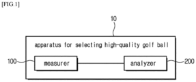
- FIG. 1 is a block diagram schematically showing the configuration of an apparatus for selecting a high-quality golf ball according to an embodiment of the disclosure.
- the apparatus for selecting a high-quality golf ball may include a measurer 100 and an analyzer 200.
- the measurer 100 may transmit a signal toward a measurement target golf ball, and receive a signal reflected from or transmitted through the golf ball.
- the signal may be transmitted and received with respect to a plurality of measurement sides of the golf ball.
- the measurement side may be perpendicular to the direction of signal to be transmitted.
- the signal may be electromagnetic waves, and may for example include, but not limited to, a radio frequency (RF) electromagnetic signal.
- RF radio frequency
- the measurer 100 receives first electromagnetic waves reflected or transmitted after rotating the measurement target golf ball at an arbitrary angle, and receives second electromagnetic waves reflected or transmitted after rotating the measurement target golf ball at an arbitrary angle. In this way, the measurement may be repeated for the plurality of measurement sides by rotating the golf ball and transmitting and receiving the electromagnetic waves.
- the measurer 100 may include a rotary supporter rotatably supporting a measurement target golf ball, an electromagnetic wave transmitting antenna 110 disposed at a first side of the golf ball and configured to transmit electromagnetic waves toward the golf ball, and an electromagnetic wave receiving antenna 120 disposed at a second side of the golf ball and configured to receive the electromagnetic waves transmitted from the electromagnetic wave transmitting antenna 110.
- the electromagnetic signal transmitted from the electromagnetic wave transmitting antenna 110 at the first side of the golf ball is received in the electromagnetic wave receiving antenna 120 at the second side of the golf ball, thereby receiving the electronic signal transmitted through the golf ball.
- the measurer 100 may include a rotary supporter rotatably supporting a measurement target golf ball, and an electromagnetic wave transceiving antenna 1120 disposed at a first side of the golf ball and configured to transmit electromagnetic waves toward the golf ball and receive the electromagnetic waves reflected from the golf ball.
- the electromagnetic signal transmitted from the electromagnetic wave transceiving antenna 1120 disposed at the first side of the golf ball is reflected from the golf ball and received in the electromagnetic wave transceiving antenna 1120.
- the analyzer 200 analyzes signals received with respect to a plurality of measurement sides while rotating the golf ball, thereby selecting a high-quality golf ball. For example, if the core in the golf ball has a uniform spherical shape, and the core, inner shell, and outer shell of the golf ball have a symmetric structure, the signals received while rotating the golf ball may have high uniformity. In other words, the electromagnetic waves reflected from or transmitted through the plurality of measurement sides are highly similar in magnitude and phase. It is estimated that the greater the difference in magnitude and phase between the electromagnetic waves reflected from or transmitted through the measurement sides, the greater the non-uniformity inside the golf ball. Therefore, the analyzer 200 according to the disclosure selects a high-quality golf ball, which has a uniform internal medium and is close to symmetry, based on the uniformity of the signals received while the rotary supporter rotates the golf ball.
- the analyzer 200 may be configured as software installed in a computer including a computing device and a storage device, or a smart device such as a smartphone.
- the analyzer 200 may use a deep learning technique to estimate the eccentricity or imbalance of the medium inside the golf ball.
- the analyzer 200 may use the deep learning technique to grade the eccentricity or imbalance of the golf ball, or use a preset criterion to determine a defect.
- FIG. 2 shows perspective and lateral views of an apparatus for selecting a high-quality golf ball according to an embodiment of the disclosure
- FIG. 3 shows an alternative example of FIG. 2 .
- the measurer 100 in the apparatus for selecting a high-quality golf ball may include a rotary supporter and two antennas 110 and 120.
- the rotary supporter may include a golf ball supporter 130 and a rotation unit 135.
- the golf ball supporter 130 supports the measurement target golf ball to be vertically spaced apart from the ground. As shown therein, the golf ball supporter 130 may be shaped like a bar extended vertically upwards from the ground, and includes an upper end on which a golf ball is seated.
- the rotation unit 135 rotates the golf ball supporter 130 with respect to a vertical axis. As the golf ball supporter 130 is rotated by the rotation unit 135, the measurement side of the golf ball, to which the electromagnetic wave transmitting antenna 110 transmits the electromagnetic waves, is changed. In this case, the rotation unit 135 may rotate the golf ball by a predetermined angle.
- the rotation unit 135 may include a motor for rotating the golf ball supporter 130.
- the measurer 100 of FIG. 2 may additionally include antenna supporters 115 and 125.
- the antenna supporters 115 and 125 include a first antenna supporter 115 and a second antenna supporter 125 which are spaced apart from the golf ball supporter 130 and respectively support the electromagnetic wave transmitting antenna 110 and the electromagnetic wave receiving antenna 120 to be located on the same horizontal plane as the golf ball supported by the golf ball supporter 130.
- the measurer 100 of FIG. 2 may further include a base 160 to support the golf ball supporter 130 and the antenna supporters 115 and 125 on one side thereof.
- the base 160 is formed with sliding holes (not shown) on one side thereof between the antenna supporters 115 and 125 and the golf ball supporter 130 so that the antenna supporters 115 and 125 can be slidably coupled to the sliding holes. Therefore, the antenna supporters 115 and 125 are adjustable in distance from the golf ball supporter 130.
- the golf ball supporter 130 and the antenna supporters 115 and 125 are vertically extendable so that a target to be supported can be adjusted in vertical distance from the base 160.
- An absorber 162 for absorbing electromagnetic waves may be attached or applied to one side of the base 160.
- the absorber 162 may contain, but is not necessarily limited to, ferrite.
- the absorber 162 may absorb the electromagnetic waves transmitted from the electromagnetic wave transmitting antenna 110 and diffusely reflected from the golf ball supporter 130 or the antenna supporters 115 and 125, thereby preventing the electromagnetic wave receiving antenna 120 from receiving noise. As shown therein, the absorber 162 may also be attached or applied to the antenna supporters 115 and 125.
- the electromagnetic wave transmitting antenna 110 and the electromagnetic wave receiving antenna 120 may be connected to a detector 140.
- the detector 140 generates the electromagnetic waves, transmits and receives the electromagnetic waves through the electromagnetic wave transmitting antenna 110 and the electromagnetic wave receiving antenna 120, and outputs and detects the magnitude and phase of the received electromagnetic waves.
- the detector 140 may be configured in various forms.
- the detector 140 may include a transmitting circuit 1413 and a receiving circuit 1414, may include a network analyzer 1420, or may include a signal generator 1430 and a spectrum analyzer 1432, but is not limited thereto.
- the electromagnetic wave transmitting antenna 110 and the electromagnetic wave receiving antenna 120 are connected to the electromagnetic wave transmitting side and the electromagnetic wave receiving side of the network analyzer 1420, respectively.
- the detector 140 includes the signal generator 1430 and the spectrum analyzer 1432, the electromagnetic wave transmitting antenna 110 is connected to the signal generator 1430 and the electromagnetic wave receiving antenna 120 is connected to the spectrum analyzer 1432.
- the detector 140 may be connected to the analyzer 200 and transmit information about the magnitude and phase of the detected electromagnetic waves to the analyzer 200.
- FIG. 3 shows an alternative example of the measurer 100 shown in FIG. 2 .
- the electromagnetic wave transceiving antenna 1120 into which the electromagnetic wave transmitting antenna 110 and the electromagnetic wave receiving antenna 120 are integrated, is provided.
- the rotary supporter including the golf ball supporter 130 and the rotation unit 135 has the same configuration as described above.
- An antenna supporter 1125 supports the electromagnetic wave transceiving antenna 1120.
- the antenna supporter 1125 is spaced apart from the golf ball supporter 130, and supports the electromagnetic wave transceiving antenna 1120 on the same horizontal surface as the measurement target golf ball supported by the golf ball supporter 130.
- the antenna supporter 1125 is slidably provided with respect to the golf ball supporter 130, and thus adjustable in distance from the golf ball supporter 130.
- the electromagnetic wave transceiving antenna 1120 may be connected to the detector 140 and receive only the reflected electromagnetic waves from the plurality of measurement sides of the measurement target golf ball.
- the detector 140 is connected to the electromagnetic wave transceiving antenna 1120, transmits and receives the electromagnetic waves, detects the magnitude and phase of the received electromagnetic waves, and transmits a detection result to the analyzer 200.
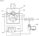
- FIG. 4 is a view showing an apparatus for selecting a high-quality golf ball according to another embodiment of the disclosure
- FIG. 5 is a perspective view showing details of a rotary supporter of FIG. 4
- FIGS. 6 and 7 are views respectively showing alternative examples of a detector shown in FIG. 4
- FIG. 8 shows an alternative example of FIG. 4
- FIGS. 9 and 10 are views respectively showing alternative examples of a detector shown in FIG. 8 .
- the measurer 100 may include the rotary supporter, the electromagnetic wave transmitting antenna 110, and the electromagnetic wave receiving antenna 120.
- the rotary supporter shown in FIG. 5 supports and rotates the golf ball, thereby changing the posture of the golf ball.
- the rotary supporter may include a first rotation supporting plate 170, a first motor 171 for rotating the first rotation supporting plate 170, a second rotation supporting plate 172, and a second motor 173 for rotating the second rotation supporting plate 172.
- the rotary supporter may further include a roll bar 174.
- the first rotation supporting plate 170 and the first motor 171 may be supported by and fastened to a frame 180 having a hexahedral structure.
- the first rotation supporting plate 170 may be shaped like a disc or a cylinder, have an axis disposed in a horizontal direction parallel to the ground, and, as shown therein, use its lateral side to support a lateral side, i.e., a first point of the golf ball.
- a motor shaft of the first motor 171 is connected to the central axis of the first rotation supporting plate 170, so that the first rotation supporting plate 170 can rotate as the first motor 171 is driven. Therefore, the rotation of the first rotation supporting plate 170 makes the golf ball being supported at the first point be rotated, thereby changing the posture of the golf ball.
- the second rotation supporting plate 172 and the second motor 173 may support a lateral side, i.e., a second point of the golf ball in the same manner as the first rotation supporting plate 170 and the first motor 171.
- the first rotation supporting plate 170 and the second rotation supporting plate 172 may be disposed to respectively support the golf ball in perpendicular direction from the center of the golf ball when we see from top to bottom, so the first point and the second point at which the golf ball is supported may be on the lines that pass through the center of the golf ball and are perpendicular to each other.
- the golf ball may rotate in two directions perpendicular to each other. Therefore, the posture of the golf ball may be variously changed so that all the sides of the golf ball can face the stationarily disposed electromagnetic wave transmitting or receiving antenna 110 or 120.
- the roll bar 174 refers to a bar which is freely rotatable at opposite sides thereof, and supports the third point of the golf ball at a middle outer surface thereof.
- the third point may be located in the middle of the opposite side to the first and second points with respect to the center of the golf ball when viewed downwards from above, and support the lower side of the golf ball when viewed from lateral sides.
- a pair of holding bars 175 may be extended inwards from the frame 180, so that the opposite ends of the roll bar 174 can be free-rotatably coupled to both ends of the holding bar 175.
- first rotation supporting plate 170 the second rotation supporting plate 172
- the roll bar 174 can freely rotate when the first rotation supporting plate 170 or the second rotation supporting plate 172 is driven to rotate by the motor, thereby stably supporting the golf ball.
- the electromagnetic wave transmitting antenna 110 may be disposed at the first side of the golf ball and transmit a signal toward the golf ball.
- a seating groove 182 may be formed to easily fix the electromagnetic wave transmitting antenna 110.
- the electromagnetic wave receiving antenna 120 may be disposed at the second side of the golf ball and receive the signal transmitted from the electromagnetic wave transmitting antenna 110 toward the golf ball and transmitted through the golf ball.
- a predetermined circuit board i.e., a control board 190 may include a micro controller unit (MCU) 1411, a motor controller 1412 controlling the operation of the first motor 171 or the second motor 173, and the detector 140.
- MCU micro controller unit
- motor controller 1412 controlling the operation of the first motor 171 or the second motor 173, and the detector 140.
- the detector 140 may include the transmitting circuit 1413 for generating a signal to be transmitted from the electromagnetic wave transmitting antenna 110 and transmitting the signal to the electromagnetic wave transmitting antenna 110, and the receiving circuit 1414 for receiving the signal received in the electromagnetic wave receiving antenna 120 and processing information about the magnitude and phase of the signal.
- a communicator 1415 may transmit the processed signal from the receiving circuit 1414 to an external device, i.e., the analyzer 200 including a smart phone, a smart pad, and the like terminal, a personal computer (PC), etc.
- the communicator 1415 may transmit data by a wire or wirelessly, and FIG. 4 shows a structure of using a Bluetooth low energy (BLE) signal to transmit the signal processed by the receiving circuit 1414 to the smart phone or the like terminal.
- the analyzer 200 receives and analyzes the signal to determine the uniformity of the golf ball and display a selection result on a screen of a display.
- FIG. 6 shows an alternative example of the detector 140 in FIG. 4 .
- the network analyzer 1420 that generates a signal to be transmitted from the electromagnetic wave transmitting antenna 110, transmits the signal to the electromagnetic wave transmitting antenna 110, and processes the signal received in the electromagnetic wave receiving antenna 120 is used as the foregoing transceiving circuit.
- the information about the magnitude and phase of the processed signal may be transmitted from the network analyzer 1420 to the analyzer 200 in real time.
- the PC is illustrated as the analyzer 200.
- the operation of the motor controller 1412 for driving the first motor 171 or the second motor 173 may be controlled by a control command of the PC.
- FIG. 7 shows another alternative example of the detector in FIG. 4 .
- the signal generator 1430 that generates a signal to be transmitted from the electromagnetic wave transmitting antenna 110 and transmits the signal to the electromagnetic wave transmitting antenna 110
- the spectrum analyzer 1432 that receives and processes the signal received in the electromagnetic wave receiving antenna 120 are used as the transceiving circuit.
- the information about the magnitude and phase of the signal processed by the spectrum analyzer 1432 may be transmitted to the analyzer 200 in real time.
- the PC is illustrated as the analyzer 200.
- the operation of the motor controller 1412 for driving the first motor 171 or the second motor 173 may be controlled by a control command of the PC.
- FIG. 8 shows an alternative example of the measurer 100 shown in FIG. 4 .
- descriptions will be made focusing on difference from the foregoing embodiments.
- the electromagnetic wave transceiving antenna 1120 into which the electromagnetic wave transmitting antenna 110 and the electromagnetic wave receiving antenna 120 are integrated, is provided.
- the apparatus for selecting a high-quality golf ball may include the rotary supporter, the electromagnetic wave transceiving antenna 1120, and the analyzer 200.
- the electromagnetic wave transmitting antenna 110 disposed at the first side of the golf ball and the electromagnetic wave receiving antenna 120 disposed at the second side of the golf ball are used in such a manner that the signal transmitted from the electromagnetic wave transmitting antenna 110 and transmitted through the golf ball is received in the electromagnetic wave receiving antenna 120, thereby selecting a high-quality golf ball based on the received signal.
- the electromagnetic wave transceiving antenna 1120 according to this embodiment is placed at the first side of the golf ball, transmits the signal toward the golf ball, and receives a signal reflected from the golf ball.
- the control board 190 may include a MCU1411, the motor controller 1412 for controlling the operation of the motor, the transmitting circuit 1413 for generating a signal to be transmitted from the electromagnetic wave transceiving antenna 1120 and transmitting the signal the electromagnetic wave transceiving antenna 1120, the receiving circuit 1414 for processing the signal received from the electromagnetic wave transceiving antenna 1120, and the communicator 1415 for transmitting the processed signal from the receiving circuit 1414 to the analyzer 200 provided as the external terminal or the PC.
- the motor controller 1412 for controlling the operation of the motor
- the transmitting circuit 1413 for generating a signal to be transmitted from the electromagnetic wave transceiving antenna 1120 and transmitting the signal the electromagnetic wave transceiving antenna 1120
- the receiving circuit 1414 for processing the signal received from the electromagnetic wave transceiving antenna 1120
- the communicator 1415 for transmitting the processed signal from the receiving circuit 1414 to the analyzer 200 provided as the external terminal or the PC.
- the network analyzer 1420 that generates a signal to be transmitted from the electromagnetic wave transceiving antenna 1120, transmits the signal to the electromagnetic wave transceiving antenna 1120, and processes the signal received in the electromagnetic wave transceiving antenna 1120 may be used as the foregoing transceiving circuit.
- the information about the magnitude and phase of the processed signal may be transmitted from the network analyzer 1420 to the analyzer 200 in real time, so that a selection result can be displayed on a monitor.
- the operation of the motor controller 1412 for driving the first motor 171 or the second motor 173 may be controlled by a control command of the PC.
- the signal generator 1430 that generates a signal to be transmitted from the electromagnetic wave transceiving antenna 1120 and transmits the signal to the electromagnetic wave transceiving antenna 1120
- the spectrum analyzer 1432 that receives and processes the signal received in the electromagnetic wave transceiving antenna 1120 may be used as the transceiving circuit.
- the information about the magnitude and phase of the signal processed by the spectrum analyzer 1432 may be transmitted to the analyzer 200 in real time, so that a selection result of the analyzer 200 can be displayed on the monitor.
- the operation of the motor controller 1412 for driving the first motor 171 or the second motor 173 may be controlled by a control command of the PC.
- the detector 140 may additionally include a circulator 1440 for distinguishing between a transmitted signal and a received signal while the signal is being transmitted and received.
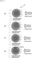
- FIG. 11 is a view illustrating electromagnetic signals transmitted through and reflected from (a) a golf ball with internal and external symmetry, (b) a golf ball with an eccentric core, (c) a golf ball with an asymmetric and imbalanced core, and (d) a golf ball with a damaged cover, and FIG. 12 is a cross-sectional view for explaining the eccentricity of a golf ball.
- the golf ball may include a core, an inner shell, and an outer shell which are different in material from one another.
- the golf ball may include a core made of rubber, an inner shell layer made of plastic, and an outer shall layer made of thermosetting polyurethane, thermoplastic polyurethane, or ionomer plastic.
- various materials have been developed and applied to the golf ball in order to increase the driving distance of the golf ball, and complex materials for each manufacturer may be mixed into the golf ball.
- the electromagnetic waves transmitted from the electromagnetic wave transmitting antenna 110 or the electromagnetic wave transceiving antenna 1120 are incident to the golf ball, the incident waves are scattered and transmitted on the interface between different materials that constitute the golf ball.
- the reflected waves may be returned to the electromagnetic wave transceiving antenna 1120, and the transmitted waves may be received in the electromagnetic wave receiving antenna 120 on the opposite side.
- the reflection and transmission characteristics of the electromagnetic waves are very sensitive to the dielectric constant of the medium in the golf ball, and therefore the magnitude and phase characteristics of the reflected or transmitted electromagnetic waves may be varied depending on the uniformity of the medium inside the golf ball.
- the reflection or transmission characteristics measured while rotating the golf ball may be uniform.
- the core and outer shell of the golf ball are different in physical properties from each other, and the diameter of the golf ball is approximately 42 mm.
- the measurement may be performed by selecting a frequency at which reactivity is high.
- the electromagnetic waves reflected or transmitted for each measurement side are different in characteristics.
- the electromagnetic waves reflected or transmitted for each measurement side may be different in characteristics. Because the external damage is relatively very small compared to the size of the golf ball, the measurement may be performed at a frequency higher than that of when the balance and eccentricity in the golf ball are detected.
- the internal uniformity of the golf ball may be quantified and evaluated based on the characteristics of the electromagnetic waves measured while the golf ball is rotated by the rotary supporter (e.g., based on the uniformity of the magnitude and phase of the reflected or transmitted signal).
- the eccentricity may be expressed with a distance r from the center P1 of the golf ball to the center P2 of the core with respect to the radius R of the golf ball as shown in the Equation 1.
- Eccentricity ⁇ r the distance from the center of the golf ball to the center of the core / R the radius of the golf ball
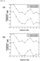
- FIGS. 13 and 14 are graphs showing the results of measuring electromagnetic wave transmission characteristics by an apparatus for selecting a high-quality golf ball according to the disclosure
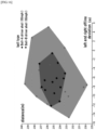
- FIG. 15 is a graph showing the results of driver shots at a switching speed of 115mph with respect to a ball selected in (a) of FIG. 14 and a ball selected in (b) of FIG. 14
- FIG. 16 is a graph showing the results of driver shots at a switching speed of 95mph with respect to a ball selected in (a) of FIG. 14 and a ball selected in (b) of FIG. 14
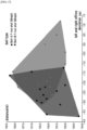
- FIG. 17 is a graph showing the results of 7-iron shots at a switching speed of 85mph with respect to a ball selected in (a) of FIG. 14 and a ball selected in (b) of FIG. 14
- FIG. 18 is a graph showing the results of pitching wedge shots at a switching speed of 115mph with respect to a ball selected in (a) of FIG. 14 and a ball selected in (b) of FIG. 14 .
- FIG. 13 shows the magnitude at the frequency of the electromagnetic waves received according to the eccentricity of a defective golf ball, and (b) shows the phase at the frequency of the electromagnetic waves received according to the eccentricity of the defective golf ball.
- both the magnitude and phase of the transmitted electromagnetic waves were varied depending on change in eccentricity. As the eccentricity increased from 0 to 0.2, the transmission gradually increased at a frequency lower than the frequency F3, but gradually decreased at a frequency higher than the frequency F3.
- the magnitude and phase of electromagnetic waves were sensitively varied between certain frequencies F2 and F5 depending on the degree of eccentricity. Therefore, the degree of imbalanced symmetricity such as the eccentricity inside the golf ball may be estimated based on the transmission and reflection characteristics of the electromagnetic waves.
- the eccentricity and the balance may be quantified by applying a set of data about the eccentricity and the transmission and reflection characteristics to a deep learning technique, and it is thus possible to automatically select a defective golf ball.
- FIG. 14 shows results of measuring the electromagnetic wave transmission characteristics of specific brand golf ball available on the market an apparatus for selecting a high-quality golf ball according to the disclosure.
- the maximum transmission coefficients of the golf balls Ball-A and Ball-B were almost the same, but the minimum transmission coefficients of the golf ball Ball-B was lower than that of the golf ball Ball-A by about 1 dB at all measurement frequencies.
- a swing robot of Korea institute of golf and sports was used in a test. Because the swing robot can repeat swing motions with the same speed and mechanism unlike a human, the same spot on a club face may be hit every swing.
- the flight trajectory of the golf ball was analyzed using the Foresight's GC Quad launch monitor.
- the GC Quad launch monitor can provide precise flight trajectory results only based on the characteristics of the golf ball because external factors affecting the flight of the golf ball, such as wind and humidity are excluded.
- the difference between the golf balls Ball-A and Ball-B was clear (see FIGS. 15 and 16 ).
- the golf ball Ball-A with a lower SOD showed that the driving distances had a smaller deviation.
- the left and right offline deviation of the golf ball Ball-A was much lower than that of the golf ball Ball-B.
- the golf ball Ball-B with a higher SOD showed that its offline deviation was 2.4 times higher than that of the golf ball Ball-A.
- the test results of the 7-iron and pitching wedge shots are also shown in FIGS. 17 and 18 , and it will be understood that the golf ball Ball-A with a lower SOD showed better consistency than that of the golf ball Ball-B with a higher SOD.
Landscapes
- Engineering & Computer Science (AREA)
- Physics & Mathematics (AREA)
- Remote Sensing (AREA)
- General Physics & Mathematics (AREA)
- Radar, Positioning & Navigation (AREA)
- Life Sciences & Earth Sciences (AREA)
- Health & Medical Sciences (AREA)
- General Health & Medical Sciences (AREA)
- Electromagnetism (AREA)
- Chemical & Material Sciences (AREA)
- Computer Networks & Wireless Communication (AREA)
- Pathology (AREA)
- Immunology (AREA)
- Biochemistry (AREA)
- Analytical Chemistry (AREA)
- Physical Education & Sports Medicine (AREA)
- Biophysics (AREA)
- Evolutionary Computation (AREA)
- Artificial Intelligence (AREA)
- Environmental & Geological Engineering (AREA)
- Geology (AREA)
- General Life Sciences & Earth Sciences (AREA)
- Geophysics (AREA)
- Food Science & Technology (AREA)
- Medicinal Chemistry (AREA)
- Radar Systems Or Details Thereof (AREA)
- Geophysics And Detection Of Objects (AREA)
Applications Claiming Priority (3)
| Application Number | Priority Date | Filing Date | Title |
|---|---|---|---|
| KR1020210082339A KR102569745B1 (ko) | 2021-06-24 | 2021-06-24 | 골프공의 균형성 분석 장치 |
| KR1020210128704A KR102706945B1 (ko) | 2021-09-29 | 2021-09-29 | 골프공 선별 장치 |
| PCT/KR2022/008762 WO2022270864A1 (ko) | 2021-06-24 | 2022-06-21 | 골프공 선별 장치 |
Publications (3)
| Publication Number | Publication Date |
|---|---|
| EP4335521A1 true EP4335521A1 (de) | 2024-03-13 |
| EP4335521A4 EP4335521A4 (de) | 2024-10-23 |
| EP4335521B1 EP4335521B1 (de) | 2025-12-10 |
Family
ID=84545573
Family Applications (1)
| Application Number | Title | Priority Date | Filing Date |
|---|---|---|---|
| EP22828711.6A Active EP4335521B1 (de) | 2021-06-24 | 2022-06-21 | Vorrichtung zum sortieren von golfbällen |
Country Status (5)
| Country | Link |
|---|---|
| US (1) | US12296231B2 (de) |
| EP (1) | EP4335521B1 (de) |
| JP (1) | JP7505828B2 (de) |
| CN (1) | CN116324399B (de) |
| WO (1) | WO2022270864A1 (de) |
Families Citing this family (2)
| Publication number | Priority date | Publication date | Assignee | Title |
|---|---|---|---|---|
| WO2022270864A1 (ko) * | 2021-06-24 | 2022-12-29 | (주)엠텔리 | 골프공 선별 장치 |
| KR102660995B1 (ko) * | 2023-09-25 | 2024-04-25 | (주)엠텔리 | 골프공 검사 장치 |
Family Cites Families (29)
| Publication number | Priority date | Publication date | Assignee | Title |
|---|---|---|---|---|
| JPS5563758A (en) * | 1978-11-08 | 1980-05-14 | Sumitomo Rubber Ind Ltd | Method of discriminating type of golf ball |
| DE3926684A1 (de) * | 1989-08-12 | 1991-02-14 | Guenter Prof Dr Hermann | System zum auffinden gespielter golfbaelle im gelaende |
| JPH04364402A (ja) * | 1991-06-11 | 1992-12-16 | Toshiba Corp | 偏心検査方法 |
| JPH06126015A (ja) * | 1992-01-04 | 1994-05-10 | Hiroshi Imanishi | ゴルフ球位置検索システム |
| JPH06237090A (ja) | 1993-02-08 | 1994-08-23 | Hitachi Eng Co Ltd | 電波暗室 |
| FR2708472A1 (fr) * | 1993-05-03 | 1995-02-10 | Veillerot Christiane | Dispositif additionnel, électronique et électromagnétique, ajouté aux balles de golf pour les localiser et les identifier. |
| JP2840205B2 (ja) * | 1995-02-24 | 1998-12-24 | 日ノ出エンジニアリング株式会社 | バリ付きゴルフボールの姿勢修正装置及びそれを用いたバリ取り機 |
| JPH08271446A (ja) | 1995-03-30 | 1996-10-18 | Ntn Corp | 球体の外観検査方法および装置 |
| KR0176661B1 (ko) * | 1995-12-28 | 1999-05-15 | 김광호 | 납땜부 검사방법 및 검사장치 |
| JPH1137881A (ja) * | 1997-07-17 | 1999-02-12 | Sumitomo Rubber Ind Ltd | 偏重心の検出装置及び検出方法 |
| SE518997C2 (sv) * | 2001-04-02 | 2002-12-17 | Impressonic Ab | Förfarande och anordning för att detektera skada i material eller föremål |
| US6757353B2 (en) * | 2002-08-28 | 2004-06-29 | Acushnet Company | Golf ball inspection using metal markers |
| US7116413B2 (en) | 2002-09-13 | 2006-10-03 | Kla-Tencor Corporation | Inspection system for integrated applications |
| JP2004230325A (ja) * | 2003-01-31 | 2004-08-19 | Kazuya Shiraiwa | ゴルフボール選別方法および装置 |
| JP2005205091A (ja) * | 2004-01-26 | 2005-08-04 | Bridgestone Sports Co Ltd | ゴルフボール |
| JP5917218B2 (ja) * | 2012-03-19 | 2016-05-11 | 八光オートメーション株式会社 | 内部欠陥検査装置及び内部欠陥の検査方法 |
| KR101358177B1 (ko) | 2012-04-03 | 2014-02-07 | 양서일 | 골프공 검사장치 |
| WO2013172015A1 (ja) * | 2012-05-16 | 2013-11-21 | 横浜ゴム株式会社 | 球技用ボール |
| JP6290036B2 (ja) * | 2013-09-25 | 2018-03-07 | 株式会社東芝 | 検査装置及び検査システム |
| KR20170136906A (ko) * | 2016-06-02 | 2017-12-12 | 고성우 | 구체의 크랙 검사방법 및 장치 |
| JP2018072252A (ja) * | 2016-11-01 | 2018-05-10 | 倉敷紡績株式会社 | 球体物の表面の検査装置および検査方法 |
| KR102012601B1 (ko) | 2018-11-22 | 2019-08-20 | 주식회사 담스테크 | 전자기파의 생체 영향 분석장치 |
| US11752396B1 (en) * | 2020-02-19 | 2023-09-12 | Topgolf Callaway Brands Corp. | Method and system utilizing imaging analysis for golf balls |
| US11058924B1 (en) | 2020-02-19 | 2021-07-13 | Callaway Golf Company | Method and system utilizing imaging analysis for golf balls |
| US20220184463A1 (en) * | 2020-12-10 | 2022-06-16 | Michael Ganson | Sports ball system for monitoring ball characteristics and method therefor |
| WO2022270864A1 (ko) * | 2021-06-24 | 2022-12-29 | (주)엠텔리 | 골프공 선별 장치 |
| US11543241B1 (en) * | 2021-07-07 | 2023-01-03 | Acushnet Company | Multi-energy x-ray system and method for golf ball inspection |
| US11668560B1 (en) * | 2021-07-19 | 2023-06-06 | Acushnet Company | X-ray system and method for golf ball inspection |
| JP2025063758A (ja) * | 2023-10-04 | 2025-04-16 | 株式会社デンソー | 内燃機関用のスパークプラグ |
-
2022
- 2022-06-21 WO PCT/KR2022/008762 patent/WO2022270864A1/ko not_active Ceased
- 2022-06-21 EP EP22828711.6A patent/EP4335521B1/de active Active
- 2022-06-21 JP JP2023506290A patent/JP7505828B2/ja active Active
- 2022-06-21 CN CN202280006154.4A patent/CN116324399B/zh active Active
- 2022-06-21 US US17/907,609 patent/US12296231B2/en active Active
Also Published As
| Publication number | Publication date |
|---|---|
| CN116324399B (zh) | 2026-04-10 |
| JP2023536867A (ja) | 2023-08-30 |
| CN116324399A (zh) | 2023-06-23 |
| WO2022270864A1 (ko) | 2022-12-29 |
| US12296231B2 (en) | 2025-05-13 |
| EP4335521B1 (de) | 2025-12-10 |
| US20240207693A1 (en) | 2024-06-27 |
| EP4335521A4 (de) | 2024-10-23 |
| JP7505828B2 (ja) | 2024-06-25 |
Similar Documents
| Publication | Publication Date | Title |
|---|---|---|
| EP4335521A1 (de) | Vorrichtung zum sortieren von golfbällen | |
| KR102636526B1 (ko) | 볼 마킹을 이용하여 스핀 측정을 결정하기 위한 시스템 및 방법 | |
| US8251841B2 (en) | Method and apparatus for analyzing a golf swing | |
| JP4865735B2 (ja) | スポーツボールの回転パラメータの決定 | |
| US8070620B2 (en) | Method and apparatus for measuring golf green speeds | |
| US20240216777A1 (en) | Launch monitor | |
| WO2014110398A1 (en) | Ball spin rate measurement | |
| US9254427B2 (en) | Active golf tee | |
| KR102569745B1 (ko) | 골프공의 균형성 분석 장치 | |
| US9320951B2 (en) | Active golf tee | |
| KR20170136906A (ko) | 구체의 크랙 검사방법 및 장치 | |
| KR101772521B1 (ko) | 구기용 볼 | |
| US7144338B2 (en) | Golf ball with varying land surfaces | |
| JP5585050B2 (ja) | ゴルフスウィング計測方法、ゴルフクラブの選定方法及びゴルフスウィング計測装置 | |
| KR102706945B1 (ko) | 골프공 선별 장치 | |
| CN109257118B (zh) | 无线产品的收发效能验证设备及其操作方法 | |
| US9248354B2 (en) | Active golf tee | |
| US11731007B2 (en) | Wireless billiard ball device | |
| US12409373B1 (en) | Golf club head impact location based on 3D magnetic field readings | |
| CN117244804B (zh) | 一种球类质量检测仪 |
Legal Events
| Date | Code | Title | Description |
|---|---|---|---|
| STAA | Information on the status of an ep patent application or granted ep patent |
Free format text: STATUS: THE INTERNATIONAL PUBLICATION HAS BEEN MADE |
|
| PUAI | Public reference made under article 153(3) epc to a published international application that has entered the european phase |
Free format text: ORIGINAL CODE: 0009012 |
|
| STAA | Information on the status of an ep patent application or granted ep patent |
Free format text: STATUS: REQUEST FOR EXAMINATION WAS MADE |
|
| 17P | Request for examination filed |
Effective date: 20231205 |
|
| AK | Designated contracting states |
Kind code of ref document: A1 Designated state(s): AL AT BE BG CH CY CZ DE DK EE ES FI FR GB GR HR HU IE IS IT LI LT LU LV MC MK MT NL NO PL PT RO RS SE SI SK SM TR |
|
| DAV | Request for validation of the european patent (deleted) | ||
| DAX | Request for extension of the european patent (deleted) | ||
| A4 | Supplementary search report drawn up and despatched |
Effective date: 20240925 |
|
| RIC1 | Information provided on ipc code assigned before grant |
Ipc: G01S 13/00 20060101ALN20240919BHEP Ipc: G01B 11/24 20060101ALN20240919BHEP Ipc: A63B 24/00 20060101ALN20240919BHEP Ipc: G01N 33/00 20060101ALI20240919BHEP Ipc: G01N 21/892 20060101ALI20240919BHEP Ipc: A63B 102/32 20150101ALI20240919BHEP Ipc: G01N 3/08 20060101ALI20240919BHEP Ipc: A63B 37/00 20060101ALI20240919BHEP Ipc: G01N 21/95 20060101ALI20240919BHEP Ipc: G01N 21/84 20060101ALI20240919BHEP Ipc: G01N 21/25 20060101ALI20240919BHEP Ipc: G01S 13/88 20060101ALI20240919BHEP Ipc: G01N 29/46 20060101ALI20240919BHEP Ipc: G01V 3/12 20060101ALI20240919BHEP Ipc: G01N 29/04 20060101ALI20240919BHEP Ipc: G01S 13/89 20060101ALI20240919BHEP Ipc: G01S 7/41 20060101ALI20240919BHEP Ipc: G01N 22/02 20060101ALI20240919BHEP Ipc: G01B 5/00 20060101ALI20240919BHEP Ipc: A63B 47/00 20060101AFI20240919BHEP |
|
| RIC1 | Information provided on ipc code assigned before grant |
Ipc: A63B 47/00 20060101AFI20250703BHEP Ipc: G01B 5/00 20060101ALI20250703BHEP Ipc: G01N 22/02 20060101ALI20250703BHEP Ipc: G01S 7/41 20060101ALI20250703BHEP Ipc: G01S 13/89 20060101ALI20250703BHEP Ipc: G01N 29/04 20060101ALI20250703BHEP Ipc: G01V 3/12 20060101ALI20250703BHEP Ipc: G01N 29/46 20060101ALI20250703BHEP Ipc: G01S 13/88 20060101ALI20250703BHEP Ipc: G01N 21/25 20060101ALI20250703BHEP Ipc: G01N 21/84 20060101ALI20250703BHEP Ipc: G01N 21/95 20060101ALI20250703BHEP Ipc: A63B 37/00 20060101ALI20250703BHEP Ipc: G01N 3/08 20060101ALI20250703BHEP Ipc: A63B 102/32 20150101ALI20250703BHEP Ipc: G01N 21/892 20060101ALI20250703BHEP Ipc: G01N 33/00 20060101ALI20250703BHEP Ipc: A63B 24/00 20060101ALN20250703BHEP Ipc: G01B 11/24 20060101ALN20250703BHEP Ipc: G01S 13/00 20060101ALN20250703BHEP |
|
| GRAP | Despatch of communication of intention to grant a patent |
Free format text: ORIGINAL CODE: EPIDOSNIGR1 |
|
| STAA | Information on the status of an ep patent application or granted ep patent |
Free format text: STATUS: GRANT OF PATENT IS INTENDED |
|
| RIC1 | Information provided on ipc code assigned before grant |
Ipc: A63B 47/00 20060101AFI20250902BHEP Ipc: G01B 5/00 20060101ALI20250902BHEP Ipc: G01N 22/02 20060101ALI20250902BHEP Ipc: G01S 7/41 20060101ALI20250902BHEP Ipc: G01S 13/89 20060101ALI20250902BHEP Ipc: G01N 29/04 20060101ALI20250902BHEP Ipc: G01V 3/12 20060101ALI20250902BHEP Ipc: G01N 29/46 20060101ALI20250902BHEP Ipc: G01S 13/88 20060101ALI20250902BHEP Ipc: G01N 21/25 20060101ALI20250902BHEP Ipc: G01N 21/84 20060101ALI20250902BHEP Ipc: G01N 21/95 20060101ALI20250902BHEP Ipc: A63B 37/00 20060101ALI20250902BHEP Ipc: G01N 3/08 20060101ALI20250902BHEP Ipc: A63B 102/32 20150101ALI20250902BHEP Ipc: G01N 21/892 20060101ALI20250902BHEP Ipc: G01N 33/00 20060101ALI20250902BHEP Ipc: A63B 24/00 20060101ALN20250902BHEP Ipc: G01B 11/24 20060101ALN20250902BHEP Ipc: G01S 13/00 20060101ALN20250902BHEP |
|
| INTG | Intention to grant announced |
Effective date: 20250910 |
|
| GRAS | Grant fee paid |
Free format text: ORIGINAL CODE: EPIDOSNIGR3 |
|
| GRAA | (expected) grant |
Free format text: ORIGINAL CODE: 0009210 |
|
| STAA | Information on the status of an ep patent application or granted ep patent |
Free format text: STATUS: THE PATENT HAS BEEN GRANTED |
|
| AK | Designated contracting states |
Kind code of ref document: B1 Designated state(s): AL AT BE BG CH CY CZ DE DK EE ES FI FR GB GR HR HU IE IS IT LI LT LU LV MC MK MT NL NO PL PT RO RS SE SI SK SM TR |
|
| REG | Reference to a national code |
Ref country code: CH Ref legal event code: F10 Free format text: ST27 STATUS EVENT CODE: U-0-0-F10-F00 (AS PROVIDED BY THE NATIONAL OFFICE) Effective date: 20251210 Ref country code: GB Ref legal event code: FG4D |
|
| REG | Reference to a national code |
Ref country code: DE Ref legal event code: R096 Ref document number: 602022026743 Country of ref document: DE |
|
| REG | Reference to a national code |
Ref country code: IE Ref legal event code: FG4D |
|
| P01 | Opt-out of the competence of the unified patent court (upc) registered |
Free format text: CASE NUMBER: UPC_APP_0018085_4335521/2025 Effective date: 20251217 |
|
| PG25 | Lapsed in a contracting state [announced via postgrant information from national office to epo] |
Ref country code: ES Free format text: LAPSE BECAUSE OF FAILURE TO SUBMIT A TRANSLATION OF THE DESCRIPTION OR TO PAY THE FEE WITHIN THE PRESCRIBED TIME-LIMIT Effective date: 20251210 |
|
| REG | Reference to a national code |
Ref country code: LT Ref legal event code: MG9D |
|
| PG25 | Lapsed in a contracting state [announced via postgrant information from national office to epo] |
Ref country code: NO Free format text: LAPSE BECAUSE OF FAILURE TO SUBMIT A TRANSLATION OF THE DESCRIPTION OR TO PAY THE FEE WITHIN THE PRESCRIBED TIME-LIMIT Effective date: 20260310 |
|
| PG25 | Lapsed in a contracting state [announced via postgrant information from national office to epo] |
Ref country code: FI Free format text: LAPSE BECAUSE OF FAILURE TO SUBMIT A TRANSLATION OF THE DESCRIPTION OR TO PAY THE FEE WITHIN THE PRESCRIBED TIME-LIMIT Effective date: 20251210 Ref country code: HR Free format text: LAPSE BECAUSE OF FAILURE TO SUBMIT A TRANSLATION OF THE DESCRIPTION OR TO PAY THE FEE WITHIN THE PRESCRIBED TIME-LIMIT Effective date: 20251210 |
|
| REG | Reference to a national code |
Ref country code: NL Ref legal event code: MP Effective date: 20251210 |
|
| PG25 | Lapsed in a contracting state [announced via postgrant information from national office to epo] |
Ref country code: RS Free format text: LAPSE BECAUSE OF FAILURE TO SUBMIT A TRANSLATION OF THE DESCRIPTION OR TO PAY THE FEE WITHIN THE PRESCRIBED TIME-LIMIT Effective date: 20260310 |
|
| PG25 | Lapsed in a contracting state [announced via postgrant information from national office to epo] |
Ref country code: LV Free format text: LAPSE BECAUSE OF FAILURE TO SUBMIT A TRANSLATION OF THE DESCRIPTION OR TO PAY THE FEE WITHIN THE PRESCRIBED TIME-LIMIT Effective date: 20251210 |