EP4335555A1 - Procédé et dispositif pour durcir une peinture uv - Google Patents
Procédé et dispositif pour durcir une peinture uv Download PDFInfo
- Publication number
- EP4335555A1 EP4335555A1 EP22194476.2A EP22194476A EP4335555A1 EP 4335555 A1 EP4335555 A1 EP 4335555A1 EP 22194476 A EP22194476 A EP 22194476A EP 4335555 A1 EP4335555 A1 EP 4335555A1
- Authority
- EP
- European Patent Office
- Prior art keywords
- roller
- substrate
- varnish
- radiation
- covering
- Prior art date
- Legal status (The legal status is an assumption and is not a legal conclusion. Google has not performed a legal analysis and makes no representation as to the accuracy of the status listed.)
- Pending
Links
Images

Classifications
-
- B—PERFORMING OPERATIONS; TRANSPORTING
- B05—SPRAYING OR ATOMISING IN GENERAL; APPLYING FLUENT MATERIALS TO SURFACES, IN GENERAL
- B05D—PROCESSES FOR APPLYING FLUENT MATERIALS TO SURFACES, IN GENERAL
- B05D1/00—Processes for applying liquids or other fluent materials
- B05D1/28—Processes for applying liquids or other fluent materials performed by transfer from the surfaces of elements carrying the liquid or other fluent material, e.g. brushes, pads, rollers
-
- B—PERFORMING OPERATIONS; TRANSPORTING
- B05—SPRAYING OR ATOMISING IN GENERAL; APPLYING FLUENT MATERIALS TO SURFACES, IN GENERAL
- B05D—PROCESSES FOR APPLYING FLUENT MATERIALS TO SURFACES, IN GENERAL
- B05D1/00—Processes for applying liquids or other fluent materials
- B05D1/40—Distributing applied liquids or other fluent materials by members moving relatively to surface
-
- B—PERFORMING OPERATIONS; TRANSPORTING
- B05—SPRAYING OR ATOMISING IN GENERAL; APPLYING FLUENT MATERIALS TO SURFACES, IN GENERAL
- B05D—PROCESSES FOR APPLYING FLUENT MATERIALS TO SURFACES, IN GENERAL
- B05D3/00—Pretreatment of surfaces to which liquids or other fluent materials are to be applied; After-treatment of applied coatings, e.g. intermediate treating of an applied coating preparatory to subsequent applications of liquids or other fluent materials
- B05D3/06—Pretreatment of surfaces to which liquids or other fluent materials are to be applied; After-treatment of applied coatings, e.g. intermediate treating of an applied coating preparatory to subsequent applications of liquids or other fluent materials by exposure to radiation
- B05D3/061—Pretreatment of surfaces to which liquids or other fluent materials are to be applied; After-treatment of applied coatings, e.g. intermediate treating of an applied coating preparatory to subsequent applications of liquids or other fluent materials by exposure to radiation using U.V.
- B05D3/065—After-treatment
- B05D3/067—Curing or cross-linking the coating
-
- B—PERFORMING OPERATIONS; TRANSPORTING
- B05—SPRAYING OR ATOMISING IN GENERAL; APPLYING FLUENT MATERIALS TO SURFACES, IN GENERAL
- B05D—PROCESSES FOR APPLYING FLUENT MATERIALS TO SURFACES, IN GENERAL
- B05D3/00—Pretreatment of surfaces to which liquids or other fluent materials are to be applied; After-treatment of applied coatings, e.g. intermediate treating of an applied coating preparatory to subsequent applications of liquids or other fluent materials
- B05D3/12—Pretreatment of surfaces to which liquids or other fluent materials are to be applied; After-treatment of applied coatings, e.g. intermediate treating of an applied coating preparatory to subsequent applications of liquids or other fluent materials by mechanical means
-
- B—PERFORMING OPERATIONS; TRANSPORTING
- B41—PRINTING; LINING MACHINES; TYPEWRITERS; STAMPS
- B41F—PRINTING MACHINES OR PRESSES
- B41F19/00—Apparatus or machines for carrying out printing operations combined with other operations
- B41F19/001—Apparatus or machines for carrying out printing operations combined with other operations with means for coating or laminating
-
- B—PERFORMING OPERATIONS; TRANSPORTING
- B41—PRINTING; LINING MACHINES; TYPEWRITERS; STAMPS
- B41F—PRINTING MACHINES OR PRESSES
- B41F19/00—Apparatus or machines for carrying out printing operations combined with other operations
- B41F19/002—Apparatus or machines for carrying out printing operations combined with other operations with means for applying specific material other than ink
-
- B—PERFORMING OPERATIONS; TRANSPORTING
- B41—PRINTING; LINING MACHINES; TYPEWRITERS; STAMPS
- B41F—PRINTING MACHINES OR PRESSES
- B41F23/00—Devices for treating the surfaces of sheets, webs, or other articles in connection with printing
- B41F23/04—Devices for treating the surfaces of sheets, webs, or other articles in connection with printing by heat drying, by cooling, by applying powders
- B41F23/0483—Drying combined with cooling
-
- B—PERFORMING OPERATIONS; TRANSPORTING
- B44—DECORATIVE ARTS
- B44B—MACHINES, APPARATUS OR TOOLS FOR ARTISTIC WORK, e.g. FOR SCULPTURING, GUILLOCHING, CARVING, BRANDING, INLAYING
- B44B5/00—Machines or apparatus for embossing decorations or marks, e.g. embossing coins
- B44B5/02—Dies; Accessories
- B44B5/026—Dies
-
- B—PERFORMING OPERATIONS; TRANSPORTING
- B44—DECORATIVE ARTS
- B44C—PRODUCING DECORATIVE EFFECTS; MOSAICS; TARSIA WORK; PAPERHANGING
- B44C1/00—Processes, not specifically provided for elsewhere, for producing decorative surface effects
- B44C1/24—Pressing or stamping ornamental designs on surfaces
-
- F—MECHANICAL ENGINEERING; LIGHTING; HEATING; WEAPONS; BLASTING
- F26—DRYING
- F26B—DRYING SOLID MATERIALS OR OBJECTS BY REMOVING LIQUID THEREFROM
- F26B13/00—Machines and apparatus for drying fabrics, fibres, yarns, or other materials in long lengths, with progressive movement
- F26B13/10—Arrangements for feeding, heating or supporting materials; Controlling movement, tension or position of materials
- F26B13/14—Rollers, drums, cylinders; Arrangement of drives, supports, bearings, cleaning
- F26B13/18—Rollers, drums, cylinders; Arrangement of drives, supports, bearings, cleaning heated or cooled, e.g. from inside, the material being dried on the outside surface by conduction
- F26B13/183—Arrangements for heating, cooling, condensate removal
-
- F—MECHANICAL ENGINEERING; LIGHTING; HEATING; WEAPONS; BLASTING
- F26—DRYING
- F26B—DRYING SOLID MATERIALS OR OBJECTS BY REMOVING LIQUID THEREFROM
- F26B15/00—Machines or apparatus for drying objects with progressive movement; Machines or apparatus with progressive movement for drying batches of material in compact form
- F26B15/10—Machines or apparatus for drying objects with progressive movement; Machines or apparatus with progressive movement for drying batches of material in compact form with movement in a path composed of one or more straight lines, e.g. compound, the movement being in alternate horizontal and vertical directions
- F26B15/12—Machines or apparatus for drying objects with progressive movement; Machines or apparatus with progressive movement for drying batches of material in compact form with movement in a path composed of one or more straight lines, e.g. compound, the movement being in alternate horizontal and vertical directions the lines being all horizontal or slightly inclined
- F26B15/18—Machines or apparatus for drying objects with progressive movement; Machines or apparatus with progressive movement for drying batches of material in compact form with movement in a path composed of one or more straight lines, e.g. compound, the movement being in alternate horizontal and vertical directions the lines being all horizontal or slightly inclined the objects or batches of materials being carried by endless belts
-
- F—MECHANICAL ENGINEERING; LIGHTING; HEATING; WEAPONS; BLASTING
- F26—DRYING
- F26B—DRYING SOLID MATERIALS OR OBJECTS BY REMOVING LIQUID THEREFROM
- F26B25/00—Details of general application not covered by group F26B21/00 or F26B23/00
- F26B25/20—Rollers
-
- F—MECHANICAL ENGINEERING; LIGHTING; HEATING; WEAPONS; BLASTING
- F26—DRYING
- F26B—DRYING SOLID MATERIALS OR OBJECTS BY REMOVING LIQUID THEREFROM
- F26B3/00—Drying solid materials or objects by processes involving the application of heat
- F26B3/28—Drying solid materials or objects by processes involving the application of heat by radiation, e.g. from the sun
-
- B—PERFORMING OPERATIONS; TRANSPORTING
- B05—SPRAYING OR ATOMISING IN GENERAL; APPLYING FLUENT MATERIALS TO SURFACES, IN GENERAL
- B05D—PROCESSES FOR APPLYING FLUENT MATERIALS TO SURFACES, IN GENERAL
- B05D2202/00—Metallic substrate
-
- B—PERFORMING OPERATIONS; TRANSPORTING
- B05—SPRAYING OR ATOMISING IN GENERAL; APPLYING FLUENT MATERIALS TO SURFACES, IN GENERAL
- B05D—PROCESSES FOR APPLYING FLUENT MATERIALS TO SURFACES, IN GENERAL
- B05D2203/00—Other substrates
- B05D2203/20—Wood or similar material
-
- B—PERFORMING OPERATIONS; TRANSPORTING
- B05—SPRAYING OR ATOMISING IN GENERAL; APPLYING FLUENT MATERIALS TO SURFACES, IN GENERAL
- B05D—PROCESSES FOR APPLYING FLUENT MATERIALS TO SURFACES, IN GENERAL
- B05D2203/00—Other substrates
- B05D2203/22—Paper or cardboard
-
- B—PERFORMING OPERATIONS; TRANSPORTING
- B05—SPRAYING OR ATOMISING IN GENERAL; APPLYING FLUENT MATERIALS TO SURFACES, IN GENERAL
- B05D—PROCESSES FOR APPLYING FLUENT MATERIALS TO SURFACES, IN GENERAL
- B05D2203/00—Other substrates
- B05D2203/30—Other inorganic substrates, e.g. ceramics, silicon
-
- B—PERFORMING OPERATIONS; TRANSPORTING
- B05—SPRAYING OR ATOMISING IN GENERAL; APPLYING FLUENT MATERIALS TO SURFACES, IN GENERAL
- B05D—PROCESSES FOR APPLYING FLUENT MATERIALS TO SURFACES, IN GENERAL
- B05D2252/00—Sheets
- B05D2252/04—Sheets of definite length in a continuous process
-
- B—PERFORMING OPERATIONS; TRANSPORTING
- B05—SPRAYING OR ATOMISING IN GENERAL; APPLYING FLUENT MATERIALS TO SURFACES, IN GENERAL
- B05D—PROCESSES FOR APPLYING FLUENT MATERIALS TO SURFACES, IN GENERAL
- B05D2502/00—Acrylic polymers
-
- B—PERFORMING OPERATIONS; TRANSPORTING
- B41—PRINTING; LINING MACHINES; TYPEWRITERS; STAMPS
- B41F—PRINTING MACHINES OR PRESSES
- B41F23/00—Devices for treating the surfaces of sheets, webs, or other articles in connection with printing
- B41F23/04—Devices for treating the surfaces of sheets, webs, or other articles in connection with printing by heat drying, by cooling, by applying powders
Definitions
- the invention relates to a method for curing UV varnish and a device therefor.
- UV-curing lacquer systems In paint technology and painting technology, increasing importance is being attached to the curing of paints using ultraviolet (UV) radiation.
- UV-curing lacquer systems hereinafter also referred to as UV lacquers, have a relatively high mechanical and chemical resistance and can be cured within a relatively short time, for example within a few seconds.
- the energy required for curing of UV-curing lacquer systems is significantly lower compared to thermally curing lacquer systems and the UV-curing lacquer systems can be easily formulated without solvents.
- UV varnishes have made their disguiseant progress, for example in the furniture industry and in web-shaped substrates or components. UV varnishes are also increasingly being used when painting metal.
- the substrates or components can be, for example, sheets or plates or the like made of metal; Wood, stone, cardboard or other materials to be coated.
- UV varnishes When UV varnishes are cured, the UV light splits the photoinitiators of the UV varnishes into radicals, which in turn polymerize the double bonds in a chain reaction. The reaction occurs quickly, but is disrupted at the interface with the ambient air by oxygen molecules that act as free radical scavengers. To counteract this, a relatively strong dose of UV light and photoinitiators are used so that the paint is sufficiently cross-linked and "tack-free" on the surface.
- UV-LED lamps are often used as UV sources, the spectrum of which can be adapted to the requirements by doping. Electron emitters and X-ray emitters have not become widely accepted for occupational health reasons and because of the high purchase costs. For several years now, UV-LED lamps have also been used, which have low energy requirements and work without the use of mercury. UV LED spotlights are disadvantageous in that they generate longer-wave UV light and oxygen inhibition is currently problematic. Only reactive paint systems can be cured with LED spotlights or the curing takes place under a protective gas or at very short distances.
- the DE 101 44 579 C2 discloses a method for producing fine to microstructures and/or complex microsystems by layer-by-layer construction in and out of a photocurable liquid between two boundary surfaces, the individual layers being formed by exposing the liquid through a mask corresponding to the layer topography and the distance between the boundary surfaces successively is increased by the respective layer thickness, as well as a device for carrying out the method.
- the individual layers of the structure to be built are generated between two opposing, counter-rotating rollers of a pair of rollers that form the boundary surfaces, and the distance between the rollers of the respective pair of rollers is given by the thickness of the layer to be formed and the thickness of the layers already present, the first layer is applied to a substrate carrier film passing between the rollers.
- Each roller of the pair of rollers is designed as an exposure roller and consists of a material that is permeable to electromagnetic waves, a source emitting electromagnetic waves in the form of a light source being arranged in this exposure roller, and the surface of the exposure roller being non-adhesive.
- the arrangement of the light source in the rotating exposure roller is relatively complex to implement in practice.
- EP 1 667 836 B1 a tool and a method for producing a microstructured surface, wherein - a die with a negative of the microstructure to be created and a pressure roller which can be moved over a surface for pressing the die onto the surface are present.
- the die is arranged in such a way that when the roller moves over the surface, the die moves between the roll and the surface, so that the negative of the die faces the surface.
- a light and/or heat source for irradiating and/or heating the microstructurable surface Comprehensive device for accelerating the hardening of a curable material is arranged in such a way that it accompanies the movement of the pressure roller over the surface and acts on a part of the surface.
- the light and/or heat source is located within the pressure roller and is mounted in such a way that the energy emitted by it can be transferred through the pressure roller material to the die (in the case of heat) or which can radiate through the die (in the case of heat). trap of light). In the latter case, the roller material must have a high transmittance for the wavelength emitted by the light source.
- the invention is based on the object of creating a method and a device of the type mentioned at the outset, which ensures reliable curing of UV varnish on a substrate with a relatively low expenditure on equipment.
- the roller core of which is assigned at least one UV source that emits UV radiation the UV radiation penetrating a roller coating enveloping the circumference and onto the surface with the UV -Paint coated surface hits.
- a device for carrying out the method comprises a roller which comprises a central roller core and a peripheral roller covering, the roller core holding a plurality of UV sources distributed over the circumference, the UV radiation emitted from which penetrates the roller covering which is permeable to UV radiation and onto which the surface of the substrate coated with the UV varnish hits in order to harden the UV varnish.
- UV varnish is applied to the substrate or component surface.
- This coating can be done in a rolling process, casting process, spraying process, with a doctor blade or the like in one or more steps.
- the substrate is transported using a suitable transport device.
- the roller or a counter roller arranged opposite the roller can be driven to convey the substrate.
- the direction of movement of the substrate and the roller can be in the same direction, and the speeds of the substrate and the roller can be the same or different.
- the roller covering Due to the contact pressure of the roller or the roller covering on the surface of the substrate, the roller covering forms a surface parallel to the substrate on its rolling line, the so-called roller nip.
- the initially uncured UV varnish is located between the substrate and the roller covering.
- a small bead of liquid UV varnish forms at an inlet edge between the substrate and the roller covering, which grows until the amount of varnish delivered with the substrate corresponds to the amount of varnish that is transported under the surface of the roller lining.
- the size of the lacquer bead that forms essentially depends on the viscosity of the UV lacquer, the contact pressure of the roller or the roller coating on the surface of the substrate and the speed gradient between the roller and the substrate.
- the nature of the roller covering and the substrate have an influence on bead formation.
- the UV varnish which is located between the substrate and the roller covering, is cured with UV radiation during transport of the substrate.
- the UV radiation source or the UV radiation is aligned on the roll core, preferably attached to its peripheral circumferential surface, in such a way that the UV radiation penetrates the roll covering and hits the UV varnish in order to harden the UV varnish.
- optical elements for bundling or aligning the UV radiation emanating from the UV source whereby these optical elements can be assigned to the roll core and/or the roll covering without departing from the scope of the invention.
- the degree of crosslinking on the surface is relatively high, which means that positive mechanical and chemical properties of the paint surface can be achieved.
- the workpiece i.e. the substrate with the hardened paint
- the workpiece is released again during transport, leaving the area of the roller and excess paint, which has built up in small amounts in the direction of travel on the side of the substrate edge and on the outlet edge , remains stuck to the workpiece as a burr. Due to the restoring movement of the roller covering, the paint separates relatively easily from the roller surface. This is supported by choosing a suitable covering material (e.g. silicone) and, if necessary, a surface treatment of the roller. If optically high-quality and very uniform surface structures are to be achieved on the substrate, it is important that no hardened paint material sticks to the roller. If necessary, a scraper can be provided which removes such adhering paint residues from the roller covering.
- a suitable covering material e.g. silicone
- the LED-UV emitters are expediently arranged distributed over the length and circumference of the roller core.
- the method described here has the advantage, for example, that defects in the edge area, as are common in methods using the calendering method known from the prior art, do not occur or at least occur to a reduced extent, since over the entire width of the roller There is even pressure on the polymerization mixture, i.e. the UV varnish, and there is no “slipping” of the film in the edge area, which leads to defects.
- the roller core must be mechanically stable, enabling the contact pressure on the counter roller or the conveyor belt and being able to absorb the force required to rotate the roller. Furthermore, the roller core should advantageously have reflective properties in order to reflect scattered light to the roller surface, i.e. to the surface of the roller covering.
- the roller core can be made of metal such as iron, steel, aluminum or metal alloys such as brass. For more pressure-sensitive substrates and small rollers, plastics are also conceivable for producing the roller core.
- the roller covering should have good permeability to the UV radiation necessary to initiate the polymerization reaction.
- a low optical density of the material can have a positive effect, as it can be advantageous if the radiation transfer from the roller covering into the polymerization mixture takes place in the optically denser medium.
- the roller covering must have one have a certain elasticity, which enables the formation of a roller nip so that the crosslinking reaction can take place under it.
- Good mechanical deformability and rapid recovery to the original shape are also advantageous for easy separation of the hardened paint from the roller surface. Adhesion of paint material on the roller leads to a deterioration in the quality of the coating.
- the UV emitters can be arranged as an intermediate layer between the roll core and the roll covering. But they can also be integrated into the roll core or into the roll covering.
- the UV lamps should be distributed as evenly as possible across both the circumference and the width of the roller. If uneven radiation distribution is necessary for technical reasons, you can deviate from this requirement.
- the UV emitters or UV sources are switchable and are only supplied with voltage when the emitted radiation goes directly from the UV emitter through the roller covering into the polymerization mixture located under the roller nip.
- an electronic control switches the power supply of certain UV sources on and off depending on signals from a position detection sensor, or current paths of the UV sources arranged in a row and interconnected are connected to a contact assigned to the front of the roller, which is on live contact segment is applied to open and close a circuit.
- a row of UV sources extending across the width of the roll core is integrated into a light segment that can be attached to the roll core in an exchangeable manner. After reaching their service life or in the event of other damage, individual light segments can be replaced, especially after removing the roller covering.
- a cooling device is assigned to the roller to dissipate process heat.
- the roller core can have cooling holes or the like through which a coolant flows.
- the roller covering of the roller is preferably designed to be elastic. Depending on the contact pressure of the roller on the substrate coated with UV varnish, a more or less large contact surface is formed.
- the roller covering expediently has a Shore A hardness between 30 and 60.
- the roller covering is therefore designed to be relatively soft.
- the roller covering can be arranged on the roller core in an exchangeable, in particular reversible, exchangeable manner. This means that different structures of the cured UV varnish can be created with different roller coverings and, in the event of wear, the roller covering can be replaced.
- the roller covering is either smooth or has a surface structure. The nature of the surface of the roller covering serves to create surface structures of the paint coating the surface structure of the roller is reflected on the paint surface.
- a smooth surface of the roller covering creates a high-gloss surface of the finished component, i.e. the coating or UV varnish, and depending on the surface structure, different levels of gloss, structures or effects such as anti-fingerprint properties can be achieved.
- the roller covering can have a thickness of 2% to 80%, preferably 10% to 20% of the radius of the roller.
- the roller is assigned an adjustable counter-roller, the substrate coated with the UV varnish being able to be conveyed between the roller and the counter-roller.
- the roller and the counter-roller are mounted in a frame and, if necessary, connected to drives which enable both a rotational movement and a linear feed movement of the counter-roller relative to the roller.
- the counter roller ensures that the substrate coated with UV varnish is pressed against the roller with the necessary pressure.
- the distance between the substrate and the roller must be adjusted so that the roller coated with the roller covering is at least 1% of the thickness of the roller covering and at most 20% of the thickness of the roller covering, preferably between 3% and 10% of the thickness of the roller covering.
- the distance between the substrate and the unloaded roller is less than this.
- the pressure of the roller applies evenly over the entire surface of the substrate and does not separate from the substrate even in the edge areas, which reduces the risk of defects in the painted surface. Furthermore, no defective edge areas need to be removed. Therefore, already formatted substrates can be coated.
- edges or at least the curve on the edge are minimally coated by the pressing of the hardening roller. This offers advantages when coating panels with glued edges. Such panels are often used in the furniture industry. Because the adhesive seam is sealed from above with the top coat, the workpieces painted in this way are much better protected against moisture penetration. Any protruding ridge of coating material on the vertical edge can be easily removed mechanically using a device.
- the UV source is expediently designed as an LED UV emitter.
- the LED UV lamp is energy efficient and ensures that the system heats up relatively little.
- other radiation sources for UV light can also be used without departing from the scope of the invention.
- a light source emitting light radiation is arranged, the light radiation of which can be directed onto the substrate, the surface of which is coated with the hardened UV varnish.
- the predominant radiation goes in the direction of the UV varnish to be cured and the loss of intensity is compared to a stab - or point-shaped radiation source, which is mounted centrally in the roller, is relatively low. Furthermore, heat is dissipated from the UV source via the roller core and each of the UV sources is only active for a certain time, in which it occupies a position in which the radiation hits the UV varnish, and is not active for the rest of the time cool down during active time. Any roll circumference is possible because the radiation sources can be attached relatively close to the roll surface.
- the device essentially comprises a conveyor belt 1, which can also be replaced by one or more counter-rollers and essentially serves to support and convey a substrate 2, the substrate being a substantially plate-shaped or belt-shaped component or workpiece, the surface of which is provided with a UV varnish 3 needs to be coated.
- the UV varnish 3 is applied to the surface of the substrate 2 from a storage container 6 at a coating station 4 by means of a rotatingly driven coating roller 5.
- the UV varnish 3 is hardened using UV radiation.
- the UV varnish 3 hardened on the surface of the substrate 2 is deep cured using a conventional emitter 12, which in the present case can be designed as an energy-saving LED emitter 13 with radiation in a spectral range between 365 nm and 390 nm.
- This deep hardening is not necessary in every case, but depends on the UV source 10 used, the UV varnish 3 used and other manufacturing or process parameters such as, in particular, the process speed.
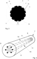
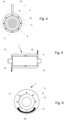
- the LED-UV emitters 11 can be arranged distributed over the circumference of the roller core 8 of the roller 7 and, for example, extend in a network-like manner over the peripheral surface, as in Fig 1 and 3 is indicated.
- the UV sources 10 designed as LED-UV emitters 11 can be inserted into groove-like depressions 16, which extend over the circumference of the roller core 8 over the width of the roller 7.
- the depressions 16 may have a reflective surface and a UV radiation focusing geometry, as shown in FIGS Figs. 2 and 3 shown.
- the channel-like depressions 16 can be filled with various media, for example liquids or gases, these media being as permeable as possible must be suitable for UV radiation and should have an advantageous optical density.
- the media can also serve as a heat transfer medium and dissipate unwanted process heat.
- the heat that arises during radiation emission can be transferred via the metallic ones via the back of the LED-UV emitters 11 Remove the roller core 8 or the media present in the recesses 16. It is also possible to equip the roller core 8 with cooling holes for water cooling, which is coupled to a cooling device in a manner familiar to those skilled in the art. By dissipating the heat from the LED-UV emitters 11, heating of the LED-UV emitters 11, which leads to functional restrictions, is avoided and a relatively large radiation output or a low wavelength of the UV radiation can also be achieved, with lower wavelengths due to higher energy contents Curing of the UV varnish 3 can be an advantage.
- the control of the UV sources 10, which are advantageously only supplied with voltage when they are aligned in the direction of the substrate 2, i.e. there is a relatively direct radiation path, is carried out by an electronic control with which the position is detectable, or an in Fig. 6 Arrangement of a live contact segment 20 shown is possible, which is acted upon by the contacts 21 assigned to the LED-UV emitters 11 or light segments 17 to close electrical circuits depending on the rotational position of the roller 7. A circuit is only closed to supply energy to the LED-UV emitters 11 when the light segments 17 with the associated contacts 21 are in the area of the arcuate contact segment 20. This makes it possible to switch the LED UV lamps 11 on and off sequentially, which results in a saving of electrical energy and a reduction in heat generation.
- the roller covering 9 of the roller 7, which is permeable to UV radiation, has a thickness of approximately 2% to 80%, preferably between 10% and 20% of the radius of the roller 7 and has an elasticity, for example with a hardness of between 30 and 60 Shore-A.
- the roller covering 9 can consist of various materials that are transparent to UV radiation, with a low extinction coefficient being advantageous in order to achieve a high radiation intensity.
- elastic polyurethane materials, silicone rubbers or other transparent elastic rubbers can be used, which preferably do not contain any fillers that increase the extinction coefficient.
- the LED-UV emitters 11 assigned to the roller core 8 can be enclosed directly by the roller covering 9. Then the beam path can without additional material transfer from the LED-UV lamp 11 directly into the roller covering 9. This structure can be easily implemented by fixing the LED-UV emitters 11 on the roll core 8 and casting the roll covering 9 around it.
- the roller covering 9, which consists of a silicone rubber mixture, can be applied to the roller core 8, for example in several layers, with a relatively elastic layer with very good adhesion to the roller core 8 being applied in a brushing process, then the roller 7 precoated in this way is transferred to a casting mold and the majority of the silicone rubber is cast with a grade that has advantageous mechanical properties in terms of elasticity and durability.
- it can be subjected to surface treatments or a release agent can be used in the production of the roller 7.
- roller covering 9 can also be designed in such a way that it is completely or partially replaceable. This means you can create different surface structures if necessary without having to have different rollers 7 available. In addition, worn roller coverings 9 can be replaced without having to produce a completely new roller 7.
- the roller covering 9 can be designed in such a way that after its removal, the individual LED-UV emitters 11 or light segments 17 can be reached in order to enable replacement if necessary.
- the roller covering 9 can, for example, be designed as a kind of shell that can be pushed over the roller core 8.
- An axial fixation of the roller covering 9 can preferably take place on the end faces of the roller 7 with appropriate holders.
- the roller covering 9 can be provided with protuberances or extensions or the like, which engage in corresponding recesses in the roller core 8.
- the roller covering 9 When the roller covering 9 is pulled onto the roller core 8, the roller covering 9 can be elastically stretched so that it also rests against the roller core 8 in a pre-stressed manner.
- roller covering 9 can be provided with a structure on its peripheral surface 14, which is produced by subsequent processing or by a casting process in which the structure of the die is incorporated into the casting mold.
- the highest possible radiation intensity when curing the UV varnish 3 is advantageous, since then work can be carried out with a high process speed and/or a low reactivity of the UV varnish 3.
- All types of electromagnetic radiation that are suitable for activating the photoinitiator or starting the radical reaction through another process can be used to cure the UV varnish 3. It is important to ensure that the radiation is not absorbed by the roller covering 9.
- the feed of Substart 2 is 5 or 10m/min. Good curing of the UV varnish 3 is achieved.
- the edge areas of the substrate 2 are of good optical quality. There is no evidence of roller unwinding and subsequent post-hardening is not absolutely necessary.
- the UV varnish 3 used includes a polyether acrylate as a reactive resin component, which enables a high-quality and lightfast varnish for indoor use.
- TMP03TA is used as the reactive diluent, which is favorable in terms of labeling.
- TPO-L is used as the photoinitiator, which works very well at the wavelength of the radiation used.
- Airex 901W was used as the defoamer and Tego Rad 2650 as the leveling agent.
Landscapes
- Engineering & Computer Science (AREA)
- Mechanical Engineering (AREA)
- General Engineering & Computer Science (AREA)
- Physics & Mathematics (AREA)
- Plasma & Fusion (AREA)
- Textile Engineering (AREA)
- Life Sciences & Earth Sciences (AREA)
- Microbiology (AREA)
- Coating Apparatus (AREA)
- Application Of Or Painting With Fluid Materials (AREA)
- Supply, Installation And Extraction Of Printed Sheets Or Plates (AREA)
- Printing Methods (AREA)
Priority Applications (8)
| Application Number | Priority Date | Filing Date | Title |
|---|---|---|---|
| EP22194476.2A EP4335555A1 (fr) | 2022-09-07 | 2022-09-07 | Procédé et dispositif pour durcir une peinture uv |
| JP2025513306A JP2025528505A (ja) | 2022-09-07 | 2023-08-31 | Uvワニスを硬化させるための方法及び装置 |
| KR1020257007305A KR20250088479A (ko) | 2022-09-07 | 2023-08-31 | Uv 바니시를 경화하기 위한 방법 및 장치 |
| CN202380064093.1A CN119894611A (zh) | 2022-09-07 | 2023-08-31 | 用于固化uv清漆的方法和设备 |
| PCT/EP2023/073963 WO2024052217A1 (fr) | 2022-09-07 | 2023-08-31 | Procédé et appareil de durcissement de vernis uv |
| AU2023337377A AU2023337377A1 (en) | 2022-09-07 | 2023-08-31 | Method and apparatus for curing uv varnish |
| US19/108,177 US20260077387A1 (en) | 2022-09-07 | 2023-08-31 | Method and Apparatus for Curing Varnish |
| MX2025002673A MX2025002673A (es) | 2022-09-07 | 2025-03-06 | Metodo y aparato para curar barniz ultravioleta (uv) |
Applications Claiming Priority (1)
| Application Number | Priority Date | Filing Date | Title |
|---|---|---|---|
| EP22194476.2A EP4335555A1 (fr) | 2022-09-07 | 2022-09-07 | Procédé et dispositif pour durcir une peinture uv |
Publications (1)
| Publication Number | Publication Date |
|---|---|
| EP4335555A1 true EP4335555A1 (fr) | 2024-03-13 |
Family
ID=83271556
Family Applications (1)
| Application Number | Title | Priority Date | Filing Date |
|---|---|---|---|
| EP22194476.2A Pending EP4335555A1 (fr) | 2022-09-07 | 2022-09-07 | Procédé et dispositif pour durcir une peinture uv |
Country Status (8)
| Country | Link |
|---|---|
| US (1) | US20260077387A1 (fr) |
| EP (1) | EP4335555A1 (fr) |
| JP (1) | JP2025528505A (fr) |
| KR (1) | KR20250088479A (fr) |
| CN (1) | CN119894611A (fr) |
| AU (1) | AU2023337377A1 (fr) |
| MX (1) | MX2025002673A (fr) |
| WO (1) | WO2024052217A1 (fr) |
Citations (5)
| Publication number | Priority date | Publication date | Assignee | Title |
|---|---|---|---|---|
| DE10144579C2 (de) | 2001-08-07 | 2003-12-04 | Reiner Goetzen | Verfahren und Vorrichtung zur Herstellung von Fein- bis Mikrostrukturen und/oder komplexen Mikrosystemen |
| EP1951436B1 (fr) | 2005-11-24 | 2009-08-12 | S.D. Warren Company, D/B/A | Dispositif de revetement comprenant une substance de revetement fluide destinee a des surfaces lisses ou structurees |
| EP1667836B1 (fr) | 2003-10-01 | 2013-07-17 | Fraunhofer-Gesellschaft zur Förderung der angewandten Forschung e.V. | Outil et procede de fabrication d'une surface microstructuree |
| DE102013215739A1 (de) * | 2013-08-09 | 2015-02-12 | Fraunhofer-Gesellschaft zur Förderung der angewandten Forschung e.V. | Vorrichtung zur Mikrostrukturierung von Oberflächen |
| GB2576922A (en) * | 2018-09-06 | 2020-03-11 | Stensborg As | An optical engine for an imprinter |
Family Cites Families (2)
| Publication number | Priority date | Publication date | Assignee | Title |
|---|---|---|---|---|
| DE102010029423A1 (de) * | 2009-07-07 | 2011-01-13 | Manroland Ag | Verfahren und Vorrichtung zur Erzeugung einer strukturierten Schicht |
| CN108267930B (zh) * | 2018-01-17 | 2020-08-18 | 南开大学 | 一种固化纳米压印装置 |
-
2022
- 2022-09-07 EP EP22194476.2A patent/EP4335555A1/fr active Pending
-
2023
- 2023-08-31 WO PCT/EP2023/073963 patent/WO2024052217A1/fr not_active Ceased
- 2023-08-31 KR KR1020257007305A patent/KR20250088479A/ko active Pending
- 2023-08-31 CN CN202380064093.1A patent/CN119894611A/zh active Pending
- 2023-08-31 US US19/108,177 patent/US20260077387A1/en active Pending
- 2023-08-31 JP JP2025513306A patent/JP2025528505A/ja active Pending
- 2023-08-31 AU AU2023337377A patent/AU2023337377A1/en active Pending
-
2025
- 2025-03-06 MX MX2025002673A patent/MX2025002673A/es unknown
Patent Citations (5)
| Publication number | Priority date | Publication date | Assignee | Title |
|---|---|---|---|---|
| DE10144579C2 (de) | 2001-08-07 | 2003-12-04 | Reiner Goetzen | Verfahren und Vorrichtung zur Herstellung von Fein- bis Mikrostrukturen und/oder komplexen Mikrosystemen |
| EP1667836B1 (fr) | 2003-10-01 | 2013-07-17 | Fraunhofer-Gesellschaft zur Förderung der angewandten Forschung e.V. | Outil et procede de fabrication d'une surface microstructuree |
| EP1951436B1 (fr) | 2005-11-24 | 2009-08-12 | S.D. Warren Company, D/B/A | Dispositif de revetement comprenant une substance de revetement fluide destinee a des surfaces lisses ou structurees |
| DE102013215739A1 (de) * | 2013-08-09 | 2015-02-12 | Fraunhofer-Gesellschaft zur Förderung der angewandten Forschung e.V. | Vorrichtung zur Mikrostrukturierung von Oberflächen |
| GB2576922A (en) * | 2018-09-06 | 2020-03-11 | Stensborg As | An optical engine for an imprinter |
Also Published As
| Publication number | Publication date |
|---|---|
| WO2024052217A1 (fr) | 2024-03-14 |
| KR20250088479A (ko) | 2025-06-17 |
| CN119894611A (zh) | 2025-04-25 |
| US20260077387A1 (en) | 2026-03-19 |
| AU2023337377A1 (en) | 2025-03-20 |
| MX2025002673A (es) | 2025-06-02 |
| JP2025528505A (ja) | 2025-08-28 |
Similar Documents
| Publication | Publication Date | Title |
|---|---|---|
| DE10346124B4 (de) | Werkzeug und Verfahren zum Erzeugen einer mikrostrukturierten Oberfläche und Verwendung eines Werkzeuges sowie damit erzeugter Gegenstand | |
| DE69611851T2 (de) | Haltevorrichtung für ein Substrat und Verfahren und Vorrichtung zum Polieren eines Substrates | |
| DE102012212751B4 (de) | Verfahren, vorrichtung und systeme zum verteilen von strahlenhärtbarer geltinte | |
| EP3370886A2 (fr) | Procédé pour générer des effets de surface, en particulier dans des couches durcissables par uv, dispositif pour réaliser ces effets et article ainsi obtenu | |
| DE60314097T2 (de) | Heissschmelzbeschichtungszusammensetzung für folienübertragung und giessprozess | |
| DE102015104321A1 (de) | Verfahren, Applikationsvorrichtung und Druckvorrichtung zum Applizieren einer Folie | |
| EP1238789B1 (fr) | Méthode de fabrication d'une cylindre de grainage en caoutchouc silicone pour l'estampage en continu de la surface d'une feuille thermoplastique | |
| DE102019124309A1 (de) | Vorrichtung und Verfahren zur Erzeugung mattierungsmodulierter Polymerschichten | |
| DE102016224592A1 (de) | Werkzeug und Verfahren zur Herstellung einer mikrostrukturierten Oberflächenbeschichtung | |
| MXPA04001038A (es) | Procedimiento para reparar superficies de sustrato recubiertas. | |
| EP1310381A2 (fr) | Matériaux en bande avec une surface structurée, leur procédé de fabrication ainsi que leur utilisation | |
| WO2024052217A1 (fr) | Procédé et appareil de durcissement de vernis uv | |
| EP3261843B1 (fr) | Dispositif pour l'application des éléments décoratifs sur récipients | |
| DE102021112873A1 (de) | Verfahren und Vorrichtung zum Direktdruck auf Behälter für Abfüllprodukte | |
| EP3159740A1 (fr) | Procede de fabrication generative de formes d'impression en relief | |
| EP1527902B1 (fr) | Méthode et dispositif pour la fabrication d'une bande de materiau | |
| DE102006057966B4 (de) | Auftrags-Bestrahlungs-System für die Elektronenstrahlhärtung | |
| WO2018103940A1 (fr) | Procédé pour imprimer des micro- et/ou nanostructures | |
| DE102007053543B4 (de) | Vorrichtung zur Bestrahlung von Elementen mit UV-Licht sowie Verfahren zu deren Betrieb | |
| DE19706619A1 (de) | Verfahren zur Beschichtung von Kunststoff-Platten und beschichtete Kunststoff-Platten | |
| EP1644456B1 (fr) | Dispositif et procede pour traiter une substance par rayonnement uv | |
| DE10224514A1 (de) | UV-Härtung von Lacken mit Inertisierung | |
| WO2024213628A1 (fr) | Dispositif, dispositif d'impression et procédé de durcissement d'encre d'impression, de laque ou d'adhésif | |
| DE102009051174B4 (de) | Verfahren und Vorrichtung für eine Veredelung eines Druckerzeugnisses mittels maschinellen Auftrags von Pulver | |
| DE102006004144A1 (de) | Vorrichtung und Verfahren zum Beschichten von Platten |
Legal Events
| Date | Code | Title | Description |
|---|---|---|---|
| PUAI | Public reference made under article 153(3) epc to a published international application that has entered the european phase |
Free format text: ORIGINAL CODE: 0009012 |
|
| STAA | Information on the status of an ep patent application or granted ep patent |
Free format text: STATUS: REQUEST FOR EXAMINATION WAS MADE |
|
| 17P | Request for examination filed |
Effective date: 20231128 |
|
| AK | Designated contracting states |
Kind code of ref document: A1 Designated state(s): AL AT BE BG CH CY CZ DE DK EE ES FI FR GB GR HR HU IE IS IT LI LT LU LV MC MK MT NL NO PL PT RO RS SE SI SK SM TR |