EP4335560A1 - Dispositif et procédé de nettoyage d'une pièce - Google Patents
Dispositif et procédé de nettoyage d'une pièce Download PDFInfo
- Publication number
- EP4335560A1 EP4335560A1 EP22194880.5A EP22194880A EP4335560A1 EP 4335560 A1 EP4335560 A1 EP 4335560A1 EP 22194880 A EP22194880 A EP 22194880A EP 4335560 A1 EP4335560 A1 EP 4335560A1
- Authority
- EP
- European Patent Office
- Prior art keywords
- workpiece
- cleaning
- cleaning chamber
- workpiece holder
- openings
- Prior art date
- Legal status (The legal status is an assumption and is not a legal conclusion. Google has not performed a legal analysis and makes no representation as to the accuracy of the status listed.)
- Granted
Links
Images


Classifications
-
- B—PERFORMING OPERATIONS; TRANSPORTING
- B08—CLEANING
- B08B—CLEANING IN GENERAL; PREVENTION OF FOULING IN GENERAL
- B08B5/00—Cleaning by methods involving the use of air flow or gas flow
- B08B5/04—Cleaning by suction, with or without auxiliary action
- B08B5/043—Cleaning travelling work
-
- B—PERFORMING OPERATIONS; TRANSPORTING
- B23—MACHINE TOOLS; METAL-WORKING NOT OTHERWISE PROVIDED FOR
- B23Q—DETAILS, COMPONENTS, OR ACCESSORIES FOR MACHINE TOOLS, e.g. ARRANGEMENTS FOR COPYING OR CONTROLLING; MACHINE TOOLS IN GENERAL CHARACTERISED BY THE CONSTRUCTION OF PARTICULAR DETAILS OR COMPONENTS; COMBINATIONS OR ASSOCIATIONS OF METAL-WORKING MACHINES, NOT DIRECTED TO A PARTICULAR RESULT
- B23Q11/00—Accessories fitted to machine tools for keeping tools or parts of the machine in good working condition or for cooling work; Safety devices specially combined with or arranged in, or specially adapted for use in connection with, machine tools
- B23Q11/0042—Devices for removing chips
- B23Q11/0075—Devices for removing chips for removing chips or coolant from the workpiece after machining
-
- B—PERFORMING OPERATIONS; TRANSPORTING
- B08—CLEANING
- B08B—CLEANING IN GENERAL; PREVENTION OF FOULING IN GENERAL
- B08B5/00—Cleaning by methods involving the use of air flow or gas flow
- B08B5/02—Cleaning by the force of jets, e.g. blowing-out cavities
- B08B5/023—Cleaning travelling work
Definitions
- the invention relates to a device and a method for cleaning a workpiece, with at least one cleaning chamber for receiving the workpiece arranged on a workpiece holder, further with at least one vacuum device for generating a cleaning air stream guided through openings in the cleaning chamber, and with a cleaning chamber and / or the movement unit acting on the workpiece holder and/or the workpiece to generate a relative movement of the workpiece relative to the openings.
- the prior art according to the EP 1 757 677 B1 a device and a method for removing oils, fats or similar hydrophobic components from surfaces of such a workpiece using a system are described.
- the system has a spraying device for applying a specified dry powder Porosity.
- the dry powder containing the adsorbed hydrophobic components is removed using a removal unit.
- the dry powder then has to be processed, which is sometimes complex and, in particular, energy-intensive.
- an alternative state of the art is based on: DE 20 2013 012 237 U1 so that the workpiece is cleaned with the help of an air stream flowing through the cleaning chamber.
- the air flow can then be cleaned again using a filter or separator to separate the impurities removed using the air flow.
- the air flow is guided in a closed air circuit using a vacuum source such as a suction fan.
- the cleaning chamber has a hollow cylindrical jacket with a vertically aligned longitudinal central axis, on which an air inlet is formed and the lower axial end either forms the air outlet or is provided with an end wall. This allows a large number of objects or workpieces to be cleaned in a relatively short time.
- a movement unit is provided which is connected to the workpiece holder and/or the cleaning chamber. During the cleaning process, the movement unit ensures a relative movement between the workpiece holder and an air inlet opening.
- a hood formed from two hood parts that are partially slidable into one another is provided. The two hood parts can be moved in opposite directions and relative to each other. For this purpose there is an actuation device with control electronics intended.
- the actuating device is controlled in such a way that the two hood parts are moved away from each other into the open position and are at least partially held in this position, so that the air inlet opening is designed in the shape of a slot between the two hood parts. In this way, optimal cleaning of workpieces should be made possible.
- the invention is based on the technical problem of further developing such a device for cleaning a workpiece in such a way that the device can easily be integrated into a production line with continuous feed and removal of the workpieces.
- an appropriately designed procedure should be made available.
- the invention proposes in a generic device that at least one linear drive is provided for the predominantly synchronous drive of the cleaning chamber and the workpiece holder and thus of the workpiece.
- a linear drive is first and foremost used.
- This can be used, for example, as a timing belt conveyor be trained.
- the cleaning chamber and the workpiece holder can be driven predominantly synchronously. This means that the cleaning chamber and the workpiece holder as well as the workpiece arranged on the workpiece holder are largely transported in the same direction and at the same speed.
- the linear drive mainly takes care of this.
- the movement unit additionally ensures that the workpiece performs a relative movement relative to the openings of the cleaning chamber.
- openings of the cleaning chamber are typically at least one air inlet opening and at least one air suction opening.
- the cleaning air flow passed through the openings of the cleaning chamber is generated using the at least one negative pressure device.
- the negative pressure device can be a suction pump, a blower, etc., which consequently generates a negative pressure at the one or more air suction openings, so that air flowing in via the one or more air inlet openings forms the desired cleaning air flow through the cleaning chamber.
- This cleaning air flow ensures that the workpiece holder that passes through with the workpiece arranged thereon and in particular the workpiece is cleaned with the help of the cleaning air flow.
- the air flow is guided through the cleaning chamber in such a way that a high flow speed of the cleaning air flow is observed, at least in the area of the workpiece to be cleaned.
- a filter connected upstream of the vacuum device ensures that the previously mentioned components are separated therein in the cleaning air flow.
- this applies to the chips or dust and, on the other hand, to any liquid that can be reused in a circuit even after it has been separated on the filter.
- an additional procedure can be carried out in such a way that the workpiece holder with the workpiece arranged thereon or thereon is made to vibrate at least when passing through the cleaning chamber using a vibration device.
- the cleaning air flow can be warmed up, preferably by waste heat from the vacuum device.
- the viscosity of, for example, oil or wax adhering to the workpiece can be changed, which as a result can be removed even better from the workpiece by the cleaning air stream.
- the invention ensures that any chips or dust adhering to the workpiece, as well as liquid, are loosened and entrained by the cleaning air stream flowing at high speed in this area and detached from the surface. This further intensifies the cleaning effect.
- the cleaning chamber is designed at least in two parts with a base provided in or on the workpiece holder and a cover that optionally closes the base.
- the additional procedure is usually such that the workpiece holder is mounted on a slide so that it can move.
- the carriage can then be acted upon along a carriage guide using the linear drive.
- the slide is moved using the linear drive through a magnetic field that advances in the linear direction of the slide guide.
- the linear drive moves the slide and thus the workpiece holder along the slide guide, for example via a spindle or a spindle drive.
- the spindle is rotated and the carriage is fixed, for example, to a spindle nut rotatably mounted on the spindle, which moves in the linear direction as a result of the rotations of the spindle.
- a toothed belt conveyor can also be used as a linear drive.
- the workpiece holder is typically mounted so that it can move relative to the slide. In this way, the workpiece holder together with the base can be placed against the ceiling as part of the cleaning chamber.
- the connection between the base and the ceiling is at least non-positive. Of course, a frictional or form-fitting connection is also conceivable at this point.
- the base as part of the cleaning chamber on the workpiece holder, is initially accessible from above or from the side if the ceiling is not present.
- This allows the workpiece to be placed in the base as part of the cleaning chamber. This can be done, for example, manually, using a robot or some other handling device to reach.
- the workpiece holder and consequently the base of the cleaning chamber is equipped with appropriate guides or holders for the workpiece in question.
- the workpiece is advantageously a rotationally symmetrical workpiece, it can be placed, for example, on a bearing mandrel that accommodates the workpiece. This means that the workpiece is stored properly on the workpiece holder in the base of the cleaning chamber. This promotes the additional relative movement of the workpiece relative to the openings of the cleaning chamber in connection with cleaning. All that is required is that the movement unit acts on the cleaning chamber, the workpiece holder and/or the workpiece as such.
- the workpiece holder can be equipped with differently designed workpieces as required, so that particularly efficient cleaning of the, in this case, several workpieces on the matching workpiece holder is achieved.
- the fact that the base, as a component of the cleaning chamber, typically represents a component of the workpiece holder or is designed as a recess embedded in the workpiece holder also contributes to this.
- the workpiece holder itself takes over the function of the base and for this purpose has one or more recesses that accommodate the respective workpiece.
- the recess is equipped with the bearing mandrel already mentioned and mentioned as an example, onto which the workpiece to be cleaned is placed. As I said, this can be done manually using a Robot or otherwise with a handling tool. Since the base of the cleaning chamber is therefore formed by the workpiece holder, all that is required to define the cleaning chamber is that the workpiece holder as a whole is positioned against the ceiling in question.
- the cleaning chamber is closed as a whole and the desired cleaning air flow can then be generated through the openings using vacuum cleaning, which is in the area of the workpiece to be cleaned is accelerated by targeted cross-sectional narrowing in order to effectively remove chips or dust adhering to the workpiece as well as any liquids. This is where the main advantages can be seen.
- the ceiling can be equipped with its own drive and is designed at least as part of a strand guided around transport rollers.
- at least one transport roller is equipped with the drive.
- the drive of the transport roller in question is selected so that the strand guided around the transport rollers, which is advantageously a conveyor belt guided around the transport rollers, moves at the same speed as the linear drive. In this way, the previously mentioned predominantly synchronous drive of the cleaning chamber and the workpiece holder and thus the workpiece occurs.
- the conveyor belt in question is typically a toothed belt conveyor belt, which generates a negative pressure in the cleaning chamber at associated openings.
- the conveyor belt preferably at least partially encloses the vacuum device.
- the opening in question in the conveyor belt defines at least one air extraction opening.
- the movement unit is typically a roller that acts on the workpiece and is generally forced to rotate.
- the roller can typically be clamped in a rotating manner between the workpiece and a guide.
- the stationary guidance is usually found in an area in which the conveyor belt is also implemented and provided.
- fixed guides are provided on both sides, which hold the workpiece holder that can be moved on the slide between them.
- the roller in question becomes clamped in rotation.
- the roller is therefore forced to rotate and at the same time ensures a rotation of the workpiece, which is generally mounted on the bearing mandrel, so that the desired relative movement of the workpiece relative to the openings for the cleaning air flow is observed.
- the workpiece cleaned in this way is - as mentioned - typically and preferably a rotationally symmetrical workpiece.
- workpieces that are not rotationally symmetrical can also be cleaned with the device described.
- a holder that holds the workpiece which in turn is generally mounted on the bearing mandrel and is rotated via the movement unit.
- a particularly effective dry cleaning takes place overall, which at the same time opens up the possibility of being able to reuse any liquid, oil, etc. that has been removed.
- the workpieces in question can particularly advantageously be, for example, components of an electric motor such as rotors, stators but also all other products that are advantageously required in automotive production, such as bearing bushes, joint shells, etc.
- the roller or clamping roller which is advantageously provided in connection with the movement unit, can be mounted in a resilient manner overall. It is also understood that the roller or clamping roller, if necessary, has at least one surface that produces a frictional connection, for example has a rubber or plastic coating or is itself made of rubber or plastic. In this way, a perfect transfer of rotations from the roller or clamping roller to the workpiece in question is ensured.
- the additionally provided vibration device intensifies the cleaning effect, but is viewed as an option overall and is therefore not absolutely necessary. Either way, a complete contour cleaning of the workpiece in question takes place because it completes at least one revolution during the cleaning process. Of course it is also within the scope of Invention that the workpiece completes more than one revolution when passing through the device.
- both the linear drive and the drive for the at least one transport roller of the conveyor belt can basically be coordinated with one another, but can be designed independently of the speed of the conveyor system in question.
- the subject of the invention is also a method for cleaning a workpiece, as described in detail in claim 15.
- a device for cleaning a workpiece 1 is shown in the figures.
- the workpiece 1 in question is as shown in the illustration Fig.1 and 2 around a rotationally symmetrical workpiece 1, for example a rotor or stator, as components of an electric motor to be subsequently manufactured.
- the workpiece 1 is cleaned using air, so it is designed as dry cleaning.
- the workpiece 1 in question is first arranged on a workpiece holder 2. Based on Fig. 5 By looking at the workpiece holder 2, one can see and understand that, in addition to the workpiece 1, another workpiece 1' can also be accommodated in, on or on the workpiece holder 2.
- the workpiece holder 2 is equipped for this purpose with at least one recess 3, which functions and is designed as a base 3 provided in or on the workpiece holder 2 of a cleaning chamber 3, 5 to be described in more detail below.
- the base 3 is for this purpose with one inside provided bearing mandrel 4, which is used to hold the workpiece 1.
- the workpiece 1, 1 'to be cleaned is inserted into the recess 3 from above, for example manually or with the help of a gripper, a robot or otherwise, and is placed onto the bearing mandrel 4. Now the workpiece 1, 1' is positioned in or on the workpiece holder 2 in order to undergo subsequent cleaning with the help of air.
- a ceiling 5 which optionally closes the base 3 is also provided as a further component of the cleaning chamber 3, 5.
- the base 3 is initially open in order to be able to place the workpiece 1, 1 'in particular, namely, according to the exemplary embodiment, on the bearing mandrel 4 inside the recess 3 or base 3 of the cleaning chamber 3, 5. If the workpiece holder 2 is transported together with the workpiece 1 along the device in the conveying direction F, the recess 3 is now closed with the aid of a cover 5, so that the cleaning chamber 3, 5 is then closed and the workpiece 1 is cleaned Can be carried out inside the closed cleaning chamber 3, 5.
- a movement unit 7 is provided, with the help of which a relative movement of the workpiece 1 relative to openings 8, 9 in the cleaning chamber 3, 5 is produced.
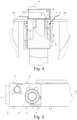
- the mentioned openings 8, 9 in the cleaning chamber 3, 5 are, on the one hand, about an air inlet opening 9 and on the other hand an air suction opening 8, which can best be seen from the sectional view in the Fig. 4 can understand. Outside air enters the cleaning chamber 3, 5 via the air inlet opening 9 and then leaves the cleaning chamber 3, 5 via the air suction opening 8, so that in this way the air in the Fig. 4 schematically drawn cleaning air flow 6 is defined.
- several openings 8, 9 can also be realized.
- a linear drive 10 is provided for the predominantly synchronous drive of the cleaning chamber 3, 5 and the workpiece holder 2 and thus the workpiece 1, 1 '.
- a vacuum device 11 for generating the cleaning air flow 6 through the previously mentioned openings 8, 9 in the cleaning chamber 3, 5, namely starting at the air inlet opening 9 and ending in the air suction opening 8, which is acted upon using the vacuum device 11.
- the design of the linear drive 10 can be done in different ways.
- the linear drive 10 generates an electromagnetic field that progresses in the conveying direction F and in this way moves individual carriages 12 that are movable in the conveying direction F in the conveying direction F.
- the workpiece holder 2 in question is movably mounted on a slide 12 and is moved together with the slide 12 by the linear drive 10 along the conveying direction F or along the slide guide.
- the respective carriage 12 is acted upon using the linear drive 10, which - as I said - can be done by an electromagnetic field progressing in the conveying direction F or simply mechanically using a spindle drive, as has already been described in detail in the introduction.
- a toothed belt conveyor is also conceivable.
- the workpiece holder 2 in question is mounted so that it can move relative to the carriage 12.
- the device is equipped with a lifting rail guide 13, which ensures that when the workpiece holder 2 is transported on the carriage 12 along the conveying direction F, the workpiece holder 2, in particular based on the Fig. 2 can carry out a comprehensible lifting movement relative to the carriage 12.
- Fig. 2 reproduced phases A to G differ from each other, which are explained in more detail below. Either way, the cleaning chamber 3, 5 is initially open with regard to its base 3 and is only then closed with the ceiling 5.
- the workpiece 1 or 1 'in question can be inserted into the recess 3 or the base 3.
- the workpiece holder 2 is then positioned against the ceiling 5. This results in an at least non-positive connection between the base 3 of the cleaning chamber 3, 5 and the ceiling 5.
- the ceiling 5 is equipped with its own drive. It can be seen that the ceiling 5 is designed at least as part of a strand guided around indicated transport rollers 14. At least one of the transport rollers 14 is equipped with its own drive.
- the strand is a conveyor belt 5 guided around the transport rollers 14.
- the conveyor belt 5 is designed as a toothed belt conveyor belt.
- the conveyor belt 5 defines the ceiling 5 of the cleaning chamber 3, 5, against which the base 3 is placed using the lifting rail guide 13.
- the conveyor belt 5 can completely or partially enclose the vacuum device 11, as can be seen from the Fig. 2 can understand.
- the design is such that the vacuum device 11 on associated openings 8 of the conveyor belt 5, namely the air suction openings 8, generate the desired negative pressure in the cleaning chamber 3, 5.
- the previously mentioned cleaning air flow 6 is defined overall.
- the movement unit 7 is a roller 7 which acts on the workpiece 1 or 1 '.
- the roller 7 is forced to rotate.
- the roller 7 can be clamped in a rotating manner between the workpiece 1 or 1 'and additionally a guide 15.
- the design is such that when the carriage 12 in question and the workpiece holder 2 carried with it are transported along the conveying direction F, the roller 7 in question comes into contact with the respective lateral stationary guide 15 and is thereby set in rotation. These rotations of the roller 7 are then transmitted to the workpiece 1, 1 ', which as a result rotates relative to the stationary bearing mandrel 4, namely within the recess or base 3 as part of the cleaning chamber 3, 5.
- the recess 3 together with the bearing mandrel 4 and the workpiece 1 accommodated therein, defines a slot guide on both sides for the cleaning air flow 6, which ensures that the air entering via the air inlet opening 9 up to the air suction opening 8 in this way has a cross-sectional narrowing in the Area of the relevant workpiece 1 or 1 'passes.
- the Venturi effect there is a significant increase in the flow speed of the cleaning air stream 6 and dust, chips and also liquid adhering to the surface of the workpiece 1 or 1 'are carried away by the cleaning air stream 6.
- a filter, not shown, located upstream of the vacuum device 11 now ensures that the dust or chips in question are separated together with the liquid carried and can be recycled if necessary, as already described in the introduction.
- the cleaning air stream 6 can also be warmed up in order to change the viscosity of adhering oils, waxes, rinsing liquids, etc. so that they can be better removed from the workpiece 1 or 1 'in question.
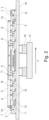
- the device in question is additionally equipped with a vibration device 16, 17, 18.
- the vibration device 16, 17, 18 is based on the exemplary embodiment as shown in FIG Fig. 3 composed of a vibration exciter 16, a counterweight 17 and a vibration clamp 18, which contains the vibrations generated by the vibration exciter 16 in the in Fig. 3 Transverse direction indicated by a double arrow compared to the conveying direction F is transferred to the guides 15 and thus to the individual workpiece holders 2 and consequently to the workpieces 1, 1 'to be cleaned.
- This further intensifies the cleaning effect inside the cleaning chamber 3, 5, because any chips or dust adhering to the additional adhesion forces of liquids are additionally released from the workpiece 1 or 1 'in question by the vibrations introduced by the vibration exciter 16.
- the functionality of the device is explained below using the individual step sequences A to G as shown in the Fig. 2 explained in more detail. It can be seen that to the left of the first step A, the workpiece 1, 1 'in question is placed inside the recess 3 and placed on the stationary bearing mandrel 4. At the same time, the carriage 12 with the workpiece holder 2 mounted thereon is moved in the conveying direction F by the linear drive 10.
- the workpiece holder 2 is raised relative to the carriage 12 using the lifting rail guide 13 and the result is that the base 3 of the cleaning chamber 3, 5 is placed against the ceiling 5 which optionally closes the base 3, namely against the one around the transport rollers 14 rotating conveyor belt or conveyor belt 5.
- the workpiece holder 2 is decoupled from the carriage 12 and in area C the two side guides 15 then ensure that the rollers 7 and thus also the workpiece 1 or 1 'in question rotate.
- the vacuum device 11 enters, the cleaning effect begins inside the cleaning chamber 3, 5 and the cleaning air flow 6 is formed through the openings 8, 9.
- the workpiece holder 2 in question is lowered again towards the carriage 12 using the lifting rail guide 13 and then moves out of the device in area G. While the workpiece holder 2 is in contact with the rotating conveyor belt 5, the workpiece holders 2 are moved in the conveying direction F using the conveyor belt 5 or additionally by the linear drive 10 via the associated carriage 12. In principle, the linear drive 10 can also continuously drive the workpiece holder 2 via the intermediate slides 12. This is irrelevant to the basic and described functionality.
Landscapes
- Engineering & Computer Science (AREA)
- Mechanical Engineering (AREA)
- Cleaning In General (AREA)
Priority Applications (1)
| Application Number | Priority Date | Filing Date | Title |
|---|---|---|---|
| EP22194880.5A EP4335560B1 (fr) | 2022-09-09 | 2022-09-09 | Dispositif et procédé de nettoyage d'une pièce |
Applications Claiming Priority (1)
| Application Number | Priority Date | Filing Date | Title |
|---|---|---|---|
| EP22194880.5A EP4335560B1 (fr) | 2022-09-09 | 2022-09-09 | Dispositif et procédé de nettoyage d'une pièce |
Publications (4)
| Publication Number | Publication Date |
|---|---|
| EP4335560A1 true EP4335560A1 (fr) | 2024-03-13 |
| EP4335560A8 EP4335560A8 (fr) | 2024-04-17 |
| EP4335560C0 EP4335560C0 (fr) | 2025-11-19 |
| EP4335560B1 EP4335560B1 (fr) | 2025-11-19 |
Family
ID=83270823
Family Applications (1)
| Application Number | Title | Priority Date | Filing Date |
|---|---|---|---|
| EP22194880.5A Active EP4335560B1 (fr) | 2022-09-09 | 2022-09-09 | Dispositif et procédé de nettoyage d'une pièce |
Country Status (1)
| Country | Link |
|---|---|
| EP (1) | EP4335560B1 (fr) |
Cited By (3)
| Publication number | Priority date | Publication date | Assignee | Title |
|---|---|---|---|---|
| DE202024105112U1 (de) | 2024-09-06 | 2024-10-24 | Neuhäuser GmbH | Vorrichtung zum Reinigen zumindest eines Förderbandes und/oder von mittels des Förderbandes transportierten Werkstücken |
| DE202024107080U1 (de) | 2024-12-06 | 2025-01-20 | Neuhäuser GmbH | Vorrichtung zum Reinigen zumindest eines Förderbandes und/oder von mittels des Förderbandes transportierten Werkstücken |
| DE202025100497U1 (de) | 2025-01-31 | 2025-02-12 | Neuhäuser GmbH | Vorrichtung zum Reinigen zumindest eines Förderbandes mit elektromagnetischer Strahlungsquelle |
Citations (7)
| Publication number | Priority date | Publication date | Assignee | Title |
|---|---|---|---|---|
| EP1757677B1 (fr) | 2005-08-22 | 2011-11-09 | Eurotec Vertriebsgesellschaft m.b.H. | Procédé et dispositif pour enlever des huiles, graisses ou constituants hydrophobes des surfaces d'un substrat |
| US20140020714A1 (en) * | 2012-07-19 | 2014-01-23 | Samsung Electro-Mechanics Co., Ltd. | Non-contact multi-transfer apparatus and method for removing dust by using the same |
| DE202013012237U1 (de) | 2013-03-01 | 2015-10-07 | Klaus Döhrer | Vorrichtung zum Reinigen eines Werkstücks |
| KR20190125809A (ko) * | 2018-04-30 | 2019-11-07 | 주식회사 새암 | 이물질 흡입수단을 구비한 러그캡 제조장치 |
| CN111921982A (zh) * | 2020-08-05 | 2020-11-13 | 石阡县穗香粮油购销有限公司 | 纯净大米的除杂工艺 |
| DE202020107100U1 (de) | 2020-12-09 | 2021-01-13 | Klaus Döhrer | Vorrichtung zum Reinigen eines Objekts |
| DE102020103090B3 (de) | 2020-02-06 | 2021-03-25 | Klaus Döhrer | Vorrichtung zum Reinigen eines Werkstücks |
-
2022
- 2022-09-09 EP EP22194880.5A patent/EP4335560B1/fr active Active
Patent Citations (7)
| Publication number | Priority date | Publication date | Assignee | Title |
|---|---|---|---|---|
| EP1757677B1 (fr) | 2005-08-22 | 2011-11-09 | Eurotec Vertriebsgesellschaft m.b.H. | Procédé et dispositif pour enlever des huiles, graisses ou constituants hydrophobes des surfaces d'un substrat |
| US20140020714A1 (en) * | 2012-07-19 | 2014-01-23 | Samsung Electro-Mechanics Co., Ltd. | Non-contact multi-transfer apparatus and method for removing dust by using the same |
| DE202013012237U1 (de) | 2013-03-01 | 2015-10-07 | Klaus Döhrer | Vorrichtung zum Reinigen eines Werkstücks |
| KR20190125809A (ko) * | 2018-04-30 | 2019-11-07 | 주식회사 새암 | 이물질 흡입수단을 구비한 러그캡 제조장치 |
| DE102020103090B3 (de) | 2020-02-06 | 2021-03-25 | Klaus Döhrer | Vorrichtung zum Reinigen eines Werkstücks |
| CN111921982A (zh) * | 2020-08-05 | 2020-11-13 | 石阡县穗香粮油购销有限公司 | 纯净大米的除杂工艺 |
| DE202020107100U1 (de) | 2020-12-09 | 2021-01-13 | Klaus Döhrer | Vorrichtung zum Reinigen eines Objekts |
Cited By (4)
| Publication number | Priority date | Publication date | Assignee | Title |
|---|---|---|---|---|
| DE202024105112U1 (de) | 2024-09-06 | 2024-10-24 | Neuhäuser GmbH | Vorrichtung zum Reinigen zumindest eines Förderbandes und/oder von mittels des Förderbandes transportierten Werkstücken |
| EP4706838A1 (fr) | 2024-09-06 | 2026-03-11 | Neuhäuser GmbH | Dispositif de nettoyage d'au moins une bande transporteuse et/ou de pièces transportées au moyen de la bande transporteuse |
| DE202024107080U1 (de) | 2024-12-06 | 2025-01-20 | Neuhäuser GmbH | Vorrichtung zum Reinigen zumindest eines Förderbandes und/oder von mittels des Förderbandes transportierten Werkstücken |
| DE202025100497U1 (de) | 2025-01-31 | 2025-02-12 | Neuhäuser GmbH | Vorrichtung zum Reinigen zumindest eines Förderbandes mit elektromagnetischer Strahlungsquelle |
Also Published As
| Publication number | Publication date |
|---|---|
| EP4335560C0 (fr) | 2025-11-19 |
| EP4335560B1 (fr) | 2025-11-19 |
| EP4335560A8 (fr) | 2024-04-17 |
Similar Documents
| Publication | Publication Date | Title |
|---|---|---|
| EP4335560B1 (fr) | Dispositif et procédé de nettoyage d'une pièce | |
| DE102005043602B4 (de) | Zahnradbearbeitungsmaschine sowie Verfahren zum Betrieb einer solchen Zahnradbearbeitungsmaschine | |
| EP1500451B1 (fr) | Méthode et dispositif pour chanfreiner des tubes | |
| EP2279819B1 (fr) | Dispositif d'usinage mécanique de pièces tubulaires ou en forme de tiges | |
| CH709642B1 (de) | Schleuderstation mit mindestens einer Druckluftreinigungsanordnung zum Entfernen einer Bearbeitungsflüssigkeit von einem Werkstück. | |
| EP0705655B1 (fr) | Machine comportant des dispositifs de rotation pouvant coulisser relativement l'un par rapport à l'autre | |
| EP1747841B1 (fr) | Dispositif pour la fabrication de pièces métalliques, notamment de profilés cylindriques à vis, par usinage par rotation et laminage d'ébauches cylindriques | |
| DE60012578T2 (de) | Werkzeugmaschine und verfahren zur bearbeitung von länglichen elementen, insbesondere metallischen profilelementen | |
| DE102014014417B4 (de) | Reinigungsvorrichtung und Schleuderstation | |
| DE202008001563U1 (de) | Verfahrbare Spanneinrichtung für Werkstücke | |
| EP1043087B1 (fr) | Machine de rectification et de durcissement pour arbres | |
| DE2446776C2 (de) | Verfahren zur Herstellung einer geteilten Futtermutter für ein Bohrfutter | |
| WO2008131988A1 (fr) | Mandrin de serrage pour le centrage de barres | |
| WO2009033929A2 (fr) | Tour | |
| DE10039883C1 (de) | Verfahren und Anordnung zur Handhabung, insbesondere zur Entnahme und/oder zum Einlegen eines Werkstückes wie Form- oder Frästeils aus oder in eine Produktionsmaschine wie Gieß- oder Fräsmaschine | |
| DE4416771A1 (de) | Verfahren und Vorrichtung zum spanenden Bearbeiten von Stangen, Rohren oder Rohrluppen | |
| DE102012104431A1 (de) | Bearbeitungsvorrichtung und Verfahren hierzu | |
| EP1509342A1 (fr) | Dispositif de nettoyage a sec de pieces | |
| EP1882568B1 (fr) | Dispositif et procédé destinés au déplacement de cadres de fenêtres | |
| DE29912657U1 (de) | Vorrichtung zum Schneiden von Rohren | |
| DE2001544C3 (de) | Vorrichtung zum Entfernen der an in einer automatischen, spanabhebenden Bearbeitungsstation bearbeiteten Werkstücken, insbesondere Getrieberädern, haftenden Kühl- und/oder Schneidflüssigkeit durch Zentrifugieren | |
| EP2206569A1 (fr) | Machine-outil et procédé de fabrication de plusieurs pièces usinées à partir d'une ébauche | |
| EP3614880B1 (fr) | Dispositif d'usinage de brosses à fixation par vissage | |
| DE888636C (de) | Vorrichtung zum gleichzeitigen Abdrehen stabfoermiger Werkstuecke, z. B. Automobilachsen, an beiden Enden | |
| DE69005667T2 (de) | Vorrichtung zum axialen Ein- und Ausspannen von Holzstämmen in Furnierscheidmaschinen. |
Legal Events
| Date | Code | Title | Description |
|---|---|---|---|
| PUAI | Public reference made under article 153(3) epc to a published international application that has entered the european phase |
Free format text: ORIGINAL CODE: 0009012 |
|
| STAA | Information on the status of an ep patent application or granted ep patent |
Free format text: STATUS: THE APPLICATION HAS BEEN PUBLISHED |
|
| AK | Designated contracting states |
Kind code of ref document: A1 Designated state(s): AL AT BE BG CH CY CZ DE DK EE ES FI FR GB GR HR HU IE IS IT LI LT LU LV MC MK MT NL NO PL PT RO RS SE SI SK SM TR |
|
| RIN1 | Information on inventor provided before grant (corrected) |
Inventor name: NEUHAEUSER, JUERGEN Inventor name: HENNING, MICHAEL |
|
| STAA | Information on the status of an ep patent application or granted ep patent |
Free format text: STATUS: REQUEST FOR EXAMINATION WAS MADE |
|
| 17P | Request for examination filed |
Effective date: 20240405 |
|
| RBV | Designated contracting states (corrected) |
Designated state(s): AL AT BE BG CH CY CZ DE DK EE ES FI FR GB GR HR HU IE IS IT LI LT LU LV MC MK MT NL NO PL PT RO RS SE SI SK SM TR |
|
| GRAP | Despatch of communication of intention to grant a patent |
Free format text: ORIGINAL CODE: EPIDOSNIGR1 |
|
| STAA | Information on the status of an ep patent application or granted ep patent |
Free format text: STATUS: GRANT OF PATENT IS INTENDED |
|
| GRAS | Grant fee paid |
Free format text: ORIGINAL CODE: EPIDOSNIGR3 |
|
| RIC1 | Information provided on ipc code assigned before grant |
Ipc: B08B 5/04 20060101AFI20250820BHEP Ipc: B23Q 11/00 20060101ALI20250820BHEP Ipc: B08B 5/02 20060101ALN20250820BHEP |
|
| INTG | Intention to grant announced |
Effective date: 20250902 |
|
| GRAA | (expected) grant |
Free format text: ORIGINAL CODE: 0009210 |
|
| STAA | Information on the status of an ep patent application or granted ep patent |
Free format text: STATUS: THE PATENT HAS BEEN GRANTED |
|
| AK | Designated contracting states |
Kind code of ref document: B1 Designated state(s): AL AT BE BG CH CY CZ DE DK EE ES FI FR GB GR HR HU IE IS IT LI LT LU LV MC MK MT NL NO PL PT RO RS SE SI SK SM TR |
|
| REG | Reference to a national code |
Ref country code: CH Ref legal event code: F10 Free format text: ST27 STATUS EVENT CODE: U-0-0-F10-F00 (AS PROVIDED BY THE NATIONAL OFFICE) Effective date: 20251119 Ref country code: GB Ref legal event code: FG4D Free format text: NOT ENGLISH |
|
| REG | Reference to a national code |
Ref country code: IE Ref legal event code: FG4D Free format text: LANGUAGE OF EP DOCUMENT: GERMAN |
|
| U01 | Request for unitary effect filed |
Effective date: 20251121 |
|
| U07 | Unitary effect registered |
Designated state(s): AT BE BG DE DK EE FI FR IT LT LU LV MT NL PT RO SE SI Effective date: 20251127 |
|
| PG25 | Lapsed in a contracting state [announced via postgrant information from national office to epo] |
Ref country code: ES Free format text: LAPSE BECAUSE OF FAILURE TO SUBMIT A TRANSLATION OF THE DESCRIPTION OR TO PAY THE FEE WITHIN THE PRESCRIBED TIME-LIMIT Effective date: 20251119 |
|
| PG25 | Lapsed in a contracting state [announced via postgrant information from national office to epo] |
Ref country code: NO Free format text: LAPSE BECAUSE OF FAILURE TO SUBMIT A TRANSLATION OF THE DESCRIPTION OR TO PAY THE FEE WITHIN THE PRESCRIBED TIME-LIMIT Effective date: 20260219 |
|
| PG25 | Lapsed in a contracting state [announced via postgrant information from national office to epo] |
Ref country code: HR Free format text: LAPSE BECAUSE OF FAILURE TO SUBMIT A TRANSLATION OF THE DESCRIPTION OR TO PAY THE FEE WITHIN THE PRESCRIBED TIME-LIMIT Effective date: 20251119 |
|
| PG25 | Lapsed in a contracting state [announced via postgrant information from national office to epo] |
Ref country code: RS Free format text: LAPSE BECAUSE OF FAILURE TO SUBMIT A TRANSLATION OF THE DESCRIPTION OR TO PAY THE FEE WITHIN THE PRESCRIBED TIME-LIMIT Effective date: 20260219 |
|
| PG25 | Lapsed in a contracting state [announced via postgrant information from national office to epo] |
Ref country code: IS Free format text: LAPSE BECAUSE OF FAILURE TO SUBMIT A TRANSLATION OF THE DESCRIPTION OR TO PAY THE FEE WITHIN THE PRESCRIBED TIME-LIMIT Effective date: 20260319 |
|
| PG25 | Lapsed in a contracting state [announced via postgrant information from national office to epo] |
Ref country code: PL Free format text: LAPSE BECAUSE OF FAILURE TO SUBMIT A TRANSLATION OF THE DESCRIPTION OR TO PAY THE FEE WITHIN THE PRESCRIBED TIME-LIMIT Effective date: 20251119 |