EP4335585A1 - Dispositif d'évacuation de copeaux pour machine-outil et système de fabrication - Google Patents
Dispositif d'évacuation de copeaux pour machine-outil et système de fabrication Download PDFInfo
- Publication number
- EP4335585A1 EP4335585A1 EP23196126.9A EP23196126A EP4335585A1 EP 4335585 A1 EP4335585 A1 EP 4335585A1 EP 23196126 A EP23196126 A EP 23196126A EP 4335585 A1 EP4335585 A1 EP 4335585A1
- Authority
- EP
- European Patent Office
- Prior art keywords
- chip
- cart
- machine tool
- connecting piece
- basket
- Prior art date
- Legal status (The legal status is an assumption and is not a legal conclusion. Google has not performed a legal analysis and makes no representation as to the accuracy of the status listed.)
- Pending
Links
Images




Classifications
-
- B—PERFORMING OPERATIONS; TRANSPORTING
- B23—MACHINE TOOLS; METAL-WORKING NOT OTHERWISE PROVIDED FOR
- B23Q—DETAILS, COMPONENTS, OR ACCESSORIES FOR MACHINE TOOLS, e.g. ARRANGEMENTS FOR COPYING OR CONTROLLING; MACHINE TOOLS IN GENERAL CHARACTERISED BY THE CONSTRUCTION OF PARTICULAR DETAILS OR COMPONENTS; COMBINATIONS OR ASSOCIATIONS OF METAL-WORKING MACHINES, NOT DIRECTED TO A PARTICULAR RESULT
- B23Q11/00—Accessories fitted to machine tools for keeping tools or parts of the machine in good working condition or for cooling work; Safety devices specially combined with or arranged in, or specially adapted for use in connection with, machine tools
- B23Q11/0042—Devices for removing chips
- B23Q11/0067—Devices for removing chips chip containers located under a machine or under a chip conveyor
-
- B—PERFORMING OPERATIONS; TRANSPORTING
- B23—MACHINE TOOLS; METAL-WORKING NOT OTHERWISE PROVIDED FOR
- B23Q—DETAILS, COMPONENTS, OR ACCESSORIES FOR MACHINE TOOLS, e.g. ARRANGEMENTS FOR COPYING OR CONTROLLING; MACHINE TOOLS IN GENERAL CHARACTERISED BY THE CONSTRUCTION OF PARTICULAR DETAILS OR COMPONENTS; COMBINATIONS OR ASSOCIATIONS OF METAL-WORKING MACHINES, NOT DIRECTED TO A PARTICULAR RESULT
- B23Q1/00—Members which are comprised in the general build-up of a form of machine, particularly relatively large fixed members
- B23Q1/25—Movable or adjustable work or tool supports
- B23Q1/44—Movable or adjustable work or tool supports using particular mechanisms
- B23Q1/48—Movable or adjustable work or tool supports using particular mechanisms with sliding pairs and rotating pairs
- B23Q1/4876—Movable or adjustable work or tool supports using particular mechanisms with sliding pairs and rotating pairs a single sliding pair followed parallelly by a single rotating pair
- B23Q1/488—Movable or adjustable work or tool supports using particular mechanisms with sliding pairs and rotating pairs a single sliding pair followed parallelly by a single rotating pair followed perpendicularly by a single rotating pair
-
- B—PERFORMING OPERATIONS; TRANSPORTING
- B23—MACHINE TOOLS; METAL-WORKING NOT OTHERWISE PROVIDED FOR
- B23Q—DETAILS, COMPONENTS, OR ACCESSORIES FOR MACHINE TOOLS, e.g. ARRANGEMENTS FOR COPYING OR CONTROLLING; MACHINE TOOLS IN GENERAL CHARACTERISED BY THE CONSTRUCTION OF PARTICULAR DETAILS OR COMPONENTS; COMBINATIONS OR ASSOCIATIONS OF METAL-WORKING MACHINES, NOT DIRECTED TO A PARTICULAR RESULT
- B23Q11/00—Accessories fitted to machine tools for keeping tools or parts of the machine in good working condition or for cooling work; Safety devices specially combined with or arranged in, or specially adapted for use in connection with, machine tools
-
- B—PERFORMING OPERATIONS; TRANSPORTING
- B23—MACHINE TOOLS; METAL-WORKING NOT OTHERWISE PROVIDED FOR
- B23Q—DETAILS, COMPONENTS, OR ACCESSORIES FOR MACHINE TOOLS, e.g. ARRANGEMENTS FOR COPYING OR CONTROLLING; MACHINE TOOLS IN GENERAL CHARACTERISED BY THE CONSTRUCTION OF PARTICULAR DETAILS OR COMPONENTS; COMBINATIONS OR ASSOCIATIONS OF METAL-WORKING MACHINES, NOT DIRECTED TO A PARTICULAR RESULT
- B23Q11/00—Accessories fitted to machine tools for keeping tools or parts of the machine in good working condition or for cooling work; Safety devices specially combined with or arranged in, or specially adapted for use in connection with, machine tools
- B23Q11/0042—Devices for removing chips
- B23Q11/0053—Devices for removing chips using the gravity force
Definitions
- the present disclosure relates to a device for chip removal for a machine tool and to a manufacturing system with a machine tool and a device for chip removal. According to various aspects, the present disclosure relates to compactly designed machine tools and their integration into manufacturing systems and systems for machining. Compactly designed machine tools are, for example, those with a work area that is smaller than 250 mm x 250 mm x 250 mm.
- the working space of the machine tool is smaller than 200 mm x 200 mm x 200 mm. In exemplary embodiments, the working space of the machine tool is smaller than 150 mm x 150 mm x 150 mm. In exemplary embodiments, the working space of the machine tool is smaller than 100 mm x 100 mm x 100 mm. In exemplary embodiments, the working space of the machine tool is smaller than 75mm x 75mm x 75mm.
- This information particularly concerns the possible feeds (travel paths) along the X, Y and Z axes.
- the workspace can be designed in a cube shape. However, cuboid-shaped installation spaces are also conceivable whose travel paths in X, Y and Z are not uniform. For example, machine tools designed in this way are suitable for precision mechanical processing, for example in the context of the production of watches, jewelry and the like. It goes without saying that other applications are also conceivable, for example in the field of medical technology, precision technology and the like.
- Machine tools and systems for metal-cutting production are known. From the US 2019/0084102 A1 a manufacturing system is known which has a plurality of compactly designed machine tools arranged one above the other and next to one another, which are arranged in a common housing, with an additional robot being provided for changing tools and/or workpieces. A system for collecting chips is also arranged in the housing.
- a vertical machining center which has a work area in which a vertically oriented tool spindle is arranged, the work area having a funnel-shaped taper towards the bottom with a bottom opening through which chips and the like can fall out of the work area.
- a (driven) chip conveyor is arranged below the bottom opening, which conveys chips falling out of the work area horizontally and vertically to an area behind the machining center, whereby the chips are transferred from above to a mobile chip cart.
- the present disclosure is based on the object of specifying a device for chip removal for a machine tool, which is particularly suitable for compact machine tools.
- the device should, if possible, take particular conditions into account in compactly designed machine tools. Help The device should allow manufacturing systems to be implemented that enable partially automated or even highly automated production even with only a small installation space. This refers, for example, to the collection and handling of chips.
- the device should, if possible, provide sufficient capacity for holding chips, so that at least temporarily self-sufficient or autonomous operation of the machine tool is possible.
- the device is intended to provide a container for holding chips, with quick change possible if the container is full.
- a manufacturing system is to be specified which has a machine tool and a device for chip removal. Overall, the manufacturing system should be designed to be compact and user-friendly.
- chips can be transferred as directly as possible, ideally without an additional (driven) chip conveyor between the work area and the chip cart.
- this allows for a compact design, also taking into account the automation technology and ancillary functions of the machine tool.
- connection between the working area of the machine tool and the chip carriage is sufficiently tight so that the tendency to get dirty when the machine tool is operated in the operating position of the connecting piece is low.
- the chip cart can simply be moved out of its parking space.
- a chip cart with a filled chip basket can be replaced by a new one with an empty chip basket.
- the connecting piece remains at the parking space when the chip cart has moved out of the parking space.
- the connecting piece is permanently coupled to the machine tool.
- the connecting piece is coupled sufficiently tightly to the chip cart.
- This includes, for example, a chip-tight coupling and in particular also a sufficiently coolant-tight coupling of the connecting piece to the chip carriage. In this way, contamination of the machine tool and its immediate surroundings with chips and coolants (cooling lubricants) is effectively reduced or avoided.
- the chip cart can be enclosed by the housing when the machine tool is operated to process workpieces. This creates an integral design.
- the enclosure has a door through which the chip cart can enter the parking space when the connecting piece is in the release position. Accordingly, the chip cart has a chassis.
- the chip cart is rollable/mobile.
- the chip carriage is changed from the front.
- the chip cart can be moved into or out of the parking space on the front of the machine tool. This is a departure from machine principles with chip conveyors and chip carts, where chips are transported to the rear or to the side. This simplifies the operation of the machine tool because essential components can be operated from one and the same side (front side, operator side).
- the device is used to handle chips (also referred to as: chip management). This includes collecting chips and at least partially collecting coolant fluid that adheres to the chips. Both chips and coolant fluid can be at least partially reused or recycled.
- the chips are transferred from the work area to the chip cart without an additional chip conveyor.
- chips can fall from the work area into the chip basket of the chip cart with the help of gravity.
- the chip cart has a column-shaped structure, with the connecting piece sitting above the chip cart and below the work space. This applies at least when there is a chip cart in the parking space.
- the chip cart can be placed below the working space of the machine tool. This makes chip transfer easier; chips can fall out of the work area and reach the chip cart without an additional drive.
- the column-like structure has a height (in the Z direction) that is at least twice the width (in the X direction) and/or twice the depth (in the Y direction) of the structure.
- a compact design of the machine tool allows the work area to be arranged at a certain height above the ground, for example at table height or standing height from an operator's perspective. In this way, the space under the work area can be used for other functions, such as chip management.
- the work area of the machine tool is located in the superstructure of a manufacturing system with a cabinet-like housing.
- the parking space for the chip cart is located in a substructure of a production system with a cabinet-like housing.
- the parking space for the chip cart is located - viewed from above - within the cross section occupied by the work space.
- a free, gravity-assisted chip transfer is made possible in the direction of the chip basket along a chip removal path.
- this includes a direct, free connection (without deflection) between the work area and the chip basket of the chip cart.
- the chip transfer between the chip removal opening and the chip basket takes place without a drive, with the chip removal path in particular extending essentially vertically between the working space and the chip basket. Chips can fall freely into the chip basket. A powered chip conveyor is not required.
- the connecting piece can be moved vertically, with a locking element being provided which secures the connecting piece in the release position if necessary. This means that the connecting piece can be specifically moved into the release position when a chip cart or a chip basket needs to be changed and/or emptied.
- the connecting piece rests in the operating position with a seal, in particular a circumferential seal, on an edge, in particular a circumferential edge, of the chip cart, the connecting piece having an opening in the direction of the chip basket, which in the operating position protrudes into the opening of the chip basket at the top.
- the connecting piece and the seal can rest sufficiently close to the edge of the chip cart. Nevertheless, it is possible to easily decouple the connecting piece from the chip cart.
- the chip cart has a chassis, a coolant handling section and the receptacle for the chip basket along its vertical extent, the coolant handling section being arranged between the chassis and the receptacle, the receptacle tightly enclosing the chip basket on several sides, and wherein the coolant handling section has an operating opening that is accessible to an operator even when the chip cart is arranged on the chip cart parking space. This may include opening a door of the enclosure.
- Moving the chip cart out of the parking space includes, for example, opening a door of the enclosure, moving the connecting piece into the release position and disconnecting a coolant discharge line in the coolant handling section.
- a coolant discharge line with a quick coupling is arranged in the coolant handling section, which can be operated through the operating opening. In this way, coolant fluid that was previously added to the chips can be collected.
- At least the receptacle of the chip cart is arranged above a movable KSS trough, the KSS trough having at least one recess for the chip cart, in particular for a chassis of the chip cart.
- the chip basket of the chip cart in the operational state, is arranged between the work area (or the connecting piece) and the coolant tank.
- the coolant tray is below the chip basket arranged.
- the chip basket is arranged below the work area.
- the at least one recess for the chip cart in the coolant tub allows the chip cart to be moved in and out. Both the coolant tub and the chip cart can be accommodated on the floor, for example via a respective chassis or frame.
- the device further has an underfloor parking space for the movable KSS trough, wherein the KSS trough can be moved out of the underfloor parking space when the chip cart has moved out of the chip cart parking space.
- the coolant tank can also be easily changed and/or emptied.
- the installation space below the working area of the machine tool is well utilized. The compact design of the machine tool is retained.
- the coolant trough and the chassis of the chip carriage are arranged interlocked with one another at least in sections. This applies in particular to the use of the space below the working area of the machine tool in the area of the floor.
- the term entanglement refers to a geometric entanglement (compare intertwined fingers). The interlocking allows both the chip cart and the coolant tray to be guided and moved on the floor.
- the KSS trough provides at least one guide for the chip cart, into which the chip cart can move with its chassis when entering the parking space.
- the chassis of the chip carriage comprises at least three rollers, the connection points of which span a first surface with the chassis, the KSS trough having a chassis with at least three rollers, the connection points of which span a second surface with the chassis, and wherein the first surface and the second surface at least partially overlap in a plan view.
- the surfaces spanned by the at least three rollers are horizontal surfaces. The areas at least overlap partly, this also shows that the installation space under the working area of the machine tool is used favorably.
- the top view includes a view along the vertical (from above or from below along the Z axis)
- the coolant trough has a coolant container which, in a plan view, is at least partially U-shaped and is interrupted by the recess, which is accessible to at least a section of the chassis of the chip cart.
- the top view is along a vertical axis and therefore shows horizontal planes of the device.
- the recess serves to accommodate two right or two left rollers of the chassis of the chip cart, with the two rollers forming a track.
- the coolant trough in a top view, occupies a base area that is at least 50% larger than the base area of the chip cart (or the chip basket).
- the coolant tub occupies a base area in the top view that is at least 100% larger than the base area of the chip cart (or the chip basket).
- the chip basket occupies a vertical extent that is at least 50% larger than the vertical extent of the coolant trough (or the coolant container). According to a further exemplary embodiment, the chip basket occupies a vertical extent that is at least 100% or even 200% larger than the vertical extent of the coolant tub (or the coolant container).
- the coolant tank can be designed to be flat and still have a high capacity.
- the coolant fluid can flow into the coolant tank and be distributed there.
- the chip cart has a larger vertical extension for the chip basket, so that there is also a high capacity there. Chips can be collected and stored on top of each other in the chip basket.
- the present disclosure relates to a combination of a chip removal device according to the disclosure and a machine tool according to the disclosure.
- chips arising in the work area can be directed directly into a chip basket of the chip cart without a chip conveyor. Chips generated during operation of the machine tool can be collected in the chip cart. The chip cart itself or the chip basket contained in the chip cart can be changed or emptied quickly and easily.
- the chip cart primarily takes up space below the working area of the machine tool; a coolant trough can also be arranged there.
- the front of the workspace is therefore, at least in exemplary embodiments, free and visible and accessible to an operator.
- the front can also be called the operator side.
- the front is arranged opposite the back. Lateral sides of the work area are available for handling (changing workpieces, changing tools). In this way, the compact design is taken into account.
- the manufacturing system includes a plurality of chip carts, one of which is moved into the parking space under the machine tool.
- the chip cart can then be changed quickly by exchanging a full cart for an empty cart.
- the chip carriage has a cross section in a top view that lies within a projection of an outline of the working space of the machine tool. In this way, the chip cart does not increase the floor plan of the production system, or only increases it insignificantly.
- the manufacturing system has a cabinet-like enclosure that surrounds an upper part and a lower part, the machine tool with its working space being arranged in the upper part, and the chip cart being arranged in the lower part below the working space of the machine tool.
- the manufacturing system includes a common housing (also: enclosure) for the machine tool and the parking space for the chip cart.
- Fig. 1 uses a perspective view to illustrate an exemplary embodiment of a compact machine tool 10, which is suitable for producing precision mechanical components.
- the machine tool 10 comprises a frame 12, which in the exemplary embodiment comprises a base frame 14 on which a frame block 16 is mounted. Significant forces that arise during processing are absorbed by the frame block 16.
- the base frame 14 serves as a support for the frame block 16.
- a control device of the machine tool 10 is also indicated at 18.
- the control device 18 controls components and functions of the machine tool 10 to process workpieces in the desired manner. Control via external devices is also conceivable.
- the machine tool 10 further includes kinematics 20, which is designed as a multi-axis kinematics.
- a Cartesian coordinate system X-Y-Z is shown for illustrative purposes.
- the X-Y-Z coordinate system includes an X-axis (lateral direction), a Y-axis (depth direction), and a Z-direction (height direction).
- the X-axis and the Y-axis are horizontal axes in the exemplary embodiment.
- the Z axis is a vertical axis in the exemplary embodiment.
- the axes X-Y-Z are orthogonal to one another.
- the X-Y-Z coordinate system is primarily used to illustrate and describe components and functions of the machine tool 10. It is understood that other coordinate systems can also be used for these purposes.
- the coordinate system X-Y-Z is therefore not to be understood as restrictive. The person skilled in the art can easily carry out the necessary mental steps to transfer it to other coordinate systems.
- the kinematics 20 includes various components that are mounted directly or indirectly on the frame block 16. This ensures short force paths and high rigidity.
- Fig. 1 24 also indicates a work area in which processing with the machine tool 10 takes place.
- the machine tool 10 further includes a workpiece holder (also: workpiece holder) 30 for holding at least one workpiece to be machined. Furthermore, a tool spindle 32 is provided.
- the tool spindle 32 includes a tool holder 34 which is designed to hold a tool 36. The tool 36 can be driven in rotation in order to process a workpiece held by the workpiece holder 30.
- the workpiece holder 30 sits on a cantilever 40 guided on one side, which houses a swivel drive or rotary drive 42 for the workpiece holder 30.
- the rotational axis provided in this way can also be referred to as the C axis.
- the boom 40 has another swivel drive 44 coupled to a linear drive 46, which in turn is mounted on the frame block 16.
- the pivot drive 44 provides a rotary axis, which may be referred to as the B axis.
- the linear drive 46 provides a translational axis, which may be referred to as the Y axis.
- the tool spindle 32 is coupled to the frame block 16 via a linear drive 50 and a linear drive 52.
- the linear drive 50 provides a translational axis, which can also be referred to as a Z axis.
- the linear drive 52 provides a translational axis, which can also be referred to as the X axis.
- the two linear drives 50, 52 form a cross slide drive.
- two translational axes (X, Z) are assigned to the tool spindle 32 or the tool.
- a translational axis (Y) is assigned to the workpiece holder 30 or the workpiece.
- two rotary axes/pivoting axes (B, C) are assigned to the workpiece holder 30 or the workpiece. Other types of assignment are conceivable and depend on the concept of machine kinematics.
- the machine tool 10 provides a compact workspace 24. This in turn leads to a small size of the machine tool 10, combined with low weight and low energy requirements. Nevertheless, due to the structurally specified rigidity, high precision and high removal rates can be guaranteed.
- the work space 24 is easily accessible because the workpiece holder 30 and the tool holder 34 are each arranged and stored on a rear side of the work space 24 directly or indirectly on the frame block 16 and on the base frame 14 of the frame 12. This means that there are basically three sides (front and two side sides) available for horizontal access to the work area 24.
- an upper side and a lower side of the working space 24 can be used at least to a limited extent, for example for handling coolant, for chip management and for other purposes.
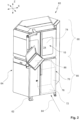
- Fig. 2 illustrates, using a perspective view, a manufacturing system designated overall by 60, which houses a machine tool 10, which is approximately according to Fig. 1 is designed.
- the manufacturing system 60 includes a frame 62 and an enclosure 64 designed like a cabinet in the exemplary embodiment.
- the enclosure 64 can also be referred to as a housing.
- the enclosure 64 is designed to be approximately man-high.
- the manufacturing system 60 is designed to be compact, with the manufacturing system 60 having a layout that is comparable to a tall cabinet. This is not to be understood as limiting.
- the frame 62 can also be referred to as the base frame of the manufacturing system 60.
- the in is again on or on the frame 62 Fig. 1 illustrated frame 12 (also: machine tool frame) of the machine tool 10 is arranged.
- the design of the manufacturing system 60 shown includes a lower part 66 and an upper part 68 arranged thereon, which, for example, accommodate different assemblies of the manufacturing system 60 and spatially separate them from one another.
- the manufacturing system 60 includes a device 70 for chip removal.
- the device 70 can also be referred to as a chip removal device.
- the lower part 66 houses the device 70.
- the device 70 provides a chip cart parking space 72 (in Fig. 2 indicated by dashed lines) ready for a chip cart.
- the device 70 can be closed by a door 76 of the housing 64.
- the machine tool 10 (or its working space 24) can be closed by a door 78 of the housing 64.
- the machine tool 10 is assigned with its working space 24 to the upper part 68 of the manufacturing system 60.
- the machine tool 10 is thus arranged at a favorable height for a standing or sitting operator.
- the device 70 for chip removal is assigned to the lower part 66 of the manufacturing system 60.
- the device 70 is arranged below the working space 24 of the machine tool 10.
- FIG. 2 A front side of the manufacturing system 60 or the machine tool 10 is indicated by an arrow labeled 84.
- An operator who operates the manufacturing system 60 at the front 84 can, for example, observe and operate the machine tool 10 and the chip removal device 70 via the doors 76, 78.
- a control console designated 86 for controlling the manufacturing system 60 is shown, which also faces the front 84.
- the control console 86 is assigned to the control device 18 and/or coupled to it.
- the compactness of the machine tool 10 and the manufacturing system 60 provided with it simplifies operation. Relevant components of the manufacturing system 60 can be viewed and accessed by the operator at the front 84.
- the cabinet-like design with the lower part 66 and the upper part 68 allows the chip cart parking space 72 to be arranged below the work space 24; this also applies when viewed along the vertical (compare the arrow Z in the X-Y-Z coordinate system). Viewed from above, the work space 24 partially or completely obscures the chip cart parking space 72, at least in exemplary embodiments.
- the Figures 3-5 illustrate further components of the device 70 and their interaction with the machine tool 10.
- the Figures 2-5 show the manufacturing system 60 or components thereof from the same perspective (from obliquely above on the front 84).
- the enclosure 64 is closed.
- Fig. 3 at least the doors 76 and 78 of the enclosure 64 are open.
- the door 78 is open, the working space 24 of the machine tool 10 is accessible to an operator arranged at the front 84.
- the workpiece holder 30 and the tool holder 34 are arranged in the working space 24 and can be moved relative to one another.
- a chip cart 90 is placed at the chip cart parking space 72 and can be moved out of the chip cart parking space 72 if necessary. This is the case, for example, when the chip cart 90 is completely filled with chips and other abrasion.
- the chip cart 90 is at least partially arranged above a coolant trough 92 for holding cooling lubricants and the like. This can also refer to cooling lubricants or cooling lubricants (KSS) that are mixed with chips in the chip cart 90 and flow towards the KSS tray 92.
- KSS cooling lubricants
- the working space 24 of the machine tool 10 is connected to the chip cart 90 via a connecting piece 94.
- chips can be as possible fall directly from the work area 24 into the chip cart 90. This is preferably done by gravity and without an additional (driven) chip conveyor.
- a handle 98 is formed on the chip cart 90.
- the connecting piece 94 has a handle 102 and a locking element 104 for handling purposes.
- the chip cart 90 can be pulled out of the chip cart parking space 72 in the housing 64 using the handle 98.
- the handling elements allow the chip cart 90 to be changed or emptied quickly and easily.
- the chip cart 90 is arranged completely below the working space 24. This is made possible by the raised arrangement of the machine tool 10 in the upper part 68 of the housing 64. This is in turn made easier by the compact design of the machine tool 10.
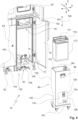
- Fig. 4 shows a partial view of the enclosure 64 with the door 76 opened to further illustrate components of the device 70.
- the chip cart 90 has moved out of the chip cart parking space 72 in the enclosure 64. This is possible when the connecting piece 94 is in a release position.
- the connecting piece 94 is vertically displaceable between the release position and an operating position, compare a double arrow labeled 106 in Fig. 4 .
- the handle 102 is used for handling. With the locking element 104, the connecting piece 94 can be locked or locked in the release position.
- the chip cart 90 provides a receptacle 110 for a chip basket 112.
- the chip basket 112 can be removed from the receptacle 110 in exemplary embodiments. Accordingly, the entire chip cart 90 can be changed if necessary, i.e. a full chip cart 90 can be replaced by an empty chip cart 90. However, it is also possible to simply change or empty the chip basket 112 when the chip cart 90 has moved out of the chip cart parking space 72.
- the chip basket 112 has an opening 114 through which chips can fall from the working space 24 into the chip basket 112. For this purpose, the chips pass through the connecting piece 94.
- at least one handle 116 is provided in the chip basket 112 in the exemplary embodiment, so that the chip basket 112 can also be handled separately.
- the chip carriage 90 has a chassis 120 at its lower end, which carries a structure 122.
- the structure 122 surrounds the receptacle 110. In the area of the receptacle 110 for the chip basket 112, the structure 122 is approximately box-shaped and opened upwards.
- the handle 98 is attached to the structure 122.
- the recording 110 is arranged above a coolant handling section 126.
- the coolant handling section 126 is arranged between the chassis 120 and the receptacle 110.
- a coolant discharge line 128 is arranged in the coolant handling section 126, via which excess cooling lubricant can drip or flow away from the chip basket 112 in the direction of the coolant trough 92.
- the coolant handling section 126 includes an operating opening 130, via which at least the coolant discharge line 128 is accessible, which in the exemplary embodiment includes a quick coupling 132.
- the structure 122 of the chip cart 90 has a rear frame recess 136. This allows a favorable arrangement of the chip cart 90 in relation to the coolant trough 92 in the housing 64 of the manufacturing system 60.
- the chip cart 90 In the direction of the connecting piece 94, the chip cart 90 has a circumferential edge 140, which is separated from the connecting piece 94 in the operating position (see Fig. 9 ) is contacted in order to couple the chip cart 90 sufficiently tightly to the work space 24 for chip removal.
- the KSS tub 92 is in Fig. 4 arranged in an underfloor parking space 142.
- the coolant trough 92 is arranged in particular below the chip basket 112 when the chip cart 90 is placed in the chip cart parking space 72.
- the KSS trough 92 is mounted on a chassis 144 and can therefore be moved out of the underfloor parking space 142. This is simplified by a handle 146.
- the KSS trough 92 has a KSS line 148, which can be coupled to the KSS discharge line 128 when the KSS trough 92 and the chip cart 90 are arranged at their respective storage locations 72, 142.
- the KSS trough includes a KSS container 150, into which the KSS line 148 flows. Compared to the chip basket 112, the coolant container 150 is flatter but has a larger base area. In this way, both the chip basket 112 and the coolant container 150 have sufficient holding capacities.
- FIG. 5 The representation in Fig. 5 is based on the representations in accordance with Figures 2-4 , where in Fig. 5 the enclosure 64 is not shown.
- the work space 24 of the machine tools 10 and a work space cladding 156 surrounding it are at least partially shown.
- the working space 24 has a chip removal opening 158, which in the exemplary embodiment is designed as a chip funnel at a lower end of the working space cladding 156.
- the connecting piece 94 couples to the chip removal opening 158 and surrounds it at least in sections.
- the connecting piece 94 carries a seal 160 at its end facing the chip carriage 90, which is in the operating position (see Fig. 9 ) rests on the peripheral edge 140 of the chip cart 90. This allows a sufficiently tight connection between the connecting piece 94 and the chip cart 90. It goes without saying that the seal 160 could in principle also be arranged on the chip cart 90.
- the coolant trough 92 with the coolant container 150 can be functionally connected via the coolant line 148 to the coolant discharge line 128 in the coolant handling section 126 of the chip cart 90.
- the coolant container 150 is designed to be U-shaped at least in sections (in plan view), so that the coolant container 150 surrounds at least one recess 166 into which the chassis 120 of the chip cart 90 can enter (for example with a track on one side).
- the chassis 120 of the chip carriage 90 is designed to be U-shaped in plan view, with the coolant container 150 also being designed to be U-shaped in plan view, but with the orientation pivoted by 180°.
- the two “U-shapes” can therefore move into one another. This reduces the vertical space required.
- the coolant trough 92 includes guides 168 for the chassis 120 of the chip cart 90.
- the coolant container 150 forms at least part of the chip cart parking space 72 in the exemplary embodiment.
- Fig. 5 170 indicates a fill level indicator for the coolant container.
- side guides 174 for the KSS tray 92 are also shown, which are firmly connected to the frame 62 (in Fig. 5 not shown) are connected and form a boundary of the underfloor parking space 142 for the coolant tub 92.
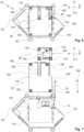
- FIGs 6 and 7 show vertical views (from below) of the manufacturing system 60 with the chip cart 90 and the coolant tray 92.
- the chip cart 90 and the coolant tub 92 are arranged in their respective parking spaces 72, 142.
- the chip cart 90 and the coolant trough 92 are integrated into the housing 64 accommodated on the frame 62 or housed (enclosed or covered) by it.
- Fig. 7 With the door 76 open, the chip cart 90 and the coolant tub 92 have been moved out of their parking spaces 72, 142. This is done at the front of the manufacturing system 60, compare the arrow 84 in Fig. 2 .
- the chassis 120 of the chip carriage 90 has four rollers 178 which form a surface 182, compare Fig. 6 .
- the chassis 144 of the KSS trough has four rollers 180, which form a surface 184.
- the surfaces 182, 184 are defined, for example, by the respective coupling points of the rollers 178, 180 with the chassis 120, 144.
- the surfaces 182, 184 are oriented horizontally.
- the surface 182 of the chip cart 90 is at least partially (or possibly completely) arranged within the surface 184 of the coolant trough 92. This illustrates the interlaced (or possibly overlapping) design with favorable use of the given installation space (footprint of the manufacturing system 60).
- Fig. 7 illustrates the guides 168 that the KSS trough provides for the chassis 120 of the chip carriage 90. Furthermore, the recess 166 is shown, which is formed in the coolant container 150. Two rollers 178 of the chassis 120 of the chip carriage 90 arranged one behind the other can retract there. Further illustrated Fig. 7 the guides 174 for the coolant tub coupled to the frame 62. The guides 174 limit the underground parking space 142. In Fig. 7 A double arrow marked 186 illustrates the respective direction of travel of the chip carriage 90 and the coolant trough 92 when retracting and extending.
- the Figures 8 and 9 illustrate the release position using cut-out illustrations ( Fig. 8 ) and the operating position ( Fig. 9 ) of the connecting piece 94.
- the connecting piece 94 is arranged above the chip carriage 90 and below the working space 24, compare the vertical Z-axis in Fig. 9 .
- the chip removal opening 158 of the work space opens into the connecting piece 94.
- An edge 188 of the connecting piece 94 surrounds or overlaps the chip removal opening 158.
- an intermediate piece 190 is also provided, which is part of the chip removal opening 158.
- the chip removal opening 158 is approximately funnel-shaped overall and tapers towards the chip carriage 90.
- the locking element 104 is accommodated on the connecting piece 94, which is in Fig. 8 is engaged in a recess 192 of the chip removal opening 158 or the intermediate piece 190. In this way, the connecting piece 94 is in the in Fig. 8 secured in the release position shown. In the in Fig. 9 In the operating position shown, the locking element 104 is disengaged from the recess 192. In this state, the connecting piece 94 can be moved vertically (compare the double arrow 106). Due to its own weight, the connecting piece 94 can move towards the chip cart 90. The movement can also take place via the handle 102. The connecting piece 94 forms a channel 194 for chip transfer. In the exemplary embodiment according to Figures 8 and 9 In order to simplify the vertical adjustment movement, a lifting guide 196 is provided, via which the connecting piece 94 is guided in a vertically displaceable manner on the frame side.
- a collar 202 is provided at the connecting piece 94, in particular a circumferential collar 202.
- the collar 202 carries the seal 160.
- the connecting piece 94 with the seal 160 lies sufficiently close to the peripheral edge 140 of the chip carriage 90.
- a (lower) mouth 204 of the connecting piece 94 is at least partially engaged in the opening 114 of the chip basket 112. In this way it is ensured that chips are safely guided along the channel 194 through the connecting piece 94 into the chip basket 112 of the chip cart 90 along a chip removal path 210 between the working space 24 and the chip cart 90.
Landscapes
- Engineering & Computer Science (AREA)
- Mechanical Engineering (AREA)
- Machine Tool Units (AREA)
- Handcart (AREA)
- Auxiliary Devices For Machine Tools (AREA)
Applications Claiming Priority (1)
| Application Number | Priority Date | Filing Date | Title |
|---|---|---|---|
| DE102022123232.8A DE102022123232B4 (de) | 2022-09-12 | 2022-09-12 | Vorrichtung zur Späneabführung für eine Werkzeugmaschine und Fertigungssystem |
Publications (1)
| Publication Number | Publication Date |
|---|---|
| EP4335585A1 true EP4335585A1 (fr) | 2024-03-13 |
Family
ID=88016197
Family Applications (1)
| Application Number | Title | Priority Date | Filing Date |
|---|---|---|---|
| EP23196126.9A Pending EP4335585A1 (fr) | 2022-09-12 | 2023-09-08 | Dispositif d'évacuation de copeaux pour machine-outil et système de fabrication |
Country Status (4)
| Country | Link |
|---|---|
| US (1) | US20240082972A1 (fr) |
| EP (1) | EP4335585A1 (fr) |
| CN (1) | CN117681032A (fr) |
| DE (1) | DE102022123232B4 (fr) |
Families Citing this family (2)
| Publication number | Priority date | Publication date | Assignee | Title |
|---|---|---|---|---|
| US12179299B2 (en) * | 2018-08-07 | 2024-12-31 | Illinois Tool Works Inc. | Machine tool with recirculating coolant filtration system |
| CN118832436B (zh) * | 2024-09-24 | 2024-11-15 | 烟台南工大环球智能装备有限公司 | 一种数控回转工作台 |
Citations (7)
| Publication number | Priority date | Publication date | Assignee | Title |
|---|---|---|---|---|
| US20060045641A1 (en) * | 2004-08-27 | 2006-03-02 | Ford Motor Company | Machining system with integrated chip hopper |
| EP2394778A1 (fr) | 2010-06-10 | 2011-12-14 | Maschinenfabrik Berthold Hermle Aktiengesellschaft | Centre de traitement vertical ayant la forme d'un portique ou d'un support mobile doté d'une ouverture au sol pour l'évacuation des résidus de traitement à partir de l'espace de travail du centre de traitement |
| DE102016205234A1 (de) * | 2016-03-30 | 2017-10-05 | Gdw Werkzeugmaschinen Gmbh | Drehmaschine |
| US20190084102A1 (en) | 2016-04-19 | 2019-03-21 | Haute Ecole Arc | Five axis machine tool |
| CN110170669A (zh) * | 2019-06-24 | 2019-08-27 | 彭亚莉 | 一种床身底部出废料的车床废料接料扩展机构 |
| WO2021033430A1 (fr) * | 2019-08-22 | 2021-02-25 | スター精密株式会社 | Tour et procédé d'évacuation de copeaux à partir de celui-ci |
| DE202022102029U1 (de) * | 2022-04-14 | 2022-05-03 | Starrag Gmbh | Vorrichtung zur Erfassung der Position eines Auffangbehälters |
Family Cites Families (55)
| Publication number | Priority date | Publication date | Assignee | Title |
|---|---|---|---|---|
| US2691312A (en) * | 1950-09-20 | 1954-10-12 | Ex Cell O Corp | Boring and turning machine and fixture for generating various predetermined surfacesof revolution |
| US3708238A (en) * | 1970-12-03 | 1973-01-02 | Speed Fastener Inc | Alignment jig for electric screw driver or the like |
| US3958893A (en) * | 1974-09-10 | 1976-05-25 | Boyajian Alfred | Drill guide |
| US4281457A (en) * | 1979-10-17 | 1981-08-04 | Black & Decker Inc. | Vacuum-operated cutting tool and system therefor |
| US4310270A (en) * | 1980-02-08 | 1982-01-12 | The Cross Company | Feed unit |
| JPS5717710U (fr) * | 1980-07-05 | 1982-01-29 | ||
| US4685361A (en) * | 1980-10-20 | 1987-08-11 | The Warner & Swasey Company | Machine tool |
| JPS60157162U (ja) * | 1984-03-28 | 1985-10-19 | セイコ−精機株式会社 | 小形研削盤 |
| US5052411A (en) * | 1988-08-26 | 1991-10-01 | Arnold Schoolman | Vacuum barrier attachment for medical equipment |
| US5702294A (en) * | 1989-06-19 | 1997-12-30 | Constant Velocity Systems, Inc. | Grinding bit having a novel grinding grip |
| DE4441253A1 (de) * | 1994-11-19 | 1996-05-23 | Hermle Berthold Maschf Ag | Werkzeugmaschine, insbesondere Bohr- und Fräsmaschine |
| WO1998004383A1 (fr) * | 1996-07-29 | 1998-02-05 | Matsushita Electric Industrial Co., Ltd. | Machine-outil |
| EP0913228B1 (fr) * | 1997-03-31 | 2003-01-08 | Makino Milling Machine Co. Ltd. | Machine outil |
| US6138818A (en) * | 1998-11-23 | 2000-10-31 | Green Technologies Inc. | Workpiece inversion system for milling machines |
| US6588738B1 (en) * | 1999-07-23 | 2003-07-08 | Lillbacka Jetair Oy | Laser cutting system |
| EP1116548A3 (fr) * | 2000-01-17 | 2002-04-17 | Toyoda Koki Kabushiki Kaisha | Machine-outil à broche principale verticale et son procédé de fabrication |
| FR2816230B1 (fr) * | 2000-11-08 | 2003-03-07 | Greffioz Andre | Machine-outil a plusieurs axes |
| JP4441107B2 (ja) * | 2000-12-01 | 2010-03-31 | 住友化学株式会社 | 切断装置 |
| AUPR566401A0 (en) * | 2001-06-13 | 2001-07-12 | Terpstra Enterprises Pty Ltd | Extraction apparatus |
| US6916236B2 (en) * | 2001-06-13 | 2005-07-12 | Terpstra Enterprises Pty Ltd. | Extraction apparatus |
| JP4392203B2 (ja) * | 2003-07-15 | 2009-12-24 | 株式会社森精機製作所 | 工作機械 |
| DE102005000737A1 (de) * | 2005-01-04 | 2006-07-20 | P & L Gmbh & Co.Kg | Werkzeugmaschinentisch |
| US8869786B2 (en) * | 2008-07-03 | 2014-10-28 | Mitch Faiweather | Chop saw with dust collection system |
| US10543622B2 (en) * | 2008-07-03 | 2020-01-28 | JPL Global, LLC | Rotatable filter system and methodology |
| US20100058911A1 (en) * | 2008-09-11 | 2010-03-11 | Jay Aaron Goddard | Blade Guard for Power Tool Having an Evacuation System |
| JP5235610B2 (ja) * | 2008-10-27 | 2013-07-10 | 株式会社森精機製作所 | 工作機械の加工粉排出装置 |
| US8506216B2 (en) * | 2009-03-31 | 2013-08-13 | Komatsu Ntc Ltd. | Horizontal machine tool |
| WO2012111170A1 (fr) * | 2011-02-17 | 2012-08-23 | 株式会社牧野フライス製作所 | Machine-outil |
| JP6062325B2 (ja) * | 2013-06-26 | 2017-01-18 | Dmg森精機株式会社 | 工作機械の切屑処理装置 |
| CN106429104B (zh) * | 2014-12-05 | 2018-10-23 | 贵州金雕天宇创新科技有限公司 | 一种收集箱 |
| KR101634975B1 (ko) * | 2015-05-14 | 2016-07-05 | 김산 | 절삭칩과 절삭유 자동 연속 분리장치 |
| US10239136B2 (en) * | 2015-08-31 | 2019-03-26 | JPL Global, LLC | Circular saw apparatus with integrated multistage filtration system |
| KR101615863B1 (ko) * | 2015-10-23 | 2016-04-27 | 임영호 | 칩 컨베이어장치 |
| US11890737B2 (en) * | 2015-12-28 | 2024-02-06 | Peter Justin Merello | Overhead drill and anchor press |
| CN105880641A (zh) * | 2016-06-14 | 2016-08-24 | 慈溪市小旋风数控机械有限公司 | 后置式送料数控车床 |
| US11407074B2 (en) * | 2016-09-14 | 2022-08-09 | Fuji Corporation | Processing machine line |
| CN106392340B (zh) * | 2016-09-25 | 2018-03-16 | 郑招才 | 一种激光打孔废料收集机构 |
| GB201616363D0 (en) * | 2016-09-27 | 2016-11-09 | Black & Decker Inc | Dust extractor with flat back |
| CN106363457B (zh) * | 2016-11-17 | 2018-07-24 | 江门市瑞和铸造有限公司 | 一种铣床 |
| US10780541B2 (en) * | 2017-09-08 | 2020-09-22 | G.A.W. Inc. | Vacuum dust extraction apparatus for a percussive air tool |
| JP6581170B2 (ja) * | 2017-12-13 | 2019-09-25 | ファナック株式会社 | 工作機械 |
| DE102019200663A1 (de) * | 2018-08-30 | 2020-03-05 | Deckel Maho Pfronten Gmbh | Transporteinrichtung zum transportieren einer oder mehrerer handhabungseinrichtungen |
| CN109604666B (zh) * | 2018-12-17 | 2020-07-21 | 浙江西菱股份有限公司 | 一种钻床 |
| CN109396944A (zh) * | 2018-12-20 | 2019-03-01 | 惠阳佑鑫金属制品有限公司 | 负压式吸屑分离机构 |
| CN110039369B (zh) * | 2019-05-30 | 2021-03-16 | 西安航空职业技术学院 | 一种数控立式铣床用废屑清理装置及其使用方法 |
| KR102585380B1 (ko) * | 2019-08-05 | 2023-10-05 | 장지아강 란위 트레이드 컴퍼니 리미티드 | 필터장치와 절삭액 필터시스템 |
| WO2021036003A1 (fr) * | 2019-08-23 | 2021-03-04 | 苏州龙辉金属表面科技有限公司 | Taraudeuse de type à table |
| CN111186163A (zh) * | 2019-11-28 | 2020-05-22 | 天门市金兴达汽车零部件有限公司 | 一种汽车零部件加工用铁屑回收装置 |
| CN111112752A (zh) * | 2020-02-18 | 2020-05-08 | 重庆康铖智汇机械制造有限公司 | 一种零部件切割装置 |
| CN111347283A (zh) * | 2020-03-31 | 2020-06-30 | 东莞市嘉宏机电科技有限公司 | 一种机床自动排屑装置 |
| CN111730404B (zh) * | 2020-07-09 | 2021-08-13 | 常州庆源机械科技有限公司 | 一种便于辅助集屑的铣床 |
| CN112171360B (zh) * | 2020-09-17 | 2022-09-06 | 苏州市博力精密塑胶模具有限公司 | 一种数控铣床 |
| DE102021113892B4 (de) * | 2021-05-28 | 2024-05-16 | Chiron Group Se | Kombinierte Transfer- und Speichervorrichtung sowie Anlage zur spanenden Fertigung |
| DE102022109735B4 (de) * | 2022-04-22 | 2023-12-21 | Chiron Group Se | Werkzeugmaschine mit Schutzbalg |
| EP4545252A1 (fr) * | 2023-09-27 | 2025-04-30 | Nanjing Chervon Industry Co., Ltd. | Outil d'impact |
-
2022
- 2022-09-12 DE DE102022123232.8A patent/DE102022123232B4/de active Active
-
2023
- 2023-09-07 CN CN202311150349.9A patent/CN117681032A/zh active Pending
- 2023-09-08 EP EP23196126.9A patent/EP4335585A1/fr active Pending
- 2023-09-12 US US18/367,018 patent/US20240082972A1/en active Pending
Patent Citations (7)
| Publication number | Priority date | Publication date | Assignee | Title |
|---|---|---|---|---|
| US20060045641A1 (en) * | 2004-08-27 | 2006-03-02 | Ford Motor Company | Machining system with integrated chip hopper |
| EP2394778A1 (fr) | 2010-06-10 | 2011-12-14 | Maschinenfabrik Berthold Hermle Aktiengesellschaft | Centre de traitement vertical ayant la forme d'un portique ou d'un support mobile doté d'une ouverture au sol pour l'évacuation des résidus de traitement à partir de l'espace de travail du centre de traitement |
| DE102016205234A1 (de) * | 2016-03-30 | 2017-10-05 | Gdw Werkzeugmaschinen Gmbh | Drehmaschine |
| US20190084102A1 (en) | 2016-04-19 | 2019-03-21 | Haute Ecole Arc | Five axis machine tool |
| CN110170669A (zh) * | 2019-06-24 | 2019-08-27 | 彭亚莉 | 一种床身底部出废料的车床废料接料扩展机构 |
| WO2021033430A1 (fr) * | 2019-08-22 | 2021-02-25 | スター精密株式会社 | Tour et procédé d'évacuation de copeaux à partir de celui-ci |
| DE202022102029U1 (de) * | 2022-04-14 | 2022-05-03 | Starrag Gmbh | Vorrichtung zur Erfassung der Position eines Auffangbehälters |
Also Published As
| Publication number | Publication date |
|---|---|
| DE102022123232A1 (de) | 2024-03-14 |
| US20240082972A1 (en) | 2024-03-14 |
| DE102022123232B4 (de) | 2025-10-02 |
| CN117681032A (zh) | 2024-03-12 |
Similar Documents
| Publication | Publication Date | Title |
|---|---|---|
| DE102009048863B4 (de) | Werkstück-Umsetz-Robotersystem | |
| DE4409532C2 (de) | Handhabungssystem | |
| DE102005043602B4 (de) | Zahnradbearbeitungsmaschine sowie Verfahren zum Betrieb einer solchen Zahnradbearbeitungsmaschine | |
| DE3721610C2 (fr) | ||
| EP4335585A1 (fr) | Dispositif d'évacuation de copeaux pour machine-outil et système de fabrication | |
| DE102009048757A1 (de) | Vorrichtung zur Feinbearbeitung von optisch wirksamen Flächen an Werkstücken, insbesondere Brillengläsern | |
| EP1827754B1 (fr) | Cellule servant au montage d' ensembles de pièces sur des palettes et procédé pour faire fonctionner ladite cellule | |
| DE602004012302T2 (de) | Laserschneidanlage mit werkstückträger mit parallelbeabstandeten gitterelementen und teilentladungseinheit mit einem paar einander gegenüberliegender gabelanordnungen | |
| CH657801A5 (de) | Bearbeitungsvorrichtung. | |
| DE202013012320U1 (de) | Honmaschine mit mehreren Arbeitsstationen und Rundtisch | |
| EP2753454B1 (fr) | Machine-outil | |
| DE602004006482T2 (de) | Rundschleifmaschine | |
| EP1718435B1 (fr) | Machine d'usinage pour usiner des pieces | |
| DE102006050425B4 (de) | Vorrichtung zum Fräsen und Drehen sowie Verfahren zum Bearbeiten eines Linsenrohlings | |
| EP3740344B1 (fr) | Machine-outil pour usinage de pièces par enlèvement de copeaux et procédé de changement de palette sur une machine-outil | |
| DE102011053467A1 (de) | Werkzeugmaschine und Verfahren zum Werkzeugwechsel | |
| EP0331178A1 (fr) | Construction compacte d'une perceuse sur colonne | |
| DE102010062671B3 (de) | Werkzeugmaschine zur Bearbeitung von Werkstücken | |
| DE102019124034B4 (de) | Werkzeugmaschine mit Werzeugwechselmagazin und zugeordnetem Werkzeugspeichermagazin | |
| DE102005016510A1 (de) | Vorrichtung zum spanabhebenden Bearbeiten von gehärteten Werkstücken | |
| EP1759815B1 (fr) | Agencement de robot comprenant un robot placé sur un bâti | |
| DE102007044288A1 (de) | Werkzeugmaschine mit einem ersten und einem zweiten Werkstückträger und Werkstückbearbeitungsverfahren | |
| DE102011050959A1 (de) | Werkzeugmaschine und Verfahren für eine Werkzeugmaschine | |
| DE10354706C5 (de) | Werkzeugmaschine mit Transportvorrichtung | |
| AT402619B (de) | Fertigungsanlage mit parallel- und fertigungsanlage mit parallel- und nebenförderwegen nebenförderwegen |
Legal Events
| Date | Code | Title | Description |
|---|---|---|---|
| PUAI | Public reference made under article 153(3) epc to a published international application that has entered the european phase |
Free format text: ORIGINAL CODE: 0009012 |
|
| STAA | Information on the status of an ep patent application or granted ep patent |
Free format text: STATUS: THE APPLICATION HAS BEEN PUBLISHED |
|
| AK | Designated contracting states |
Kind code of ref document: A1 Designated state(s): AL AT BE BG CH CY CZ DE DK EE ES FI FR GB GR HR HU IE IS IT LI LT LU LV MC ME MK MT NL NO PL PT RO RS SE SI SK SM TR |
|
| STAA | Information on the status of an ep patent application or granted ep patent |
Free format text: STATUS: REQUEST FOR EXAMINATION WAS MADE |
|
| 17P | Request for examination filed |
Effective date: 20240912 |
|
| RBV | Designated contracting states (corrected) |
Designated state(s): AL AT BE BG CH CY CZ DE DK EE ES FI FR GB GR HR HU IE IS IT LI LT LU LV MC ME MK MT NL NO PL PT RO RS SE SI SK SM TR |