EP4335591A1 - Outil d'impact avec enclume fendue - Google Patents
Outil d'impact avec enclume fendue Download PDFInfo
- Publication number
- EP4335591A1 EP4335591A1 EP23194910.8A EP23194910A EP4335591A1 EP 4335591 A1 EP4335591 A1 EP 4335591A1 EP 23194910 A EP23194910 A EP 23194910A EP 4335591 A1 EP4335591 A1 EP 4335591A1
- Authority
- EP
- European Patent Office
- Prior art keywords
- anvil portion
- external
- internal
- anvil
- splines
- Prior art date
- Legal status (The legal status is an assumption and is not a legal conclusion. Google has not performed a legal analysis and makes no representation as to the accuracy of the status listed.)
- Pending
Links
Images





Classifications
-
- B—PERFORMING OPERATIONS; TRANSPORTING
- B25—HAND TOOLS; PORTABLE POWER-DRIVEN TOOLS; MANIPULATORS
- B25D—PERCUSSIVE TOOLS
- B25D17/00—Details of, or accessories for, portable power-driven percussive tools
- B25D17/06—Hammer pistons; Anvils ; Guide-sleeves for pistons
-
- B—PERFORMING OPERATIONS; TRANSPORTING
- B25—HAND TOOLS; PORTABLE POWER-DRIVEN TOOLS; MANIPULATORS
- B25B—TOOLS OR BENCH DEVICES NOT OTHERWISE PROVIDED FOR, FOR FASTENING, CONNECTING, DISENGAGING, OR HOLDING
- B25B21/00—Portable power-driven screw or nut setting or loosening tools; Attachments for drilling apparatus serving the same purpose
- B25B21/02—Portable power-driven screw or nut setting or loosening tools; Attachments for drilling apparatus serving the same purpose with means for imparting impact to screwdriver blade or nut socket
- B25B21/026—Impact clutches
-
- B—PERFORMING OPERATIONS; TRANSPORTING
- B25—HAND TOOLS; PORTABLE POWER-DRIVEN TOOLS; MANIPULATORS
- B25B—TOOLS OR BENCH DEVICES NOT OTHERWISE PROVIDED FOR, FOR FASTENING, CONNECTING, DISENGAGING, OR HOLDING
- B25B21/00—Portable power-driven screw or nut setting or loosening tools; Attachments for drilling apparatus serving the same purpose
- B25B21/02—Portable power-driven screw or nut setting or loosening tools; Attachments for drilling apparatus serving the same purpose with means for imparting impact to screwdriver blade or nut socket
-
- B—PERFORMING OPERATIONS; TRANSPORTING
- B25—HAND TOOLS; PORTABLE POWER-DRIVEN TOOLS; MANIPULATORS
- B25D—PERCUSSIVE TOOLS
- B25D2217/00—Details of, or accessories for, portable power-driven percussive tools
- B25D2217/0011—Details of anvils, guide-sleeves or pistons
- B25D2217/0015—Anvils
-
- B—PERFORMING OPERATIONS; TRANSPORTING
- B25—HAND TOOLS; PORTABLE POWER-DRIVEN TOOLS; MANIPULATORS
- B25D—PERCUSSIVE TOOLS
- B25D2250/00—General details of portable percussive tools; Components used in portable percussive tools
- B25D2250/105—Exchangeable tool components
Definitions
- Impact tools are power tools configured to deliver a high torque output by storing energy in a rotating mass and delivering it suddenly through an output shaft to a fastener.
- Impact tool anvils provide an interface between an impact tool hammer and a socket used to tighten the fastener. As impact tools become more powerful, sizing standards limit what can be done to strengthen the anvils, resulting in premature wear and breakage of the anvils.
- Impact tools e.g., impact wrenches, etc.
- a rotating mass e.g., a hammer
- impact tools have become more powerful, yet sizing standards (which ensure tool to socket compatibility) have limited what can be done to strengthen the anvil components, such as square ends located at an output end of the anvils. These limitations have resulted in increased instances of premature wear and breakage of anvils, resulting in a loss of transmittable torque or the tool being rendered unusable.
- impact tools must be disassembled in order to replace the broken or worn anvils, causing time delays, especially when the impact tool is returned to the manufacturer or a third party maintenance provider for service.
- the impact tool described herein includes a split anvil assembly having at least a first half and a second half, or an internal anvil portion fixed inside a housing of the impact tool and an external anvil portion that extends outside the housing of the impact tool.
- the external anvil portion is removably connected to the internal anvil portion and may be disengaged from the external anvil portion and completely removed from the housing.
- the external anvil portion may be selected from a plurality of replaceable anvil attachments, including but not limited to anvils with different drive sizes, socket extensions, custom sockets, etc. that are interchangeable without disassembling the impact tool.
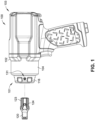
- FIG. 1 shows an illustrative embodiment of an impact tool assembly 100 in accordance with the present disclosure.
- the impact tool assembly 100 includes a housing 102 having a front end 101 and a rear end 103.
- the housing 102 houses an impact assembly 110 that includes a drive mechanism 105 which rotates a hammer 106 of the impact assembly 110 around an output axis 100A.
- the output axis 100A extends from the front end 101 to the rear end 103.
- the impact tool assembly 100 includes a hammercase 104 that houses an impact assembly 110.
- the impact tool assembly 100 may further include a gear set assembly 107 housed within the housing 102 connecting the drive assembly 105 with the hammer 106.
- the drive mechanism 105 comprises a pneumatic (compressed air) motor powered by a source of compressed air (not shown).
- a source of compressed air not shown
- the impact tool 100 may also include an electric motor powered by a power source such as a removable battery, an internal battery, an external power source via an electric cord, combinations thereof, or the like.
- the hammer 106 includes at least one hammer jaw 112.
- the impact assembly 110 further includes a split anvil assembly 115 including an external anvil portion 120 and an internal anvil portion 130 , where the internal anvil portion 130 is retained inside the hammercase 104 and the external anvil portion 120 is removably attached to the internal anvil portion 130 in the hammercase 104.
- the external anvil portion 120 extends longitudinally from the front end 101 outside of the hammercase 104 and the housing 102.
- the internal anvil portion 130 includes at least one anvil jaw 132 configured to be repeatedly struck by the at least one hammer jaw 112 and rotate around the axis 100A.
- An output shaft 125 extends from the external anvil portion 120 and may receive a connector, a socket, or other device that engages a workpiece such as a fastener (e.g., a bolt, a nut, a screw, etc.) to be tightened or loosened.
- a fastener e.g., a bolt, a nut, a screw, etc.
- the hammercase 104 includes a bushing 114 and a ring 116 for holding the internal anvil portion 130 in place.
- the bushing 114 , the cover 116 , and the internal anvil portion 130 respectively include access ports 131 disposed on the surface of the bushing 114 , the ring 116 , and the internal anvil portion 130 , respectively.
- the access ports 131 comprise through holes that extend from an outside surface to an inside surface of the bushing 114 , the ring 116 , and the internal anvil portion 130 , and are aligned with each other.
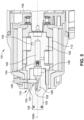
- the internal anvil portion 130 defines an internal anvil portion cavity 135 that receives the external anvil portion 120.
- the internal anvil portion cavity 135 may further define an opening that may be used for accessing components within the hammercase 104 and/or the impact assembly 110 that may otherwise be inaccessible without the disassembly of the impact tool 100.
- the internal anvil portion cavity 135 may further define a lubrication passage 140 and at least one lubrication channel 142.
- a lubrication port 144 is disposed within the internal anvil portion cavity 135 at an opening of the lubrication passage 140. It should be understood that in other embodiments, the internal anvil portion cavity 135 may not include a lubrication passage or any other opening allowing the user to access the internal components of the impact assembly 110.
- the external anvil portion 120 defines an external anvil portion cavity 126 including a retaining cavity 128 , and a retaining orifice 121.
- the external anvil portion cavity 126 houses at least a portion of a retractable pin 124.
- the retractable pin 124 is configured to engage with the access port 131 of the internal anvil portion 130 , thereby effectively locking the external anvil portion 120 and the internal anvil portion 130.
- the retractable pin 124 limits rotational displacement in relation to axis 100A and limits longitudinal displacement along axis 100A between the external anvil portion 120 and the internal anvil portion 130.
- the external anvil portion 120 Upon retraction of the retractable pin 124 , the external anvil portion 120 disengages with the internal anvil portion 130 , allowing the external anvil portion 120 to be removed from the internal anvil portion cavity 135. The external anvil portion 120 disengages from the impact tool assembly 100 , thereby exposing the internal anvil portion cavity 135.
- the retaining cavity 128 houses a biasing member 122 that retains the retaining pin 124 within the retaining orifice 121.
- the biasing member 122 biases the retaining pin 124 outward towards the access port 131 of the internal anvil portion 130 , locking the two portions of the split anvil assembly 115 together.
- the retaining pin 124 may be depressed with an elongated tool (not shown) until the retaining pin 124 is fully depressed out of the access port 131.
- the output shaft 125 of the split anvil 115 can be replaced by inserting an appropriately sized elongated tool (e.g., a screwdriver) through the access port 131 and depressing the retaining pin 124.
- the impact tool assembly 100 includes a button 136 that actuates the retaining pin 124 and moves it between an engaged position and a disengaged position.
- the button 136 is a push button disposed on the ring 116.
- the retaining pin 124 In the engaged position, the retaining pin 124 is engaged with the access port 131 of the internal anvil portion 130, and securing the external anvil portion 120 from movement relative to the internal anvil portion 130.
- the retaining pin 124 In the disengaged position, the retaining pin 124 is pushed into the retaining cavity 126 , effectively disengaging the retaining pin 124 from the access port 131 of the internal anvil portion 130.
- the external anvil portion 120 may be fully disengaged and separated from the rest of the split anvil assembly 115 and the impact tool assembly 100.
- the external anvil portion 120 may be removably retained within the internal anvil assembly 130 using a retaining cap.
- the retaining cap may be secured, screwed, or fastened to the front end 101 of the hammercase 104.
- the retaining cap may be secured to an external surface of the ring 116 and cover at least a portion of the external anvil assembly 120.
- the retaining cap may be secured to the front end 101 of the hammercase 104 via a connector.
- the retaining cap may include at least one lug or projection configured to engage on an at least one notch (e.g., a cam path) of the ring 116.
- the retaining cap may be fully mated or coupled to the hammercase 104 by rotating the retaining cap in relation to axis 100A for at least a portion of a full three-hundred and sixty degree (360°) rotation.
- the external anvil portion 120 may be removably retained within the internal anvil portion 130 using a retractable ball detent mechanism.
- a retractable ball detent mechanism a ball disposed on a first half portion engages into a groove or notch disposed on a second half portion, effectively retaining the first half portion and second half portions together.
- the ball detent mechanism may be disposed on at least one of the external anvil portion 120 or the ring 116.
- the impact tool assembly 100 may include a retaining cap, such as the retainer cap discussed above.
- the retaining cap may include at least one retaining notch, configured to engage with and secure the ball disposed on the ring 116.
- the retaining cap may be biased in a direction away from the hammercase 104.
- a ball may be disposed within the external anvil portion cavity 126 or on an external surface of the external anvil portion 120.
- the ball may be biased against a notch disposed on the internal anvil portion cavity 135 and restrict rotational and axial movement between the external anvil portion 120 and the internal anvil portion 130.
- the ball may be biased against the internal anvil via a biasing mechanism such as, but not restricted to, a compression spring, a torsion spring, a spiral spring, a plate or leaf spring, or other biasing components.
- the ball may be formed of a metal, a polymer, a ceramic, or a combination thereof.
- the ball may be a steel ball.
- the ball detent mechanism may be actuated through an orifice disposed on the housing of the impact tool assembly 100.
- an orifice may be defined in the front end 101 of the impact tool assembly 100 , such as through the front face of the output shaft 125.
- the orifice may be disposed on the rear end 103 of the impact tool assembly 100.
- the orifice may define a borehole extending from the rear end 103 of the impact tool assembly to the ball detent mechanism disposed in the external anvil portion 120.
- the borehole is parallel with the axis 100A.
- the borehole may be coaxial and/or concentrically aligned with the axis 100A.
- the external anvil portion 120 may be removably retained within the internal anvil portion 130 using a friction ring or a hog ring.
- the friction ring may be coupled to the rear side of the external anvil portion 120.
- the friction ring compresses within the interior anvil portion cavity 135 until it reaches a friction ring notch defined on the surface of the interior anvil portion cavity 135.
- the friction ring expands, and the internal friction between the friction ring and the interior anvil portion cavity 135 holds the external anvil portion 120 secured to the internal anvil portion 130.
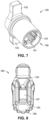
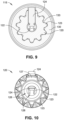
- the external anvil portion 120 includes external splines 123 defined around the circumference of the outer surface of the external anvil portion 120.
- the internal anvil portion 130 may also include internal splines 133 defined on an inner surface of the internal anvil portion cavity 135.
- the external splines 123 and the internal splines 133 may engage with each other, locking the external anvil portion 120 and restricting its rotation with respect with the internal anvil portion 130.
- the splines 123 and 133 allow for a transfer of the torque transmitted by the hammer 106 to the output shaft 125.
- the internal splines 131 and the external splines 123 are configured to engage with each other.
- the internal splines 131 and the external splines 123 may be shaped with square splines (tooth splines) or have differently shaped splines, including but not limited to radial slots, arc teeth, keyways, curvilinear splines, hex splines, and/or triple square splines.
- the external splines 123 and the internal splines 133 include at least one alignment spline tooth 127 and 137 , respectively.
- the at least one alignment spline tooth may, for example, have a larger thickness than a remaining of the external splines 123 and the remaining of the internal splines 133.
- the retaining orifice 121 and the internal anvil portion access port 131 are respectively defined on the alignment spline teeth 127 and 137 of the external splines 123 and internal splines 133.
- the alignment spline teeth 127 and 137 provide guidance when the external anvil portion 120 is engaged with the internal anvil portion 130 , in order to align the retaining orifice 121 of the external anvil portion 120 with the access ports 131 of the internal anvil portion 130 and other access ports 131 that may be defined in one or more of the hammercase 104 , the bushing 114 , and the ring 116. It should be understood that other types of alignment spline teeth may be used.
- the at least one alignment spline tooth 127 and the at least one alignment spline tooth 137 may have a different shape and/or a different size from than the remaining of the external splines 123 and the remaining of the internal splines 133 , respectively.
- the alignment spline teeth 127 and 137 may be thinner, taller, shorter, have a different spline radius, and/or a combination thereof.
- the external anvil portion 120 includes a pilot radius R P and a spline radius R S , where the pilot radius R P is the radius of a pilot of the external anvil portion with respect to the axis 100A and the spline radius R S is the radius of the external splines 123 with respect to the axis 100A.
- the pilot radius R P is larger than the spline radius R S
- the external anvil portion 120 is configured to disengage from the internal anvil portion 130 when the retractable pin 124 is depressed to a height that is at least one of equal to or less than the pilot radius R P of the external anvil 120.
- the difference in the radius decreases the amount of travel needed to disengage the retaining pin 124 from the access port 131 of the internal anvil portion 130. Further, having the spline radius R S be smaller also prevents the elongated tool used to depress the retaining pin 124 from catching on the external anvil portion 120 as it is removed.
- FIG. 11 shows different embodiments of the external anvil portion 120A, 120B, and 120C. These examples are not limiting and are used to show how the impact tool 100 having a split anvil assembly 115 may use interchangeable output shafts having different drive diameters, extended anvils, or accessories such as socket extensions and socket adapters.
- different embodiments of the external anvil portion 120 may have different sizes of output shaft 125.
- the output shaft 125 of external anvil portion 120 may range from one-quarter of an inch (1/4 in.) to two and one-half inches (2-1/2 in.).
- the output shaft may be sized for drive sizes of 1/4 in., 3/8 in., 1/2 in., 3/4 in., 1 in. 1-1/2 in., and 2-1/2 in. It should be understood that these drive sizes are examples and not limiting to any sizes in metric and/or imperial units.
Landscapes
- Engineering & Computer Science (AREA)
- Mechanical Engineering (AREA)
- Percussive Tools And Related Accessories (AREA)
Applications Claiming Priority (2)
| Application Number | Priority Date | Filing Date | Title |
|---|---|---|---|
| US202263404063P | 2022-09-06 | 2022-09-06 | |
| US18/239,362 US12440954B2 (en) | 2022-09-06 | 2023-08-29 | Impact tool with split anvil |
Publications (1)
| Publication Number | Publication Date |
|---|---|
| EP4335591A1 true EP4335591A1 (fr) | 2024-03-13 |
Family
ID=87933905
Family Applications (1)
| Application Number | Title | Priority Date | Filing Date |
|---|---|---|---|
| EP23194910.8A Pending EP4335591A1 (fr) | 2022-09-06 | 2023-09-01 | Outil d'impact avec enclume fendue |
Country Status (2)
| Country | Link |
|---|---|
| US (2) | USD1094050S1 (fr) |
| EP (1) | EP4335591A1 (fr) |
Families Citing this family (3)
| Publication number | Priority date | Publication date | Assignee | Title |
|---|---|---|---|---|
| WO2023107540A1 (fr) | 2021-12-07 | 2023-06-15 | Milwaukee Electric Tool Corporation | Outil à percussion doté d'un ensemble enclume à pièces multiples |
| CN117655979A (zh) * | 2022-09-06 | 2024-03-08 | 英格索兰工业美国公司 | 具有分体式砧座的冲击工具 |
| CN120828386A (zh) * | 2024-04-22 | 2025-10-24 | 南京泉峰科技有限公司 | 冲击工具 |
Citations (4)
| Publication number | Priority date | Publication date | Assignee | Title |
|---|---|---|---|---|
| US3734515A (en) * | 1971-01-29 | 1973-05-22 | Thor Power Tool Co | Power wrench with interchangeable adapters |
| EP1712332A2 (fr) * | 2005-04-11 | 2006-10-18 | Hitachi Koki Co., Ltd. | Outil à percussion |
| WO2021197837A1 (fr) * | 2020-03-31 | 2021-10-07 | Hilti Aktiengesellschaft | Dispositif de retenue de douille pour outil électrique |
| WO2023107540A1 (fr) * | 2021-12-07 | 2023-06-15 | Milwaukee Electric Tool Corporation | Outil à percussion doté d'un ensemble enclume à pièces multiples |
Family Cites Families (50)
| Publication number | Priority date | Publication date | Assignee | Title |
|---|---|---|---|---|
| US3763725A (en) * | 1971-07-14 | 1973-10-09 | Textron Inc | Threaded fastener device with torque control and driver therefore |
| US4058031A (en) * | 1976-05-28 | 1977-11-15 | Magarian Masick C | Wrench for a substantially circular workpiece |
| US4416338A (en) * | 1981-06-25 | 1983-11-22 | Snap-On Tools Corporation | Control mechanism for a pneumatic tool |
| US4583694A (en) * | 1984-06-08 | 1986-04-22 | Nordson Corporation | Spray nozzle and removal tool |
| USD319955S (en) * | 1988-09-28 | 1991-09-17 | Keller Jimmy L | Radiator cap remover |
| US5163519A (en) * | 1992-02-10 | 1992-11-17 | Florida Pneumatic Manufacturing Corp. | Pneumatically driven reverse impact device |
| US5440957A (en) * | 1993-02-26 | 1995-08-15 | Rogers; James F. | Oil filter wrench |
| US5353666A (en) * | 1993-02-26 | 1994-10-11 | Rogers James F | Oil filter wrench |
| US5295422A (en) * | 1993-04-23 | 1994-03-22 | Jessie Chow | Wrench having a greater driving strength |
| US6019019A (en) * | 1998-04-09 | 2000-02-01 | Specialty Auto Parts Usa, Inc. | Clearance extension for wrenches |
| USD410367S (en) * | 1998-05-05 | 1999-06-01 | Golf Year Round, Inc. | Golf spike removal tool |
| US7083003B1 (en) * | 2001-04-23 | 2006-08-01 | Snap-On Incorporated | Power tool with detachable drive end |
| DE10157831B4 (de) * | 2001-11-24 | 2004-06-24 | Robert Bosch Gmbh | Handwerkzeugmaschine mit einem ein Werkzeug aufnehmenden Döpper |
| USD474382S1 (en) * | 2002-08-26 | 2003-05-13 | Liu Hung Industries Co., Ltd. | Sleeve |
| TW542056U (en) * | 2002-11-14 | 2003-07-11 | Liu Hung Ind Co Ltd | Structure for ratchet socket |
| US7437977B2 (en) * | 2003-08-15 | 2008-10-21 | Chih-Ching Hsieh | Hand tool having a larger operation zone |
| USD506908S1 (en) * | 2003-11-25 | 2005-07-05 | Chih-Ching Hsien | Socket |
| JP4291173B2 (ja) * | 2004-02-10 | 2009-07-08 | 株式会社マキタ | インパクトドライバ |
| USD522821S1 (en) * | 2004-10-26 | 2006-06-13 | Chih-Ching Hsieh | Socket capable of being engaged with a spanner for driving a screw |
| USD573426S1 (en) * | 2006-11-03 | 2008-07-22 | Southern Illinois University | Wire connector driver |
| US7510023B1 (en) * | 2007-12-21 | 2009-03-31 | Kuani Gear Co., Ltd. | Impact assembly for a power tool |
| JP5270197B2 (ja) | 2008-03-10 | 2013-08-21 | 株式会社マキタ | 打撃工具 |
| DE112009001116T5 (de) * | 2008-05-07 | 2011-03-17 | Milwaukee Electric Tool Corp., Brookfield | Ambossanordnung für ein Kraftwerkzeug |
| US7770495B1 (en) * | 2009-02-06 | 2010-08-10 | Ping-Wen Huang | Ratchet connector |
| US8020630B2 (en) * | 2009-05-29 | 2011-09-20 | Ingersoll Rand Company | Swinging weight assembly for impact tool |
| BR112012008122A2 (pt) * | 2009-07-29 | 2016-03-01 | Hitachi Koki Kk | ferramenta de impacto |
| JP5600955B2 (ja) * | 2010-02-11 | 2014-10-08 | 日立工機株式会社 | インパクト工具 |
| US10427277B2 (en) * | 2011-04-05 | 2019-10-01 | Ingersoll-Rand Company | Impact wrench having dynamically tuned drive components and method thereof |
| US8146461B1 (en) * | 2011-04-30 | 2012-04-03 | Cheng-Wei Su | Tool extension rod |
| US8667875B2 (en) * | 2011-05-31 | 2014-03-11 | Robert Bosch Gmbh | Accessory retention device for a rotary impact tool |
| US20130112449A1 (en) * | 2011-11-09 | 2013-05-09 | Sing Hua Industrial Co., Ltd. | Torsion increasing pneumatic tool percussion hammer |
| US9079286B1 (en) * | 2011-12-15 | 2015-07-14 | Christian DeCamillis | Pneumatic actuator for impact engraving tool |
| US20140069674A1 (en) * | 2012-09-07 | 2014-03-13 | Super Power Tools Co., Ltd. | Percussive hammer for pneumatic or electric tools |
| US9737978B2 (en) * | 2014-02-14 | 2017-08-22 | Ingersoll-Rand Company | Impact tools with torque-limited swinging weight impact mechanisms |
| JP6638522B2 (ja) * | 2015-08-07 | 2020-01-29 | 工機ホールディングス株式会社 | 電動工具 |
| US10434632B2 (en) * | 2017-12-19 | 2019-10-08 | Yeh-Ching Chang | Tool connector |
| JP6987667B2 (ja) * | 2018-02-23 | 2022-01-05 | 株式会社マキタ | インパクト工具 |
| CN209207366U (zh) * | 2018-03-02 | 2019-08-06 | 力偕实业股份有限公司 | 适用于动力工具的内凹传动轴 |
| US20190283221A1 (en) * | 2018-03-16 | 2019-09-19 | Yuan Li Hsing Industrial Co., Ltd. | Two-stage universal joint |
| US11247321B2 (en) * | 2018-04-20 | 2022-02-15 | Ingersoll-Rand Industrial U.S., Inc. | Impact tools with rigidly coupled impact mechanisms |
| US11179831B2 (en) * | 2018-07-11 | 2021-11-23 | Milwaukee Electric Tool Corporation | Lockable drive socket adapter |
| JP7229807B2 (ja) | 2019-02-21 | 2023-02-28 | 株式会社マキタ | 電動工具 |
| JP7398894B2 (ja) * | 2019-07-23 | 2023-12-15 | 株式会社マキタ | 工具保持装置、及び電動作業機 |
| US11389933B2 (en) * | 2019-09-30 | 2022-07-19 | Ingersoll-Rand Industrial U.S., Inc. | Anti-topping impact tool mechanism |
| WO2022094788A1 (fr) * | 2020-11-04 | 2022-05-12 | Jacobs Chuck Manufacturing (Suzhou) Company, Ltd. | Enclume de visseuse à choc |
| USD889224S1 (en) * | 2019-12-20 | 2020-07-07 | Grip Holdings Llc | Equal torque hex bit |
| CN212240890U (zh) | 2020-04-15 | 2020-12-29 | 海峰机械工业股份有限公司 | 锤打组同心定位结构 |
| US12048988B2 (en) * | 2020-12-08 | 2024-07-30 | Snap-On Incorporated | Impact mechanism for a rotary impact tool |
| US12415254B2 (en) * | 2022-09-06 | 2025-09-16 | Ingersoll-Rand Industrial U.S., Inc. | Impact tool with front lubrication assembly |
| US20240308032A1 (en) * | 2023-03-19 | 2024-09-19 | Jonas Adrian LaPointe | Apparatus, system, and methods for facilitating rotation of connector fittings |
-
2023
- 2023-04-10 US US29/889,234 patent/USD1094050S1/en active Active
- 2023-08-29 US US18/239,362 patent/US12440954B2/en active Active
- 2023-09-01 EP EP23194910.8A patent/EP4335591A1/fr active Pending
Patent Citations (4)
| Publication number | Priority date | Publication date | Assignee | Title |
|---|---|---|---|---|
| US3734515A (en) * | 1971-01-29 | 1973-05-22 | Thor Power Tool Co | Power wrench with interchangeable adapters |
| EP1712332A2 (fr) * | 2005-04-11 | 2006-10-18 | Hitachi Koki Co., Ltd. | Outil à percussion |
| WO2021197837A1 (fr) * | 2020-03-31 | 2021-10-07 | Hilti Aktiengesellschaft | Dispositif de retenue de douille pour outil électrique |
| WO2023107540A1 (fr) * | 2021-12-07 | 2023-06-15 | Milwaukee Electric Tool Corporation | Outil à percussion doté d'un ensemble enclume à pièces multiples |
Also Published As
| Publication number | Publication date |
|---|---|
| US12440954B2 (en) | 2025-10-14 |
| US20240075604A1 (en) | 2024-03-07 |
| USD1094050S1 (en) | 2025-09-23 |
Similar Documents
| Publication | Publication Date | Title |
|---|---|---|
| EP4335591A1 (fr) | Outil d'impact avec enclume fendue | |
| US12415254B2 (en) | Impact tool with front lubrication assembly | |
| US7036401B2 (en) | Extendable spline-drive socket system | |
| US8584770B2 (en) | Spindle bearing arrangement for a power tool | |
| US20260014681A1 (en) | Modular tool holder system | |
| CA2328446A1 (fr) | Mecanisme de couplage rapide pour forets de machine a usiner | |
| CN102476367B (zh) | 动力工具 | |
| US7025149B2 (en) | Power tool with detachable drive end | |
| EP0691184B1 (fr) | Outil pour enlever des moyens de serrage du type collet | |
| US20250319581A1 (en) | Impact tool with split anvil | |
| CN201881359U (zh) | 动力工具 | |
| US2621767A (en) | Overload release clutch | |
| AU2002307263B2 (en) | Impact tool with detachable drive end | |
| CN108068066B (zh) | 转换夹头、与其配合使用的工具主体及配合使用方法 | |
| US12168283B2 (en) | Quick release socket | |
| TW202246000A (zh) | 快脫式工具接桿 | |
| US20070246238A1 (en) | Power hand tool | |
| CN120901895A (zh) | 动力工具附接部件 | |
| CA3098777A1 (en) | Rotary tool, rotary tool adapter and rotary tool bit drive shaft | |
| CA2491576A1 (fr) | Systeme a rallonge de douille d'entrainement a cannelures |
Legal Events
| Date | Code | Title | Description |
|---|---|---|---|
| PUAI | Public reference made under article 153(3) epc to a published international application that has entered the european phase |
Free format text: ORIGINAL CODE: 0009012 |
|
| STAA | Information on the status of an ep patent application or granted ep patent |
Free format text: STATUS: REQUEST FOR EXAMINATION WAS MADE |
|
| 17P | Request for examination filed |
Effective date: 20230901 |
|
| AK | Designated contracting states |
Kind code of ref document: A1 Designated state(s): AL AT BE BG CH CY CZ DE DK EE ES FI FR GB GR HR HU IE IS IT LI LT LU LV MC ME MK MT NL NO PL PT RO RS SE SI SK SM TR |
|
| STAA | Information on the status of an ep patent application or granted ep patent |
Free format text: STATUS: EXAMINATION IS IN PROGRESS |
|
| 17Q | First examination report despatched |
Effective date: 20250324 |