EP4335592A1 - Tief eingebettete spiralspulenextraktionsvorrichtung - Google Patents
Tief eingebettete spiralspulenextraktionsvorrichtung Download PDFInfo
- Publication number
- EP4335592A1 EP4335592A1 EP23194069.3A EP23194069A EP4335592A1 EP 4335592 A1 EP4335592 A1 EP 4335592A1 EP 23194069 A EP23194069 A EP 23194069A EP 4335592 A1 EP4335592 A1 EP 4335592A1
- Authority
- EP
- European Patent Office
- Prior art keywords
- blade
- helical coil
- width
- diameter
- deeply embedded
- Prior art date
- Legal status (The legal status is an assumption and is not a legal conclusion. Google has not performed a legal analysis and makes no representation as to the accuracy of the status listed.)
- Granted
Links
Images




Classifications
-
- B—PERFORMING OPERATIONS; TRANSPORTING
- B25—HAND TOOLS; PORTABLE POWER-DRIVEN TOOLS; MANIPULATORS
- B25B—TOOLS OR BENCH DEVICES NOT OTHERWISE PROVIDED FOR, FOR FASTENING, CONNECTING, DISENGAGING, OR HOLDING
- B25B27/00—Hand tools, specially adapted for fitting together or separating parts or objects whether or not involving some deformation, not otherwise provided for
- B25B27/14—Hand tools, specially adapted for fitting together or separating parts or objects whether or not involving some deformation, not otherwise provided for for assembling objects other than by press fit or detaching same
- B25B27/30—Hand tools, specially adapted for fitting together or separating parts or objects whether or not involving some deformation, not otherwise provided for for assembling objects other than by press fit or detaching same positioning or withdrawing springs, e.g. coil or leaf springs
-
- B—PERFORMING OPERATIONS; TRANSPORTING
- B25—HAND TOOLS; PORTABLE POWER-DRIVEN TOOLS; MANIPULATORS
- B25B—TOOLS OR BENCH DEVICES NOT OTHERWISE PROVIDED FOR, FOR FASTENING, CONNECTING, DISENGAGING, OR HOLDING
- B25B27/00—Hand tools, specially adapted for fitting together or separating parts or objects whether or not involving some deformation, not otherwise provided for
- B25B27/14—Hand tools, specially adapted for fitting together or separating parts or objects whether or not involving some deformation, not otherwise provided for for assembling objects other than by press fit or detaching same
- B25B27/143—Hand tools, specially adapted for fitting together or separating parts or objects whether or not involving some deformation, not otherwise provided for for assembling objects other than by press fit or detaching same for installing wire thread inserts or tubular threaded inserts
-
- B—PERFORMING OPERATIONS; TRANSPORTING
- B64—AIRCRAFT; AVIATION; COSMONAUTICS
- B64C—AEROPLANES; HELICOPTERS
- B64C25/00—Alighting gear
- B64C25/32—Alighting gear characterised by elements which contact the ground or similar surface
- B64C25/34—Alighting gear characterised by elements which contact the ground or similar surface wheeled type, e.g. multi-wheeled bogies
- B64C25/36—Arrangements or adaptations of wheels, tyres or axles in general
-
- B—PERFORMING OPERATIONS; TRANSPORTING
- B64—AIRCRAFT; AVIATION; COSMONAUTICS
- B64C—AEROPLANES; HELICOPTERS
- B64C25/00—Alighting gear
- B64C25/32—Alighting gear characterised by elements which contact the ground or similar surface
- B64C25/42—Arrangement or adaptation of brakes
Definitions
- the present disclosure relates to a helical coil extraction device for extracting deeply embedded helical coils.
- Tanged helical coils are used in various applications, including manufacturing, electrical engineering, aerospace, medical devices, telecommunications, and more.
- a common example in the aerospace industry is for brake actuators.
- a helical coil is inserted into a pre-drilled threaded hole and then brake actuators are attached to the brake housing using a bolt whose threads grip into the helical coil that is gripping the pre-drilled threads in the brake actuator hub.
- off-the-shelf tanged helical coil extraction devices are currently designed for shallowly installed helical coils.
- a device for extracting a deeply embedded helical coil includes a shaft, the shaft comprising a proximal end and a distal end; and a blade coupled to the distal end of the shaft, where the blade is configured to traverse into a mounting hole to engage the deeply embedded helical coil free of contact with a side of the mounting hole and where the deeply embedded helical coil is at least three to five thread pitches below a surface of the mounting hole.
- the blade comprises a first portion and a second portion, where the second portion tapers from first width at a first end to a second width at a second end, where the second width is smaller than the first width, and where the first end couples the second portion of the blade to the first portion of the blade.
- an angle of the taper is between 12 degrees and 18 degrees.
- a width of the blade at the first end of the first portion has a diameter-to-width ratio of 1:1 with respect to a nominal diameter of the deeply embedded helical coil.
- a width of the blade at the second end of the second portion has a width-to-diameter ratio of 4:5 with respect to a nominal diameter of the deeply embedded helical coil.
- the first portion is rectangular in shape and is configured to be received within a slot of the shaft to which the blade is coupled.
- the blade comprises beveled edges along a portion of the second portion of the blade.
- a length of the blade has a diameter-to-length ratio of 5:24 with respect to diameter of the deeply embedded helical coil, where a length of the first portion has a diameter-to-length ratio of 5:12 with respect to diameter of the deeply embedded helical coil; and where a length of the second portion has a diameter-to-length ratio of 5:12 with respect to diameter of the deeply embedded helical coil.
- a thickness of the blade has a thickness-to-diameter ratio of 1:5 with respect to a nominal diameter of the deeply embedded helical coil.
- an angled width of the second end of the blade has a width-to-diameter ratio of 1:1.4 with respect to a nominal diameter of the deeply embedded helical coil.
- the blade is hardened via a hardening process that includes: wrapping the blade in heat treatment foil; heat treating the blade at a first temperature; performing a first air quenching the blade at a second temperature that is less than the first temperature; performing a first tempering at a third temperature, wherein the third temperature is less than the first temperature and more than the second temperature; performing a second air quenching the blade at the second temperature; performing a second tempering at the third temperature; and performing a third air quenching the blade at the second temperature.
- the method includes inserting a blade into a mounting hole to engage the deeply embedded helical coil free of contact with a side of the mounting hole; and, responsive to the blade engaging the deeply embedded helical coil, rotating the blade and the deeply embedded helical coil to remove the deeply embedded helical coil from the mounting hole, where the deeply embedded helical coil is at least three to five thread pitches below a surface of the mounting hole, and where the blade is coupled to a distal end of a shaft.
- the blade comprises a first portion and a second portion, where the second portion tapers from first width at a first end to a second width at a second end, where the second width is smaller than the first width, where the first end couples the second portion of the blade to the first portion of the blade.
- an angle of the taper is between 12 degrees and 18 degrees.
- a width of the blade at the first end of the first portion has a diameter-to-width ratio of 1:1 with respect to a nominal diameter of the deeply embedded helical coil.
- a width of the blade at the second end of the second portion has a width-to-diameter ratio of 4:5 with respect to a nominal diameter of the deeply embedded helical coil.
- the first portion is rectangular in shape and is configured to be received within a slot of the shaft to which the blade is coupled.
- the blade comprises beveled edges along a portion of the second portion of the blade.
- a length of the blade has a diameter-to-length ratio of 5:24 with respect to diameter of the deeply embedded helical coil, where a length of the first portion has a diameter-to-length ratio of 5:12 with respect to diameter of the deeply embedded helical coil; and where a length of the second portion has a diameter-to-length ratio of 5:12 with respect to diameter of the deeply embedded helical coil.
- a thickness of the blade has a thickness-to-diameter ratio of 1:5 with respect to a nominal diameter of the deeply embedded helical coil.
- an angled width of the second end of the blade has a width-to-diameter ratio of 1:1.4 with respect to a nominal diameter of the deeply embedded helical coil.
- the method further includes: hardening the blade, where hardening comprises: wrapping the blade in heat treatment foil; heat treating the blade at a first temperature; performing a first air quenching the blade at a second temperature that is less than the first temperature; performing a first tempering at a third temperature, wherein the third temperature is less than the first temperature and more than the second temperature; performing a second air quenching the blade at the second temperature; performing a second tempering at the third temperature; and performing a third air quenching the blade at the second temperature.
- references to "a,” “an,” or “the” may include one or more than one and that reference to an item in the singular may also include the item in the plural. Further, all ranges may include upper and lower values and all ranges and ratio limits disclosed herein may be combined.
- the helical coil extraction device includes a custom "blade” or “spade” to traverse deeply into brake actuator mounting holes of a brake actuator hub and remove worn or damaged helical coils.
- the helical coil extraction device is designed with a shallower taper and a narrower width to avoid potential damage to the brake actuator hub housing that the helical coil is installed into.
- the helical coil extraction device is designed to bite into the deeply installed helical coil.
- the custom "blade” or “spade” of the helical coil extraction device is further heat treated using a specific heat-treating process to withstand the forces associated with the removal process.
- an aircraft 100 that includes multiple landing gear systems, including a first landing gear 110, second landing gear 120, and third landing gear 130 is illustrated.
- the first landing gear 110, second landing gear 120, and third landing gear 130 each include one or more wheel assemblies.
- the third landing gear 130 includes an inner wheel assembly 132 and an outer wheel assembly 134.
- the first landing gear 110, second landing gear 120, and third landing gear 130 support the aircraft 100 when the aircraft 100 is not flying, thereby allowing the aircraft 100 to take off, land, and taxi without damaging the aircraft 100.
- the second landing gear 120 is also a nose landing gear for the aircraft 100, and often times, one or more of the first landing gear 110, second landing gear 120, and third landing gear 130 are operationally retractable into the aircraft 100 when the aircraft 100 is in flight and/or airborne.
- the aircraft 100 further includes an avionics unit 140, which includes one or more controllers (e.g., processors) and one or more tangible, non-transitory memories capable of implementing digital or programmatic logic.
- the one or more controllers are one or more of a general-purpose processor, digital signal processor (DSP), application specific integrated circuit (ASIC), field programmable gate array (FPGA), or other programmable logic device, discrete gate, transistor logic, or discrete hardware components, or any various combinations thereof or the like.
- the avionics unit 140 controls, at least various parts of, the flight of, and operation of various components of, the aircraft 100.
- the avionics unit 140 controls various parameters of flight, such as an air traffic management systems, auto-pilot systems, auto-thrust systems, crew alerting systems, electrical systems, electronic checklist systems, electronic flight bag systems, engine systems flight control systems, environmental systems, hydraulics systems, lighting systems, pneumatics systems, traffic avoidance systems, trim systems, and the like.
- flight such as an air traffic management systems, auto-pilot systems, auto-thrust systems, crew alerting systems, electrical systems, electronic checklist systems, electronic flight bag systems, engine systems flight control systems, environmental systems, hydraulics systems, lighting systems, pneumatics systems, traffic avoidance systems, trim systems, and the like.
- the aircraft 100 further includes a brake control unit (BCU) 150.
- the BCU 150 includes one or more controllers (e.g., processors) and one or more tangible, non-transitory memories capable of implementing digital or programmatic logic.
- the one or more controllers are one or more of a general purpose processor, DSP, ASIC, FPGA, or other programmable logic device, discrete gate, transistor logic, or discrete hardware components, or any various combinations thereof or the like, and the one or more memories store instructions that are implemented by the one or more controllers for performing various functions, such as monitoring a health status of a servo valve, as will be discussed herein.
- the BCU 150 controls, at least various parts of, the braking of the aircraft 100.
- the BCU 150 controls various parameters of braking, such as manual brake control, automatic brake control, antiskid braking, locked wheel protection, touchdown protection, park capability, gear retraction braking, and the like.
- the aircraft 100 further includes one or more brakes coupled to each wheel assembly.
- a brake 160 is coupled to the outer wheel assembly 134 of the third landing gear 130 of the aircraft 100.
- the brake 160 applies a braking force to the outer wheel assembly 134 upon receiving a brake command, such as from the BCU 150.
- the outer wheel assembly 134 of the third landing gear 130 of the aircraft 100 includes any number of wheels.
- brake system 200 includes main electrical connector 202 coupled to electronic brake actuators 204, 206, 208, and 210 via respective electronic brake actuator cables 212, 214, 216, and 218.
- each of the electronic brake actuators 204, 206, 208, and 210 are coupled to the brake housing 220 using mounting holes 222.
- a brake actuator 300 is illustrated.
- the brake actuator 300 is a brake actuator such as electronic brake actuators 204, 206, 208, or 210 of FIG. 2 .
- the brake actuator 300 includes an electrical connector 302 which couples to a main electrical connector via an electronic brake actuator cable.
- the electrical connector 302 includes a keyway 304 for proper alignment of the electronic brake actuator cable.
- the brake actuator 300 includes mounting holes 222 for mounting the brake actuator 300 to the brake housing 220, shown in FIG. 2 .
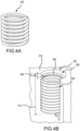
- a helical coil 402 is illustrated.
- the mounting hole 222 for mounting the brake actuator 300 to the brake housing includes pre-drilled threads 404.
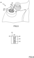
- the helical coil 402 in order that pre-drilled threads 404 of mounting hole 222 in brake actuator 300 exhibit increased thread strength and retention force, the helical coil 402, as illustrated in FIG. 4A , is inserted into pre-drilled threads 404 of the mounting hole 222, as seen in FIGs. 4B and 5 . As is illustrated in FIG.
- the helical coil 402 is typically installed one thread revolution or pitch 408, i.e., a distance from the crest of one thread to the crest of another thread measured along the length of the thread, below the surface 410 of the mounting hole 222.
- a portion of the helical coil 402 may break off during extraction of brake actuator 300, such that the remaining contact end 406 of the helical coil 402 is more than one thread revolution or pitch 408 below the surface 410 of the mounting hole 222.
- the helical coil 402 may be of a length that is shorter than a length 412 of the pre-drilled threads 404 and, therefore, the helical coil 402 may traverse further into the mounting hole 222 than intended, resulting in a deeply embedded helical coil 402, i.e., at least three to five thread pitches below the surface 410 of the mounting hole 222. For example, referring to FIG.
- the contact end 406 of the helical coil 402 is approximately three to five thread pitches 502 below the surface of the mounting hole 222.
- a blade 602 of a helical coil extraction device such as helical coil extraction device 700 shown in FIG. 7 , for engaging and extracting deeply embedded helical coils 402 is illustrated.
- the blade 602 of the helical coil extraction device is designed with an angle 604, which allows a portion of the blade 602, for engaging with a helical coil 402 that is installed one thread revolution or pitch 408 below the surface 410 of the mounting hole 222, to traverse further into the mounting hole 222 of the brake actuator 300 free of contact with a side of the mounting hole 222 of the brake actuator 300 and allows the blade 602 to bite into the deeply embedded helical coil 402 so that the helical coil 402 may be removed from the mounting hole 222 by rotation of the blade 602 and the helical coil 402.
- the helical coil extraction device 700 for engaging deeply embedded helical coils is illustrated.
- the helical coil extraction device 700 includes a shaft 702, a handle 704, and a blade 706.
- shaft 702 has a proximal end 708 and a distal end 710.
- the handle 704 is coupled to the proximal end 708 of the shaft 702.
- the blade 706 is coupled to the distal end 710 of the shaft 702.
- the blade 706 has a proximal end 712 and a distal end 714.
- the distal end 710 of the shaft 702 may include a slot 716 into which proximal end 712 the blade 706 may be inserted.
- the distal end 710 of the shaft 702 may include a set of holes 718 through which a set of rivets 720 may be inserted. The set of rivets traverse through the set of holes 718 and corresponding holes in a proximal end 712 of blade 706, securing the blade 706 to the shaft 702.
- the blade 706 has a first portion 802 and a second portion 804.
- the first portion 802 is substantially rectangular in shape.
- the second portion 804 tapers from first width at a first end 806 to a second width at a second end 808, where the second width is smaller than the first width.
- the blade 706 further includes a set of holes 810 that correspond to the set of holes 718 in the shaft 702 of FIG. 7 , through which the set of rivets 720 may traverse, securing the blade 706 to the shaft 702.
- the blade 706 has an overall length 902 that has an approximate diameter-to-length ratio of 5:24, with reference to the diameter of the helical coil, such as helical coil 402 of FIG. 4 , and the overall length 902 of the blade 706. In that regard, if the helical coil has a 5/16-inch (0.8 cm) nominal diameter, the overall length 902 of the blade 706 is approximately 1.5 inches (3.81 cm).
- the overall length 902 may be between 1.45 inches and 1.55 inches (3.68 cm and 3.94 cm) or between 1.475 inches and 1.525 inches (3.75 and 3.87 cm) if the helical coil has a 5/16-inch (0.8 cm) nominal diameter.
- the blade 706 has an overall width 904 that has an approximate diameter-to-width ratio of 1:1, with reference to the diameter of the helical coil, such as helical coil 402 of FIG. 4 , and the overall width 904 of the blade 706. In that regard, if the helical coil has a 5/16-inch (0.8 cm) nominal diameter, the overall width 904 is approximately 0.312 inches (0.79 cm).
- the overall width 904 may be between 0.302 inches and 0.322 inches (0.77 and 0.82 cm) or between 0.307 inches and 0.317 inches (0.78 and 0.81 cm) if the helical coil has a 5/16-inch (0.8 cm) nominal diameter.
- the first portion 802 of the blade 706 has a length 906 that has an approximate diameter-to-length ratio of 5:12, with reference to the diameter of the helical coil, such as helical coil 402 of FIG. 4 , and the length 906 of the first portion 802 of the blade 706.
- the length 906 is approximately 0.75 inches (1.9 cm).
- the length 906 may be between 0.7 inches and 0.8 inches (1.78 and 2.03 cm) or between 0.725 inches and 0.775 inches (1.84 and 1.97 cm) if the helical coil has a 5/16-inch (0.8 cm) nominal diameter.
- the second portion 804 of the blade 706 has a length 908 that also has an approximate diameter-to-length ratio of 5:12, with reference to the diameter of the helical coil, such as helical coil 402 of FIG. 4 , and the length 908 of the second portion 804 of the blade 706.
- the length 908 is approximately 0.75 inches (1.9 cm).
- the length 908 may be between 0.7 inches and 0.8 inches (1.78 and 2.03 cm) or between 0.725 inches and 0.775 (1.84 and 1.97 cm) inches if the helical coil has a 5/16-inch (0.8 cm) nominal diameter.
- the blade 706 has an overall thickness 910 that has an approximate thickness-to-diameter ratio of 1:5, with reference to the thickness 910 of the blade 706 and the diameter of the helical coil, such as helical coil 402 of FIG. 4 .
- the overall thickness 910 is approximately 0.062 inches (0.16 cm).
- the overall thickness 910 may be between 0.058 inches and 0.066 inches ( 0.15 and 0.17 cm) or between 0.060 inches and 0.064 inches (0.15 and 0.16 cm) if the helical coil has a 5/16-inch (0.8 cm) nominal diameter.
- the second portion tapers from the overall width 904 to a second width 912.
- the second width 912 that has an approximate width-to-diameter ratio of 4:5, with reference to the second width 902 of the blade 706 and the diameter of the helical coil, such as helical coil 402 of FIG. 4 .
- the second width 912 is approximately 0.250 inches (0.635cm).
- the second width 912 may be between 0.230 inches and 0.270 inches (0.58 and 0.68 cm) or between 0.240 inches and 0.260 inches (0.61 to 0.66 cm) if the helical coil has a 5/16-inch (0.8 cm) nominal diameter.
- the blade 706 tapers from the overall width of 904 to the second width 912 at an angle 704 of between 12 and 18 degrees. In various embodiment, the blade 706 tapers from the overall width of 904 to the second width 912 at an angle 704 of between 14 and 16 degrees. In various embodiment, the blade 706 tapers from the overall width of 904 to the second width 912 at an angle 704 of 15 degrees.
- the blade 706 includes beveled edges 918 that are also angled at angle 704 starting from the first end 920 of the second portion 804 to the second end 922 of the second portion 804 of the blade 706.
- the beveled edge 918 that is also angled at angle 704 causes the bevel 918 to start on a first side of the blade but only contacts the second side of the blade at a first end 924 of a length 914 continuing to the second end 922 of the second portion 804 of the blade 706.
- the length 914 has an approximate width-to-height ratio of 5:8, with reference to the diameter of the helical coil, such as helical coil 402 of FIG. 4 , and the length 914 of the blade 706.
- the length 914 is approximately 0.5 inches (1.27 cm).
- the length 914 may be between 0.46 inches and 0.54 inches (1.17 and 1.37 cm) or between 0.48 inches and 0.52 inches (1.22 and 1.32 cm) if the helical coil has a 5/16-inch (0.8 cm) nominal diameter.
- the direction of the bevel edges 918 depends on the whether the pre-drilled threads, such as the pre-drilled threads 404 of FIG. 4B , are right-handed threads or left-handed threads.
- the bevel of the bevel edges 918 may be in a first direction if the pre-drilled threads are right-handed threads and the bevel of the bevel edges 918 may be in a second direction opposite the first direction if the pre-drilled threads are left-handed threads.
- an angled width 916 at the second end 922 of the blade 706 from edge 926 to edge 928 on either side of the blade 706 has an approximate width-to-diameter ratio of 1:1.4, with reference to the angled width 916 at the second end 922 of the blade 706 and the diameter of the helical coil, such as helical coil 402 of FIG. 4 .
- the angled width 916 is approximately 0.225 inches (0.57 cm).
- the angled width 916 may be between 0.215 inches and 0.235 inches (0.55 and 0.6 cm) or between 0.22 inches and 0.23 inches (0.56 and 0.58 cm) if the helical coil has a 5/16-inch (0.8 cm) nominal diameter.
- an angle 930 of the beveled edge 918 is between 11 degrees and 19 degrees with respect the second width 912 of the blade 706.
- the angle 930 of the bevel edge 918 is between 13 degrees and 13 degrees with respect the second width 912 of the blade 706.
- the angle 930 of the beveled edge 918 is 15 degrees with respect the second width 912 of the blade 706.
- the blade 706 may be hardened to improve an ability of the blade 706 to withstand the forces associated with removal of the helical coil 402.
- the blade 706 may be protected from oxygen by wrapping the blade 706 in a heat treatment foil.
- the blade 706 may then be heat treated at a temperature of between 1700 degrees Fahrenheit (°F) and 1800 °F (927 and 982 °C).
- the blade 706 may be heat treated at a temperature of between 1725 °F and 1775 °F (940 and 968 °C).
- the blade 706 may be heat treated at a temperature 1750 °F (954°C).
- the blade may undergo a first air quenching at a temperature of between 50 °F and 100 °F (10 and 38 °C). In various embodiments, the blade may undergo the first air quenching at a temperature of between 60 °F and 90 °F (15.5 and 32°C). In various embodiments, the blade may undergo the first air quenching at a temperature of between 70 °F and 80 °F (21 and 27 °C). After the first air quenching, in various embodiments, the blade 706 may undergo a first tempering at a temperature of between 800 °F and 1000 °F (427 and 538 °C).
- the blade 706 may undergo the first tempering at a temperature of between 850 °F and 950 °F (454 and 510 °C). In various embodiments, the blade 706 may undergo the first tempering at a temperature of 900 °F (482°C).
- the blade may undergo a second air quenching at a temperature of between 50 °F and 100 °F (10 and 38 °C). In various embodiments, the blade may undergo the second air quenching at a temperature of between 60 °F and 90 °F (15.5 and 32°C). In various embodiments, the blade may undergo the second air quenching at a temperature of between 70 °F and 80 °F (21 and 27 °C). After the second air quenching, in various embodiments, the blade 706 may undergo a second tempering at a temperature of between 800 °F and 1000 °F (427 and 538 °C).
- the blade 706 may undergo the second tempering at a temperature of between 850 °F and 950 °F (454 and 510 °C).. In various embodiments, the blade 706 may undergo the second tempering at a temperature of 900 °F (482°C). After the second tempering, in various embodiments, the blade may undergo a third and final air quenching at a temperature of between 50 °F and 100 °F (10 and 38 °C). In various embodiments, the blade may undergo the third and final air quenching at a temperature of between 60 °F and 90 °F (15.5 and 32°C). In various embodiments, the blade may undergo the third and final air quenching at a temperature of between 70 °F and 80 °F (21 and 27 °C).
- the heat treatment, the first tempering and the second tempering may be performed for between 45 and 90 minutes. In various embodiments, the heat treatment, the first tempering and the second tempering may be performed for between 55 and 80 minutes. In various embodiments, the heat treatment, the first tempering and the second tempering may be performed for between 65 and 70 minutes.
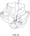
- a blade of a helical coil extraction device engaging with a deeply embedded helical coil is illustrated.
- the blade 706 is coupled to the shaft 702 of the helical coil extraction device 700.
- the distal end of the shaft 702 may be tapped with another object, for example, pliers, a hammer, or the like.
- the helical coil 402 may then be extracted by rotating the shaft 702 to which the blade 706 is coupled via a handle or a drill, among others, in a clockwise or counterclockwise direction depending on whether the threads are right-handed threads or left-handed threads.
- the direction of the bevel edges of the blade 706 depends on the whether the pre-drilled threads, such as the pre-drilled threads 404 of FIG. 4B , are right-handed threads or left-handed threads.
- the bevel of the bevel edges of the blade 706 may be in a first direction if the pre-drilled threads are right-handed threads and the bevel of the bevel edges of the blade 706 may be in a second direction opposite the first direction if the pre-drilled threads are left-handed threads.
- references to "one embodiment,” “an embodiment,” “various embodiments,” etc. indicate that the embodiment described may include a particular feature, structure, or characteristic, but every embodiment may not necessarily include the particular feature, structure, or characteristic. Moreover, such phrases are not necessarily referring to the same embodiment. Further, when a particular feature, structure, or characteristic is described in connection with an embodiment, it is submitted that it is within the knowledge of one skilled in the art to affect such feature, structure, or characteristic in connection with other embodiments whether or not explicitly described. After reading the description, it will be apparent to one skilled in the relevant art(s) how to implement the disclosure in alternative embodiments.
- Numbers, percentages, or other values stated herein are intended to include that value, and also other values that are about or approximately equal to the stated value, as would be appreciated by one of ordinary skill in the art encompassed by various embodiments of the present disclosure.
- a stated value should therefore be interpreted broadly enough to encompass values that are at least close enough to the stated value to perform a desired function or achieve a desired result.
- the stated values include at least the variation to be expected in a suitable industrial process, and may include values that are within 10%, within 5%, within 1%, within 0.1%, or within 0.01% of a stated value.
- the terms “substantially,” “about,” or “approximately” as used herein represent an amount close to the stated amount that still performs a desired function or achieves a desired result.
- the term “substantially,” “about,” or “approximately” may refer to an amount that is within 10% of, within 5% of, within 1% of, within 0.1% of, and within 0.01% of a stated amount or value
Landscapes
- Engineering & Computer Science (AREA)
- Mechanical Engineering (AREA)
- Heat Treatment Of Articles (AREA)
Applications Claiming Priority (1)
| Application Number | Priority Date | Filing Date | Title |
|---|---|---|---|
| US17/900,628 US11872677B1 (en) | 2022-08-31 | 2022-08-31 | Deeply embedded helical coil extraction device |
Publications (2)
| Publication Number | Publication Date |
|---|---|
| EP4335592A1 true EP4335592A1 (de) | 2024-03-13 |
| EP4335592B1 EP4335592B1 (de) | 2025-12-24 |
Family
ID=87863158
Family Applications (1)
| Application Number | Title | Priority Date | Filing Date |
|---|---|---|---|
| EP23194069.3A Active EP4335592B1 (de) | 2022-08-31 | 2023-08-29 | Tief eingebettete spiralspulenextraktionsvorrichtung |
Country Status (2)
| Country | Link |
|---|---|
| US (2) | US11872677B1 (de) |
| EP (1) | EP4335592B1 (de) |
Families Citing this family (1)
| Publication number | Priority date | Publication date | Assignee | Title |
|---|---|---|---|---|
| US11872677B1 (en) * | 2022-08-31 | 2024-01-16 | Goodrich Corporation | Deeply embedded helical coil extraction device |
Citations (3)
| Publication number | Priority date | Publication date | Assignee | Title |
|---|---|---|---|---|
| BE470214A (de) * | 1939-01-24 | 1947-01-31 | ||
| GB842345A (en) * | 1959-03-13 | 1960-07-27 | Cross Mfg Co 1938 Ltd | Method and tool for screwing coiled wire inserts into tapped holes |
| US4716797A (en) * | 1986-08-20 | 1988-01-05 | Colvin David S | Screwdriver with concave blade |
Family Cites Families (18)
| Publication number | Priority date | Publication date | Assignee | Title |
|---|---|---|---|---|
| US178627A (en) * | 1876-06-13 | Improvement in farriers buttresses | ||
| US2244824A (en) | 1939-01-24 | 1941-06-10 | Aireraft Screw Products Compan | Extracting tool |
| US2513792A (en) | 1946-11-13 | 1950-07-04 | Heli Coil Corp | Tool for inserting and extracting wire coil inserts in and from tapped holes |
| US5507083A (en) * | 1992-08-31 | 1996-04-16 | Eaton Corporation | Stretching brake shoe return springs |
| US5455996A (en) * | 1992-12-28 | 1995-10-10 | Lisle Corporation | Brake spring tool |
| US6108882A (en) * | 1997-12-22 | 2000-08-29 | Hodgson; Dave | Brake spring tool |
| US6574845B2 (en) * | 2001-10-01 | 2003-06-10 | Hsin Fa Kang | Pincers for assembling and disassembling the spring of the brake shoes in a drum brake |
| DE10305467B4 (de) | 2003-02-13 | 2012-10-31 | Alstom Technology Ltd. | Ausbauwerkzeug zum Extrahieren von spiralförmigen Gewindeeinsätzen sowie Anwendung des Ausbauwerkzeugs |
| US6886229B1 (en) * | 2003-11-20 | 2005-05-03 | Sean F. Wilson | Hinge pin remover tool |
| US7322084B2 (en) * | 2005-05-26 | 2008-01-29 | Marc Wayne Horsman | Spring extension tool |
| US20070062046A1 (en) * | 2005-09-21 | 2007-03-22 | Hsu Shin J | Chisel having replaceable tip |
| US7337515B2 (en) * | 2006-01-25 | 2008-03-04 | Breaching Technologies, Inc. | Hybrid breaching bar |
| USD627617S1 (en) * | 2010-05-26 | 2010-11-23 | Vaughan & Bushnell Manufacturing Company | Combination hand tool bar |
| US8826544B1 (en) * | 2011-02-14 | 2014-09-09 | John David Savage, Jr. | Sealant removal tool |
| US9242358B2 (en) * | 2012-02-09 | 2016-01-26 | Honda Motor Co., Ltd. | Looped pin installation apparatus |
| US8495777B1 (en) * | 2012-02-15 | 2013-07-30 | Scott E. Dixon | Rescue punch for diver knife |
| US9402337B2 (en) * | 2014-04-07 | 2016-08-02 | Nicholas S Al-Taweel | Shovel with a fulcrum projection and a method for its use |
| US11872677B1 (en) * | 2022-08-31 | 2024-01-16 | Goodrich Corporation | Deeply embedded helical coil extraction device |
-
2022
- 2022-08-31 US US17/900,628 patent/US11872677B1/en active Active
-
2023
- 2023-08-29 EP EP23194069.3A patent/EP4335592B1/de active Active
- 2023-12-12 US US18/536,643 patent/US12290904B2/en active Active
Patent Citations (3)
| Publication number | Priority date | Publication date | Assignee | Title |
|---|---|---|---|---|
| BE470214A (de) * | 1939-01-24 | 1947-01-31 | ||
| GB842345A (en) * | 1959-03-13 | 1960-07-27 | Cross Mfg Co 1938 Ltd | Method and tool for screwing coiled wire inserts into tapped holes |
| US4716797A (en) * | 1986-08-20 | 1988-01-05 | Colvin David S | Screwdriver with concave blade |
Also Published As
| Publication number | Publication date |
|---|---|
| US11872677B1 (en) | 2024-01-16 |
| EP4335592B1 (de) | 2025-12-24 |
| US12290904B2 (en) | 2025-05-06 |
| US20240123588A1 (en) | 2024-04-18 |
Similar Documents
| Publication | Publication Date | Title |
|---|---|---|
| US12290904B2 (en) | Deeply embedded helical coil extraction device | |
| US2830635A (en) | Self-locking set screw having frangible intermediate portion | |
| US8888430B2 (en) | Antitheft locking device | |
| EP2846052A1 (de) | Drehmomentsteuerungs-Brechschraube | |
| DE60316858T2 (de) | Vorrichtung zur Befestigung für ein Lüfterrad | |
| EP3032093B1 (de) | Befestigungsvorrichtung zur befestigung eines rotorblattes an einer rotornabe einer windkraftanlage | |
| DE102017008782A1 (de) | System und Verfahren zur Überwachung einer Flanschverbindung einer Windenergieanlage | |
| US20170297181A1 (en) | Key device for holding a nut retainer | |
| EP2469106B1 (de) | Diebstahlsicherungsvorrichtung | |
| US3378906A (en) | Wire wrapping tool | |
| US4724612A (en) | Method for winding wires to make a harness | |
| US20160375566A1 (en) | Tightening tool for coaxial connectors | |
| US5682801A (en) | Jam proof lug nut | |
| EP2924303A1 (de) | Erdungsmutter | |
| EP3053758A2 (de) | Zugbolzenrückhaltesystem für radanordnung | |
| EP2498338B1 (de) | Anordnung mit einer als Rohrstück ausgeführten Klemme aus Metall und mindestens einer Klemmschraube | |
| EP3305657B1 (de) | Elektrische verstellpropeller-anordnung | |
| WO2013010648A1 (de) | Kabelanschlussbauteil | |
| US20210048057A1 (en) | Coating film peeling nut | |
| US4174558A (en) | Fan or wheel pulling device | |
| WO2015153416A1 (en) | Edge protection bushing with integrated clamp | |
| EP3618593A1 (de) | Verfahren zum beabstandeten verbinden von leiterplatten sowie montageeinheit und montagebaugruppe | |
| EP1378671B1 (de) | Klemmschraube mit Klemmscheibe und zugehörige Klemmvorrichtung | |
| US10773365B2 (en) | Installation tool for a wire thread insert having an installation pin that can be bent back, and installation method | |
| US2446174A (en) | Insert |
Legal Events
| Date | Code | Title | Description |
|---|---|---|---|
| PUAI | Public reference made under article 153(3) epc to a published international application that has entered the european phase |
Free format text: ORIGINAL CODE: 0009012 |
|
| STAA | Information on the status of an ep patent application or granted ep patent |
Free format text: STATUS: THE APPLICATION HAS BEEN PUBLISHED |
|
| AK | Designated contracting states |
Kind code of ref document: A1 Designated state(s): AL AT BE BG CH CY CZ DE DK EE ES FI FR GB GR HR HU IE IS IT LI LT LU LV MC ME MK MT NL NO PL PT RO RS SE SI SK SM TR |
|
| STAA | Information on the status of an ep patent application or granted ep patent |
Free format text: STATUS: REQUEST FOR EXAMINATION WAS MADE |
|
| 17P | Request for examination filed |
Effective date: 20240912 |
|
| RBV | Designated contracting states (corrected) |
Designated state(s): AL AT BE BG CH CY CZ DE DK EE ES FI FR GB GR HR HU IE IS IT LI LT LU LV MC ME MK MT NL NO PL PT RO RS SE SI SK SM TR |
|
| GRAP | Despatch of communication of intention to grant a patent |
Free format text: ORIGINAL CODE: EPIDOSNIGR1 |
|
| STAA | Information on the status of an ep patent application or granted ep patent |
Free format text: STATUS: GRANT OF PATENT IS INTENDED |
|
| INTG | Intention to grant announced |
Effective date: 20250725 |
|
| GRAS | Grant fee paid |
Free format text: ORIGINAL CODE: EPIDOSNIGR3 |
|
| GRAA | (expected) grant |
Free format text: ORIGINAL CODE: 0009210 |
|
| STAA | Information on the status of an ep patent application or granted ep patent |
Free format text: STATUS: THE PATENT HAS BEEN GRANTED |
|
| AK | Designated contracting states |
Kind code of ref document: B1 Designated state(s): AL AT BE BG CH CY CZ DE DK EE ES FI FR GB GR HR HU IE IS IT LI LT LU LV MC ME MK MT NL NO PL PT RO RS SE SI SK SM TR |
|
| REG | Reference to a national code |
Ref country code: CH Ref legal event code: F10 Free format text: ST27 STATUS EVENT CODE: U-0-0-F10-F00 (AS PROVIDED BY THE NATIONAL OFFICE) Effective date: 20251224 Ref country code: GB Ref legal event code: FG4D |
|
| REG | Reference to a national code |
Ref country code: DE Ref legal event code: R096 Ref document number: 602023010032 Country of ref document: DE |
|
| REG | Reference to a national code |
Ref country code: LT Ref legal event code: MG9D |
|
| PG25 | Lapsed in a contracting state [announced via postgrant information from national office to epo] |
Ref country code: NO Free format text: LAPSE BECAUSE OF FAILURE TO SUBMIT A TRANSLATION OF THE DESCRIPTION OR TO PAY THE FEE WITHIN THE PRESCRIBED TIME-LIMIT Effective date: 20260324 |
|
| PG25 | Lapsed in a contracting state [announced via postgrant information from national office to epo] |
Ref country code: FI Free format text: LAPSE BECAUSE OF FAILURE TO SUBMIT A TRANSLATION OF THE DESCRIPTION OR TO PAY THE FEE WITHIN THE PRESCRIBED TIME-LIMIT Effective date: 20251224 Ref country code: HR Free format text: LAPSE BECAUSE OF FAILURE TO SUBMIT A TRANSLATION OF THE DESCRIPTION OR TO PAY THE FEE WITHIN THE PRESCRIBED TIME-LIMIT Effective date: 20251224 |
|
| PG25 | Lapsed in a contracting state [announced via postgrant information from national office to epo] |
Ref country code: RS Free format text: LAPSE BECAUSE OF FAILURE TO SUBMIT A TRANSLATION OF THE DESCRIPTION OR TO PAY THE FEE WITHIN THE PRESCRIBED TIME-LIMIT Effective date: 20260324 |
|
| PG25 | Lapsed in a contracting state [announced via postgrant information from national office to epo] |
Ref country code: LV Free format text: LAPSE BECAUSE OF FAILURE TO SUBMIT A TRANSLATION OF THE DESCRIPTION OR TO PAY THE FEE WITHIN THE PRESCRIBED TIME-LIMIT Effective date: 20251224 |