EP4335718B1 - Coque, en particulier paroi latérale et/ou porte de véhicule, destinée à recevoir une vitre pour un véhicule, en particulier un véhicule ferroviaire, procédé de fabrication de la coque et véhicule comprenant la coque - Google Patents
Coque, en particulier paroi latérale et/ou porte de véhicule, destinée à recevoir une vitre pour un véhicule, en particulier un véhicule ferroviaire, procédé de fabrication de la coque et véhicule comprenant la coque Download PDFInfo
- Publication number
- EP4335718B1 EP4335718B1 EP23191651.1A EP23191651A EP4335718B1 EP 4335718 B1 EP4335718 B1 EP 4335718B1 EP 23191651 A EP23191651 A EP 23191651A EP 4335718 B1 EP4335718 B1 EP 4335718B1
- Authority
- EP
- European Patent Office
- Prior art keywords
- opening
- bodyshell
- edge
- vehicle
- mounting
- Prior art date
- Legal status (The legal status is an assumption and is not a legal conclusion. Google has not performed a legal analysis and makes no representation as to the accuracy of the status listed.)
- Active
Links
Images
Classifications
-
- B—PERFORMING OPERATIONS; TRANSPORTING
- B61—RAILWAYS
- B61D—BODY DETAILS OR KINDS OF RAILWAY VEHICLES
- B61D25/00—Window arrangements peculiar to rail vehicles
Definitions
- the invention relates to a bodyshell, in particular a side wall and/or a vehicle door, for receiving a window for a vehicle, in particular a rail vehicle according to the preamble of claim 1, a method for producing the bodyshell according to claim 7 and a vehicle comprising the bodyshell according to claim 15.
- the object underlying the invention is therefore to provide a solution that overcomes the disadvantages of the prior art, in particular the technical problem is to provide a solution that ensures optimized properties of bodyshells in vehicles, preferably in rail vehicles.
- the shell in particular a side wall and/or a vehicle door, for receiving a window for a vehicle according to the preamble of claim 1 by its characterizing features
- the method for producing the shell, in particular a side wall and/or a vehicle door for receiving a window for a vehicle, in particular a rail vehicle, and the vehicle according to the generic term of claim 15, by its features.
- the shell according to the invention in particular a side wall and/or a vehicle door of a vehicle, in particular a rail vehicle, having at least one opening for the insertion of a window pane by means of a rubber clamping frame, wherein the opening has a plurality, in particular three or four, curved corners and the opening edge is designed for the installation of at least one clamping rubber, the opening edge is designed such that at least in the corners a reinforcement of the opening edge is formed such that in the corners a thickening of the opening edge of the shell towards at least one of the outer sides, in particular having a value from a value range between 2 to 6 mm, is formed by a non-detachable connection between the shell and a reinforcing device which is introduced in each corner, in particular at least congruent with the curved region.
- the shell according to the invention thus provides reinforced corners for a (door) window lower chord assembly that are stable, have the necessary strength, and also take into account the dimensioning properties that are given for (door) windows.
- the invention also provides a reinforcement that essentially runs around the corners. so that the straight sidewall sections remain free of reinforcement. This measure prevents the risk of crevice corrosion, which can occur with typical reinforcement of metal frames by adding additional sheets. Furthermore, it can reduce both the number and cost of additional sheets required.
- a value range of 2 to 6 mm appears to be a suitable range for common use.
- the invention is not limited to this; rather, other value range pairs may appear more suitable, for example, due to technical advances, other parameters or requirements for the bodyshell, and/or other changed framework conditions, as long as they ensure, in particular, that the rubber clamp is pulled up and that the rubber clamp provides an optimal clamping effect. They are therefore also encompassed by the invention within the scope of protection defined by the claims.
- the size of the stated value range limits can also vary by the stated values, in particular by fractions of a millimeter.
- the opening edge is formed in such a way that at least in the corners a reinforcement of the opening edge is applied in such a way that in the corners a thickening of the opening edge of the shell towards at least one of the outer sides is formed by a non-detachable connection between the shell and a reinforcing device which is introduced in each corner, in particular at least congruent with the curved region.
- the method according to the invention is characterized in that it provides the shell according to the invention as a result and thus contributes to the realization of the aforementioned advantages.
- the vehicle according to the invention in particular a rail vehicle, is characterized in that it comprises a bodyshell according to the invention and/or one or more of the developments of the bodyshell.
- the shell, at least in the region of the opening edge, and the reinforcement device are made of identical material, in particular of metal.
- This design also generally simplifies the selection of the most suitable type of permanent connection, for example, because both elements react physically in the same way. Choosing metal as the material takes advantage of its excellent processing properties, strength, and stability.
- the non-detachable connection is designed as a, in particular welded joint produced by laser welding.
- Laser welding is a further improvement in terms of these properties and also features extremely fine weld seams, which is beneficial for further processing and the installation of the clamping rubbers, but also offers less surface area for corrosion and thus also supports the optimization according to the invention in this regard.
- the shell according to the invention can alternatively or additionally also be designed in such a way that the non-detachable connection is designed as an adhesive bond or by integrally forming the opening frame.
- a bonding process can be the method of choice to create a permanent connection, especially when different materials are involved, while a one-piece molding process is used when the same materials are used and can be used advantageously, as it essentially saves an extra step for the connection as well as materials and energy that would otherwise be required for this purpose. would be necessary because a one-piece molding inherently results in a non-detachable connection. All manufacturing processes that result in a one-piece product are conceivable, provided the product supports the stability, strength, and dimensioning advantages of the invention.
- the shell according to the invention can be further developed in such a way that the reinforcing device is introduced in such a way that it tapers in the two directions leading away from the apex of the curvature in such a way that the thickness corresponds to the thickness of the straight sections of the opening frame, in particular is 1.8 mm, wherein the tapered end, in particular near the beginning of the curvature, is placed in such a way that the installation of a clamping rubber on the opening edge, in particular carried out by manual pulling, is optimized with regard to the effort required for installation and the maximum holding force at the end point of installation.
- a lubricant such as a grease fitting, can be used to improve installation.
- the method according to the invention can be further developed in such a way that the shell, at least in the region of the opening edge, and the reinforcement device are formed from identical material, in particular from metal.
- the non-detachable connection is designed as a welded connection, in particular produced by laser welding.
- the method according to the invention can further be developed alternatively or additionally in such a way that the shell, at least in the region of the opening edge, and the reinforcement device are formed from different materials.
- reinforcement made of a different material may, for example, be necessary or advantageous if this can increase the stability, strength and/or dimensioning advantages to such an extent that any disadvantages resulting from moving away from identical materials can be accepted.
- the non-detachable connection can be designed as an adhesive bond or by integrally forming the opening frame.
- Bonding will be particularly advantageous in manufacturing based on different materials, while one-piece molding can lead to savings in manufacturing steps.
- the method can be developed in such a way that the reinforcement device is introduced in such a way that it extends into the two Directions tapered in such a way that the thickness corresponds to the thickness of the straight sections of the opening frame, in particular is 1.8 mm, wherein the tapered end, in particular near the beginning of the curvature, is placed in such a way that an assembly of a clamping rubber on the opening edge, in particular carried out by manual pulling, is optimized with regard to the effort required for assembly and maximum holding force at the assembly end point.
- the step of applying the clamping rubber is simplified, as the ramping can bridge differences in the thickness of the opening frame compared to the reinforced corners.
- the thicknesses mentioned here, 1.8 mm and 3-4 mm correspond to common boundary values for an opening frame and promising values for reinforcement that ensures sufficient stability.
- other values and value pairs can be used. These can be determined, for example, by the type of manufacturing, the materials used, field experience, and/or optimization methods, such as simulation.
- the method according to the invention can further be advantageously developed in such a way that the reinforcement is formed by at least one curved edged sheet.
- the curvature of the edged sheet is produced by rolling, wherein in such a case the edged sheet is only laser welded after rolling.
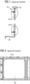
- FIG. 1 A sectional drawing shows how a pane of GLASS is fixed in a shell RB according to the state of the art by means of a clamping rubber KG.
- the shell RB from Figure 1 is provided with a reinforcement as an overlap RB_V in such a way that it runs around the entire opening ⁇ N of the shell RB according to the state of the art.
- the shell according to the invention in particular a side wall and/or a vehicle door, for receiving a window for a vehicle, in particular a rail vehicle, a method for producing the shell and a vehicle comprising the shell are used.
- a method for producing the shell and a vehicle comprising the shell are used.
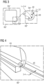
- an embodiment is also shown schematically.
- an opening ⁇ N* resulting from the invention which differs from the opening known from the prior art in that it is enclosed by a shell RB* according to the invention, which, in contrast to the shell RB known from the prior art, does not have a completely circumferential reinforcement of the edge of the opening ⁇ N* according to the invention, but has reinforcements in the corners.
- a curved part for example a curved edged sheet or flat part with ramps KB, is inserted in the corner and is non-detachably connected to the straight parts of the edge of the opening ⁇ N* according to the invention.
- this non-detachable connection is - as a method step of an embodiment of the method according to the invention - a laser weld, which - as a method step according to the embodiment of the method - is carried out after rolling the edged sheet KB.
- this edged sheet or flat part with ramps KB has a ramp AR on both sides of the curvature, which begins with the thickness of the straight parts of the edge of the opening ⁇ N* according to the invention, in the illustrated embodiment 1.8 cm, and extends towards the apex of the curvature of the edged sheet KB up to the reinforcement thickness in the curved area of the edged sheet KB, in the example shown in a range of 3 to 4 cm, ramps up so that a clamping rubber KG can be easily pulled on.
- the start and end points of the ramp may be chosen differently, for example due to (failed) attempts and/or (other) optimization procedures.
- the embodiment shown creates a "tailored blank" side wall by welding thicker sheets into the corners subject to higher loads using laser welding.
- the thickness tapers from a value of between 3 and 4 cm at the end of the curvature in the direction away from the apex of the curvature of the edged sheet KB to a thickness of 1.8 cm.
- edge plates KB according to the embodiment of the invention are designed in such a way that they compensate for the differences in thickness via a ramp in such a way that, on the one hand, the functionality of the rubber clamping frame is guaranteed and, on the other hand, the strength and stability requirements in the area of high loads are taken into account.
- the edged sheet can be produced, for example, by milling an original sheet of the same thickness all around, the ramp and create the normal-thickness area by removing material.
- the reinforcement device would therefore be the remaining material that makes the areas thicker than the rest.
Landscapes
- Engineering & Computer Science (AREA)
- Mechanical Engineering (AREA)
- Seal Device For Vehicle (AREA)
Claims (15)
- Coque (RB), en particulier une paroi latérale et/ou une porte de véhicule, en particulier d'un véhicule ferroviaire, présentant au moins une ouverture (ÖN) pour l'utilisation d'une vitre de fenêtre au moyen d'un cadre de serrage en caoutchouc, dans laquelle l'ouverture présente une pluralité, en particulier trois ou quatre, coins courbés et le rebord d'ouverture est conçu pour le montage d'au moins un caoutchouc de serrage (KG), caractérisé en ce que le rebord d'ouverture est conçu de telle sorte qu'au moins dans les coins respectivement un renforcement du rebord d'ouverture est formé de telle sorte que dans les coins un épaississement (AR) du rebord d'ouverture de la coque qui présente en particulier une valeur à partir d'une plage de valeurs entre 2 et 6 mm par rapport à au moins une des faces externes est formé par le biais d'au moins un raccord non détachable entre la coque et un dispositif de renforcement qui est introduit dans chaque coin en particulier au moins de manière coïncidente avec la zone courbée.
- Coque selon la revendication précédente, caractérisée en ce que la coque, au moins dans la zone du rebord d'ouverture, et le dispositif de renforcement sont réalisés à partir d'un matériau identique, en particulier à partir d'un métal.
- Coque selon la revendication précédente, caractérisée en ce que le raccord non détachable est conçu en tant que raccord à souder, généré en particulier par soudage au laser.
- Coque selon la revendication 1, caractérisée en ce que la coque, au moins dans la zone du rebord d'ouverture, et le dispositif de renforcement sont réalisés à partir d'un matériau différent.
- Coque selon l'un des revendications précédentes, caractérisé en ce que la liaison non détachable est conçue en tant que collage ou par le biais d'un façonnage d'un seul tenant, comme par exemple par fraisage d'une pièce, du cadre d'ouverture.
- Coque selon l'une quelconque des revendications précédentes, caractérisée en ce que le dispositif de renforcement est introduit de telle sorte qu'il se rétrécit dans les deux directions s'éloignant du sommet de courbure de telle sorte que la mesure de l'épaisseur concorde avec l'épaisseur avec les sections droites du cadre d'ouverture, représente en particulier 1,8 mm, dans laquelle l'extrémité de rétrécissement, en particulier près du début de courbure, est placée de telle sorte qu'un montage, pratiqué en particulier par le biais d'un remontage manuel, d'un caoutchouc de serrage sur le rebord d'ouverture en ce qui concerne un effort pour le montage et une force de retenue maximale au niveau du point d'extrémité de montage est optimisé.
- Procédé destiné à la fabrication d'une coque (RB), en particulier d'une paroi latérale et/ou d'une porte de véhicule, d'un véhicule en particulier ferroviaire, présentant au moins une ouverture (ÖN) pour l'insertion d'une vitre de fenêtre au moyen d'un cadre de serrage en caoutchouc, dans lequel l'ouverture présente une pluralité, en particulier trois ou quatre, de coins courbés et le rebord d'ouverture est conçu pour le montage d'au moins un caoutchouc de serrage (KG), caractérisé en ce que le rebord d'ouverture est formé de telle sorte qu'au moins dans les coins respectivement un renforcement du rebord d'ouverture est apposé de telle sorte que dans les coins un épaississement (AR) du rebord d'ouverture de la coque par rapport à au moins une des faces externes est formé par le biais d'au moins un raccord non détachable entre la coque et un dispositif de renforcement qui est introduit dans chaque coin en particulier au moins de manière coïncidente avec la zone courbée.
- Procédé selon la revendication précédente, caractérisé en ce que la coque, au moins dans la zone du rebord d'ouverture, et le dispositif de renforcement sont configurés à partir d'un matériau identique, en particulier à partir d'un métal.
- Procédé selon la revendication précédente, caractérisé en ce que le raccord non détachable est conçu en tant que raccord à souder, en particulier généré par soudage au laser.
- Procédé selon la revendication 7, caractérisé en ce que la coque, au moins dans la zone du rebord d'ouverture, et le dispositif de renforcement sont configurés à partir d'un matériau différent.
- Procédé selon l'une quelconque des revendications 7 à 10, caractérisé en ce que le raccord non détachable est conçu en tant que collage ou par le biais d'un façonnage d'un seul tenant, comme par exemple par fraisage de pièces, du cadre d'ouverture.
- Procédé selon l'une quelconque des revendications 7 à 11, caractérisé en ce que le dispositif de renforcement est introduit de telle sorte qu'il se rétrécit dans les deux directions s'éloignant du sommet de courbure de telle sorte que la mesure de l'épaisseur concorde avec l'épaisseur avec les sections droites du cadre d'ouverture, représente en particulier 1,8 mm, dans laquelle l'extrémité de rétrécissement, en particulier près du début de courbure, est placée de telle sorte qu'un montage pratiqué en particulier par le biais d'un hissage manuel d'un caoutchouc de serrage sur le rebord d'ouverture en ce qui concerne l'effort pour le montage et une force de retenue maximale au niveau du point d'extrémité de montage est optimisé.
- Procédé selon l'une quelconque des revendications 7 à 12, caractérisé en ce que le renforcement est formé par au moins une tôle pliée courbée.
- Procédé selon la revendication 13, caractérisé en ce que la courbure de la tôle pliée est générée par le biais d'un laminage, dans lequel la tôle pliée n'est soudée au laser qu'après le laminage.
- Véhicule, en particulier véhicule ferroviaire, comprenant une coque selon l'une quelconque des revendications 1 à 6.
Applications Claiming Priority (1)
| Application Number | Priority Date | Filing Date | Title |
|---|---|---|---|
| DE102022209047.0A DE102022209047A1 (de) | 2022-08-31 | 2022-08-31 | Rohbau, insbesondere eine Seitenwand und/oder eine Fahrzeugtür, zur Aufnahme einer Scheibe für ein Fahrzeug, insbesondere Schienenfahrzeug, Verfahren zur Herstellung des Rohbaus sowie den Rohbau umfassendes Fahrzeug |
Publications (3)
| Publication Number | Publication Date |
|---|---|
| EP4335718A1 EP4335718A1 (fr) | 2024-03-13 |
| EP4335718C0 EP4335718C0 (fr) | 2025-06-25 |
| EP4335718B1 true EP4335718B1 (fr) | 2025-06-25 |
Family
ID=87580227
Family Applications (1)
| Application Number | Title | Priority Date | Filing Date |
|---|---|---|---|
| EP23191651.1A Active EP4335718B1 (fr) | 2022-08-31 | 2023-08-16 | Coque, en particulier paroi latérale et/ou porte de véhicule, destinée à recevoir une vitre pour un véhicule, en particulier un véhicule ferroviaire, procédé de fabrication de la coque et véhicule comprenant la coque |
Country Status (2)
| Country | Link |
|---|---|
| EP (1) | EP4335718B1 (fr) |
| DE (1) | DE102022209047A1 (fr) |
Family Cites Families (5)
| Publication number | Priority date | Publication date | Assignee | Title |
|---|---|---|---|---|
| FR1222930A (fr) * | 1958-04-02 | 1960-06-14 | Budd Co | Paroi de caisse, en particulier pour voitures de chemin de fer |
| NL6404806A (fr) * | 1963-05-01 | 1964-11-02 | ||
| CN203211314U (zh) * | 2013-03-26 | 2013-09-25 | 常州天晟新材料股份有限公司 | 一种轨道交通车辆内饰用侧墙板 |
| CN204821573U (zh) * | 2015-08-17 | 2015-12-02 | 青岛康平铁路玻璃钢有限公司 | 一种列车车厢模压窗口墙板 |
| CN110466550B (zh) * | 2019-08-27 | 2020-11-24 | 中车青岛四方机车车辆股份有限公司 | 轨道车辆侧墙结构及轨道车辆 |
-
2022
- 2022-08-31 DE DE102022209047.0A patent/DE102022209047A1/de not_active Withdrawn
-
2023
- 2023-08-16 EP EP23191651.1A patent/EP4335718B1/fr active Active
Also Published As
| Publication number | Publication date |
|---|---|
| EP4335718A1 (fr) | 2024-03-13 |
| DE102022209047A1 (de) | 2024-02-29 |
| EP4335718C0 (fr) | 2025-06-25 |
Similar Documents
| Publication | Publication Date | Title |
|---|---|---|
| DE102011005977A1 (de) | Verstärkungsblech einer B-Säule | |
| EP3724436B1 (fr) | Élément de support pour une vitre latérale du véhicule pouvant être soulevée et abaissée | |
| WO2016078821A1 (fr) | Cadre d'un toit de véhicule et sa fabrication | |
| EP3484735B1 (fr) | Procédé de fabrication d'un toit de véhicule, toit modulaire pour toit de véhicule et toit de véhicule pour véhicule à moteur | |
| DE20313770U1 (de) | Innenverkleidungsteil | |
| DE102008021224B4 (de) | Schienenfahrzeug | |
| DE102015202080B4 (de) | Karosseriestruktur für ein Fahrzeug | |
| EP2559609B1 (fr) | Cadre de renfort et procédé de mise en place d'un cadre de renfort dans une carrosserie de véhicule | |
| DE102023109892A1 (de) | Fahrzeugdachsystem und Verfahren zur Montage eines Fahrzeugdachsystems | |
| DE102007061209B4 (de) | Seitentür für einen Kraftwagen | |
| EP4335718B1 (fr) | Coque, en particulier paroi latérale et/ou porte de véhicule, destinée à recevoir une vitre pour un véhicule, en particulier un véhicule ferroviaire, procédé de fabrication de la coque et véhicule comprenant la coque | |
| WO2005018847A1 (fr) | Profile de renforcement | |
| DE102019105833A1 (de) | Fahrzeugheckstruktur | |
| DE102006025930A1 (de) | Rumpfstruktur und Verfahren zur Herstellung einer Rumpfstruktur | |
| DE102005017981B4 (de) | Säule einer Karosserie eines Kraftfahrzeugs | |
| DE102014115938B4 (de) | Strukturträger für ein Kraftfahrzeug | |
| DE102014206196A1 (de) | Dachrahmen für eine Fahrzeugkarosserie | |
| DE102008054159A1 (de) | Verfahren zum Herstellen einer Klemmleiste | |
| WO2013178354A1 (fr) | Système de construction modulaire d'un toit ouvrant coulissant ou entrebâillant pour pavillons de véhicules ainsi que procédé pour fabriquer un tel toit ouvrant coulissant ou entrebâillant pour pavillons de véhicule | |
| EP3727987B1 (fr) | Procédé de fabrication d'un composant de grande taille de véhicule ferroviaire à partir de profilés creux en métal léger | |
| EP3939852A1 (fr) | Véhicule de transport des personnes pourvu de vitre de fenêtre fixe | |
| EP0897855A1 (fr) | Châssis pour une partie d'un véhicule à moteur | |
| DE102006019479B4 (de) | Türaufbau mit Tailored Blanks | |
| DE3020709A1 (de) | Tuerrahmen fuer fahrzeuge, insbesondere fuer kraftfahrzeuge | |
| DE102009041314A1 (de) | Dach für einen Personenkraftwagen |
Legal Events
| Date | Code | Title | Description |
|---|---|---|---|
| PUAI | Public reference made under article 153(3) epc to a published international application that has entered the european phase |
Free format text: ORIGINAL CODE: 0009012 |
|
| STAA | Information on the status of an ep patent application or granted ep patent |
Free format text: STATUS: THE APPLICATION HAS BEEN PUBLISHED |
|
| AK | Designated contracting states |
Kind code of ref document: A1 Designated state(s): AL AT BE BG CH CY CZ DE DK EE ES FI FR GB GR HR HU IE IS IT LI LT LU LV MC ME MK MT NL NO PL PT RO RS SE SI SK SM TR |
|
| STAA | Information on the status of an ep patent application or granted ep patent |
Free format text: STATUS: REQUEST FOR EXAMINATION WAS MADE |
|
| 17P | Request for examination filed |
Effective date: 20240903 |
|
| RBV | Designated contracting states (corrected) |
Designated state(s): AL AT BE BG CH CY CZ DE DK EE ES FI FR GB GR HR HU IE IS IT LI LT LU LV MC ME MK MT NL NO PL PT RO RS SE SI SK SM TR |
|
| GRAP | Despatch of communication of intention to grant a patent |
Free format text: ORIGINAL CODE: EPIDOSNIGR1 |
|
| STAA | Information on the status of an ep patent application or granted ep patent |
Free format text: STATUS: GRANT OF PATENT IS INTENDED |
|
| INTG | Intention to grant announced |
Effective date: 20250130 |
|
| GRAS | Grant fee paid |
Free format text: ORIGINAL CODE: EPIDOSNIGR3 |
|
| GRAA | (expected) grant |
Free format text: ORIGINAL CODE: 0009210 |
|
| STAA | Information on the status of an ep patent application or granted ep patent |
Free format text: STATUS: THE PATENT HAS BEEN GRANTED |
|
| AK | Designated contracting states |
Kind code of ref document: B1 Designated state(s): AL AT BE BG CH CY CZ DE DK EE ES FI FR GB GR HR HU IE IS IT LI LT LU LV MC ME MK MT NL NO PL PT RO RS SE SI SK SM TR |
|
| REG | Reference to a national code |
Ref country code: GB Ref legal event code: FG4D Free format text: NOT ENGLISH |
|
| REG | Reference to a national code |
Ref country code: CH Ref legal event code: EP |
|
| REG | Reference to a national code |
Ref country code: CH Ref legal event code: EP |
|
| REG | Reference to a national code |
Ref country code: IE Ref legal event code: FG4D Free format text: LANGUAGE OF EP DOCUMENT: GERMAN |
|
| REG | Reference to a national code |
Ref country code: DE Ref legal event code: R096 Ref document number: 502023001222 Country of ref document: DE |
|
| U01 | Request for unitary effect filed |
Effective date: 20250625 |
|
| U07 | Unitary effect registered |
Designated state(s): AT BE BG DE DK EE FI FR IT LT LU LV MT NL PT RO SE SI Effective date: 20250701 |
|
| U20 | Renewal fee for the european patent with unitary effect paid |
Year of fee payment: 3 Effective date: 20250820 |
|
| RAP4 | Party data changed (patent owner data changed or rights of a patent transferred) |
Owner name: SIEMENS MOBILITY GMBH |
|
| U1H | Name or address of the proprietor changed after the registration of the unitary effect |
Owner name: SIEMENS MOBILITY GMBH; DE |
|
| PG25 | Lapsed in a contracting state [announced via postgrant information from national office to epo] |
Ref country code: GR Free format text: LAPSE BECAUSE OF FAILURE TO SUBMIT A TRANSLATION OF THE DESCRIPTION OR TO PAY THE FEE WITHIN THE PRESCRIBED TIME-LIMIT Effective date: 20250926 Ref country code: NO Free format text: LAPSE BECAUSE OF FAILURE TO SUBMIT A TRANSLATION OF THE DESCRIPTION OR TO PAY THE FEE WITHIN THE PRESCRIBED TIME-LIMIT Effective date: 20250925 |
|
| PG25 | Lapsed in a contracting state [announced via postgrant information from national office to epo] |
Ref country code: HR Free format text: LAPSE BECAUSE OF FAILURE TO SUBMIT A TRANSLATION OF THE DESCRIPTION OR TO PAY THE FEE WITHIN THE PRESCRIBED TIME-LIMIT Effective date: 20250625 |
|
| PG25 | Lapsed in a contracting state [announced via postgrant information from national office to epo] |
Ref country code: RS Free format text: LAPSE BECAUSE OF FAILURE TO SUBMIT A TRANSLATION OF THE DESCRIPTION OR TO PAY THE FEE WITHIN THE PRESCRIBED TIME-LIMIT Effective date: 20250925 |
|
| PG25 | Lapsed in a contracting state [announced via postgrant information from national office to epo] |
Ref country code: IS Free format text: LAPSE BECAUSE OF FAILURE TO SUBMIT A TRANSLATION OF THE DESCRIPTION OR TO PAY THE FEE WITHIN THE PRESCRIBED TIME-LIMIT Effective date: 20251025 |
|
| PG25 | Lapsed in a contracting state [announced via postgrant information from national office to epo] |
Ref country code: SM Free format text: LAPSE BECAUSE OF FAILURE TO SUBMIT A TRANSLATION OF THE DESCRIPTION OR TO PAY THE FEE WITHIN THE PRESCRIBED TIME-LIMIT Effective date: 20250625 |
|
| PG25 | Lapsed in a contracting state [announced via postgrant information from national office to epo] |
Ref country code: CZ Free format text: LAPSE BECAUSE OF FAILURE TO SUBMIT A TRANSLATION OF THE DESCRIPTION OR TO PAY THE FEE WITHIN THE PRESCRIBED TIME-LIMIT Effective date: 20250625 |
|
| PG25 | Lapsed in a contracting state [announced via postgrant information from national office to epo] |
Ref country code: PL Free format text: LAPSE BECAUSE OF FAILURE TO SUBMIT A TRANSLATION OF THE DESCRIPTION OR TO PAY THE FEE WITHIN THE PRESCRIBED TIME-LIMIT Effective date: 20250625 |
|
| PG25 | Lapsed in a contracting state [announced via postgrant information from national office to epo] |
Ref country code: SK Free format text: LAPSE BECAUSE OF FAILURE TO SUBMIT A TRANSLATION OF THE DESCRIPTION OR TO PAY THE FEE WITHIN THE PRESCRIBED TIME-LIMIT Effective date: 20250625 |
|
| PG25 | Lapsed in a contracting state [announced via postgrant information from national office to epo] |
Ref country code: ES Free format text: LAPSE BECAUSE OF FAILURE TO SUBMIT A TRANSLATION OF THE DESCRIPTION OR TO PAY THE FEE WITHIN THE PRESCRIBED TIME-LIMIT Effective date: 20250625 |
|
| PG25 | Lapsed in a contracting state [announced via postgrant information from national office to epo] |
Ref country code: MC Free format text: LAPSE BECAUSE OF FAILURE TO SUBMIT A TRANSLATION OF THE DESCRIPTION OR TO PAY THE FEE WITHIN THE PRESCRIBED TIME-LIMIT Effective date: 20250625 |
|
| PLBE | No opposition filed within time limit |
Free format text: ORIGINAL CODE: 0009261 |
|
| STAA | Information on the status of an ep patent application or granted ep patent |
Free format text: STATUS: NO OPPOSITION FILED WITHIN TIME LIMIT |