EP4335744A1 - Dispositif de propulsion aéronautique - Google Patents
Dispositif de propulsion aéronautique Download PDFInfo
- Publication number
- EP4335744A1 EP4335744A1 EP23196973.4A EP23196973A EP4335744A1 EP 4335744 A1 EP4335744 A1 EP 4335744A1 EP 23196973 A EP23196973 A EP 23196973A EP 4335744 A1 EP4335744 A1 EP 4335744A1
- Authority
- EP
- European Patent Office
- Prior art keywords
- propeller
- rotating part
- blades
- duct
- propulsion device
- Prior art date
- Legal status (The legal status is an assumption and is not a legal conclusion. Google has not performed a legal analysis and makes no representation as to the accuracy of the status listed.)
- Granted
Links
Images

Classifications
-
- B—PERFORMING OPERATIONS; TRANSPORTING
- B64—AIRCRAFT; AVIATION; COSMONAUTICS
- B64C—AEROPLANES; HELICOPTERS
- B64C11/00—Propellers, e.g. of ducted type; Features common to propellers and rotors for rotorcraft
- B64C11/16—Blades
- B64C11/20—Constructional features
- B64C11/28—Collapsible or foldable blades
-
- B—PERFORMING OPERATIONS; TRANSPORTING
- B64—AIRCRAFT; AVIATION; COSMONAUTICS
- B64C—AEROPLANES; HELICOPTERS
- B64C11/00—Propellers, e.g. of ducted type; Features common to propellers and rotors for rotorcraft
- B64C11/001—Shrouded propellers
-
- B—PERFORMING OPERATIONS; TRANSPORTING
- B64—AIRCRAFT; AVIATION; COSMONAUTICS
- B64C—AEROPLANES; HELICOPTERS
- B64C11/00—Propellers, e.g. of ducted type; Features common to propellers and rotors for rotorcraft
- B64C11/46—Arrangements of, or constructional features peculiar to, multiple propellers
- B64C11/48—Units of two or more coaxial propellers
-
- B—PERFORMING OPERATIONS; TRANSPORTING
- B64—AIRCRAFT; AVIATION; COSMONAUTICS
- B64C—AEROPLANES; HELICOPTERS
- B64C27/00—Rotorcraft; Rotors peculiar thereto
- B64C27/22—Compound rotorcraft, i.e. aircraft using in flight the features of both aeroplane and rotorcraft
- B64C27/26—Compound rotorcraft, i.e. aircraft using in flight the features of both aeroplane and rotorcraft characterised by provision of fixed wings
-
- B—PERFORMING OPERATIONS; TRANSPORTING
- B64—AIRCRAFT; AVIATION; COSMONAUTICS
- B64C—AEROPLANES; HELICOPTERS
- B64C27/00—Rotorcraft; Rotors peculiar thereto
- B64C27/22—Compound rotorcraft, i.e. aircraft using in flight the features of both aeroplane and rotorcraft
- B64C27/30—Compound rotorcraft, i.e. aircraft using in flight the features of both aeroplane and rotorcraft with provision for reducing drag of inoperative rotor
-
- B—PERFORMING OPERATIONS; TRANSPORTING
- B64—AIRCRAFT; AVIATION; COSMONAUTICS
- B64C—AEROPLANES; HELICOPTERS
- B64C27/00—Rotorcraft; Rotors peculiar thereto
- B64C27/32—Rotors
- B64C27/46—Blades
-
- B—PERFORMING OPERATIONS; TRANSPORTING
- B64—AIRCRAFT; AVIATION; COSMONAUTICS
- B64C—AEROPLANES; HELICOPTERS
- B64C29/00—Aircraft capable of landing or taking-off vertically, e.g. vertical take-off and landing [VTOL] aircraft
- B64C29/0008—Aircraft capable of landing or taking-off vertically, e.g. vertical take-off and landing [VTOL] aircraft having its flight directional axis horizontal when grounded
- B64C29/0016—Aircraft capable of landing or taking-off vertically, e.g. vertical take-off and landing [VTOL] aircraft having its flight directional axis horizontal when grounded the lift during taking-off being created by free or ducted propellers or by blowers
- B64C29/0033—Aircraft capable of landing or taking-off vertically, e.g. vertical take-off and landing [VTOL] aircraft having its flight directional axis horizontal when grounded the lift during taking-off being created by free or ducted propellers or by blowers the propellers being tiltable relative to the fuselage
Definitions
- the object of the present invention is an aeronautical propulsion device for an aircraft with aerofoils for cruise flight.
- the propulsion device comprises at least two coaxial propellers, comprising a first propeller and a second propeller.
- This intubed propeller solution is widely used for fixed wing aircraft and VTOL aircraft and, in addition to achieving larger propeller efficiencies, also has the feature of reducing the noise emitted.
- Document EP 3760536 A1 discloses a counter-rotating propulsion device in which two coaxial propellers having fixed and different pitch from each other are optimized respectively for take-off and vertical flight and for horizontal cruise flight.
- the propeller with a smaller pitch, optimized for vertical flight is stopped and the blades are feathered to minimize air resistance.
- the present invention aims to achieve these objects and to overcome the drawbacks of the devices known to the state of the art with a device as disclosed at the beginning, which includes a cylindrical duct comprising a fixed part and a rotating part.
- Said first propeller consists of said rotating part and a plurality of blades arranged externally on said rotating part and said second propeller is intubed inside said cylindrical duct, wherein the blades of the first propeller are foldable on the outer surface of the duct.
- the first propeller is driven by a first electric motor and the second propeller is driven by a second electric motor.
- the first propeller external to the duct, is designed for stationary flight or vertical flight, such as take-off and landing.
- the second propeller, inside the duct, is designed for the range of thrusts and speeds necessary for cruising, optimising its performance.
- the intubed propeller solution also guarantees good performance, such as a larger diameter non-intubed propeller, and above all a considerable reduction in noise.
- the outer blades in the folded position precisely approximate the aerodynamic shape of the duct and do not increase its resistance. This ensures that the efficiency during flight is higher than that of two free propellers, one of which has feathered blades.
- the blades of the first propeller are hinged on the rotating part of the cylindrical duct in such a way that the blades of the first propeller are arranged radially with respect to the rotation axis when the rotating part is in motion and fold on the outer surface of the duct when the rotating part is stationary.
- the blades when the rotating part of the cylindrical duct is rotated, the blades open in an active condition by positioning themselves radially and exerting thrust on the air; when the rotating part of the cylindrical duct is stopped in the cruise flight phase, the blades, when inactive, are closed by the aerodynamic resistance, positioning themselves along the side surface of the cylindrical duct.
- the first electric motor comprises an annular stator fixed on the fixed part of the duct and an annular rotor fixed on the rotating part, so as to rotate the rotating part with respect to the fixed part.
- the electric motor of the first propeller is advantageously fully integrated into the cylindrical duct, greatly reducing the weights of the motorization allowing a good reduction in the overall weight.
- the first propeller is advantageously multi-blade, preferably comprising seven blades, producing thrusts comparable to a larger diameter two-blade propeller.
- the first propeller has a reduced diameter and consequently produces less noise.
- said propellers are driven in a counter-rotating manner.
- One object of the present invention is also an aircraft provided with aerofoils for cruise flight, comprising at least one propulsion device as disclosed above.
- the aircraft is of the vertical take-off type and may be provided with means for tilting the axis of rotation of said propellers from a vertical position for take-off and vertical flight or stationary flight, to a horizontal position for cruise flight.
- the tilting of the propulsion device is progressively varied from a vertical position to a horizontal position.
- the first propeller is then stopped and the blades close on the cylindrical duct, while the second propeller is operated.
- the thrust is thus now exerted solely by the second propeller intubed for cruise flight and the lift is exerted by the wings of the aircraft.
- Both propellers can be operated simultaneously during take-off or vertical flight.
- the second propeller is operated only during tilting of the propulsion device or when the propulsion device has reached the horizontal position.
- a preferred example of an aeronautical propulsion device according to the present invention is shown in the figures.
- the propulsion device is applied in an aircraft provided with aerofoils for cruise flight, in particular an EVTOL, i.e. an electrically powered vertical take-off and landing aircraft.
- EVTOL i.e. an electrically powered vertical take-off and landing aircraft.
- the propulsion device comprises a first propeller 1 and a second propeller 2, positioned coaxially and independently rotatable with respect to each other.
- the first propeller 1 is driven by a first electric motor 5 and the second propeller 2 is driven by a second electric motor 6, as can be seen in Figure 4 and described in detail below.
- the motors 5 and 6 respectively drive the first and second propellers 1 and 2 so that the latter are, preferably but not exclusively, counter-rotating with respect to each other.
- the aircraft is also provided with means for tilting the axis of rotation of the propellers 1 and 2, in particular the entire propulsion device, from a vertical position for take-off and vertical or stationary flight to a horizontal position for cruise flight. It is possible to rotate only the propulsion device or to constrain the propulsion device to the wings, or to a part of them, and rotate the entire wings, or that part of them. It is also possible to provide a tail-sitter aircraft, in which the entire aircraft changes inclination between take-off or landing phase and cruising phase.
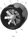
- the propulsion device comprises a cylindrical duct 3 in which the second propeller 2 is comprised, which is therefore an intubed propeller.
- the cylindrical duct 3 preferably has an aerodynamic profile, with a leading edge rounded in the forward direction of the propulsion device, and an inner diameter that progressively decreases and then increases again towards the rear end.
- aerodynamic profile with a leading edge rounded in the forward direction of the propulsion device, and an inner diameter that progressively decreases and then increases again towards the rear end.
- other intubed propeller geometries can be provided.
- the cylindrical duct 3 comprises a fixed part 30 and a rotating part 31, the rotating part 31 being rotatably coupled to the fixed part 30 and rotatably driven by the first motor 5 with respect to said fixed part 30.
- the rotating part 31 is positioned in front of the fixed part 30.
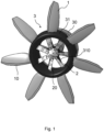
- the first propeller 1 consists of the rotating part 31 and of a plurality of blades 10 arranged externally on the rotating part 31. There are preferably seven blades 10.
- the blades 10 of the first propeller 1 are foldable on the outer surface of the duct 3.
- the seven blades 10 of the first propeller 1 are hinged on the rotating part 31 of the cylindrical duct 3.
- each blade 10 of the first propeller 1 rotates about its own coupling hinge to the rotating part 31.
- the blades 10 are thus arranged radially with respect to the axis of rotation, placing themselves in an active condition.
- the first propeller 1 exerts a propulsion. This is the case for take-off or landing, or vertical or stationary flight.
- a system may be provided for locking the rotating part 31, which is alternatively held stationary by the non-powered motor 5.
- the entire rotating part 31 of the duct 3 rotates and the blades 10 of the first propeller 1, constrained to the rotating part 31, open providing the necessary thrust for vertical flight.
- the rotating part 31 stops rotating and the blades 10 of the first propeller 1 fold over the outer profile of the duct pushed by the aerodynamic air resistance.
- active means for moving the blades 10 from the active condition to the inactive condition and vice versa.
- the second propeller 2 is intubed inside the duct 3 and, by means of the drive of the second motor 6 rotating preferably in the opposite direction to the first motor 5, produces the necessary thrust during the cruising phase.
- the second propeller 2 can also be active during take-off and can be designed to generate the thrust necessary for vertical take-off in the event of failure of the first propeller 1 and/or the first motor 5.
- the second propeller 2 has a plurality of blades 20, e.g., two or more, in particular seven.
- the first propeller 1 is stopped and only the second intubed propeller 2 is operated.
- the power of the second motor 6 and the sizing of the second propeller 2 must allow the necessary thrust to be delivered for take-off and landing.
- the second propeller 2 is driven by the second motor 6 housed in the hub 4, which hub 4 is connected to the fixed part 31 of the duct 3, in a central position to the duct 3 itself, by means of four radially arranged spokes 40.
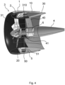
- Figure 4 illustrates a sectional view of the device, with the blades 10 of the first propeller 1 placed in an inactive condition and folded over the duct 3.
- the first electric motor 5 comprises an annular stator 50 fixed on the fixed part 30 of the duct 3 and an annular rotor 51 fixed on the rotating part 31. Activation of the first motor 5 rotates the rotating part 31 with respect to the fixed part 30 and then drives the first propeller 1.
- the first motor 5 is fully integrated into the wall of the cylindrical duct 3.
- the rotating part 31 is rotatably coupled to the fixed part 30 by means of a stator stage 310 for coupling to the hub 4.
- the stator stage 310 is pivotably fixed on the hub 4 by means of bearings, not shown in the figure, in an intermediate tubular portion 41 of the hub 4.
- the first motor 5 can also be positioned on the hub, near said tubular part 41.
- the positioning of the first motor 5 in the thickness of the walls of the duct 3 allows a large diameter of the first motor 5 to be obtained, allowing sections of the stator 50 and the rotor 51 to be reduced, with a decrease in weight and overall size.
- the second motor 6 is placed behind this tubular part 41, whereas the second propeller 2 is placed in front, the second propeller 2 being driven by the second motor 6 by means of a drive shaft passing through said tubular part 41.
- the stator stage 310 is provided with blades inclined opposite to the blades 20 of the second propeller 2, to straighten the rotating air flow generated by the second propeller 2.
- stator stage 310 contributes to the thrust by acting as a further propeller.
- the large diameter of the first propeller 1 allows low-speed rotations. In this way, even during rotation, the stator stage 310 acts as a stator.
- the stator stage 310 contributes to the thrust only as a flow rectifier.
- the propulsion device may be connected to the aircraft by the fixed part 30 of the duct 3 and/or by the hub 4.
Landscapes
- Engineering & Computer Science (AREA)
- Aviation & Aerospace Engineering (AREA)
- Mechanical Engineering (AREA)
- Structures Of Non-Positive Displacement Pumps (AREA)
- Toys (AREA)
Applications Claiming Priority (1)
| Application Number | Priority Date | Filing Date | Title |
|---|---|---|---|
| IT102022000018594A IT202200018594A1 (it) | 2022-09-12 | 2022-09-12 | Dispositivo propulsore aeronautico |
Publications (2)
| Publication Number | Publication Date |
|---|---|
| EP4335744A1 true EP4335744A1 (fr) | 2024-03-13 |
| EP4335744B1 EP4335744B1 (fr) | 2025-07-23 |
Family
ID=84359689
Family Applications (1)
| Application Number | Title | Priority Date | Filing Date |
|---|---|---|---|
| EP23196973.4A Active EP4335744B1 (fr) | 2022-09-12 | 2023-09-12 | Dispositif de propulsion aéronautique |
Country Status (2)
| Country | Link |
|---|---|
| EP (1) | EP4335744B1 (fr) |
| IT (1) | IT202200018594A1 (fr) |
Citations (4)
| Publication number | Priority date | Publication date | Assignee | Title |
|---|---|---|---|---|
| US10287010B2 (en) * | 2016-11-02 | 2019-05-14 | Bell Helicopter Textron Inc. | Rotor sequencing for dual rotor aircraft |
| US10711791B1 (en) * | 2014-04-01 | 2020-07-14 | United States As Represented By The Secretary Of The Air Force | Dual mode turbofan engine |
| EP3760536A1 (fr) | 2019-07-05 | 2021-01-06 | Phase Motion Control S.p.A. | Moyen de propulsion aéronautique |
| US20210253233A1 (en) * | 2020-02-18 | 2021-08-19 | Bell Textron Inc. | Lift engine auxiliary thrust system for stop fold aircraft |
-
2022
- 2022-09-12 IT IT102022000018594A patent/IT202200018594A1/it unknown
-
2023
- 2023-09-12 EP EP23196973.4A patent/EP4335744B1/fr active Active
Patent Citations (4)
| Publication number | Priority date | Publication date | Assignee | Title |
|---|---|---|---|---|
| US10711791B1 (en) * | 2014-04-01 | 2020-07-14 | United States As Represented By The Secretary Of The Air Force | Dual mode turbofan engine |
| US10287010B2 (en) * | 2016-11-02 | 2019-05-14 | Bell Helicopter Textron Inc. | Rotor sequencing for dual rotor aircraft |
| EP3760536A1 (fr) | 2019-07-05 | 2021-01-06 | Phase Motion Control S.p.A. | Moyen de propulsion aéronautique |
| US20210253233A1 (en) * | 2020-02-18 | 2021-08-19 | Bell Textron Inc. | Lift engine auxiliary thrust system for stop fold aircraft |
Also Published As
| Publication number | Publication date |
|---|---|
| EP4335744B1 (fr) | 2025-07-23 |
| IT202200018594A1 (it) | 2024-03-12 |
Similar Documents
| Publication | Publication Date | Title |
|---|---|---|
| US8998125B2 (en) | Method and apparatus for in-flight blade folding | |
| CN112896501B (zh) | 适于垂直起飞和水平飞行的飞行器 | |
| US6450446B1 (en) | Counter rotating circular wing for aircraft | |
| CN107031850B (zh) | 能变几何形状涵道风扇及相关方法 | |
| US6113029A (en) | Aircraft capable of hovering and conventional flight | |
| US11873084B2 (en) | Aircraft with ducted fan and movable louvers over the ducted fan | |
| US12534197B2 (en) | Electric tiltrotor aircraft | |
| JP2021515726A (ja) | 航空機抗力低減システム及び内部冷却電気モータ・システム並びにこれらを使用する航空機 | |
| US4720059A (en) | High speed helicopter | |
| CN109515704B (zh) | 基于摆线桨技术的涵道卷流旋翼飞行器 | |
| CN109018342B (zh) | 转摆线风扇翼装置、倾转摆线风扇翼飞行器及控制方法 | |
| US12037110B2 (en) | Rotary wing aircraft with a shrouded tail propeller | |
| EP4011765B1 (fr) | Aéronef à aile tournante avec une section arrière asymétrique | |
| US11634233B2 (en) | Distributed battery bank for ducted-rotor aircraft | |
| RU2715113C1 (ru) | Электрический привод соосных винтов вертолета (варианты) | |
| CN87105599A (zh) | 垂直起落飞机及其部件 | |
| EP3760536B1 (fr) | Moyen de propulsion aéronautique | |
| CN209581870U (zh) | 基于摆线桨技术的涵道卷流旋翼飞行器 | |
| US11697493B2 (en) | Rotary wing aircraft with a shrouded tail propeller | |
| EP4335744A1 (fr) | Dispositif de propulsion aéronautique | |
| US20240208638A1 (en) | Propulsion system | |
| CN221986593U (zh) | 一种外转子电机开合桨系统 | |
| EP4144637A1 (fr) | Aéronef équipé d'ailes de support pour vol de croisière | |
| US20210316852A1 (en) | Centrifugal fans for vertical take-off and landing (vtol) aircraft propulsion | |
| US12365456B1 (en) | Thruster system for a convertible aircraft |
Legal Events
| Date | Code | Title | Description |
|---|---|---|---|
| PUAI | Public reference made under article 153(3) epc to a published international application that has entered the european phase |
Free format text: ORIGINAL CODE: 0009012 |
|
| STAA | Information on the status of an ep patent application or granted ep patent |
Free format text: STATUS: THE APPLICATION HAS BEEN PUBLISHED |
|
| AK | Designated contracting states |
Kind code of ref document: A1 Designated state(s): AL AT BE BG CH CY CZ DE DK EE ES FI FR GB GR HR HU IE IS IT LI LT LU LV MC ME MK MT NL NO PL PT RO RS SE SI SK SM TR |
|
| STAA | Information on the status of an ep patent application or granted ep patent |
Free format text: STATUS: REQUEST FOR EXAMINATION WAS MADE |
|
| 17P | Request for examination filed |
Effective date: 20240909 |
|
| RBV | Designated contracting states (corrected) |
Designated state(s): AL AT BE BG CH CY CZ DE DK EE ES FI FR GB GR HR HU IE IS IT LI LT LU LV MC ME MK MT NL NO PL PT RO RS SE SI SK SM TR |
|
| GRAP | Despatch of communication of intention to grant a patent |
Free format text: ORIGINAL CODE: EPIDOSNIGR1 |
|
| STAA | Information on the status of an ep patent application or granted ep patent |
Free format text: STATUS: GRANT OF PATENT IS INTENDED |
|
| INTG | Intention to grant announced |
Effective date: 20250214 |
|
| GRAS | Grant fee paid |
Free format text: ORIGINAL CODE: EPIDOSNIGR3 |
|
| GRAA | (expected) grant |
Free format text: ORIGINAL CODE: 0009210 |
|
| STAA | Information on the status of an ep patent application or granted ep patent |
Free format text: STATUS: THE PATENT HAS BEEN GRANTED |
|
| AK | Designated contracting states |
Kind code of ref document: B1 Designated state(s): AL AT BE BG CH CY CZ DE DK EE ES FI FR GB GR HR HU IE IS IT LI LT LU LV MC ME MK MT NL NO PL PT RO RS SE SI SK SM TR |
|
| REG | Reference to a national code |
Ref country code: GB Ref legal event code: FG4D |
|
| REG | Reference to a national code |
Ref country code: CH Ref legal event code: EP |
|
| REG | Reference to a national code |
Ref country code: IE Ref legal event code: FG4D |
|
| REG | Reference to a national code |
Ref country code: DE Ref legal event code: R096 Ref document number: 602023004997 Country of ref document: DE |
|
| PGFP | Annual fee paid to national office [announced via postgrant information from national office to epo] |
Ref country code: AT Payment date: 20251020 Year of fee payment: 3 |
|
| REG | Reference to a national code |
Ref country code: NL Ref legal event code: MP Effective date: 20250723 |
|
| PG25 | Lapsed in a contracting state [announced via postgrant information from national office to epo] |
Ref country code: PT Free format text: LAPSE BECAUSE OF FAILURE TO SUBMIT A TRANSLATION OF THE DESCRIPTION OR TO PAY THE FEE WITHIN THE PRESCRIBED TIME-LIMIT Effective date: 20251124 |
|
| PG25 | Lapsed in a contracting state [announced via postgrant information from national office to epo] |
Ref country code: NL Free format text: LAPSE BECAUSE OF FAILURE TO SUBMIT A TRANSLATION OF THE DESCRIPTION OR TO PAY THE FEE WITHIN THE PRESCRIBED TIME-LIMIT Effective date: 20250723 |
|
| REG | Reference to a national code |
Ref country code: AT Ref legal event code: MK05 Ref document number: 1816191 Country of ref document: AT Kind code of ref document: T Effective date: 20250723 |
|
| PG25 | Lapsed in a contracting state [announced via postgrant information from national office to epo] |
Ref country code: IS Free format text: LAPSE BECAUSE OF FAILURE TO SUBMIT A TRANSLATION OF THE DESCRIPTION OR TO PAY THE FEE WITHIN THE PRESCRIBED TIME-LIMIT Effective date: 20251123 |
|
| PGFP | Annual fee paid to national office [announced via postgrant information from national office to epo] |
Ref country code: DE Payment date: 20251029 Year of fee payment: 3 |
|
| PG25 | Lapsed in a contracting state [announced via postgrant information from national office to epo] |
Ref country code: NO Free format text: LAPSE BECAUSE OF FAILURE TO SUBMIT A TRANSLATION OF THE DESCRIPTION OR TO PAY THE FEE WITHIN THE PRESCRIBED TIME-LIMIT Effective date: 20251023 |
|
| REG | Reference to a national code |
Ref country code: LT Ref legal event code: MG9D |
|
| PG25 | Lapsed in a contracting state [announced via postgrant information from national office to epo] |
Ref country code: AT Free format text: LAPSE BECAUSE OF FAILURE TO SUBMIT A TRANSLATION OF THE DESCRIPTION OR TO PAY THE FEE WITHIN THE PRESCRIBED TIME-LIMIT Effective date: 20250723 |
|
| PG25 | Lapsed in a contracting state [announced via postgrant information from national office to epo] |
Ref country code: FI Free format text: LAPSE BECAUSE OF FAILURE TO SUBMIT A TRANSLATION OF THE DESCRIPTION OR TO PAY THE FEE WITHIN THE PRESCRIBED TIME-LIMIT Effective date: 20250723 |
|
| PG25 | Lapsed in a contracting state [announced via postgrant information from national office to epo] |
Ref country code: HR Free format text: LAPSE BECAUSE OF FAILURE TO SUBMIT A TRANSLATION OF THE DESCRIPTION OR TO PAY THE FEE WITHIN THE PRESCRIBED TIME-LIMIT Effective date: 20250723 |
|
| PGFP | Annual fee paid to national office [announced via postgrant information from national office to epo] |
Ref country code: FR Payment date: 20251027 Year of fee payment: 3 |
|
| PG25 | Lapsed in a contracting state [announced via postgrant information from national office to epo] |
Ref country code: GR Free format text: LAPSE BECAUSE OF FAILURE TO SUBMIT A TRANSLATION OF THE DESCRIPTION OR TO PAY THE FEE WITHIN THE PRESCRIBED TIME-LIMIT Effective date: 20251024 |
|
| PG25 | Lapsed in a contracting state [announced via postgrant information from national office to epo] |
Ref country code: SE Free format text: LAPSE BECAUSE OF FAILURE TO SUBMIT A TRANSLATION OF THE DESCRIPTION OR TO PAY THE FEE WITHIN THE PRESCRIBED TIME-LIMIT Effective date: 20250723 |
|
| PG25 | Lapsed in a contracting state [announced via postgrant information from national office to epo] |
Ref country code: LV Free format text: LAPSE BECAUSE OF FAILURE TO SUBMIT A TRANSLATION OF THE DESCRIPTION OR TO PAY THE FEE WITHIN THE PRESCRIBED TIME-LIMIT Effective date: 20250723 |
|
| PG25 | Lapsed in a contracting state [announced via postgrant information from national office to epo] |
Ref country code: BG Free format text: LAPSE BECAUSE OF FAILURE TO SUBMIT A TRANSLATION OF THE DESCRIPTION OR TO PAY THE FEE WITHIN THE PRESCRIBED TIME-LIMIT Effective date: 20250723 Ref country code: PL Free format text: LAPSE BECAUSE OF FAILURE TO SUBMIT A TRANSLATION OF THE DESCRIPTION OR TO PAY THE FEE WITHIN THE PRESCRIBED TIME-LIMIT Effective date: 20250723 |
|
| PG25 | Lapsed in a contracting state [announced via postgrant information from national office to epo] |
Ref country code: RS Free format text: LAPSE BECAUSE OF FAILURE TO SUBMIT A TRANSLATION OF THE DESCRIPTION OR TO PAY THE FEE WITHIN THE PRESCRIBED TIME-LIMIT Effective date: 20251023 |
|
| PG25 | Lapsed in a contracting state [announced via postgrant information from national office to epo] |
Ref country code: ES Free format text: LAPSE BECAUSE OF FAILURE TO SUBMIT A TRANSLATION OF THE DESCRIPTION OR TO PAY THE FEE WITHIN THE PRESCRIBED TIME-LIMIT Effective date: 20250723 |
|
| PG25 | Lapsed in a contracting state [announced via postgrant information from national office to epo] |
Ref country code: RO Free format text: LAPSE BECAUSE OF FAILURE TO SUBMIT A TRANSLATION OF THE DESCRIPTION OR TO PAY THE FEE WITHIN THE PRESCRIBED TIME-LIMIT Effective date: 20250723 |
|
| PG25 | Lapsed in a contracting state [announced via postgrant information from national office to epo] |
Ref country code: SM Free format text: LAPSE BECAUSE OF FAILURE TO SUBMIT A TRANSLATION OF THE DESCRIPTION OR TO PAY THE FEE WITHIN THE PRESCRIBED TIME-LIMIT Effective date: 20250723 |
|
| PG25 | Lapsed in a contracting state [announced via postgrant information from national office to epo] |
Ref country code: DK Free format text: LAPSE BECAUSE OF FAILURE TO SUBMIT A TRANSLATION OF THE DESCRIPTION OR TO PAY THE FEE WITHIN THE PRESCRIBED TIME-LIMIT Effective date: 20250723 |
|
| PG25 | Lapsed in a contracting state [announced via postgrant information from national office to epo] |
Ref country code: IT Free format text: LAPSE BECAUSE OF FAILURE TO SUBMIT A TRANSLATION OF THE DESCRIPTION OR TO PAY THE FEE WITHIN THE PRESCRIBED TIME-LIMIT Effective date: 20250723 |
|
| PG25 | Lapsed in a contracting state [announced via postgrant information from national office to epo] |
Ref country code: CZ Free format text: LAPSE BECAUSE OF FAILURE TO SUBMIT A TRANSLATION OF THE DESCRIPTION OR TO PAY THE FEE WITHIN THE PRESCRIBED TIME-LIMIT Effective date: 20250723 |
|
| PG25 | Lapsed in a contracting state [announced via postgrant information from national office to epo] |
Ref country code: EE Free format text: LAPSE BECAUSE OF FAILURE TO SUBMIT A TRANSLATION OF THE DESCRIPTION OR TO PAY THE FEE WITHIN THE PRESCRIBED TIME-LIMIT Effective date: 20250723 Ref country code: SK Free format text: LAPSE BECAUSE OF FAILURE TO SUBMIT A TRANSLATION OF THE DESCRIPTION OR TO PAY THE FEE WITHIN THE PRESCRIBED TIME-LIMIT Effective date: 20250723 |