EP4335775A1 - Korrigierbare presspumpe - Google Patents
Korrigierbare presspumpe Download PDFInfo
- Publication number
- EP4335775A1 EP4335775A1 EP22798515.7A EP22798515A EP4335775A1 EP 4335775 A1 EP4335775 A1 EP 4335775A1 EP 22798515 A EP22798515 A EP 22798515A EP 4335775 A1 EP4335775 A1 EP 4335775A1
- Authority
- EP
- European Patent Office
- Prior art keywords
- reset mechanism
- elastic
- piston rod
- supporting ring
- elastic reset
- Prior art date
- Legal status (The legal status is an assumption and is not a legal conclusion. Google has not performed a legal analysis and makes no representation as to the accuracy of the status listed.)
- Pending
Links
Images



Classifications
-
- B—PERFORMING OPERATIONS; TRANSPORTING
- B05—SPRAYING OR ATOMISING IN GENERAL; APPLYING FLUENT MATERIALS TO SURFACES, IN GENERAL
- B05B—SPRAYING APPARATUS; ATOMISING APPARATUS; NOZZLES
- B05B11/00—Single-unit hand-held apparatus in which flow of contents is produced by the muscular force of the operator at the moment of use
- B05B11/01—Single-unit hand-held apparatus in which flow of contents is produced by the muscular force of the operator at the moment of use characterised by the means producing the flow
- B05B11/10—Pump arrangements for transferring the contents from the container to a pump chamber by a sucking effect and forcing the contents out through the dispensing nozzle
- B05B11/1042—Components or details
- B05B11/1073—Springs
- B05B11/1077—Springs characterised by a particular shape or material
-
- B—PERFORMING OPERATIONS; TRANSPORTING
- B05—SPRAYING OR ATOMISING IN GENERAL; APPLYING FLUENT MATERIALS TO SURFACES, IN GENERAL
- B05B—SPRAYING APPARATUS; ATOMISING APPARATUS; NOZZLES
- B05B11/00—Single-unit hand-held apparatus in which flow of contents is produced by the muscular force of the operator at the moment of use
- B05B11/01—Single-unit hand-held apparatus in which flow of contents is produced by the muscular force of the operator at the moment of use characterised by the means producing the flow
- B05B11/10—Pump arrangements for transferring the contents from the container to a pump chamber by a sucking effect and forcing the contents out through the dispensing nozzle
- B05B11/1001—Piston pumps
-
- B—PERFORMING OPERATIONS; TRANSPORTING
- B05—SPRAYING OR ATOMISING IN GENERAL; APPLYING FLUENT MATERIALS TO SURFACES, IN GENERAL
- B05B—SPRAYING APPARATUS; ATOMISING APPARATUS; NOZZLES
- B05B11/00—Single-unit hand-held apparatus in which flow of contents is produced by the muscular force of the operator at the moment of use
- B05B11/01—Single-unit hand-held apparatus in which flow of contents is produced by the muscular force of the operator at the moment of use characterised by the means producing the flow
- B05B11/10—Pump arrangements for transferring the contents from the container to a pump chamber by a sucking effect and forcing the contents out through the dispensing nozzle
- B05B11/1042—Components or details
-
- B—PERFORMING OPERATIONS; TRANSPORTING
- B05—SPRAYING OR ATOMISING IN GENERAL; APPLYING FLUENT MATERIALS TO SURFACES, IN GENERAL
- B05B—SPRAYING APPARATUS; ATOMISING APPARATUS; NOZZLES
- B05B11/00—Single-unit hand-held apparatus in which flow of contents is produced by the muscular force of the operator at the moment of use
- B05B11/01—Single-unit hand-held apparatus in which flow of contents is produced by the muscular force of the operator at the moment of use characterised by the means producing the flow
- B05B11/10—Pump arrangements for transferring the contents from the container to a pump chamber by a sucking effect and forcing the contents out through the dispensing nozzle
- B05B11/1042—Components or details
- B05B11/1043—Sealing or attachment arrangements between pump and container
- B05B11/1046—Sealing or attachment arrangements between pump and container the pump chamber being arranged substantially coaxially to the neck of the container
- B05B11/1047—Sealing or attachment arrangements between pump and container the pump chamber being arranged substantially coaxially to the neck of the container the pump being preassembled as an independent unit before being mounted on the container
-
- B—PERFORMING OPERATIONS; TRANSPORTING
- B05—SPRAYING OR ATOMISING IN GENERAL; APPLYING FLUENT MATERIALS TO SURFACES, IN GENERAL
- B05B—SPRAYING APPARATUS; ATOMISING APPARATUS; NOZZLES
- B05B11/00—Single-unit hand-held apparatus in which flow of contents is produced by the muscular force of the operator at the moment of use
- B05B11/01—Single-unit hand-held apparatus in which flow of contents is produced by the muscular force of the operator at the moment of use characterised by the means producing the flow
- B05B11/10—Pump arrangements for transferring the contents from the container to a pump chamber by a sucking effect and forcing the contents out through the dispensing nozzle
- B05B11/1042—Components or details
- B05B11/1073—Springs
- B05B11/1074—Springs located outside pump chambers
-
- B—PERFORMING OPERATIONS; TRANSPORTING
- B05—SPRAYING OR ATOMISING IN GENERAL; APPLYING FLUENT MATERIALS TO SURFACES, IN GENERAL
- B05B—SPRAYING APPARATUS; ATOMISING APPARATUS; NOZZLES
- B05B11/00—Single-unit hand-held apparatus in which flow of contents is produced by the muscular force of the operator at the moment of use
- B05B11/01—Single-unit hand-held apparatus in which flow of contents is produced by the muscular force of the operator at the moment of use characterised by the means producing the flow
- B05B11/10—Pump arrangements for transferring the contents from the container to a pump chamber by a sucking effect and forcing the contents out through the dispensing nozzle
- B05B11/1001—Piston pumps
- B05B11/1023—Piston pumps having an outlet valve opened by deformation or displacement of the piston relative to its actuating stem
Definitions
- This application relates to a press pump for pumping products, more specifically relates to structural design for an elastic reset mechanism in the press pump.
- Press pump is broadly used in the field such as cosmetics products (for example shower gel, liquid soap, shampoo, etc.), so as to pump products out from the container containing the product for use.
- a primary portion of the press pump is made of elastic, and an elastic reset mechanism is provided therein for resetting the press pump.
- elastic reset mechanism is generally metal spring.
- Metal spring has negative effect on recycling of the press pump. Specifically, because the press pump is an assembly including metal parts and elastic parts, it is to be detached during recycle, which will cause difficulty in recycling the press pump.
- the elastic reset mechanism In order to improve efficiency of recycling the press pump, it is proposed to manufacture the elastic reset mechanism by plastic instead of a metal spring.
- the press pump including elastic spring can be totally made of plastic, which may facilitate in recycling the press pump.
- the elastic reset mechanism made of plastic may face such problem as twist, deflection and the like, in the process of being pressed. Once it is twisted and/or deflected, there will be loss in resilience of the elastic reset mechanism, causing deterioration of the reset ability of the press pump, and even worse, such twist and/or deflection will cause permanent destroy of the elastic reset mechanism, thus the press pump will lost its reset function.
- the present invention is made for overcoming the existing problems in the prior art mentioned above.
- the object of the present invention is to provide a press pump with improved structure, which has the ability of correcting twist and/or deflection of the elastic reset mechanism, so as to improve converting efficiency of resilience of the elastic reset mechanism, and also can prolong service life of the press pump.
- the press pump of the present invention includes a press head, a toothed sleeve and a cylinder, wherein a piston rod is connected below the press head and a piston is mounted on the piston rod, the portion of the piston rod including the piston extending into interior of the cylinder.
- a lateral circumferential wall of the press head cooperates with a lateral circumferential wall of the toothed sleeve to form a reset mechanism containing cavity, in which an elastic reset mechanism is contained, the elastic reset mechanism is supported between the press head and the toothed sleeve, and is provided around the piston rod.
- the elastic reset mechanism includes at least two elastic strips, which ar provided so that each elastic strip is located in close proximity to the piston rod; when the elastic reset mechanism is pressed to deform, in case that the elastic reset mechanism is not twisted or deflected, each elastic strip is elastically deformed in their respective deformation plane; and in case that the elastic reset mechanism is not twisted or deflected, the elastic strips are always free of contacting with inner wall of the reset mechanism containing cavity, at least prior to when the press head is pressed to its lower dead center of the stroke.
- the press pump of the above mentioned structure specifically by means of the provision of the structure and size of the elastic reset mechanism, converting efficiency of resilience during the process of pressing the same can be improved, and the structure enables an automatic correction for the twist or deflection caused from non-uniform in structure, force and the like when being pressed. Specifically, if there is no twist or deflection, the elastic strips will maintain deforming in one deformation plane, and will not contact with the inner wall of the reset mechanism cavity in the whole pressing stroke till the lower dead center, or only contacts with the inner wall just when reaching the lower dead center.
- the elastic strips in the above mentioned press pump is further provided so that in case twist or deflection occurs, the elastic strips can contact with the inner wall during the process of being pressed down and before reaching the lower dead center, such contact with the inner wall will apply a push force to the elastic strips to restore them, thus realizing automatic correction.
- the elastic reset mechanism further includes an upper supporting ring, to which upper ends of the elastic strips are connected, the upper supporting ring being supported on or connected to the press head.
- the elastic reset mechanism further includes a lower supporting ring, to which lower ends of the elastic strips are connected, the lower supporting ring being supported on or connected to the toothed sleeve.
- it can includes two elastic strips.
- a connecting line between the upper supporting points on the supporting ring of the two elastic strips extends through a center of the upper supporting ring.
- a connecting line between the supporting points on the lower supporting ring of the two elastic strips extends through a center of the lower supporting ring.
- the upper supporting ring is rotatable with respect to the upper supporting ring
- the lower supporting ring is rotatable with respect to the toothed sleeve.
- a first mating portion is formed on the upper supporting ring and/or lower supporting ring
- a second mating portion is formed on the piston rod
- one of the first mating portion and the second mating portion is a groove
- the other of the first mating portion and the second mating portion is a rib extending axially along the piston rod.
- the first mating portion is a hole with interior gear
- the second mating portion is a shaft with exterior gear
- Figs. 1-8 show a press pump 100 of the first embodiment of the present invention.
- Figs. 1a-1c show cutaway views of the press pump 100 in various states, in which the press pump 100 in Fig. 1c is at its upper dead center of the stroke, the press pump 100 in Fig. 1b is in its stoke of being pressed down and the press pump 100 in Fig. 1c is at its lower dead center of the stroke.
- the press pump 100 includes a press head 110, a toothed sleeve 120 and a cylinder 130.
- the toothed sleeve 120 and the cylinder 130 are connected together.
- a piston rod 140 is provided below the press head 110, the piston rod 140 can be formed integrally below the press head 110 as shown in the drawings, or can be a separate part connected below the press head 110.
- a piston 141 is mounted on the piston rod 140, for example on the piston rod 140, for example the piston 141 can be mounted at or near a lower end of the piston rod 140.
- a portion of the piston rod 140 including the piston 141 extends into interior space of the cylinder 130.
- a lateral circumferential wall of the press head 220 cooperates with a lateral circumferential wall of the toothed sleeve 120 to form a reset mechanism containing cavity 160, in which an elastic reset mechanism 150 of the press pump 100 is contained.
- the elastic reset mechanism 150 is supported between the press head 110 and the toothed sleeve 120, and is located around the piston rod 140.
- the press head 110 includes a top inner surface 110, an upper end of the elastic reset mechanism 150 can abut against or be connected to the top inner surface 111.
- a step 121 is provided within the toothed sleeve 120, a lower end of the elastic rest mechanism 150 can abut against or be connected to the step 121.
- Figs. 5a-5c respectively show front view, side view and perspective view of the elastic reset mechanism 150.
- the elastic reset mechanism 150 includes a plurality of elastic strips 151.
- the elastic reset mechanism 150 includes two elastic strips 151.
- the planes in which the two elastic strips 151 respectively lie are preferably parallel to each other, as shown in Fig. 5b .
- the elastic reset mechanism 150 can includes other number of elastic strips, which is more than two, for example three, four and so on, these cases are also included in the scope of the present invention.
- Upper ends of the respective elastic strips 151 can be connected on an upper supporting ring 152, which is supported on the press head 110.
- Lower ends of the elastic strips 151 are connected on a lower supporting ring 153, which is supported on the elastic reset mechanism 150.
- the upper supporting ring 152 can be omitted, so that the upper ends of the elastic strips 151 directly contact with or are connected to the press head 110.
- the lower supporting ring 153 can be omitted, so that the lower ends of the elastic strips 151 directly contact with or are connected to the toothed sleeve 120.
- the size and the structure of the elastic reset mechanism 150 is improved.
- the elastic strip 151 is in one deforming plane P.
- the elastic reset mechanism 150 is pressed to deform, in case that no twist or deflection occurs to the elastic reset mechanism 150, the elastic strip 151 is always elastically deformed in this deforming plane P.
- the deformation of the elastic strips 151 in one plane can be obtained by arranging the elastic strips 151 to be symmetrical to each other with respect to the axis of the elastic reset mechanism 150.
- a connecting line between the pivot points of the two elastic strips 151 on the upper supporting ring 152 can extend through a center of the upper supporting ring 152.
- a connecting line between the pivot points of the elastic strips 151 on the lower supporting ring 153 can also extends through a center of the lower supporting ring 153.
- Figs. 7 and 8 respectively show schematic perspective view of the elastic reset mechanism 150 assembled together with the press head 110 and the toothed sleeve 120.
- the upper supporting ring 152 of the elastic reset mechanism 150 supports on or is connected to a top inner surface 111 of the press head 110
- the lower supporting ring 153 of the elastic reset mechanism 150 supports on or is connected to a step 121 of the toothed sleeve 120.
- the elastic strips 151 are disposed in close proximity to the piston rod 140. Also, the elastic strips 151 are sized so that when the elastic strips 151 are pressed down to deform, in case no twist or deflection occurs to the elastic reset mechanism 150, the elastic strips 151 is always free of contact with the inner wall 161 of the reset mechanism containing cavity 160 at least before the press head 110 is pressed to the lower dead center shown in Fig. 1c .
- the elastic strips 151 may be free of contact with the inner wall 161 during the whole pressing down stroke, including at the lower dead center of the stroke; or, the elastic strips 151 contact with the inner wall 161 only when the press head 110 just reaches its lower dead center of the stroke, and before that point, the elastic strips 151 is free of contact with the inner wall 161.
- the inner wall 161 is consisted of at least one of the inner wall surface of the side circumferential wall of the press head 110 and the inner wall surface of the side circumferential wall of the toothed sleeve 120.
- the elastic strips 151 twist during the process of being pressed down, the elastic strips 151 can contact with the inner wall 161 prior to reaching the lower dead center of the stroke. At this time, such contact between the inner wall 161 and the elastic strips 151 will apply a push force on the elastic strips 151, which pushes the elastic strip 151 to a position in close abutment with the piston rod 140, thus automatic correction occurs.
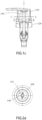
- FIG. 1a shows a press pump 100 in its upper dead center of the stroke
- FIG.2a is a cutaway view obtained along line A-A of FIG. 1a
- the elastic reset mechanism 150 is in its relaxed state, and its elastic strips 151 are in close proximity to the piston rod 140.
- unevenness of the force may result from various reasons, for example it is impossible for the user to apply press in a direction perfectly coincide with the axis of the press pump 100, and there is often a slight angle; for another example, the mass, degree of curve, density of the individual elastic strip 151 etc., may slightly varied, which results in difference in the amount of deformation and resilient produced when just one press force is applied; and so on .
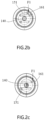
- At least one elastic strip 151 may disengage from the piston rod 140 and offset towards the inner wall 161 of the reset mechanism containing cavity 160, as shown in Fig. 2b .
- Fig. 2b shows a cutaway view obtained along the line B-B in Fig. 1b .
- the elastic strip 151 will contact with the inner wall because of the twist of the elastic reset mechanism 150.
- the elastic strips 151 are sized so that it will always free of contact with the inner wall 161 when no twist or deflection occurs and the elastic strips 151 are in close proximity to the piston rod 140, when the elastic strips 151 contact the inner wall 161 because of twist or deflection of the elastic reset mechanism 150, the inner wall 161 will apply a correction force (or in other words push force) F1 on the elastic strips 151 towards the piston rod 140, so that the elastic strips 151 will return back in a direction towards the piston rod 140, as shown in Fig. 2c .
- the elastic strips 151 of the elastic reset mechanism 150 can be corrected to the state of deforming in the same plane and in close proximity to the piston rod, by means of providing the elastic strips 151 in such a way that in the process of being pressed, they are always free of contact with the inner wall 161 of the reset mechanism containing cavity 160 until reaching the lower dead center of the stroke, and thus a sound resilience converting efficiency of the elastic reset mechanism 150 can be obtained, its reset ability can be improved. And, by means of correction to the twist of the elastic reset mechanism 150, the service life of the elastic reset mechanism 150 can be prolonged.
- Figs. 9-11 show a second embodiment of the present application, in which perspective views of the press head 210, the elastic reset mechanism 250 of the press pump, as well as their assembled state of the second embodiment are shown.
- the second embodiment different from those of the first embodiment will be described in detail, and unless it is illustrated in contrary or conflicts with the other features, the features described in the first embodiment may also apply to the second embodiment, and will not be described in detail hereinafter.
- the elastic reset mechanism 250 of the press pump of the second embodiment includes a plurality of (two in the embodiment shown) elastic strips 251, the upper and lower ends of the elastic strips 251 respectively are connected to the upper supporting ring 252 and lower supporting ring 253.
- a first mating portion in the form of a notch 254 is provided on at least one of the upper supporting ring 252 and the lower supporting ring 253.
- Fig. 10 shows a press head 210 of the press pump of the second embodiment.
- a piston rod 240 is connected below the press head 210, on an outer surface of which a second mating portion axially extending along the piston rod 240 is formed, the second mating portion is for example a rib 241 shown in the drawings.
- the elastic reset mechanism 250 and the press head 210 are assembled together, as shown in Fig. 11 , the elastic reset mechanism 250 is sleeved onto the piston rod 240, and the notch 254 engages with the rib 241, forming a synchronous structure, which enables the upper supporting ring 252 and the lower supporting ring 253 of the synchronous structure to rotate synchronously, thus the elastic reset mechanism 250 can be free of twist.
- each elastic strip 251 of the elastic reset mechanism 250 may be uneven, or since some difference in terms of shape, density and so on produced due to manufacturing tolerance, the elastic reset mechanism 250 will be slightly deflected as a whole, so that the elastic strips 251 leave from the piston rod 240 and deflect towards the inner wall of the reset mechanism containing cavity, similar to the elastic strips 151 in Figs. 2a-2c of the first embodiment. And, identically, the elastic strips 251 is also sized and shaped similarly to the elastic strips 151 of the first embodiment, so in the second embodiment, the deflection due to the elastic reset mechanism 250 will also be automatically corrected.
- Figs. 12-14 show a third embodiment of the present application, in which perspective views of the press head 310, the elastic reset mechanism 350 of the press pump, as well as their assembled state of the third embodiment are shown.
- the third embodiment different from those of the first and second embodiments will be described in detail, and unless it is illustrated in contrary or conflicts with the other features, the features described in the first and second embodiments may also apply to the third embodiment, and will not described in detail hereinafter.
- the press pump of the third embodiment also includes a synchronous structure.
- the elastic reset mechanism 350 includes a plurality of elastic strips 351, upper ends of the elastic strips 351 are coupled to an upper supporting ring 352, lower ends thereof are coupled to a lower supporting ring 353, wherein a hole 354 with interior gear, as a first mating portion, is formed on at least one of the upper supporting ring 352 and the lower supporting ring 353.
- the piston rod 340 connected to the press head 310 is formed in the shape of a shaft with exterior gear.
- the piston rod 340 in the form of a shaft with exterior gear cooperates with the hole 354 with interior gear in the upper supporting ring 352 and the lower supporting ring 353 of the elastic reset mechanism 350 to form a synchronous mechanism, so that the elastic reset mechanism 350 is able to synchronously rotate with the press head 310 and the piston rod 340, thus no twist occurs.
- the elastic reset mechanism 350 may deflect when subjected to a press force, and the structure of the press pump of the third embodiment identically has the ability of correcting such deflection, as described in relation to the second embodiment.
Landscapes
- Reciprocating Pumps (AREA)
- Closures For Containers (AREA)
Applications Claiming Priority (2)
| Application Number | Priority Date | Filing Date | Title |
|---|---|---|---|
| CN202110494340.4A CN113716204B (zh) | 2021-05-07 | 2021-05-07 | 一种可矫正的按压泵 |
| PCT/CN2022/077049 WO2022233173A1 (zh) | 2021-05-07 | 2022-02-21 | 一种可矫正的按压泵 |
Publications (2)
| Publication Number | Publication Date |
|---|---|
| EP4335775A1 true EP4335775A1 (de) | 2024-03-13 |
| EP4335775A4 EP4335775A4 (de) | 2025-05-07 |
Family
ID=78672700
Family Applications (1)
| Application Number | Title | Priority Date | Filing Date |
|---|---|---|---|
| EP22798515.7A Pending EP4335775A4 (de) | 2021-05-07 | 2022-02-21 | Korrigierbare presspumpe |
Country Status (6)
| Country | Link |
|---|---|
| US (1) | US20240278272A1 (de) |
| EP (1) | EP4335775A4 (de) |
| JP (1) | JP7815274B2 (de) |
| KR (1) | KR20240004374A (de) |
| CN (1) | CN113716204B (de) |
| WO (1) | WO2022233173A1 (de) |
Families Citing this family (2)
| Publication number | Priority date | Publication date | Assignee | Title |
|---|---|---|---|---|
| CN113716204B (zh) * | 2021-05-07 | 2024-02-06 | 丁要武 | 一种可矫正的按压泵 |
| CN117259051A (zh) * | 2023-09-22 | 2023-12-22 | 天舟医疗(苏州)有限公司 | 一种弹簧组及包括该弹簧组的按压泵 |
Family Cites Families (17)
| Publication number | Priority date | Publication date | Assignee | Title |
|---|---|---|---|---|
| DE3134265A1 (de) * | 1981-08-29 | 1983-03-10 | Robert Finke KG, 5950 Finnentrop | Auf behaelter aufsetzbare pumpe |
| FR2921050A1 (fr) * | 2007-09-13 | 2009-03-20 | Oreal | Pompe distributrice pour recipient de stockage et de distribution de produit et recipient pourvu d'une telle pompe |
| JP4862925B2 (ja) * | 2009-07-31 | 2012-01-25 | 株式会社富士通ゼネラル | ロータリ圧縮機 |
| WO2013142871A1 (en) * | 2012-03-23 | 2013-09-26 | Ddps Global, Llc | Compression spring and pump for dispensing fluid |
| CN103420022B (zh) * | 2012-05-16 | 2015-09-09 | 丁要武 | 按压式液体泵 |
| CN202621361U (zh) * | 2012-05-16 | 2012-12-26 | 丁要武 | 按压式液体泵 |
| CN202591008U (zh) * | 2012-05-16 | 2012-12-12 | 丁要武 | 按压式液体泵 |
| CN107000284B (zh) * | 2014-11-20 | 2020-08-07 | 泰普勒斯特股份公司 | 一种弹性元件以及用于制造所述弹性元件的方法和铸模 |
| CN109809027B (zh) * | 2017-11-21 | 2024-09-13 | 丁要武 | 无弹簧泵和包括该无弹簧泵的容器 |
| CN109809026B (zh) * | 2017-11-21 | 2024-12-27 | 丁要武 | 液体泵 |
| CN120421139A (zh) * | 2019-01-03 | 2025-08-05 | 丁要武 | 乳液泵 |
| CN111392231B (zh) * | 2019-01-03 | 2025-08-08 | 丁要武 | 乳液泵 |
| CN112340222B (zh) * | 2019-08-08 | 2025-01-21 | 丁要武 | 泵送装置 |
| CN211811088U (zh) * | 2019-11-12 | 2020-10-30 | 丁要武 | 囊式输送泵 |
| CN212939919U (zh) * | 2020-04-28 | 2021-04-13 | 刘和祥 | 一种足踝外科下胫腓关节复位固定导向器 |
| KR102206983B1 (ko) * | 2020-04-29 | 2021-01-25 | 주식회사 동기피엔아이 | 논메탈 타입 화장품 용기의 펌프 어셈블리 |
| CN113716204B (zh) * | 2021-05-07 | 2024-02-06 | 丁要武 | 一种可矫正的按压泵 |
-
2021
- 2021-05-07 CN CN202110494340.4A patent/CN113716204B/zh active Active
-
2022
- 2022-02-21 WO PCT/CN2022/077049 patent/WO2022233173A1/zh not_active Ceased
- 2022-02-21 JP JP2023565417A patent/JP7815274B2/ja active Active
- 2022-02-21 EP EP22798515.7A patent/EP4335775A4/de active Pending
- 2022-02-21 US US18/558,205 patent/US20240278272A1/en active Pending
- 2022-02-21 KR KR1020237037011A patent/KR20240004374A/ko active Pending
Also Published As
| Publication number | Publication date |
|---|---|
| JP7815274B2 (ja) | 2026-02-17 |
| US20240278272A1 (en) | 2024-08-22 |
| WO2022233173A1 (zh) | 2022-11-10 |
| JP2024519685A (ja) | 2024-05-21 |
| KR20240004374A (ko) | 2024-01-11 |
| CN113716204A (zh) | 2021-11-30 |
| CN113716204B (zh) | 2024-02-06 |
| EP4335775A4 (de) | 2025-05-07 |
Similar Documents
| Publication | Publication Date | Title |
|---|---|---|
| EP4335775A1 (de) | Korrigierbare presspumpe | |
| JP6663408B2 (ja) | 押圧式液体ポンプ | |
| WO2022126501A1 (zh) | 塑料弹簧、泵芯、乳液泵及按压式包装容器 | |
| CN114537879B (zh) | 按压式液体泵 | |
| CN112340222A (zh) | 泵送装置 | |
| CN213769721U (zh) | 按压式液体泵 | |
| CN112628330B (zh) | 塑料弹簧、泵芯、乳液泵及按压式包装容器 | |
| CN117259051A (zh) | 一种弹簧组及包括该弹簧组的按压泵 | |
| US12325034B2 (en) | Cosmetic container | |
| CN210455795U (zh) | 泵送装置 | |
| WO2025247134A1 (zh) | 弹性复位机构以及包括该弹性复位机构的按压泵 | |
| US7918262B2 (en) | Tape cutting dispenser | |
| KR102384142B1 (ko) | 회전형 화장품 케이스 | |
| EP3662977A1 (de) | Trampolinträgerrahmen mit biegbaren stützbeinen | |
| CN119158721A (zh) | 一种弹性复位机构以及包括其的按压泵 | |
| CN215923105U (zh) | 弹性复位机构及包括该弹性复位机构的按压泵 | |
| JP2573038Y2 (ja) | 摺動用パッキン | |
| JP2024506055A (ja) | 弾性復帰機構および該弾性復帰機構を備える押圧ポンプ | |
| JP5410280B2 (ja) | ピストンアセンブリ用のピストン部分及びピストンアセンブリ | |
| CN223491180U (zh) | 一种弹性复位机构以及包括其的按压泵 | |
| CN216789066U (zh) | 制动主缸的活塞总成 | |
| JPH062788Y2 (ja) | 弁付塗布具の弁開放機構 | |
| CN221380862U (zh) | 边框组件和太阳能板 | |
| CN219086940U (zh) | 一种离合齿轮组件及减速电机 | |
| CN211577529U (zh) | 光学成像系统 |
Legal Events
| Date | Code | Title | Description |
|---|---|---|---|
| STAA | Information on the status of an ep patent application or granted ep patent |
Free format text: STATUS: THE INTERNATIONAL PUBLICATION HAS BEEN MADE |
|
| PUAI | Public reference made under article 153(3) epc to a published international application that has entered the european phase |
Free format text: ORIGINAL CODE: 0009012 |
|
| STAA | Information on the status of an ep patent application or granted ep patent |
Free format text: STATUS: REQUEST FOR EXAMINATION WAS MADE |
|
| 17P | Request for examination filed |
Effective date: 20231106 |
|
| AK | Designated contracting states |
Kind code of ref document: A1 Designated state(s): AL AT BE BG CH CY CZ DE DK EE ES FI FR GB GR HR HU IE IS IT LI LT LU LV MC MK MT NL NO PL PT RO RS SE SI SK SM TR |
|
| DAV | Request for validation of the european patent (deleted) | ||
| DAX | Request for extension of the european patent (deleted) | ||
| REG | Reference to a national code |
Ref country code: DE Ref legal event code: R079 Free format text: PREVIOUS MAIN CLASS: B65D0047340000 Ipc: B05B0011100000 |
|
| A4 | Supplementary search report drawn up and despatched |
Effective date: 20250407 |
|
| RIC1 | Information provided on ipc code assigned before grant |
Ipc: B05B 11/10 20230101AFI20250401BHEP |