EP4335781A1 - Tank zur lagerung von behältern - Google Patents
Tank zur lagerung von behältern Download PDFInfo
- Publication number
- EP4335781A1 EP4335781A1 EP23187616.0A EP23187616A EP4335781A1 EP 4335781 A1 EP4335781 A1 EP 4335781A1 EP 23187616 A EP23187616 A EP 23187616A EP 4335781 A1 EP4335781 A1 EP 4335781A1
- Authority
- EP
- European Patent Office
- Prior art keywords
- pair
- crosspiece
- crosspieces
- grid
- tank
- Prior art date
- Legal status (The legal status is an assumption and is not a legal conclusion. Google has not performed a legal analysis and makes no representation as to the accuracy of the status listed.)
- Pending
Links
Images




Classifications
-
- B—PERFORMING OPERATIONS; TRANSPORTING
- B65—CONVEYING; PACKING; STORING; HANDLING THIN OR FILAMENTARY MATERIAL
- B65D—CONTAINERS FOR STORAGE OR TRANSPORT OF ARTICLES OR MATERIALS, e.g. BAGS, BARRELS, BOTTLES, BOXES, CANS, CARTONS, CRATES, DRUMS, JARS, TANKS, HOPPERS, FORWARDING CONTAINERS; ACCESSORIES, CLOSURES, OR FITTINGS THEREFOR; PACKAGING ELEMENTS; PACKAGES
- B65D90/00—Component parts, details or accessories for large containers
- B65D90/22—Safety features
- B65D90/24—Spillage-retaining means, e.g. recovery ponds
Definitions
- the present invention relates to a tank for storing containers.
- examples of stored materials may be petrol, refrigerating liquid and oils, paints, liquid soaps and detergents which are generally commercially supplied in containers, for example cans, barrels, drums.
- the storage materials in addition to those indicated, may be solid materials, such as sawdust, chips or raw materials in the form of granules, or of a gaseous nature such as flame retardants or cooling gases.
- the aforementioned containers when they must not be used, are stored inside cabinets or collection tanks.
- the containers are stored in tanks forming supply areas where users go to perform liquid tapping or transfer operations into smaller transport units to be handled within the work environments. For example, it may happen that a barrel of liquid for radiators is stored in the tank located inside a garage, from which several mechanics draw to withdraw a quantity so as to bring it near a respective vehicle repair station.
- the collection tank is therefore one of the most popular shelter systems because it has a liquid recovery and containment compartment at its base. By means of the recovery compartment, the liquids which exit from the containers, in some cases due to damage and deterioration of the containers, in other cases due to clumsy or incomplete withdrawal manoeuvres, are not dispersed in the environment surrounding the tank.
- the collection tanks of the prior art generally consist of a box-like body defining the liquid collection compartment therein.
- the box-like body is defined by a plurality of walls, joined together, closed below by a bottom. Opposite the bottom, the box-like body has an upper opening.
- a grid defining a rest plane for the containers is located on the opening.
- the grid also called grille, is a monolithic element, generally made of steel, with an internal space divided by a first series of first bars, spaced and parallel to each other, crossed perpendicularly to a second series of bars, spaced and parallel to each other.
- the first and second series of bars also known in the market as loadbearing plates and transverse connections, define a plurality of links each underlying an opening therein through which a material, liquid or solid, can pass, to be collected on the bottom of the tank.
- the tanks of the prior art have a disadvantage linked to the reduced transport flexibility in the packaging and shipping process.
- the box-like body can be broken down into a desired number of pieces, generally bottom and sides, to reduce the dimensions of the tank
- the grid being monolithic, cannot be split into subunits.
- the tank which when assembled would occupy the maximum dimensions, could be sent disassembled to reduce the overall dimensions of the packaging, but the grid makes this optimization of spaces impractical. This is because the disassembled box-like body may require a short time for assembly by unskilled labour, while the grid would require specialised personnel and long assembly times.
- the box-like body could be assembled by means of operations of interlocking or screwing the side walls to the bottom, while the assembly of the grid would require a positioning mask of the plates and the parallel and perpendicular transverse connections therebetween and the fixing would require the intervention of a skilled welder.
- the tanks are currently packaged assembled or substantially pre-finished for shipment with the grid already formed and installed by the manufacturer. As indicated above, this entails several disadvantages.
- the overall dimensions of the mounted tank make the packaging very bulky and thus very expensive to ship.
- the manufacturer finds it uneconomical to send one or more tanks beyond a certain distance from its location.
- the weight and the overall dimensions of the grid make it a body which can deform, scratch and damage the other elements of the tank during the shipment thereof.
- the technical task of the present invention is thus to provide a tank for storing containers which is able to overcome the prior-art drawbacks which have emerged.
- an object of the present invention is to provide a tank for storing containers, which can be dismantled when it must be shipped and which has contained overall dimensions to facilitate the packaging and shipping operations.
- a further object of the present invention is to provide a tank for storing containers which is provided with a light grid, which is easy to install on the tank once it has reached the destination.
- the set technical task and aims are substantially attained by a tank for storing containers comprising the technical characteristics set out in one or more of the appended claims.
- 1 overall indicates a tank for storing containers C. Storage is intended as the temporary storage of the container C, and the material contained therein, until a subsequent movement of the container C to a different location or the temporary storage of the container C for the withdrawal of the material contained therein, when necessary.
- the function of the tank 1 is to create a temporary container location station, while in the second case, the function of the tank 1 is to create a material supply station.
- the containers C can contain the most disparate materials in liquid, solid or gaseous state, such as oils, fuels, lubricants, detergents or sawdust, chips, raw materials in granular form, or flame retardant or refrigerant gases.
- the tank 1 is defined by a box-like body 2, open above with an opening 3 and enclosing a compartment V open above therein.
- the box-like body 2 comprises a bottom 4 which can include a flat extension or include inclined surfaces to favour the conveying of the collected material towards a specific area of the bottom itself (possibly provided with a drain hole, closed by a cap and openable during material recovery operations).
- a side flank 5 extends from the bottom 4, which laterally delimits the compartment V.
- Figure 1 depicts a preferred shape of the box-like body 2 of parallelepiped shape, by means of which the side flank 5 is composed of a first pair of walls 51, spaced from each other and preferably parallel, connected to a second pair of walls 52, spaced from each other and preferably parallel. That is, the first and second pair of walls 51,52 are connected to each other so as to define in cross-section, passing through a plane parallel and spaced from the bottom 3, a closed quadrangular contour adapted to laterally delimit the compartment V.
- the box-like body 2 can have any shape, such as cylindrical or pyramidal trunk, as long the condition is respected in which the side flank 5 has, on a section plane parallel to the bottom 3, a closed contour.
- support elements 10 Connected to the bottom 4, on the side opposite the compartment V, i.e., outside the tank 1, there are support elements 10, preferably defined by a set of four support feet, to maintain the tank 1, in particular the bottom 4, lifted from a rest plane and to facilitate the movement of the tank 1 for example by means of the forks of a forklift.
- the pair of support elements 6 is arranged on opposite sides of the side flank 5, in particular at the first pair of walls 51, and faces the inside of the compartment V.
- the support elements 6 can be connected, by means of fixing, welding or other means, on shelves located inside the side flank 5 or through a quadrangular frame connected inside the side flank 5.
- the tank 1 can include one pair of support elements 6 on the second pair of side walls 52, or further two pairs of support elements 6 with each support element arranged on a respective side wall.
- the pair of support elements 6 is defined by a first elongated bar 61 and a second elongated bar 62.
- the first and second elongated bars 61,62 are parallel to each other arranged along a pair of generatrices X parallel to each other.
- Each elongated bar 61,62, illustrated in figure 7 is defined by an element having a predominant dimension with respect to the other two. In figure 7 it can be noted how the extension along the generatrix X is predominant with respect to the dimensions of the base and height of the cross section.
- the cross section of each elongated bar is preferably rectangular but, without departing from the scope of protection of the present invention, can have any shape, e.g., square or round section.
- Each elongated bar 61,62 has a respective plurality of first and second slits 610, 620 which extend from an upper end of the bar up to reaching about half the height of the bar itself. That is, the slits 610, 620 are blind at an intermediate height of the low and open above to communicate with the opening 3 of the box-like body 2.
- the first plurality of slits 610 is associated with the first elongated bar 61 and the second plurality of slits 620 is associated with the second elongated bar 62.
- a grid 7 is placed abutting against the pair of support elements 6 which, given the location of the support elements 6, lies near the opening 3.
- Said grid 7 defines a rest plane for any containers C placed thereabove. As a result of a plurality of discharge slits 8, the grid 7 partially closes the opening 3 and thus above the compartment V of the box-like body 2.
- any liquid and/or debris exiting from the containers C resting on the grid 7 crosses the grid 7 and is collected inside the compartment V of the box-like body 2.
- the grid 7 is defined by a plurality of crosspieces 9 arranged parallel to each other and resulting rested, on opposite sides, on the pair of support elements 6.
- Each crosspiece belonging to the plurality of crosspieces 9 is spaced from a contiguous crosspiece so as to define a corresponding discharge slit 8 therebetween.
- Each crosspiece 9 belonging to the plurality of crosspieces 9 is singly separable from the pair of support elements 6 and from the other crosspieces 9 to enable the dimension volumes of the grid 7 to be reduced when dismantled from the tank 1. That is, when the tank 1 is dismantled, for example for shipping needs, the grid 7 can be dismantled into a plurality of single crosspieces 9. The latter can be located inside the box-like body 2. The formation and subsequent installation of the grid 7 does not occur entirely covering the opening 3 of the box-like body 2 due to the laying of a monolithic element but occurs gradually, connecting one crosspiece after the other on the pair of support elements 6.
- the grid 7 can assume two configurations of use: an assembled configuration, in which the plurality of crosspieces 9 is connected to the pair of support elements 6 so that each crosspiece is substantially coplanar to the adjacent crosspieces, and a disassembled configuration, in which the plurality of crosspieces 9 is disconnected from the pair of support elements 6 and the crosspieces can be placed inside the box-like body so as to arrange the tank 1 ready to be packaged and shipped.
- the assembled configuration is implemented by positioning one crosspiece at a time 9 between the pair of support elements 6 and the disassembled configuration occurs by extracting one crosspiece at a time from the pair of support elements 6.
- each crosspiece belonging to the plurality of crosspieces 9 has a main extension axis Y.
- the main extension of each crosspiece 9 along the axis Y causes the plurality of crosspieces 9 to be located on the pair of support elements 6 lying transversely, preferably perpendicular, to the extension axes X of the first and second elongated bar 61,62.
- each slit belonging to the plurality of discharge slits 8, obtained from the spacing of a pair of contiguous crosspieces 9, also has extension along an axis parallel to the main extension axis Y of the crosspieces.
- FIG 6 a first crosspiece variant 9 is depicted, while in figure 8 a second crosspiece variant 9 is illustrated.
- the common parts of both variants will be described below.
- the crosspiece 9 has a planar surface 90 above defining, together with other planar surfaces belonging to other respective crosspieces 9, the rest plane of the grid 7.
- a head portion 91 reversibly engageable with a support element belonging to the pair of support elements 6.
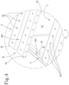
- the planar surface 90 has a pair of folds 93 on opposite sides, which are parallel to one another and extending along the main extension axis Y from the head portion 91 to the bottom portion 92.
- Each fold 93 angled with respect to the planar surface 90, preferably at a right angle, ends with a hooked body or with a body with hook.
- the first pair of hooked bodies 94 is preferably connectable to the first elongated bar 61 while the second pair of hooked bodies 95 is preferably connected to the second elongated bar 62.
- the shape of the first pair of hooked bodies 94 is such as to generate a free space subtended within a curved section of the hooked portion. Such a space can be occupied by the transverse section of the first elongated bar 61. This coupling occurs in the same manner between the second pair of hooked bodies 95 and the transverse section of the second elongated bar 62.
- each crosspiece 9 is inhibited from moving along the main extension axis Y.
- each crosspiece 9 it is then possible to constrain the movement of each crosspiece 9 also along a direction incident to the main extension axis Y. To do this, it is necessary to couple the hooked bodies with corresponding slits obtained on the first and second elongated bar.
- first pair of hooked bodies 94 is coupled, with shape coupling, inside a pair of first slits 610 while the second pair of hooked bodies 95 is coupled, with shape coupling, inside a pair of second slits 620.
- first and second slits 610, 620, together with first and second pair of hooked bodies 94,95 constrain the crosspieces 9 on the pair of support elements 6, preventing translating movements of each crosspiece along directions transverse to the axis Y.
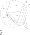
- the planar surface 90 can be divided into a first section 901 and a second section 902, spaced apart and joined by a groove 903.
- the transverse section of the groove 903 is preferably V-shaped and ends with a vertex 904 located at a lower height with respect to that subtended by the planar surface 90, i.e., at the height subtended by the pair of sections 901, 902.
- the cross-section of the crosspiece 9 has a vertical section, defined by one of the folds 93, a horizontal section, defined by the first section 901 of the planar surface 90, a V-shaped section, defined by the groove 903 ending below with the vertex 904, again a horizontal section, defined by the second section 902 of the planar surface 90, and again a vertical section, defined by the other fold 93.
- the vertex 904 is perceptible in section as a point-like element, but throughout the three-dimensional extension of the crosspiece 9 it extends as a linear recess.
- each crosspiece 9 is interrupted to prevent any material from accumulating and stagnating on a flat surface.
- the liquid exiting the container C can be conveyed therein, accumulating on the vertex 904.
- each crosspiece 9 it is preferable to make a plurality of discharge holes thereon.
- Figure 6 shows a crosspiece 9 provided with a first plurality of discharge holes 96 uniformly spaced on at least the planar surface 90, preferably uniformly distributed on the first and second section 901 and 902 of the planar surface 90.
- a second plurality of discharge holes 97 may be included at the groove 903 preferably located at the vertex 903.
- the crosspiece 9 is preferably lacking the plurality of discharge holes 96 or 97.
- the crosspiece of figure 8 is preferably used to favour the loading of solid material in granular format, for example a plastic material, inside collection bags.
- the crosspiece 9 maintaining the function of supporting the load above the box-like body 2, has the purpose of preventing, as far as possible, the granular material from falling inside the compartment V, mixing with waste liquids, consequently becoming irrecoverable.
- the granular material which has exited from a bag container falls onto the crosspiece itself, at the planar surface 90 or the groove 903, and, once the bag is removed, could be recovered to be transferred into another bag of raw materials.
- the crosspiece 9 of figure 8 differs from the crosspiece 9 of figure 6 for a different location of first and second pair of hooked bodies 94, 95 with respect to the extension along the axis Y of head and bottom portion 91,92 of the crosspiece.
- the first pair of hooked bodies 94 is protruding with respect to a vertical cutting plane of the head portion 90. That is, the underlying spacing A between the first pair of hooked bodies 94 and the second pair of hooked bodies 95, measured as a distance along the axis Y, is greater than the underlying spacing B between the head portion 90 and the bottom portion 91, measured as a maximum distance along the axis Y of the crosspiece 9.
- the crosspiece 9 is coupled between the pair of support elements 6, at the opposite ends of the crosspiece 9, i.e., between the head portion 91 and relative support element 6 and bottom portion 92 and relative support element 6, two outlet openings are generated which facilitate the conveyance of liquid towards the compartment V.
- crosspiece is sheared at the ends, at the head portion 91 and bottom portion 92 with two vertical planes.
- the first and second pair of hooked bodies 94, 95 end having a spacing B, measured as a distance along the axis Y, greater than an extension A of the groove 903 and of the planar surface 90, always measured along the axis Y.
- a pair of slots 905 is included, obtained at the vertex 904, which can be coupled with the first and second elongated bar 61,62.
- the present invention is capable of overcoming the drawbacks which have emerged from the prior art.
- the tank 1 allows to be shipped in a particularly compact packaging configuration, reducing weight and shipping costs and therefore allowing shipping even to places far from the production factory of the tank.
- the presence of a plurality of crosspieces 9 composing the grid 7 allows to facilitate the assembly and disassembly operations of the tank 1, being implementable in a short time and by unskilled personnel.
- the splitting of the grid into several parts also allows the possibility of making a mixed grid or with a part made with full crosspieces 9, i.e., without holes such as those illustrated in figure 8 , and with a part with perforated crosspieces 9, i.e., as those illustrated in figure 6 .
Landscapes
- Engineering & Computer Science (AREA)
- Mechanical Engineering (AREA)
- Details Of Rigid Or Semi-Rigid Containers (AREA)
Applications Claiming Priority (1)
| Application Number | Priority Date | Filing Date | Title |
|---|---|---|---|
| IT102022000018372A IT202200018372A1 (it) | 2022-09-09 | 2022-09-09 | Vasca per lo stoccaggio di contenitori. |
Publications (1)
| Publication Number | Publication Date |
|---|---|
| EP4335781A1 true EP4335781A1 (de) | 2024-03-13 |
Family
ID=84359937
Family Applications (1)
| Application Number | Title | Priority Date | Filing Date |
|---|---|---|---|
| EP23187616.0A Pending EP4335781A1 (de) | 2022-09-09 | 2023-07-25 | Tank zur lagerung von behältern |
Country Status (2)
| Country | Link |
|---|---|
| EP (1) | EP4335781A1 (de) |
| IT (1) | IT202200018372A1 (de) |
Citations (4)
| Publication number | Priority date | Publication date | Assignee | Title |
|---|---|---|---|---|
| US5249699A (en) * | 1991-07-22 | 1993-10-05 | Regal Plastics Co. | Hazardous material container |
| DE29514710U1 (de) * | 1995-09-13 | 1995-11-02 | P & D Systemtechnik Gmbh, 32549 Bad Oeynhausen | Auffangwanne |
| US20040231703A1 (en) * | 2001-03-02 | 2004-11-25 | Mccormick James P. | Low profile non-clogging non-polluting surface treating pads, assemblies and methods |
| US20150108139A1 (en) * | 2013-10-23 | 2015-04-23 | Mobile Shelter Systems As | Spill Containment Intermodal Container |
-
2022
- 2022-09-09 IT IT102022000018372A patent/IT202200018372A1/it unknown
-
2023
- 2023-07-25 EP EP23187616.0A patent/EP4335781A1/de active Pending
Patent Citations (4)
| Publication number | Priority date | Publication date | Assignee | Title |
|---|---|---|---|---|
| US5249699A (en) * | 1991-07-22 | 1993-10-05 | Regal Plastics Co. | Hazardous material container |
| DE29514710U1 (de) * | 1995-09-13 | 1995-11-02 | P & D Systemtechnik Gmbh, 32549 Bad Oeynhausen | Auffangwanne |
| US20040231703A1 (en) * | 2001-03-02 | 2004-11-25 | Mccormick James P. | Low profile non-clogging non-polluting surface treating pads, assemblies and methods |
| US20150108139A1 (en) * | 2013-10-23 | 2015-04-23 | Mobile Shelter Systems As | Spill Containment Intermodal Container |
Also Published As
| Publication number | Publication date |
|---|---|
| IT202200018372A1 (it) | 2024-03-09 |
Similar Documents
| Publication | Publication Date | Title |
|---|---|---|
| US6811048B2 (en) | Fold-up storage container | |
| JP2860897B2 (ja) | スピルデッキアセンブリ | |
| EP2326561B1 (de) | Versandbehälter | |
| US5735639A (en) | Modular mobile safety structure for containment and handling of hazardous materials | |
| EP4324768A2 (de) | Gleisstruktur | |
| US11731804B2 (en) | Pallet including a carrier arrangement connected to skid arrangements | |
| US20030127456A1 (en) | Collapsible storage container | |
| EP2931631B1 (de) | Modulare tanks, verfahren zur herstellung eines modularen tanks und bausatz zur herstellung eines modularen tanks | |
| KR101890411B1 (ko) | 팔레트랙용 타이빔 | |
| US9248959B2 (en) | Spill containment intermodal container | |
| KR101852520B1 (ko) | 고정편을 구비한 조립식 파렛트 | |
| RU160914U1 (ru) | Сборно-разборный контейнер для хранения и перевозки жидких и сыпучих грузов | |
| CN218199590U (zh) | 一种变速箱通用铁制料架 | |
| US9745097B2 (en) | Pallet support block and a pallet constructed with pallet support blocks | |
| KR101810977B1 (ko) | 조립식 철재 파렛트 | |
| EP4335596A1 (de) | Modularer schrank zur lagerung von behältern | |
| KR102265491B1 (ko) | 인양 장구와 해머의 거치대 | |
| AU2017101198A6 (en) | Transport frame and transport means | |
| RU2761314C1 (ru) | Крупнотоннажный сборно-разборный контейнер | |
| JP2004359328A (ja) | 組立て式金属製パレット | |
| US7520396B1 (en) | Paint can holding apparatus | |
| Miloradović et al. | INFLUENCE OF SELECTION OF MATERIAL HANDLING DEVICES ON SOLUTION FOR WAREHOUSE SYSTEM IN AUTOMOTIVE INDUSTRY | |
| JPH0667323U (ja) | コンテナ | |
| RU81702U1 (ru) | Многооборотный сборно-разборный контейнер (варианты) | |
| KR100612935B1 (ko) | 원통형 금형용 철재 파레트 |
Legal Events
| Date | Code | Title | Description |
|---|---|---|---|
| PUAI | Public reference made under article 153(3) epc to a published international application that has entered the european phase |
Free format text: ORIGINAL CODE: 0009012 |
|
| STAA | Information on the status of an ep patent application or granted ep patent |
Free format text: STATUS: THE APPLICATION HAS BEEN PUBLISHED |
|
| AK | Designated contracting states |
Kind code of ref document: A1 Designated state(s): AL AT BE BG CH CY CZ DE DK EE ES FI FR GB GR HR HU IE IS IT LI LT LU LV MC ME MK MT NL NO PL PT RO RS SE SI SK SM TR |
|
| STAA | Information on the status of an ep patent application or granted ep patent |
Free format text: STATUS: REQUEST FOR EXAMINATION WAS MADE |
|
| 17P | Request for examination filed |
Effective date: 20240605 |
|
| RBV | Designated contracting states (corrected) |
Designated state(s): AL AT BE BG CH CY CZ DE DK EE ES FI FR GB GR HR HU IE IS IT LI LT LU LV MC ME MK MT NL NO PL PT RO RS SE SI SK SM TR |
|
| P01 | Opt-out of the competence of the unified patent court (upc) registered |
Free format text: CASE NUMBER: APP_67473/2024 Effective date: 20241220 |
|
| STAA | Information on the status of an ep patent application or granted ep patent |
Free format text: STATUS: EXAMINATION IS IN PROGRESS |
|
| 17Q | First examination report despatched |
Effective date: 20250414 |