EP4335959A1 - Geteilte aufnahmerolle für eine aufnahmeeinheit für eine rundstrickmaschine - Google Patents
Geteilte aufnahmerolle für eine aufnahmeeinheit für eine rundstrickmaschine Download PDFInfo
- Publication number
- EP4335959A1 EP4335959A1 EP23196237.4A EP23196237A EP4335959A1 EP 4335959 A1 EP4335959 A1 EP 4335959A1 EP 23196237 A EP23196237 A EP 23196237A EP 4335959 A1 EP4335959 A1 EP 4335959A1
- Authority
- EP
- European Patent Office
- Prior art keywords
- take
- roller
- split type
- facing part
- knitted fabric
- Prior art date
- Legal status (The legal status is an assumption and is not a legal conclusion. Google has not performed a legal analysis and makes no representation as to the accuracy of the status listed.)
- Granted
Links
Images

Classifications
-
- D—TEXTILES; PAPER
- D04—BRAIDING; LACE-MAKING; KNITTING; TRIMMINGS; NON-WOVEN FABRICS
- D04B—KNITTING
- D04B15/00—Details of, or auxiliary devices incorporated in, weft knitting machines, restricted to machines of this kind
- D04B15/88—Take-up or draw-off devices for knitting products
-
- G—PHYSICS
- G01—MEASURING; TESTING
- G01R—MEASURING ELECTRIC VARIABLES; MEASURING MAGNETIC VARIABLES
- G01R1/00—Details of instruments or arrangements of the types included in groups G01R5/00 - G01R13/00 and G01R31/00
- G01R1/02—General constructional details
- G01R1/06—Measuring leads; Measuring probes
- G01R1/067—Measuring probes
- G01R1/073—Multiple probes
-
- H—ELECTRICITY
- H10—SEMICONDUCTOR DEVICES; ELECTRIC SOLID-STATE DEVICES NOT OTHERWISE PROVIDED FOR
- H10P—GENERIC PROCESSES OR APPARATUS FOR THE MANUFACTURE OR TREATMENT OF DEVICES COVERED BY CLASS H10
- H10P74/00—Testing or measuring during manufacture or treatment of wafers, substrates or devices
Definitions
- the present invention relates to a configuration of a take-up roller of a take-up unit collecting knitted fabric manufactured by a knitting unit of a circular knitting machine.
- the take-up roller winds the knitted fabric thereon in a roll state.
- tubularly knitted fabric manufactured by a knitting unit provided on an upper part of the knitting machine is rolled up by a take-up unit provided on a lower part of the knitting machine so as to be stored.
- the take-up unit sends the tubularly knitted fabric downward using a pull roller so that the tubularly knitted fabric is wound on a take-up roller and thus is collected as a roll.
- take-up rollers there are various kinds of take-up rollers, and among them, there is a take-up roller having a configuration capable of being split in the middle thereof. Specifically, this type of take-up roller is split in the middle thereof in the longitudinal direction so that the respective split rollers are moved, by motive power, each in the opposite direction along the axis direction of the take-up roller. Thus, a space between the two split rollers is opened/closed. With this configuration, the take-up roller can be removed from a roll of knitted fabric rolled up thereon when the knitting is finished, which leads to easy operations after knitting such as carry-out of the knitted fabric.
- This split type take-up roller is often used in an auto-doffer type take-up unit that discharges the finished knitted fabric automatically from the inside of the circular knitting machine to the outside, as shown in Patent Document 1.
- Patent Document 2 In order to prevent the above unintentional split of the take-up roller, an invention is also disclosed, as shown in Patent Document 2, in which the split take-up rollers are mechanically engaged with and connected to each other.
- the take-up unit also rotates at high speed, which occasionally causes an unintentional split of the split type take-up roller by centrifugal force.
- this centrifugal force constrains the take-up roller to split from each other.
- An object of the present invention is to provide a split type take-up roller of a take-up unit for a circular knitting machine.
- the split type take-up roller has a simple configuration which can also be applied to a take-up roller that sandwiches the knitted fabric, so that an unintentional split of the take-up roller due to centrifugal force caused by rotation of the take-up unit is prevented.
- a split type take-up roller of a take-up unit for a circular knitting machine is a split type take-up roller of a take-up unit collecting knitted fabric knitted by a knitting unit of a circular knitting machine.
- the split type take-up roller is horizontally provided, and collects the knitted fabric by rolling up the knitted fabric thereon.
- the split type take-up roller includes: a first take-up roller and a second take-up roller made by splitting the split type take-up roller in a substantial middle thereof in a longitudinal direction; a first facing part that is a facing part of the first take-up roller so as to face the second take-up roller in a state in which the first take-up roller and the second take-up roller are engaged with each other; a second facing part that is a facing part of the second take-up roller so as to face the first facing part in the state in which the first take-up roller and the second take-up roller are engaged with each other; and a magnet provided on at least one of the first facing part and the second facing part so as to generate magnetic force to act on the other one.
- the magnet is, for example, a permanent magnet that generates magnetic force.
- the magnet is provided on at least one of the first facing part and the second facing part, at a position from which the magnetic force reaches the other one.
- the magnet may also be built in the facing part, apart from provided on the surface thereof.
- the first facing part and the second facing part face each other, and furthermore one of them is provided with the magnet while the other of them is a part (magnetic material) on which the magnetic force by the magnet acts.
- the magnet improves the force to connect the first take-up roller and the second take-up roller to each other. Therefore, the unintentional split of the first take-up roller and the second take-up roller due to the centrifugal force is prevented. Also, since no complicated connecting configuration is required, it is possible to reduce costs. Furthermore, since the magnetic force acts even when the knitted fabric or the like is interposed between the first take-up roller and the second take-up roller, this configuration can be applied to the take-up roller that sandwiches the knitted fabric.
- the first take-up roller includes a convex part protruding toward the second take-up roller from a dividing surface that passes through a dividing position on an outer circumferential surface of the first take-up roller and the second take-up roller, and that the second take-up roller includes a concave part having a shape to house the convex part therein.
- the take-up roller is constituted of the first take-up roller and the second take-up roller in which the convex part of the first take-up roller is fitted into the concave part of the second take-up roller.
- the first take-up roller and the second take-up roller are firmly engaged with each other, which prevents deformation of the take-up roller even when external force such as force in the direction perpendicular to the rotational axis of the take-up roller is applied.
- the first take-up roller and the second take-up roller can be rotated integrally as one roller having the same axis line as the rotational axis.
- the convex part is constituted of at least one columnar member such as a sphere, a column, a cone and a frustum
- the concave part is constituted of at least one columnar hole having a shape substantially complementarily to the at least one columnar member such that the convex part is inserted into the concave part.
- the shape of the columnar member also includes: a column; a cylinder; an elliptical column; an elliptical cylinder; a triangular prism; a quadrangular prism; a pentagonal prism; a hexagonal prism; and other polygonal prisms and polygonal tubes.
- the columnar member may have a shape made by combining a plurality of shapes.
- the convex part has a columnar shape such as a column, a cone and a frustum while the concave part is formed to house the convex part therein.
- the convex part and the concave part are firmly engaged with each other, and it is possible to prevent the take-up roller from becoming deformed even when the external force acts on the outer surface of the take-up roller.
- the first take-up roller and the second take-up roller are re-engaged with each other after a roll of knitted fabric is discharged from the take-up roller. Then, the knitting machine is rotated to some extent that knitted fabric is knitted down a little before the knitting machine is actually started to knit.
- the first take-up roller and the second take-up roller are separated from each other to make a gap within the range in which the end of the convex part is not out of the concave part, so that the leading end of knitted fabric is inserted between the first take-up roller and the second take-up roller. Then, the convex part is re-inserted completely into the concave part.
- the leading end of the knitted fabric can be sandwiched between the first take-up roller and the second take-up roller without being inserted into the concave part.
- the position where the knitted fabric is sandwiched is different from the position where the first take-up roller and the second take-up roller are attracted to each other by the magnetic force.
- the knitted fabric can be sandwiched without preventing the engagement of the first take-up roller with the second take-up roller due to the interposition of the knitted fabric, which results in firm connection of the first take-up roller to the second take-up roller.
- auto-doffing i.e. performing automatically unloading and discharge of a roll of knitted fabric from a machine to the outside without manual work so as to start a next knitting.
- the first facing part is disposed on an end of the convex part at the side of the second take-up roller, and the magnet is provided on at least a part of a surface of the second facing part or on a part inside the second facing part.
- the first facing part is attracted to the side of the second take-up roller because the magnetic force of the magnet acts on the end of the convex part at the side of the second take-up roller.
- the magnetic force acts only after the convex part is completely engaged with the concave part, which means that no magnetic force is generated in the engaging process.
- the operation process of the take-up unit is not likely to be affected by, for example, occurrence of attraction of tools such as a wrench to the magnet or function of unnecessary force derived from the magnetic force.
- the magnet is not provided on the first facing part, the magnet is not broken even when the convex part collides with somewhere.
- the present invention provides a split type take-up roller of a take-up unit for a circular knitting machine.
- This split type take-up roller has a configuration in which a first take-up roller and a second take-up roller separated from each other are attracted to each other by magnetic force caused by a magnet, which cancels out separating force caused by centrifugal force and acting on dividing parts of the take-up roller. Thus, the dividing parts are not separated from each other. Also, since the split type take-up roller has a simple configuration compared to a configuration in which the first take-up roller and the second take-up roller are mechanically engaged with each other directly to prevent separation, it is possible to reduce the number of components.
- FIG. 1 is a front view illustrating an entire circular knitting machine 1 including a take-up unit 3 for a circular knitting machine, which has a split type take-up roller of the present invention.
- the take-up unit 3 is a unit in which knitted fabric manufactured by a knitting unit 2 provided on an upper part of the circular knitting machine 1 is pulled by a pull roller 31 provided on an upper part of the take-up unit 3 so that the knitted fabric is rolled up on a take-up roller 32 and thus is collected.
- the take-up roller 32 has a one columnar shape constituted of a first take-up roller 321 and a second take-up roller 322.
- An outer circumferential surface of the take-up roller 32 is separable to the first take-up roller 321 and the second take-up roller 322 at an approximately middle part in the longitudinal direction of the take-up roller 32 (i.e. in the horizontal direction when the take-up roller 32 is installed).
- the outer circumferential surface of the take-up roller 32 is divided at a dividing position along a cross section perpendicular to the rotational axis and to the longitudinal direction.
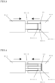
- FIG. 2 is a cross-sectional view illustrating a convex part 3211 and a concave part 3221 of the split type take-up roller 32 according to embodiment 1 of the present invention.
- a column-shaped convex part protrudes from a dividing surface of the first take-up roller 321 of the take-up roller 32 toward the second take-up roller 322. That is, the first take-up roller 321 has the convex part 3211 that protrudes toward the second take-up roller 322.
- a first facing part 32111 is disposed on an end of the column-shaped convex part 3211 at the side of the second take-up roller 322.
- a second facing part 32211 disposed on a bottom end of the concave part of the second take-up roller 322 faces the first facing part 32111.
- the flat surface of the first facing part 32111 which is located at the side of the second facing part, faces the flat surface of the second facing part 32211, which is located at the side of the first facing part.
- a disc-shaped permanent magnet is provided on the second facing part 32211 as a magnet 33.
- This gap may be larger depending on the strength of the magnet, however, it is preferable to have a gap of at least 0.5 mm for the purpose of preventing the contact with the convex part 3211.
- the permanent magnet 33 generates force to attract the first facing part 32111 by magnetic force.
- the strength of the magnetic force of the permanent magnet 33 is set to be necessary and sufficient to negate the centrifugal force that separates the first take-up roller 321 and the second take-up roller 322 when the circular knitting machine 1 is in operation.
- the second take-up roller 322 has the concave part 3221 that is a recess having a shape for housing the convex part 3211 so that the convex part 3211 is firmly engaged with the concave part 3221.
- this embodiment When this embodiment is applied to a type of unit in which the leading end of the knitted fabric is sandwiched between the first take-up roller 321 and the second take-up roller 322 so that the knitted fabric is rolled up on a take-up roll by rotating the take-up roller 32, the knitting machine is rotated to some extent that knitted fabric is knitted down a little in the state in which the take-up roller 32 is not divided before the knitting machine is actually started to knit.
- the first take-up roller 321 and the second take-up roller 322 are separated from each other to make a gap within the range that the end of the convex part is not out of the concave part to exceed the position of the dividing cross section of the take-up roller 32, so that the leading end of knitted fabric is inserted between the first take-up roller 321 and the second take-up roller 322. Then, the convex part 3211 is completely inserted into the concave part 3221.
- the knitted fabric can be sandwiched between the first take-up roller 321 and the second take-up roller 322 without being inserted into the concave part 3221.
- the position where the knitted fabric is sandwiched is different from the position where the first take-up roller 321 and the second take-up roller 322 are attracted to each other by the magnetic force.
- the knitted fabric can be sandwiched without preventing the engagement of the first take-up roller 321 with the second take-up roller 322 due to the interposition of the knitted fabric.
- auto-doffing i.e. performing automatically unloading and discharge of a roll of knitted fabric from a machine to the outside without manual work so as to start a next knitting.
- FIG. 3 is a cross-sectional view illustrating the convex part 3211 and the concave part 3221 of the split type take-up roller 32 according to embodiment 2 of the present invention.
- the convex part 3211 has a shape of a quadrangular prism
- the first facing part 32111 is a side surface of the end part of the quadrangular prism at the side of the second roller 322.
- the second facing part 32211 which faces the first facing part 32111, surrounds the first facing part 32111.
- a ring-shaped permanent magnet is provided so as to be an inner surface of the second facing part 32211.
- the end of the convex part 3211 is not likely to collide with the permanent magnet.
- FIG. 4 is a cross-sectional view illustrating the convex part 3211 and the concave part 3221 of the split type take-up roller 32 according to embodiment 3 of the present invention.
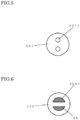
- FIG. 5 is a diagram of the first take-up roller 321 according to embodiment 3 of the present invention, which is viewed from the second take-up roller 322 side.
- FIG. 6 is a diagram of the second take-up roller 322 according to embodiment 3 of the present invention, which is viewed from the first take-up roller 321 side.
- two column-shaped convex parts 3211 are provided on the dividing surface of the first take-up roller 321 at regular intervals from the center rotational axis of the take-up roller 32.
- the first facing part 32111 includes a surface of the column-shaped convex part 3211 at the side of the second take-up roller 322.
- the second facing part 32211 includes a surface that faces the surfaces of the column-shaped convex parts 3211 at the side of the second take-up roller 322.
- the concave part 3221 has columnar holes each having an inner circumferential surface that comes into contact with the corresponding outer circumferential surface of the two column-shaped convex parts 3211.
- a wall is provided on the center of the hole so as to extend between the two column-shaped convex parts 3211.
- the wall comes into contact with the two column-shaped convex parts 3211.
- the bottom part of this wall is opened, and a disc-shaped permanent magnet is provided on the second facing part 32211 through the opened bottom part of the wall. That is, the disc-shaped permanent magnet covers the surface that faces the surfaces of the two column-shaped convex parts 3211 at the side of the second take-up roller 322. Therefore in this embodiment, the convex part is engaged with and thus positioned relative to the concave part in the rotating direction of the take-up roller 32. In this way, it is possible to prevent deviation of the first take-up roller 321 and the second take-up roller 322 from each other in the rotating direction due to the force caused by rotation of the take-up roller 32.
- the take-up roller 32 is rotated by the motive power caused by the motor in the above embodiments, however, the take-up roller 32 may be used to other types of take-up units, which include a friction type take-up unit in which a friction roller is rotated in place of the take-up roller 32 and this friction roller comes into contact with the knitted fabric rolled up on the take-up roller 32 so as to rotate, by rotational friction, the take-up roller 32 with the knitted fabric being rolled up thereon.
- a friction type take-up unit in which a friction roller is rotated in place of the take-up roller 32 and this friction roller comes into contact with the knitted fabric rolled up on the take-up roller 32 so as to rotate, by rotational friction, the take-up roller 32 with the knitted fabric being rolled up thereon.
- the take-up roller and the convex part 3211 are not needed to have a columnar shape. They may have any other shapes such as a cylinder, a sphere, a pillar, a cone and a frustum.
- the convex part 3211 is not necessarily required, and the dividing surface may be a simple vertical cross-section or the like.
- the dividing surface between the first take-up roller 321 and the second take-up roller 322 is not limited to be the vertical cross-section. It may have any other shape such as an inclined cross-section and a wavy cross-section provided that the first take-up roller 321 and the second take-up roller 322 are engaged with each other. Also, the whole dividing surface is not required to serve as an engaging surface.
- the magnet 33 is not necessarily required to be a permanent magnet. It may be, for example, an electromagnet.
- the kind of the magnet is not particularly limited, which may include, for example, ferrite and neodymium.
- the magnet may have any shape, which includes many shapes such as a rectangular ring shape with respect to the quadrangular prism.
- the outer circumferential surface of the convex part 3211 and the inner circumferential surface of the concave part 3221 may be made of a slippery material, or may have a gap therebetween. Any member may be interposed between the convex part 3211 and the concave part 3221.
- the permanent magnet may be embedded in the bottom surface of the concave part 3221. Any material may be used for the respective members, provided that parts on which the magnet acts are made of materials attracted to the magnet (such as iron, nickel and stainless). Any other configurations similar to the above embodiments are also embraced in the scope of the present invention.
Landscapes
- Physics & Mathematics (AREA)
- General Physics & Mathematics (AREA)
- Engineering & Computer Science (AREA)
- Textile Engineering (AREA)
- Knitting Machines (AREA)
Applications Claiming Priority (1)
| Application Number | Priority Date | Filing Date | Title |
|---|---|---|---|
| JP2022003026U JP3239963U (ja) | 2022-09-12 | 2022-09-12 | 丸編機用巻取装置の分割型巻取ローラ |
Publications (2)
| Publication Number | Publication Date |
|---|---|
| EP4335959A1 true EP4335959A1 (de) | 2024-03-13 |
| EP4335959B1 EP4335959B1 (de) | 2024-09-04 |
Family
ID=84227516
Family Applications (1)
| Application Number | Title | Priority Date | Filing Date |
|---|---|---|---|
| EP23196237.4A Active EP4335959B1 (de) | 2022-09-12 | 2023-09-08 | Geteilte aufnahmerolle für eine aufnahmeeinheit für eine rundstrickmaschine |
Country Status (3)
| Country | Link |
|---|---|
| EP (1) | EP4335959B1 (de) |
| JP (1) | JP3239963U (de) |
| TW (1) | TW202419700A (de) |
Citations (8)
| Publication number | Priority date | Publication date | Assignee | Title |
|---|---|---|---|---|
| US4765157A (en) * | 1986-08-23 | 1988-08-23 | Gunze Limited | Method and apparatus for rolling up fabric for circular knitting machine |
| JPH0143416B2 (de) | 1980-10-27 | 1989-09-20 | Kogyo Gijutsuin | |
| EP0351511A1 (de) * | 1988-07-21 | 1990-01-24 | H. Stoll GmbH & Co. | Abzugsvorrichtung für Flachstrickmaschinen |
| EP0493955A1 (de) * | 1990-12-27 | 1992-07-08 | Nagata Seiki Kabushiki Kaisha | Vorrichtung zum Aufwickeln und Abführen von gestricktem Stoff für eine Strickmaschine |
| JP2011011897A (ja) * | 2009-07-06 | 2011-01-20 | Hakuryu Kikaisho Kofun Yugenkoshi | 布巻取り機の巻取りロッド構造 |
| JP2011219906A (ja) * | 2010-04-14 | 2011-11-04 | Gunze Ltd | 生地の巻取装置及び丸編機 |
| CN109607325A (zh) * | 2018-12-26 | 2019-04-12 | 孙超 | 一种周身均匀的易调节纱筒 |
| JP2022003026A (ja) | 2020-06-23 | 2022-01-11 | 竜則 池本 | 治療薬およびプラセボ |
-
2022
- 2022-09-12 JP JP2022003026U patent/JP3239963U/ja active Active
-
2023
- 2023-08-31 TW TW112133097A patent/TW202419700A/zh unknown
- 2023-09-08 EP EP23196237.4A patent/EP4335959B1/de active Active
Patent Citations (9)
| Publication number | Priority date | Publication date | Assignee | Title |
|---|---|---|---|---|
| JPH0143416B2 (de) | 1980-10-27 | 1989-09-20 | Kogyo Gijutsuin | |
| US4765157A (en) * | 1986-08-23 | 1988-08-23 | Gunze Limited | Method and apparatus for rolling up fabric for circular knitting machine |
| JPH026862B2 (de) | 1986-08-23 | 1990-02-14 | Gunze Kk | |
| EP0351511A1 (de) * | 1988-07-21 | 1990-01-24 | H. Stoll GmbH & Co. | Abzugsvorrichtung für Flachstrickmaschinen |
| EP0493955A1 (de) * | 1990-12-27 | 1992-07-08 | Nagata Seiki Kabushiki Kaisha | Vorrichtung zum Aufwickeln und Abführen von gestricktem Stoff für eine Strickmaschine |
| JP2011011897A (ja) * | 2009-07-06 | 2011-01-20 | Hakuryu Kikaisho Kofun Yugenkoshi | 布巻取り機の巻取りロッド構造 |
| JP2011219906A (ja) * | 2010-04-14 | 2011-11-04 | Gunze Ltd | 生地の巻取装置及び丸編機 |
| CN109607325A (zh) * | 2018-12-26 | 2019-04-12 | 孙超 | 一种周身均匀的易调节纱筒 |
| JP2022003026A (ja) | 2020-06-23 | 2022-01-11 | 竜則 池本 | 治療薬およびプラセボ |
Also Published As
| Publication number | Publication date |
|---|---|
| TW202419700A (zh) | 2024-05-16 |
| JP3239963U (ja) | 2022-11-28 |
| EP4335959B1 (de) | 2024-09-04 |
Similar Documents
| Publication | Publication Date | Title |
|---|---|---|
| KR101727822B1 (ko) | 로터 구조 | |
| US4978237A (en) | Cage structure of roller bearing | |
| EP4335959B1 (de) | Geteilte aufnahmerolle für eine aufnahmeeinheit für eine rundstrickmaschine | |
| CN117682391A (zh) | 分割型卷取辊 | |
| EP2752594B1 (de) | Elektromagnetische kupplung und verfahren zur fertigung einer armatur für eine elektromagnetische kupplung | |
| JP6648693B2 (ja) | 軸受装置の製造方法 | |
| JP2013029144A (ja) | アンギュラ玉軸受用樹脂保持器 | |
| EP2042756B1 (de) | Käfig, Herstellungsverfahren für den Käfig, Druckrollenlager, das mit dem Käfig ausgestattet ist | |
| EP0709588A2 (de) | Konisches tiefgezogenes Topfnadellager | |
| US9611890B2 (en) | Thrust bearing | |
| JP2014062572A (ja) | テーパスナップリング | |
| EP2123925A1 (de) | Druckrollenlager | |
| JPH09177770A (ja) | ころ軸受 | |
| JP2003336645A (ja) | スラスト円筒ころ軸受 | |
| CN110486378B (zh) | 推力滚子轴承 | |
| JP6392083B2 (ja) | テープカートリッジ | |
| JP2017180546A (ja) | スラスト玉軸受用銅合金製保持器及びスラスト玉軸受用銅合金製保持器を備えたスラスト玉軸受 | |
| US20120275740A1 (en) | Rolling-element bearing, and method and apparatus for manufacturing rolling-element bearing | |
| CN221921700U (zh) | 滚子轴承用保持器、带保持器滚子以及滚子轴承 | |
| JPH11336798A (ja) | 一方向クラッチの保持器の製造方法 | |
| WO2023204161A1 (ja) | ころ軸受 | |
| EP2860414A1 (de) | Kegelrollenlager | |
| JP2010116970A (ja) | スラスト軸受用保持器およびスラスト軸受 | |
| EP3770453B1 (de) | Wälzlagerkäfig | |
| JP2023159859A (ja) | ころ軸受 |
Legal Events
| Date | Code | Title | Description |
|---|---|---|---|
| PUAI | Public reference made under article 153(3) epc to a published international application that has entered the european phase |
Free format text: ORIGINAL CODE: 0009012 |
|
| STAA | Information on the status of an ep patent application or granted ep patent |
Free format text: STATUS: THE APPLICATION HAS BEEN PUBLISHED |
|
| AK | Designated contracting states |
Kind code of ref document: A1 Designated state(s): AL AT BE BG CH CY CZ DE DK EE ES FI FR GB GR HR HU IE IS IT LI LT LU LV MC ME MK MT NL NO PL PT RO RS SE SI SK SM TR |
|
| STAA | Information on the status of an ep patent application or granted ep patent |
Free format text: STATUS: REQUEST FOR EXAMINATION WAS MADE |
|
| GRAP | Despatch of communication of intention to grant a patent |
Free format text: ORIGINAL CODE: EPIDOSNIGR1 |
|
| STAA | Information on the status of an ep patent application or granted ep patent |
Free format text: STATUS: GRANT OF PATENT IS INTENDED |
|
| 17P | Request for examination filed |
Effective date: 20240326 |
|
| RBV | Designated contracting states (corrected) |
Designated state(s): AL AT BE BG CH CY CZ DE DK EE ES FI FR GB GR HR HU IE IS IT LI LT LU LV MC ME MK MT NL NO PL PT RO RS SE SI SK SM TR |
|
| INTG | Intention to grant announced |
Effective date: 20240426 |
|
| RIC1 | Information provided on ipc code assigned before grant |
Ipc: D04B 15/88 20060101AFI20240412BHEP |
|
| GRAS | Grant fee paid |
Free format text: ORIGINAL CODE: EPIDOSNIGR3 |
|
| GRAA | (expected) grant |
Free format text: ORIGINAL CODE: 0009210 |
|
| STAA | Information on the status of an ep patent application or granted ep patent |
Free format text: STATUS: THE PATENT HAS BEEN GRANTED |
|
| AK | Designated contracting states |
Kind code of ref document: B1 Designated state(s): AL AT BE BG CH CY CZ DE DK EE ES FI FR GB GR HR HU IE IS IT LI LT LU LV MC ME MK MT NL NO PL PT RO RS SE SI SK SM TR |
|
| REG | Reference to a national code |
Ref country code: GB Ref legal event code: FG4D |
|
| P01 | Opt-out of the competence of the unified patent court (upc) registered |
Free format text: CASE NUMBER: APP_44981/2024 Effective date: 20240802 |
|
| REG | Reference to a national code |
Ref country code: CH Ref legal event code: EP |
|
| REG | Reference to a national code |
Ref country code: IE Ref legal event code: FG4D |
|
| REG | Reference to a national code |
Ref country code: DE Ref legal event code: R096 Ref document number: 602023000503 Country of ref document: DE |
|
| REG | Reference to a national code |
Ref country code: LT Ref legal event code: MG9D |
|
| REG | Reference to a national code |
Ref country code: NL Ref legal event code: MP Effective date: 20240904 |
|
| PG25 | Lapsed in a contracting state [announced via postgrant information from national office to epo] |
Ref country code: NO Free format text: LAPSE BECAUSE OF FAILURE TO SUBMIT A TRANSLATION OF THE DESCRIPTION OR TO PAY THE FEE WITHIN THE PRESCRIBED TIME-LIMIT Effective date: 20241204 |
|
| PG25 | Lapsed in a contracting state [announced via postgrant information from national office to epo] |
Ref country code: GR Free format text: LAPSE BECAUSE OF FAILURE TO SUBMIT A TRANSLATION OF THE DESCRIPTION OR TO PAY THE FEE WITHIN THE PRESCRIBED TIME-LIMIT Effective date: 20241205 Ref country code: FI Free format text: LAPSE BECAUSE OF FAILURE TO SUBMIT A TRANSLATION OF THE DESCRIPTION OR TO PAY THE FEE WITHIN THE PRESCRIBED TIME-LIMIT Effective date: 20240904 |
|
| PG25 | Lapsed in a contracting state [announced via postgrant information from national office to epo] |
Ref country code: BG Free format text: LAPSE BECAUSE OF FAILURE TO SUBMIT A TRANSLATION OF THE DESCRIPTION OR TO PAY THE FEE WITHIN THE PRESCRIBED TIME-LIMIT Effective date: 20240904 |
|
| PG25 | Lapsed in a contracting state [announced via postgrant information from national office to epo] |
Ref country code: LV Free format text: LAPSE BECAUSE OF FAILURE TO SUBMIT A TRANSLATION OF THE DESCRIPTION OR TO PAY THE FEE WITHIN THE PRESCRIBED TIME-LIMIT Effective date: 20240904 |
|
| PG25 | Lapsed in a contracting state [announced via postgrant information from national office to epo] |
Ref country code: HR Free format text: LAPSE BECAUSE OF FAILURE TO SUBMIT A TRANSLATION OF THE DESCRIPTION OR TO PAY THE FEE WITHIN THE PRESCRIBED TIME-LIMIT Effective date: 20240904 |
|
| PG25 | Lapsed in a contracting state [announced via postgrant information from national office to epo] |
Ref country code: RS Free format text: LAPSE BECAUSE OF FAILURE TO SUBMIT A TRANSLATION OF THE DESCRIPTION OR TO PAY THE FEE WITHIN THE PRESCRIBED TIME-LIMIT Effective date: 20241204 Ref country code: ES Free format text: LAPSE BECAUSE OF FAILURE TO SUBMIT A TRANSLATION OF THE DESCRIPTION OR TO PAY THE FEE WITHIN THE PRESCRIBED TIME-LIMIT Effective date: 20240904 |
|
| PG25 | Lapsed in a contracting state [announced via postgrant information from national office to epo] |
Ref country code: RS Free format text: LAPSE BECAUSE OF FAILURE TO SUBMIT A TRANSLATION OF THE DESCRIPTION OR TO PAY THE FEE WITHIN THE PRESCRIBED TIME-LIMIT Effective date: 20241204 Ref country code: NO Free format text: LAPSE BECAUSE OF FAILURE TO SUBMIT A TRANSLATION OF THE DESCRIPTION OR TO PAY THE FEE WITHIN THE PRESCRIBED TIME-LIMIT Effective date: 20241204 Ref country code: LV Free format text: LAPSE BECAUSE OF FAILURE TO SUBMIT A TRANSLATION OF THE DESCRIPTION OR TO PAY THE FEE WITHIN THE PRESCRIBED TIME-LIMIT Effective date: 20240904 Ref country code: HR Free format text: LAPSE BECAUSE OF FAILURE TO SUBMIT A TRANSLATION OF THE DESCRIPTION OR TO PAY THE FEE WITHIN THE PRESCRIBED TIME-LIMIT Effective date: 20240904 Ref country code: GR Free format text: LAPSE BECAUSE OF FAILURE TO SUBMIT A TRANSLATION OF THE DESCRIPTION OR TO PAY THE FEE WITHIN THE PRESCRIBED TIME-LIMIT Effective date: 20241205 Ref country code: FI Free format text: LAPSE BECAUSE OF FAILURE TO SUBMIT A TRANSLATION OF THE DESCRIPTION OR TO PAY THE FEE WITHIN THE PRESCRIBED TIME-LIMIT Effective date: 20240904 Ref country code: ES Free format text: LAPSE BECAUSE OF FAILURE TO SUBMIT A TRANSLATION OF THE DESCRIPTION OR TO PAY THE FEE WITHIN THE PRESCRIBED TIME-LIMIT Effective date: 20240904 Ref country code: BG Free format text: LAPSE BECAUSE OF FAILURE TO SUBMIT A TRANSLATION OF THE DESCRIPTION OR TO PAY THE FEE WITHIN THE PRESCRIBED TIME-LIMIT Effective date: 20240904 |
|
| REG | Reference to a national code |
Ref country code: AT Ref legal event code: MK05 Ref document number: 1720482 Country of ref document: AT Kind code of ref document: T Effective date: 20240904 |
|
| PG25 | Lapsed in a contracting state [announced via postgrant information from national office to epo] |
Ref country code: NL Free format text: LAPSE BECAUSE OF FAILURE TO SUBMIT A TRANSLATION OF THE DESCRIPTION OR TO PAY THE FEE WITHIN THE PRESCRIBED TIME-LIMIT Effective date: 20240904 |
|
| PG25 | Lapsed in a contracting state [announced via postgrant information from national office to epo] |
Ref country code: PT Free format text: LAPSE BECAUSE OF FAILURE TO SUBMIT A TRANSLATION OF THE DESCRIPTION OR TO PAY THE FEE WITHIN THE PRESCRIBED TIME-LIMIT Effective date: 20250106 Ref country code: IS Free format text: LAPSE BECAUSE OF FAILURE TO SUBMIT A TRANSLATION OF THE DESCRIPTION OR TO PAY THE FEE WITHIN THE PRESCRIBED TIME-LIMIT Effective date: 20250104 |
|
| PG25 | Lapsed in a contracting state [announced via postgrant information from national office to epo] |
Ref country code: SM Free format text: LAPSE BECAUSE OF FAILURE TO SUBMIT A TRANSLATION OF THE DESCRIPTION OR TO PAY THE FEE WITHIN THE PRESCRIBED TIME-LIMIT Effective date: 20240904 Ref country code: RO Free format text: LAPSE BECAUSE OF FAILURE TO SUBMIT A TRANSLATION OF THE DESCRIPTION OR TO PAY THE FEE WITHIN THE PRESCRIBED TIME-LIMIT Effective date: 20240904 |
|
| PG25 | Lapsed in a contracting state [announced via postgrant information from national office to epo] |
Ref country code: EE Free format text: LAPSE BECAUSE OF FAILURE TO SUBMIT A TRANSLATION OF THE DESCRIPTION OR TO PAY THE FEE WITHIN THE PRESCRIBED TIME-LIMIT Effective date: 20240904 Ref country code: AT Free format text: LAPSE BECAUSE OF FAILURE TO SUBMIT A TRANSLATION OF THE DESCRIPTION OR TO PAY THE FEE WITHIN THE PRESCRIBED TIME-LIMIT Effective date: 20240904 |
|
| PG25 | Lapsed in a contracting state [announced via postgrant information from national office to epo] |
Ref country code: PL Free format text: LAPSE BECAUSE OF FAILURE TO SUBMIT A TRANSLATION OF THE DESCRIPTION OR TO PAY THE FEE WITHIN THE PRESCRIBED TIME-LIMIT Effective date: 20240904 |
|
| PG25 | Lapsed in a contracting state [announced via postgrant information from national office to epo] |
Ref country code: SK Free format text: LAPSE BECAUSE OF FAILURE TO SUBMIT A TRANSLATION OF THE DESCRIPTION OR TO PAY THE FEE WITHIN THE PRESCRIBED TIME-LIMIT Effective date: 20240904 |
|
| REG | Reference to a national code |
Ref country code: DE Ref legal event code: R097 Ref document number: 602023000503 Country of ref document: DE |
|
| PG25 | Lapsed in a contracting state [announced via postgrant information from national office to epo] |
Ref country code: MC Free format text: LAPSE BECAUSE OF FAILURE TO SUBMIT A TRANSLATION OF THE DESCRIPTION OR TO PAY THE FEE WITHIN THE PRESCRIBED TIME-LIMIT Effective date: 20240904 |
|
| PG25 | Lapsed in a contracting state [announced via postgrant information from national office to epo] |
Ref country code: DK Free format text: LAPSE BECAUSE OF FAILURE TO SUBMIT A TRANSLATION OF THE DESCRIPTION OR TO PAY THE FEE WITHIN THE PRESCRIBED TIME-LIMIT Effective date: 20240904 |
|
| PLBE | No opposition filed within time limit |
Free format text: ORIGINAL CODE: 0009261 |
|
| STAA | Information on the status of an ep patent application or granted ep patent |
Free format text: STATUS: NO OPPOSITION FILED WITHIN TIME LIMIT |
|
| 26N | No opposition filed |
Effective date: 20250605 |
|
| PG25 | Lapsed in a contracting state [announced via postgrant information from national office to epo] |
Ref country code: SE Free format text: LAPSE BECAUSE OF FAILURE TO SUBMIT A TRANSLATION OF THE DESCRIPTION OR TO PAY THE FEE WITHIN THE PRESCRIBED TIME-LIMIT Effective date: 20240904 |
|
| PGFP | Annual fee paid to national office [announced via postgrant information from national office to epo] |
Ref country code: DE Payment date: 20250808 Year of fee payment: 3 |
|
| PGFP | Annual fee paid to national office [announced via postgrant information from national office to epo] |
Ref country code: TR Payment date: 20250820 Year of fee payment: 3 |
|
| PG25 | Lapsed in a contracting state [announced via postgrant information from national office to epo] |
Ref country code: FR Free format text: LAPSE BECAUSE OF NON-PAYMENT OF DUE FEES Effective date: 20241104 |
|
| PGFP | Annual fee paid to national office [announced via postgrant information from national office to epo] |
Ref country code: CZ Payment date: 20250813 Year of fee payment: 3 |
|
| PGFP | Annual fee paid to national office [announced via postgrant information from national office to epo] |
Ref country code: IT Payment date: 20250930 Year of fee payment: 3 |