EP4335988B1 - Lamellenüberdachung - Google Patents
Lamellenüberdachung Download PDFInfo
- Publication number
- EP4335988B1 EP4335988B1 EP23192654.4A EP23192654A EP4335988B1 EP 4335988 B1 EP4335988 B1 EP 4335988B1 EP 23192654 A EP23192654 A EP 23192654A EP 4335988 B1 EP4335988 B1 EP 4335988B1
- Authority
- EP
- European Patent Office
- Prior art keywords
- hinged
- louvered
- canopy
- worm
- bar
- Prior art date
- Legal status (The legal status is an assumption and is not a legal conclusion. Google has not performed a legal analysis and makes no representation as to the accuracy of the status listed.)
- Active
Links
Images





Classifications
-
- E—FIXED CONSTRUCTIONS
- E04—BUILDING
- E04F—FINISHING WORK ON BUILDINGS, e.g. STAIRS, FLOORS
- E04F10/00—Sunshades, e.g. Florentine blinds or jalousies; Outside screens; Awnings or baldachins
- E04F10/08—Sunshades, e.g. Florentine blinds or jalousies; Outside screens; Awnings or baldachins of a plurality of similar rigid parts, e.g. slabs, lamellae
- E04F10/10—Sunshades, e.g. Florentine blinds or jalousies; Outside screens; Awnings or baldachins of a plurality of similar rigid parts, e.g. slabs, lamellae collapsible or extensible; metallic Florentine blinds; awnings with movable parts such as louvres
Definitions
- the present invention pertains to the technical field of louvered canopies, and relates to a louvered canopy.
- a louvered canopy is a type of architectural structure that provides shade or shelter from weather conditions such as wind, rain and sun and prevents injuries from falling objects. It typically comprises: a vertical column, a frame fixed to an upper end of the vertical column, a number of louver blades parallel to each other and hinged to the frame, and a transmission mechanism that drives the louver blades to open and close to realize both sun shading and adjustment of sunlight angle.
- louvered canopy is disclosed in Chinese patent [Application No.: CN201920735503.1 ], which comprises: a frame; a number of louver blades arranged on the frame, each louvered blade having a rotary shaft that is fixed to the louvered blade and rotationally connected to the frame, each rotary shaft being provided with a pivot bar that is fixed to the rotary shaft; and a linkage bar that is provided on the frame and capable of swinging, with all the pivot bars being fixed to the linkage bar.
- a swinging motion of the linkage bar can drive all the pivot bars to pivot, causing the louver blades to rotate, thereby achieving opening and closing of the louver blades.
- Manual control allows for freely control of the louver blades without being influenced by environmental factors.
- a control rod is provided inside a vertical column of the louvered canopy, a flexible shaft made of a flexible material is provided at an upper end of the control rod, a worm gearbox is disposed between the flexible shaft and a linkage rod, and a bevel gear assembly capable of driving rotation of the control rod is provided at a lower end of the control rod.
- the bevel gear assembly drives rotation of the control rod, which in turn rotates the flexible shaft; the flexible shaft further drives rotation of a worm wheel within the worm gearbox, where the worm wheel meshes with a worm gear, resulting in rotation of the worm gear; finally, the worm gear drives horizontal movement of the linkage rod.
- this design has several drawbacks: it has a long transmission stroke, and requires a substantial amount of force to operate; the flexible shaft is subject to high wear and tear, leading to fatigue damage after prolonged use and necessitating replacement, causing operational inconvenience.
- Another existing manual control structure utilizes a multi-gear-set transmission consisting of multiple sets of gear parts.
- Some objectives of embodiments of the present invention are to provide a louvered canopy with respect to the above defects in the prior art, to solve the technical problem on how to more conveniently control opening and closing of louver blades and achieve a louvered canopy with a simple structure and decreased wear and tear.
- a louvered canopy comprising: a vertical column, a frame provided at an upper end of the vertical column, louver blades hinged to the frame and capable of opening and closing, and a control structure capable of controlling opening and closing of the louver blades, wherein
- the design concept is as follows: manually rotation of the worm gear drives the worm wheel to rotate, and the rotation of the worm wheel drives the worm-driven bar, which is fixed to the worm wheel, to move along an arc path; since the second end of the worm-driven bar is hinged to the lower end of the control bar, the upper end of the control bar is hinged to the effort end, and the louver blade directional switching element is hinged to the frame, consequently, the movement of the worm-driven bar drives the control bar to swing up and down and the louver blade directional switching element to pivot around a hinge point between the louver blade directional switching element and the frame; the louver blade directional switching element has three hinge points, which are located at the effort end and the load end of the hinged lever member, as well as the second end of the fulcrum member that is distal from the hinged lever member, respectively, and these hinge points form a triangular structure, that is, the hinged lever member and the fulcrum member form an approximately T-shaped structure
- the combination arrangement of the three parts - the worm-driven bar, the control bar, and the louver blade directional switching element - enables transformation of a vertical motion component of the worm wheel's rotational movement into a horizontal motion component of the load end, and also achieves structural simplification compared to the aforementioned complex multi-gear-set transmission.
- the worm-driven bar, the control bar, and the louver blade directional switching element are interconnected through hinged connections, eliminating the backlash issues associated with traditional multi-gear systems, therefore, compared to the prior art, this design offers higher overall precision, reduced wear and tear, and a stable transmission structure, moreover, the various parts are less prone to fatigue damage, ensuring a long service life even with prolonged use.
- the hinged lever member tends to shift to one side, that is, when the load end and the effort end are located on the left and right sides of the hinge point between the fulcrum member and the frame, respectively, the shift tendency of the hinged lever member will be amplified at the load end.
- a weight of the louver blades and a weight of several auxiliary mechanisms connected to the load end through the linkage transmission mechanism assist the hinged lever member in driving the louver blades, thus reducing to some extent a force that a user needs to indirectly apply to the hinged lever member for driving opening and closing of the louver blades, making operation more convenient.
- a distance from the effort end to the supporting center i.e., the hinge point between the louver blade directional switching element and the frame
- a distance from the load end to the supporting center it allows for a more effortless operation by using the principle of a lever.
- a reinforcing member is provided between the load end and the fulcrum member, two ends of the reinforcing member being fixed to the load end and the fulcrum member, respectively.
- the three parts - the reinforcing member provided between the load end and the fulcrum member, the load end, and the fulcrum member - form a triangular structure, which can effectively support the load end, transfer the applied force from the load end to the fulcrum member, limit deformation of the load end, enhance structural stability, and ensure precision.
- the reinforcing member has one end fixed to a tip portion of the load end and the other end fixed to the second end of the fulcrum member that is distal from the hinged lever member.
- a connecting bar capable of bringing the louver blades to rotate is hinged by a first pivot pin at a connection point between the reinforcing member and the load end, while a connection point between the reinforcing member and the fulcrum member is hinged to the frame by a second pivot pin.
- the upper end of the control bar is provided with two hinge plates arranged vertically and parallel to each other, allowing the effort end to be positioned between the two hinge plates and hinged to the hinge plates, the effort end having a gradually increasing width in a direction towards the fulcrum member. This gradual increase in width of the effort end in the direction towards the fulcrum member enhances the structural strength of the effort end. Meanwhile, the effort end, positioned between the two hinge plates, is able to rotate around its hinge point where it is hinged to the hinge plates. If the width of the effort end is too long, it may collide with the upper end of the control bar during movement.
- a width of a tip portion of the effort end, distal from the fulcrum member is designed to be relatively small, which ensures that there is no collision between the effort end and the upper end of the control bar, and allows the hinge plates to have an appropriate vertical length without the need for excessive elongation to prevent collision between the effort end and the control bar.
- the fulcrum member, the hinged lever member, and the reinforcing member are integrally formed by molding, and a maximum width of the effort end is less than half a width of the louver blade directional switching element at the position of the fulcrum member.
- integral forming by molding, the same material is used for all parts.
- the width of the louver blade directional switching element at the position of the fulcrum member is sufficiently large when designed to meet a minimum structural strength requirement, ensuring a sufficiently large rotation radius for the entire louver blade directional switching element during pivoting, allowing for an amplified horizontal travel distance of the louver blades and reducing an amount of movement required in manual operation.
- the manual drive assembly is fixed to a middle part of the vertical column, the worm gear is arranged horizontally and has one end penetrating through the vertical column, allowing a handle to be fixed to the worm gear.
- This arrangement enables a user to manually rotates the handle, which in turn drives the worm wheel.
- the worm wheel then drives the worm gear. Consequently, the worm gear drives the worm-driven bar, causing the louver blade directional switching element to pivot.
- the utilization of the worm-wheel-and-worm-gear mechanism is simple and facilitates the opening and closing of the louver blades.
- the present louvered canopy has the following advantages:
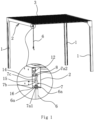
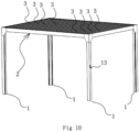
- a louvered canopy comprises: a vertical column 1, and a frame 2 provided at a top end of the vertical column 1. A total of four vertical columns 1 are provided and disposed vertically.
- the frame 2 is in a rectangular shape and formed by enclosing four elongated frame beams 2a.
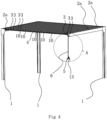
- a plurality of parallel louver blades 3 are rotatably connected to the frame 2. One end of each of the louver blades 3 extends into one of the frame beams 2a and is provided with a crank arm 10 fixed thereto, while the other end of each of the louver blades 3 extends into an opposite frame beam 2a.
- the cranks arm 10 are hinged together to a linkage bar 4, which is horizontally provided inside the frame beam 2a.
- a linkage bar 4 swings, all the cranks arms 10 follow the linkage bar to rotate, thereby realizing opening or closing of the louver blades 3.
- one end of one of the louver blades 3 is fixed with a rotary shaft 11, and the rotary shaft 11 is fixed with an actuation bar 12 which is parallel to and in the same orientation as the crank arm 10.
- the actuation bar 12 is used to input power to rotate the rotary shaft 11, thus using the one louver blade 3 to cause a row of louver blades 3 to swing.
- the louvered canopy further comprises a control structure for controlling opening and closing of the louver blades 3.
- the control structure comprises a control bar 6 and a manual drive assembly 5.
- the control bar 6 is vertically provided inside one of the vertical columns 1 and is capable of swinging inside the vertical column 1.
- the manual drive assembly 5 is located at a middle part of the vertical column 1, a lower end of the control bar 6 is hinged to the manual drive assembly 5, the manual drive assembly 5 is used to input power to swing the control bar 6, an upper end of the control bar 6 is connected to the linkage bar 4 through a transmission mechanism, and the control bar 6 can drive the linkage bar 4 to swing when it swings.
- the manual driving assembly 5 comprises a worm gearbox 5c, as well as a worm wheel 5b and a worm gear 5a, both located within the worm gearbox 5c.
- the worm gear 5a is rotationally mounted on the worm gearbox 5c and horizontally arranged, and extends out of the vertical column 1 at one end, where a handle 13 is fixed to the worm gear 5a.
- the worm gear 5a is rotationally connected to the vertical column 1.
- the worm wheel 5b is also rotationally mounted on the worm gearbox 5c and meshes with the worm gear 5a.
- the lower end of the control bar 6 is hinged to a worm-driven bar 9, with one end of the worm-driven bar 9 being fixed to the worm wheel 5b.
- the rotation of the worm wheel 5b causes the entire worm-driven bar 9 to move along an arc path.
- a user inputs power to cause rotation of the worm gear 5a, which in turn rotates the worm wheel 5b and drives the worm-driven bar 9, and then the worm-driven bar 9 brings the control bar 6 to swing around its hinge point that is connected to the worm-driven bar 9.
- the control structure further comprises a louver blade directional switching element 7, which is hinged to the upper end of control bar 6.
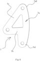
- the louver blade directional switching element 7 comprises: an elongated hinged lever member 7a, and an elongated fulcrum member 7b fixed to a middle part of the hinged lever member 7a.
- the hinged lever member 7a has two ends, namely, an effort end 7a1 and a load end 7a2.
- the load end 7a2 is hinged to a connecting bar 8, which is hinged to an actuation bar 12.
- a reinforcing member 7c is provided between the load end 7a2 and the fulcrum member 7b, with two ends of the reinforcing member 7c being fixed to the load end 7a2 and one end of the fulcrum member 7b that is distal from the hinged lever member 7a, respectively, so that the three parts - the fulcrum member 7b, the load end 7a2, and the reinforcing member 7c - form a triangular structure, which ensures structural stability.
- an intersection of the reinforcing member 7c and the load end 7a2 is hinged to the connecting bar 8 via a first pivot pin 14, while an intersection of the reinforcing member 7c and the fulcrum member 7b is hinged to the frame 2 via a second pivot pin 15.
- the upper end of control bar 6 is provided with two parallel and vertically provided hinge plates 6a.
- the effort end 7a1 is located between the two hinge plates 6a and is hinged to them via a third pivot pin 15.
- a width of the effort end 7a1 gradually increases towards the direction of the fulcrum member 7b until it reaches the fulcrum member 7b, with a maximum width of the effort end 7a1 being less than half a width of the louver blade directional switching element 7 at the position of the fulcrum member 7b.
- the width increase of the effort end 7a1 enhances its structural strength.
- the hinged lever member 7a, the reinforcing member 7c, and the fulcrum member 7b are all integrally formed by molding with aluminum.
- the effort end 7a1 is always located below the load end 7a2.
- the hinged lever member 7a tends to shift to one side, that is, when the load end 7a2 and the effort end 7a1 are located on the left and right sides of the hinge point between the fulcrum member 7b and the frame 2, respectively, the shift tendency of the hinged lever member 7a will be amplified at the load end 7a2.
- a weight of the louver blades 3 and a weight of several auxiliary mechanisms connected to the load end 7a2 through the linkage transmission mechanism assist the hinged lever member 7a in driving the louver blades 3, thus reducing to some extent a force that a user needs to indirectly apply to the hinged lever member 7a for driving opening and closing of the louver blades 3, making operation more convenient.
Landscapes
- Engineering & Computer Science (AREA)
- Architecture (AREA)
- Civil Engineering (AREA)
- Structural Engineering (AREA)
- Specific Sealing Or Ventilating Devices For Doors And Windows (AREA)
Claims (7)
- Eine Lamellenüberdachung, umfassend:eine vertikale Säule (1), einen Rahmen (2), der an einem oberen Ende der vertikalen Säule (1) angebracht ist, Lamellen (3), die an dem Rahmen (2) angelenkt sind und sich öffnen und schließen können, und eine Steuerstruktur, die das Öffnen und Schließen der Lamellen (3) steuern kann,die Steuerstruktur umfasst ein Lamellen-Richtungsschaltelement (7) und eine Steuerstange (6), wobei die Steuerstange (6) vertikal angebracht und in die vertikale Säule (1) eingesetzt ist, die Steuerstruktur umfasst ferner eine manuelle Antriebsbaugruppe (5), die an der vertikalen Säule (1) angebracht ist, die manuelle Antriebsbaugruppe (5) umfasst ein Schneckengetriebe (5a), ein Schneckenrad (5b) und eine Schneckenantriebsstange (9), wobei das Schneckengetriebe (5a) drehbar an der vertikalen Säule (1) angebracht ist und mit dem Schneckenrad (5b) in Eingriff steht, dadurch gekennzeichnet, dass die Steuerstange (6) in der Lage ist, auf- und abzuschwingen,das Lamellen-Richtungsschaltelement (7) umfasst ein angelenktes Hebelelement (7a) und ein Drehachsenelement (7b), wobei ein erstes Ende des Drehachsenelements (7b) an einem mittleren Teil des angelenkten Hebelelements (7a) befestigt ist, während ein zweites Ende des Drehachsenelements (7b) an dem Rahmen (2) angelenkt ist,das angelenkte Hebelelement (7a) weist ein Antriebsende (7a1) und ein Belastungsende (7a2) auf, wobei sich das Antriebsende (7a1) unter dem Belastungsende (7a2) befindet und sich das Antriebsende (7a1) und das Belastungsende (7a2) jeweils auf gegenüberliegenden Seiten des Drehachsenelements (7b) befinden,das Antriebsende (7a1) ist an einem oberen Ende der Steuerstange (6) angelenkt,das Belastungsende (7a2) ist mit den Lamellen über einen Gestänge-Übertragungsmechanismus verbunden,die manuelle Antriebsbaugruppe (5) ist an der vertikalen Säule (1) angebracht und in der Lage, die Steuerstange (6) zum Auf- und Abschwingen anzutreiben, ein erstes Ende der über das Schneckengetriebe angetriebenen Stange (9) ist an dem Schneckenrad (5b) befestigt, während ein zweites Ende der über das Schneckengetriebe angetriebenen Stange (9) an einem unteren Ende der Steuerstange (6) angelenkt ist.
- Lamellenüberdachung nach Anspruch 1, wobei ein Verstärkungselement (7c) zwischen dem Belastungsende (7a2) und dem Drehachsenelement (7b) angebracht ist, wobei zwei Enden des Verstärkungselements (7c) an dem Belastungsende (7a2) bzw. dem Drehachsenelement (7b) befestigt sind.
- Lamellenüberdachung nach Anspruch 2, wobei das Verstärkungselement (7c) an dem zweiten Ende des Drehachsenelements (7b) befestigt ist, das sich distal zum angelenkten Hebelelement (7a) befindet.
- Lamellenüberdachung nach Anspruch 3, wobei eine Verbindungsstange (8), die in der Lage ist, die Lamellen (3) in Drehung zu versetzen, über einen ersten Drehzapfen (14) an einem Verbindungspunkt zwischen dem Verstärkungselement (7c) und dem Belastungsende (7a2) angelenkt ist, während ein Verbindungspunkt zwischen dem Verstärkungselement (7c) und dem Drehachsenelement (7b) über einen zweiten Drehzapfen (15) an dem Rahmen (2) angelenkt ist.
- Lamellenüberdachung nach Anspruch 3, wobei das obere Ende der Steuerstange (6) mit zwei Scharnierplatten (6a) versehen ist, die vertikal und parallel zueinander angeordnet sind, so dass das Antriebsende (7a1) zwischen den zwei Scharnierplatten (6a) positioniert und an den Scharnierplatten (6a) angelenkt werden kann, wobei das Antriebsende (7a1) eine allmählich zunehmende Breite in einer Richtung zu dem Drehachsenelement (7b) aufweist.
- Lamellenüberdachung nach Anspruch 5, wobei das Drehachsenelement (7b), das angelenkte Hebelelement (7a) und das Verstärkungselement (7c) aus einem Stück geformt sind und eine maximale Breite des Antriebsendes (7a1) weniger als eine halbe Breite des Lamellen-Richtungsschaltelements (7) an der Position des Drehachsenelements (7b) beträgt.
- Lamellenüberdachung nach Anspruch 1 oder 2 oder 3 oder 4, wobei die manuelle Antriebsbaugruppe (5) an einem mittleren Teil der vertikalen Säule (1) befestigt ist, das Schneckenrad (5a) horizontal angeordnet ist und mit einem Ende die vertikale Säule (1) durchdringt, so dass ein Griff (13) am Schneckenrad (5a) befestigt werden kann.
Applications Claiming Priority (1)
| Application Number | Priority Date | Filing Date | Title |
|---|---|---|---|
| CN202222269677.8U CN218714478U (zh) | 2022-08-24 | 2022-08-24 | 一种百叶棚的控制结构 |
Publications (3)
| Publication Number | Publication Date |
|---|---|
| EP4335988A1 EP4335988A1 (de) | 2024-03-13 |
| EP4335988C0 EP4335988C0 (de) | 2025-01-15 |
| EP4335988B1 true EP4335988B1 (de) | 2025-01-15 |
Family
ID=85631538
Family Applications (1)
| Application Number | Title | Priority Date | Filing Date |
|---|---|---|---|
| EP23192654.4A Active EP4335988B1 (de) | 2022-08-24 | 2023-08-22 | Lamellenüberdachung |
Country Status (5)
| Country | Link |
|---|---|
| US (1) | US12448776B2 (de) |
| EP (1) | EP4335988B1 (de) |
| CN (1) | CN218714478U (de) |
| CA (1) | CA3209904A1 (de) |
| ES (1) | ES3012408T3 (de) |
Families Citing this family (5)
| Publication number | Priority date | Publication date | Assignee | Title |
|---|---|---|---|---|
| US12195976B2 (en) * | 2023-04-18 | 2025-01-14 | Zhejiang Jiansheng Leisure Products Co., Ltd | Outdoor louvered tent |
| US12546115B2 (en) * | 2023-11-21 | 2026-02-10 | Jiangxi Chuangba Intelligence Household Co., Ltd. | Louvered shed |
| USD1116159S1 (en) * | 2024-03-18 | 2026-03-03 | Zhejiang Dosoly Mechanical & Electrical Technology Co., Ltd | Carport |
| CN223724250U (zh) * | 2025-01-08 | 2025-12-26 | 广东森蓝建材科技有限公司 | 一种太阳能户外遮阳棚 |
| USD1088275S1 (en) * | 2025-02-20 | 2025-08-12 | Zhejiang pioneer leisure products co., ltd | Gazebo canopy |
Family Cites Families (16)
| Publication number | Priority date | Publication date | Assignee | Title |
|---|---|---|---|---|
| US6421966B1 (en) | 2000-04-28 | 2002-07-23 | Kawneer Company Inc. | Sunshade for building exteriors |
| US20040031233A1 (en) | 2002-08-16 | 2004-02-19 | Cope Timothy Wayne | Qwik pin |
| US7568319B2 (en) | 2005-06-29 | 2009-08-04 | Fairbairn Patrick A | Louver style roof system and method |
| FR2947845B1 (fr) | 2009-07-09 | 2011-10-07 | Biossun | Installation a lames orientables formant un toit de protection s'ouvrant et se fermant |
| US20130082115A1 (en) | 2011-10-03 | 2013-04-04 | Matthew Ryan May | Remote Controlled Vent Register |
| US9422715B1 (en) | 2012-05-01 | 2016-08-23 | C. Scott Selzer | Louvered roof apparatus and control system |
| US9644374B2 (en) | 2014-12-20 | 2017-05-09 | Michael Ivic | Pergola cover |
| CN205617895U (zh) | 2016-05-21 | 2016-10-05 | 浙江永强集团股份有限公司 | 一种帐篷的百叶窗顶棚结构 |
| US11149438B2 (en) | 2018-04-30 | 2021-10-19 | Sundance Louvered Roofs Llc | Louvered panel assembly |
| US10988936B2 (en) | 2019-05-06 | 2021-04-27 | Johanes SOETANTO | Pergola louver tilt system |
| US11401713B2 (en) | 2020-05-19 | 2022-08-02 | Clark Wacman Designs | Linear drive louvered roof apparatus and control system |
| CN111946104A (zh) * | 2020-08-13 | 2020-11-17 | 浙江临亚股份有限公司 | 一种可360°双向开合的多叶片顶遮阳篷 |
| US11686101B2 (en) | 2021-01-27 | 2023-06-27 | Yu Yang Industrial Co., Ltd. | Electric awning structure |
| CN216043002U (zh) * | 2021-04-09 | 2022-03-15 | 临海市美阳伞业有限公司 | 一种具有隐藏式百叶开合驱动结构的百叶篷 |
| DE212021000244U1 (de) * | 2021-04-09 | 2022-08-25 | Linhai Meiyang Parasol Industry Co., Ltd. | Lamellenvordach mit einer versteckten Antriebsstruktur zum Öffnen und Schließen von Lamellen |
| US12195976B2 (en) * | 2023-04-18 | 2025-01-14 | Zhejiang Jiansheng Leisure Products Co., Ltd | Outdoor louvered tent |
-
2022
- 2022-08-24 CN CN202222269677.8U patent/CN218714478U/zh active Active
-
2023
- 2023-08-22 CA CA3209904A patent/CA3209904A1/en active Pending
- 2023-08-22 ES ES23192654T patent/ES3012408T3/es active Active
- 2023-08-22 EP EP23192654.4A patent/EP4335988B1/de active Active
- 2023-08-22 US US18/236,905 patent/US12448776B2/en active Active
Also Published As
| Publication number | Publication date |
|---|---|
| EP4335988C0 (de) | 2025-01-15 |
| US20240068241A1 (en) | 2024-02-29 |
| ES3012408T3 (en) | 2025-04-09 |
| US12448776B2 (en) | 2025-10-21 |
| EP4335988A1 (de) | 2024-03-13 |
| CN218714478U (zh) | 2023-03-24 |
| CA3209904A1 (en) | 2024-02-24 |
Similar Documents
| Publication | Publication Date | Title |
|---|---|---|
| EP4335988A1 (de) | Lamellenüberdachung | |
| EP1601568B1 (de) | Kraftfahrzeug mit zumindest einer luftleiteinrichtung | |
| US4405105A (en) | Airfoil flap actuation | |
| US6164599A (en) | Aerofoil profile with variable profile adaptation | |
| EP1612355B1 (de) | Verdeckte Scharniervorrichtung für Dreh-Kipp-Fenster oder -Türen. | |
| US5584331A (en) | Shutter | |
| US20220235555A1 (en) | Electric awning structure | |
| CN209603553U (zh) | 一种安全智能伸缩遮阳雨棚 | |
| CN220133305U (zh) | 一种全密封的翻板百叶结构 | |
| DE19718091A1 (de) | Vorrichtung zum Öffnen/Schließen eines Fahrzeugfensters | |
| CN116791937B (zh) | 一种户外百叶篷 | |
| EP4039906B1 (de) | Elektrische markisenstruktur | |
| DE19702084C1 (de) | Türsystem für ein Passagierflugzeug | |
| EP0764755B1 (de) | Elektromotorisch verstellbare Ausstellschere | |
| JPH03262762A (ja) | 車両用ワイパ | |
| CN217712026U (zh) | 轻型百叶片及百叶棚 | |
| CN105952362B (zh) | 百叶调光装置 | |
| CN205577792U (zh) | 百叶调光装置 | |
| EP1836368A1 (de) | Antriebsvorrichtung für ein fenster oder eine tür | |
| US5201143A (en) | Window stay | |
| JP3851930B2 (ja) | 温室用天窓の開閉装置 | |
| CN216788244U (zh) | 一种用于中控百叶窗的传动装置 | |
| CN2687293Y (zh) | 百叶窗 | |
| CN213205085U (zh) | 一种百叶棚的控制连接结构 | |
| US6131335A (en) | Device for operating blinds with assisted force |
Legal Events
| Date | Code | Title | Description |
|---|---|---|---|
| PUAI | Public reference made under article 153(3) epc to a published international application that has entered the european phase |
Free format text: ORIGINAL CODE: 0009012 |
|
| STAA | Information on the status of an ep patent application or granted ep patent |
Free format text: STATUS: REQUEST FOR EXAMINATION WAS MADE |
|
| 17P | Request for examination filed |
Effective date: 20230824 |
|
| AK | Designated contracting states |
Kind code of ref document: A1 Designated state(s): AL AT BE BG CH CY CZ DE DK EE ES FI FR GB GR HR HU IE IS IT LI LT LU LV MC ME MK MT NL NO PL PT RO RS SE SI SK SM TR |
|
| GRAP | Despatch of communication of intention to grant a patent |
Free format text: ORIGINAL CODE: EPIDOSNIGR1 |
|
| STAA | Information on the status of an ep patent application or granted ep patent |
Free format text: STATUS: GRANT OF PATENT IS INTENDED |
|
| RIC1 | Information provided on ipc code assigned before grant |
Ipc: E04F 10/10 20060101AFI20240903BHEP |
|
| INTG | Intention to grant announced |
Effective date: 20240923 |
|
| GRAS | Grant fee paid |
Free format text: ORIGINAL CODE: EPIDOSNIGR3 |
|
| GRAA | (expected) grant |
Free format text: ORIGINAL CODE: 0009210 |
|
| STAA | Information on the status of an ep patent application or granted ep patent |
Free format text: STATUS: THE PATENT HAS BEEN GRANTED |
|
| AK | Designated contracting states |
Kind code of ref document: B1 Designated state(s): AL AT BE BG CH CY CZ DE DK EE ES FI FR GB GR HR HU IE IS IT LI LT LU LV MC ME MK MT NL NO PL PT RO RS SE SI SK SM TR |
|
| REG | Reference to a national code |
Ref country code: CH Ref legal event code: EP Ref country code: GB Ref legal event code: FG4D |
|
| REG | Reference to a national code |
Ref country code: DE Ref legal event code: R096 Ref document number: 602023001677 Country of ref document: DE |
|
| REG | Reference to a national code |
Ref country code: IE Ref legal event code: FG4D |
|
| U01 | Request for unitary effect filed |
Effective date: 20250130 |
|
| U07 | Unitary effect registered |
Designated state(s): AT BE BG DE DK EE FI FR IT LT LU LV MT NL PT RO SE SI Effective date: 20250205 |
|
| REG | Reference to a national code |
Ref country code: ES Ref legal event code: FG2A Ref document number: 3012408 Country of ref document: ES Kind code of ref document: T3 Effective date: 20250409 |
|
| PG25 | Lapsed in a contracting state [announced via postgrant information from national office to epo] |
Ref country code: RS Free format text: LAPSE BECAUSE OF FAILURE TO SUBMIT A TRANSLATION OF THE DESCRIPTION OR TO PAY THE FEE WITHIN THE PRESCRIBED TIME-LIMIT Effective date: 20250415 |
|
| PG25 | Lapsed in a contracting state [announced via postgrant information from national office to epo] |
Ref country code: PL Free format text: LAPSE BECAUSE OF FAILURE TO SUBMIT A TRANSLATION OF THE DESCRIPTION OR TO PAY THE FEE WITHIN THE PRESCRIBED TIME-LIMIT Effective date: 20250115 |
|
| PG25 | Lapsed in a contracting state [announced via postgrant information from national office to epo] |
Ref country code: IS Free format text: LAPSE BECAUSE OF FAILURE TO SUBMIT A TRANSLATION OF THE DESCRIPTION OR TO PAY THE FEE WITHIN THE PRESCRIBED TIME-LIMIT Effective date: 20250515 Ref country code: NO Free format text: LAPSE BECAUSE OF FAILURE TO SUBMIT A TRANSLATION OF THE DESCRIPTION OR TO PAY THE FEE WITHIN THE PRESCRIBED TIME-LIMIT Effective date: 20250415 |
|
| PG25 | Lapsed in a contracting state [announced via postgrant information from national office to epo] |
Ref country code: HR Free format text: LAPSE BECAUSE OF FAILURE TO SUBMIT A TRANSLATION OF THE DESCRIPTION OR TO PAY THE FEE WITHIN THE PRESCRIBED TIME-LIMIT Effective date: 20250115 |
|
| PG25 | Lapsed in a contracting state [announced via postgrant information from national office to epo] |
Ref country code: GR Free format text: LAPSE BECAUSE OF FAILURE TO SUBMIT A TRANSLATION OF THE DESCRIPTION OR TO PAY THE FEE WITHIN THE PRESCRIBED TIME-LIMIT Effective date: 20250416 |
|
| U20 | Renewal fee for the european patent with unitary effect paid |
Year of fee payment: 3 Effective date: 20250812 |
|
| PG25 | Lapsed in a contracting state [announced via postgrant information from national office to epo] |
Ref country code: SM Free format text: LAPSE BECAUSE OF FAILURE TO SUBMIT A TRANSLATION OF THE DESCRIPTION OR TO PAY THE FEE WITHIN THE PRESCRIBED TIME-LIMIT Effective date: 20250115 |
|
| PGFP | Annual fee paid to national office [announced via postgrant information from national office to epo] |
Ref country code: ES Payment date: 20250903 Year of fee payment: 3 |
|
| PG25 | Lapsed in a contracting state [announced via postgrant information from national office to epo] |
Ref country code: CZ Free format text: LAPSE BECAUSE OF FAILURE TO SUBMIT A TRANSLATION OF THE DESCRIPTION OR TO PAY THE FEE WITHIN THE PRESCRIBED TIME-LIMIT Effective date: 20250115 |
|
| PG25 | Lapsed in a contracting state [announced via postgrant information from national office to epo] |
Ref country code: SK Free format text: LAPSE BECAUSE OF FAILURE TO SUBMIT A TRANSLATION OF THE DESCRIPTION OR TO PAY THE FEE WITHIN THE PRESCRIBED TIME-LIMIT Effective date: 20250115 |
|
| PLBE | No opposition filed within time limit |
Free format text: ORIGINAL CODE: 0009261 |
|
| STAA | Information on the status of an ep patent application or granted ep patent |
Free format text: STATUS: NO OPPOSITION FILED WITHIN TIME LIMIT |
|
| 26N | No opposition filed |
Effective date: 20251016 |
|
| PG25 | Lapsed in a contracting state [announced via postgrant information from national office to epo] |
Ref country code: MC Free format text: LAPSE BECAUSE OF FAILURE TO SUBMIT A TRANSLATION OF THE DESCRIPTION OR TO PAY THE FEE WITHIN THE PRESCRIBED TIME-LIMIT Effective date: 20250115 |