EP4336043A2 - Machine à spirales et système frigorifique - Google Patents
Machine à spirales et système frigorifique Download PDFInfo
- Publication number
- EP4336043A2 EP4336043A2 EP23181521.8A EP23181521A EP4336043A2 EP 4336043 A2 EP4336043 A2 EP 4336043A2 EP 23181521 A EP23181521 A EP 23181521A EP 4336043 A2 EP4336043 A2 EP 4336043A2
- Authority
- EP
- European Patent Office
- Prior art keywords
- unit
- spiral
- scroll machine
- bearing
- machine
- Prior art date
- Legal status (The legal status is an assumption and is not a legal conclusion. Google has not performed a legal analysis and makes no representation as to the accuracy of the status listed.)
- Granted
Links
Images


Classifications
-
- F—MECHANICAL ENGINEERING; LIGHTING; HEATING; WEAPONS; BLASTING
- F04—POSITIVE - DISPLACEMENT MACHINES FOR LIQUIDS; PUMPS FOR LIQUIDS OR ELASTIC FLUIDS
- F04C—ROTARY-PISTON, OR OSCILLATING-PISTON, POSITIVE-DISPLACEMENT MACHINES FOR LIQUIDS; ROTARY-PISTON, OR OSCILLATING-PISTON, POSITIVE-DISPLACEMENT PUMPS
- F04C18/00—Rotary-piston pumps specially adapted for elastic fluids
- F04C18/02—Rotary-piston pumps specially adapted for elastic fluids of arcuate-engagement type, i.e. with circular translatory movement of co-operating members, each member having the same number of teeth or tooth-equivalents
- F04C18/0207—Rotary-piston pumps specially adapted for elastic fluids of arcuate-engagement type, i.e. with circular translatory movement of co-operating members, each member having the same number of teeth or tooth-equivalents both members having co-operating elements in spiral form
- F04C18/0215—Rotary-piston pumps specially adapted for elastic fluids of arcuate-engagement type, i.e. with circular translatory movement of co-operating members, each member having the same number of teeth or tooth-equivalents both members having co-operating elements in spiral form where only one member is moving
-
- F—MECHANICAL ENGINEERING; LIGHTING; HEATING; WEAPONS; BLASTING
- F04—POSITIVE - DISPLACEMENT MACHINES FOR LIQUIDS; PUMPS FOR LIQUIDS OR ELASTIC FLUIDS
- F04C—ROTARY-PISTON, OR OSCILLATING-PISTON, POSITIVE-DISPLACEMENT MACHINES FOR LIQUIDS; ROTARY-PISTON, OR OSCILLATING-PISTON, POSITIVE-DISPLACEMENT PUMPS
- F04C23/00—Combinations of two or more pumps, each being of rotary-piston or oscillating-piston type, specially adapted for elastic fluids; Pumping installations specially adapted for elastic fluids; Multi-stage pumps specially adapted for elastic fluids
- F04C23/008—Hermetic pumps
-
- F—MECHANICAL ENGINEERING; LIGHTING; HEATING; WEAPONS; BLASTING
- F04—POSITIVE - DISPLACEMENT MACHINES FOR LIQUIDS; PUMPS FOR LIQUIDS OR ELASTIC FLUIDS
- F04C—ROTARY-PISTON, OR OSCILLATING-PISTON, POSITIVE-DISPLACEMENT MACHINES FOR LIQUIDS; ROTARY-PISTON, OR OSCILLATING-PISTON, POSITIVE-DISPLACEMENT PUMPS
- F04C29/00—Component parts, details or accessories of pumps or pumping installations, not provided for in groups F04C18/00 - F04C28/00
- F04C29/02—Lubrication; Lubricant separation
- F04C29/023—Lubricant distribution through a hollow driving shaft
-
- F—MECHANICAL ENGINEERING; LIGHTING; HEATING; WEAPONS; BLASTING
- F04—POSITIVE - DISPLACEMENT MACHINES FOR LIQUIDS; PUMPS FOR LIQUIDS OR ELASTIC FLUIDS
- F04C—ROTARY-PISTON, OR OSCILLATING-PISTON, POSITIVE-DISPLACEMENT MACHINES FOR LIQUIDS; ROTARY-PISTON, OR OSCILLATING-PISTON, POSITIVE-DISPLACEMENT PUMPS
- F04C29/00—Component parts, details or accessories of pumps or pumping installations, not provided for in groups F04C18/00 - F04C28/00
- F04C29/02—Lubrication; Lubricant separation
- F04C29/026—Lubricant separation
-
- F—MECHANICAL ENGINEERING; LIGHTING; HEATING; WEAPONS; BLASTING
- F04—POSITIVE - DISPLACEMENT MACHINES FOR LIQUIDS; PUMPS FOR LIQUIDS OR ELASTIC FLUIDS
- F04C—ROTARY-PISTON, OR OSCILLATING-PISTON, POSITIVE-DISPLACEMENT MACHINES FOR LIQUIDS; ROTARY-PISTON, OR OSCILLATING-PISTON, POSITIVE-DISPLACEMENT PUMPS
- F04C29/00—Component parts, details or accessories of pumps or pumping installations, not provided for in groups F04C18/00 - F04C28/00
- F04C29/04—Heating; Cooling; Heat insulation
-
- F—MECHANICAL ENGINEERING; LIGHTING; HEATING; WEAPONS; BLASTING
- F04—POSITIVE - DISPLACEMENT MACHINES FOR LIQUIDS; PUMPS FOR LIQUIDS OR ELASTIC FLUIDS
- F04C—ROTARY-PISTON, OR OSCILLATING-PISTON, POSITIVE-DISPLACEMENT MACHINES FOR LIQUIDS; ROTARY-PISTON, OR OSCILLATING-PISTON, POSITIVE-DISPLACEMENT PUMPS
- F04C29/00—Component parts, details or accessories of pumps or pumping installations, not provided for in groups F04C18/00 - F04C28/00
- F04C29/12—Arrangements for admission or discharge of the working fluid, e.g. constructional features of the inlet or outlet
-
- F—MECHANICAL ENGINEERING; LIGHTING; HEATING; WEAPONS; BLASTING
- F04—POSITIVE - DISPLACEMENT MACHINES FOR LIQUIDS; PUMPS FOR LIQUIDS OR ELASTIC FLUIDS
- F04C—ROTARY-PISTON, OR OSCILLATING-PISTON, POSITIVE-DISPLACEMENT MACHINES FOR LIQUIDS; ROTARY-PISTON, OR OSCILLATING-PISTON, POSITIVE-DISPLACEMENT PUMPS
- F04C2240/00—Components
- F04C2240/50—Bearings
-
- F—MECHANICAL ENGINEERING; LIGHTING; HEATING; WEAPONS; BLASTING
- F04—POSITIVE - DISPLACEMENT MACHINES FOR LIQUIDS; PUMPS FOR LIQUIDS OR ELASTIC FLUIDS
- F04C—ROTARY-PISTON, OR OSCILLATING-PISTON, POSITIVE-DISPLACEMENT MACHINES FOR LIQUIDS; ROTARY-PISTON, OR OSCILLATING-PISTON, POSITIVE-DISPLACEMENT PUMPS
- F04C2240/00—Components
- F04C2240/60—Shafts
- F04C2240/603—Shafts with internal channels for fluid distribution, e.g. hollow shaft
Definitions
- the present invention relates to a scroll machine, in particular a scroll compressor for a medium, in particular a refrigerant, and a refrigeration system with such a scroll machine.
- Scroll machines are fluid energy machines and are known from the prior art in various designs. Scroll machines are, for example, scroll compressors, scroll compressors or spiral compressors or scroll expanders.
- Known scroll machines typically have two interacting spiral units, each with at least one spiral rib forming at least one spiral channel.
- the spiral ribs of the spiral units engage or mesh with one another to form pressure chambers, with the spiral ribs sealingly resting against a spiral channel bottom of the other spiral unit.
- Both the respective spiral channel and the spiral rib forming the spiral channel are designed in the form of a circular involute, with the two spiral units being movable relative to one another.
- a common scroll machine design includes a stationary scroll unit and a movable scroll unit, with the movable first scroll unit being moved along an orbital path relative to a second scroll unit.
- a medium for example a refrigerant
- a medium is compressed or compressed in a compressor by a relative movement of the two spiral units.
- the medium shifted in pressure chambers along the spiral channels from an outer end region to an inner end region, with the medium in the respective pressure chamber experiencing a volume change.
- the medium in particular refrigerant, is expanded by a relative movement of the two spiral units.
- the medium is displaced in pressure chambers along the spiral channels from an inner end region to an outer end region, with the medium experiencing an increase in volume in the respective pressure chamber.
- Such a generic scroll machine which can be used in a refrigeration system with a refrigerant circuit.
- refrigeration systems can be used in a variety of ways, such as cooling a secondary fluid such as air or cooling components or equipment.
- the cooling or heating load of refrigeration systems can vary greatly with environmental conditions, occupancy levels, and other load requirements.
- the scroll machine according to the invention with the features of patent claim 1 for a medium, in particular a refrigerant, has a machine housing with a longitudinal axis, an inlet and an outlet for the medium.
- a drive unit, a drive shaft, a first spiral unit and a second spiral unit are arranged along the longitudinal axis.
- the drive shaft is supported on the machine housing by a first bearing unit and a second bearing unit, the axis of rotation of the drive shaft preferably determining the position and orientation of the longitudinal axis.
- the first bearing unit and the second bearing unit are preferably arranged in opposite end sections of the drive shaft.
- the second bearing unit is arranged in the end section adjacent to the first spiral unit and the first bearing unit is arranged in the opposite end section.
- the first spiral unit has a first spiral channel formed by a first spiral rib and extending from an inner end region to an outer end region.
- the second spiral unit has a second spiral channel formed by a second spiral rib, which extends from an inner end region to an outer end region.
- the inlet of the scroll machine is in fluid communication with the outer end portions of the first scroll unit and the second scroll unit, the outer end portions being referred to as the suction portion in the context of this invention.
- the outlet is in fluid communication with the inner end portions, thereby directing the medium through the inlet and through the machine housing along multiple flow paths to the outer end portions and from the inner end portions to the outlet.
- the first spiral unit can be moved by the drive unit along an orbital path relative to the second spiral unit by means of the drive shaft and the first spiral unit and the second spiral unit engage with one another to form pressure chambers, the spiral ribs sealingly resting on a spiral channel bottom of the other spiral unit.
- the drive shaft has a hollow shaft section, one of the flow paths being guided through the hollow shaft section.
- the hollow shaft section is preferably arranged coaxially to the axis of rotation of the drive shaft and can partially or completely penetrate the drive shaft.
- the present invention is based on the idea of using the drive shaft at the same time as a line for the medium, which on the one hand saves space and has low pressure losses Guidance of the medium within the machine housing can be realized and, on the other hand, cooling of the drive shaft and in particular the components of the scroll machine connected to the drive shaft, such as the bearings of the drive shaft, can take place.
- the proposed solution makes it possible to provide a particularly compact scroll machine with integrated cooling and efficient lubrication of the bearings.
- the medium is preferably a refrigerant, the refrigerant comprising a lubricant which can be carried by the refrigerant.
- the hollow shaft section is formed by a blind hole.
- the blind hole preferably extends from an end face of the drive shaft in the first end section in the direction of the second end section.
- the drive shaft can have at least one radial bore which opens into the hollow shaft section and connects the hollow shaft section to an outer lateral surface of the drive shaft.
- the medium can be guided along a flow path through the at least one radial bore.
- the at least one radial bore makes it possible to direct the medium specifically along the longitudinal axis from the drive shaft to individual components, whereby these components can be cooled and/or also lubricated by the lubricating medium carried with the medium.
- a rotor of the drive unit can be arranged between the first bearing unit and the second bearing unit, the drive shaft between the first bearing unit and the rotor and/or the drive shaft between the second bearing unit and the rotor having at least one radial bore.
- At least one radial bore is preferably arranged both between the first bearing unit and the rotor and between the second bearing unit and the rotor.
- the at least one radial bore between the first bearing unit and the rotor and/or between the second bearing unit and the rotor can contribute to improved cooling of the rotor of the drive unit, with the drive shaft preferably having a plurality of radial bores over the circumference, which according to an even further preferred development are arranged circumferentially symmetrically.
- the drive unit or a preferably electric drive around the drive unit has at least one axial opening and/or at least one axial groove, and that the at least one axial opening and/or the at least an axial groove specifies a flow path for the medium.
- the drive unit preferably has a plurality of axial openings and/or a plurality of axial grooves over the circumference, which are preferably arranged circumferentially symmetrically.
- the at least one axial opening and/or the at least one axial groove connect or connect opposite end faces of the drive unit or the drive and extensive cooling of the rotor and/or the stator of the drive can be realized.
- the at least one axial opening can be formed, for example, by a motor gap and/or the at least one axial groove can be formed by a channel-shaped free space between the stator and the housing are formed.
- the at least one axial groove and/or axial opening can be formed in the housing and/or the drive unit.
- the first bearing unit comprises a secondary bearing body, wherein the secondary bearing body is preferably a rolling bearing that is not sealed by seals, through which the other of the flow paths is preferably guided.
- the inlet in the machine housing can be arranged directly in front of the free end of the drive shaft, with the inlet being arranged in the longitudinal axis approximately coaxially with the drive shaft.
- the medium coming from the inlet is branched into two flow paths connected in parallel, with the medium flowing through the first bearing unit on the one hand and the hollow shaft section of the drive shaft on the other.
- the secondary bearing body of the first bearing unit can be cooled and, on the other hand, the lubricant carried with the medium can lubricate the secondary bearing body.
- the second storage unit and the first spiral unit enclose a space, with at least one of the flow paths being guided into the space through the second storage unit.
- the second bearing unit may include a main bearing body and a main bearing housing. At least one of the flow paths can be guided through the main bearing housing and/or through the main bearing body. In other words, the flow paths into the space through the second bearing unit can be guided exclusively through the main bearing housing or the main bearing body or connected in parallel through the main bearing housing and the main bearing body.
- At least one flow path is preferably guided through the main bearing body in order, on the one hand, to cool the main bearing body and, on the other hand, to lubricate the main bearing body using the lubricant carried with the medium.
- the main bearing body can be a non-sealed rolling bearing.
- the second bearing unit separates the machine housing into a drive section and a suction region, the drive being arranged in the drive section and the outer end regions of the first spiral unit and the second spiral unit being arranged in the suction region.
- the inlet opens into an inlet section, with the first bearing unit being arranged between the inlet section and the drive section.
- the medium is guided along the flow paths from the inlet section through the drive section and through the second bearing unit to the suction region or the outer end regions of the first spiral unit and the second spiral unit.
- the drive shaft projects into the space through the second bearing unit, with a balancing mass firmly connected to the drive shaft and/or on the drive shaft in the space an eccentric drive is arranged for the first spiral unit.
- An eccentric drive preferably comprises an eccentric section designed as a driver on the drive shaft, which is coupled to the first spiral unit via an eccentric bearing body. Both the balancing mass and the eccentric drive can move in the space together with the drive shaft, whereby the medium present in the space is "stirred” or “spinned through” and the lubricant carried with the medium can be separated to a considerable extent.
- the second bearing unit can be pot-shaped or bell-shaped, with the main bearing body and an axial bearing for the first spiral unit being provided in the longitudinal axis on opposite sides of the second bearing unit.
- the main bearing body is preferably arranged in the area of a vertex of the bell-shaped second bearing unit and the axial bearing on the opposite end face.
- At least two flow paths connected in parallel lead from the inlet into the room, one flow path being guided through the main bearing body and the other of the flow paths being guided through at least one inlet opening designed as an opening in the main bearing housing.
- the two flow paths connected in parallel allow a pressure loss to be reduced while ensuring sufficient lubrication and/or cooling of the main bearing body.
- the main bearing housing preferably has a plurality of inlet openings, which are further preferably arranged symmetrically distributed over the circumference.
- the inlet openings are preferably arranged in a lateral surface of the main bearing housing and, even more preferably, in the longitudinal axis approximately centrally between the opposite sides of the second bearing unit.
- a further development of the present invention provides that the space has at least one outlet opening, and that the outlet opening defines a flow path that connects the space with the outer end regions of the first spiral unit and the second spiral unit or the suction region.
- the at least one outlet opening comprises a first bore section and a second bore section, and that the first bore section and the second bore section are arranged in an L or T shape.
- the first bore section and the second bore section are each formed along a straight line which intersects at a common intersection.
- the first bore section is oriented in a radial direction with respect to the longitudinal axis and the second bore section is oriented in an axial direction.
- the first bore section is preferably designed as a through bore and connects an outer lateral surface of the main bearing housing to the space.
- the second bore section can be formed, for example, by a blind hole.
- At least one of the two bore sections can be formed in the main bearing housing by a primary or forming process.
- an outlet opening can preferably be arranged in such a way that lubricant can drain out of the room through the outlet opening.
- an outlet opening is arranged in an underside of the second storage unit. Separated lubricant can accumulate in the area of the underside and can be carried away by the flow through the outlet opening or flow away.
- the at least one outlet opening can be formed by an axial recess which runs from radially outside to radially inside and interrupts the axial bearing surface.
- the at least one axial recess is passed over when the first spiral unit moves along the orbital path, whereby continuous lubrication and cooling of the axial bearing can take place.
- the transition between the surface of the axial bearing and the at least one radially oriented axial recess can be provided with transition radii.
- an axial bearing element is arranged between the second bearing unit and the first spiral unit, which is preferably arranged on the axial recesses which run from radially outside to radially inside and interrupt the axial bearing surface.
- the axial bearing element can preferably be an axial bearing plate.
- the at least one outlet opening is formed by a line in the second storage unit, the line preferably comprising a first bore section and a second bore section, which are arranged in an L-shape.
- the first bore section is preferably arranged in a radially oriented manner and the second bore section is arranged axially oriented.
- the first bore section and the second bore section can preferably be incorporated into the second bearing unit or the main bearing housing, with the first bore section preferably completely penetrating the second bearing unit, while the second bore section can be designed as a blind hole.
- the first bore section consequently extends from the space to an outer lateral surface of the second bearing unit or the main bearing housing and is preferably closed there by the machine housing or a machine housing section.
- the second bore section intersects the first bore section and opens into the outer end regions of the first spiral unit and the second spiral unit or in the suction region of the two spiral units.
- the at least one outlet opening is arranged offset in the circumferential direction with respect to the longitudinal axis to the at least one inlet opening in the space. Due to the offset arrangement of the inlet openings to the outlet opening, the residence time of the medium in the space can be extended, whereby a separation rate of the lubricant carried in the medium in the space can be increased.
- a preferred development of the present invention provides that the at least one outlet opening on the side of the second bearing unit facing the first spiral unit is arranged partially or completely within a surface which is traversed by the first spiral unit during a complete movement along the orbital path.
- the at least one outlet opening is thus opened during a movement along the orbital path of the first spiral unit at least once partially or completely, whereby the axial bearing arranged between the second bearing unit and the first spiral unit can be lubricated.
- the first spiral unit has a recess on the side facing the at least one outlet opening, which is arranged within a surface which passes over the at least one outlet opening during a complete movement of the first spiral unit along the orbital path.
- the recess prevents the first spiral unit from coming into direct contact with the at least one outlet opening, whereby damage to the outlet opening and/or to a surface of the axial bearing of the first spiral unit can be avoided.
- a further development of the present invention provides that at least one ring-pin coupling is provided, which prevents the first spiral unit from rotating completely about the longitudinal axis.
- a ring-pin coupling comprises at least one ring-pin coupling pair, preferably several ring-pin coupling pairs, each with a pin that engages in an abutment. The pin can make a movement corresponding to the orbital path in the annular abutment.
- one of the flow paths is guided through the ring-pin coupling, with even more preferably the respective abutment being formed in the second bearing unit and either completely breaking through the second bearing unit or having a connecting bore which breaks through the second bearing unit, so that the flow path from the Entry coming can be guided through the abutment.
- the lubricant entrained by the refrigerant can settle in the ring-pin coupling for lubrication.
- the at least one connecting hole can lead a flow path coming from the inlet through the second bearing unit to the suction area.
- the connecting hole does not necessarily have to be guided through a ring-pin coupling pair or through the abutment thereof as described above, but can also be guided beyond the ring-pin coupling pair through the second bearing unit.
- the at least one ring-pin coupling pair is arranged in such a way that lubricant can drain from the drive section through the ring-pin coupling in the direction of the suction area.
- a ring-pin coupling is arranged in the area of an underside of the second bearing unit.
- the second spiral unit is stationary.
- the second spiral unit should therefore preferably not make any relative movement compared to the first spiral unit and the machine housing when the scroll machine is operating as intended.
- a high-pressure chamber can be arranged in the housing.
- the inner end regions of the first spiral unit and the second spiral unit are connected to the high-pressure chamber via a passage, and from the high-pressure chamber the medium can leave the machine housing through the outlet.
- the high-pressure chamber can be connected to an outlet via a pressure port.
- the pressure port can be arranged offset from the passage in a plane transverse to the longitudinal axis and can more preferably be arranged in the pressure chamber along the longitudinal axis on the side opposite the passage. The offset arrangement between the passage and the pressure port is intended to ensure that pressure pulsations are reduced and that the medium coming from the passage cannot flow out of the scroll machine directly through the pressure port.
- a return flow region may be provided in the high pressure chamber that enforces an S-shaped flow path from the passage to the outlet.
- the return flow area promotes dampening of pulsations and reduces pressure fluctuations in the medium discharged through the outlet.
- an intermediate floor can be provided between the high-pressure chamber and the second spiral unit, the intermediate floor enclosing the high-pressure chamber together with the machine housing.
- the intermediate floor absorbs a large part of the pressure load of the high-pressure chamber, which means that the second spiral unit is exposed to lower loads.
- the return flow area is formed by a recess formed in the intermediate floor on the side facing the high-pressure chamber and the pressure port, the pressure port protruding into the high-pressure chamber oriented towards the recess.
- the pressure port is in a contact area with the intermediate floor Formation of the flow area is in effective contact, and that the contact area is arranged on an imaginary connecting line in a plane perpendicular to the longitudinal axis between the pressure port and the passage.
- a check valve can be provided, which is arranged between the high-pressure chamber and the outlet.
- the check valve can be arranged both in the outlet and in the pressure port, with the check valve particularly preferably being inserted into the pressure port in the form of a socket. This results in a particularly compact and simple design.
- Another aspect of the present invention relates to a refrigeration system with a scroll machine described above.
- Figure 1 shows a preferred embodiment of a refrigeration system 1 with a scroll machine 2.
- the refrigeration system 1 comprises the scroll machine 2 designed as a scroll compressor, a condenser 3, an expansion element 4 and an evaporator 5.
- a medium preferably a refrigerant, flows through the refrigeration system 1 along the Direction marked by arrows first from an outlet 12 of the scroll machine 2 in the order to the condenser 3, the expansion element 4, the evaporator 5 and finally back through an inlet 11 into the scroll machine 2.
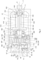
- FIG 2 is a simplified sectional view of the scroll machine 2 according to Figure 1 refer to.
- the scroll machine 2 has a machine housing 10, referred to as a whole, which is oriented along a longitudinal axis X.
- the machine housing 10 can have several housing parts, in which In the present exemplary embodiment, the machine housing 10 has a first housing part 10 ⁇ and a second housing part 10".
- a drive unit 400 In the machine housing 10 are along the longitudinal axis X Figure 2 From right to left the inlet 11, a drive unit 400, a drive shaft 420, a first spiral unit 100, a second spiral unit 200, an intermediate floor 50, a high pressure chamber 30 and the outlet 12 are arranged.
- the first spiral unit 100 is coupled to the drive unit 400 via an eccentric drive 150 and the drive shaft 420.
- the drive unit 400 preferably comprises an electric drive with a rotor 410 and a stator 415, the rotor 410 being firmly coupled to the drive shaft 420.
- the drive shaft 420 is aligned in the longitudinal axis X and the axis of rotation of the drive shaft 420 defines the longitudinal axis
- the drive shaft 420 is supported on the machine housing 10 by a first bearing unit 450 and in the second end section by a second bearing unit 300.
- the rotor 410 of the drive unit 400 is arranged between the first storage unit 450 and the second storage unit 300.
- the drive shaft 420 has a hollow shaft section 424, which is oriented in the longitudinal axis X.
- the hollow shaft section 424 can be designed as a blind hole and extends from a free end face of the drive shaft 420 in the first end section in the direction of the second end section.
- the drive shaft 420 also includes a plurality of radial bores 428, which break through the drive shaft 420 and connect the hollow shaft section 424 to an outer surface of the drive shaft 420.
- the drive shaft 420 can each have at least one radial bore 428 between the first bearing unit 450 and the rotor 410 and/or between the second bearing unit 300 and the rotor 410.
- the drive shaft 420 has two radial bores 428 between the first bearing unit 450 and the rotor 410 and between the second bearing unit 300 and the rotor 410, which are arranged circumferentially symmetrically to the drive shaft 420.
- the first bearing unit 450 includes a bearing holder 452 and a secondary bearing body 455.
- the bearing holder 452 can be formed by the machine housing 10.
- the secondary bearing body 455 can be designed as a rolling bearing, which is preferably not sealed.
- the first storage unit 450 divides an interior of the machine housing 10 into an inlet section and a drive section, with the inlet 11 opening into the inlet section.
- the inlet 11 is preferably arranged on an end face of the machine housing 10, with the inlet 11 even more preferably being arranged in alignment with the drive shaft 420 - preferably directly - in front of the free end face of the drive shaft 420.
- the second bearing unit 300 includes a main bearing housing 302 and a main bearing body 305.
- the main bearing body 305 can be designed as a rolling bearing, preferably not sealed.
- the second storage unit 300 further separates the interior of the machine housing 10 into the drive section and a suction area 320.
- the second bearing unit 300 has a first side and a second side, with the first side facing the drive unit 400 and the second side facing the first spiral unit 100.
- the main bearing body 305 is arranged on the first side and forms an end face on the second side Thrust bearing 190 for the first spiral unit 100.
- the second bearing unit 300 or the main bearing housing 302 can be bell-shaped or cup-shaped and enclose a space 380 together with the first spiral unit 100.
- the space 380 has a plurality of inlet openings 370, which are formed in the second bearing unit 300 or in the main bearing housing 302.
- the inlet openings 370 break through the main bearing housing 302 and open into the space 380.
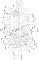
- the second bearing unit 300 can have four inlet openings 370, which are as in Figure 5 is shown, can be arranged circumferentially symmetrically on a lateral surface, preferably approximately centrally between the first side and the second side.
- the space 380 can have a plurality of outlet openings 390, which are preferably formed in the second bearing unit 300 or the main bearing housing 302.
- Figure 3 shows an enlarged detailed view according to Figure 2 from which it can be seen that the outlet opening 390 can be formed from a first bore section 392 and a second bore section 394 in the main bearing housing 302.
- the first bore section 392 is essentially radially oriented and extends from the space 380. For manufacturing reasons, it may be advantageous if the first bore section 392 completely penetrates the main bearing housing 302.
- the second bore section 394 is essentially axially oriented and connects the second side of the second bearing unit 300 or the main bearing housing 302 with the first bore section 392.
- the second storage unit 300 can have four outlet openings 390, which are preferably arranged circumferentially symmetrical. Furthermore, the outlet openings 390 can be opposite the inlet openings 370 - as in Figure 5 indicated - be arranged offset in the circumferential direction.
- the drive shaft 420 protrudes into the space 380 through the second bearing unit 300 or through the main bearing body 305.
- the space 380 there is a balancing mass 430 arranged on the drive shaft 420.
- the eccentric drive 150 is arranged, which includes an eccentric shaft section 152 and an eccentric bearing body 155 arranged on the eccentric shaft section 152.
- the eccentric shaft section 152 can be formed by the drive shaft 420.
- the first spiral unit 100 has a first side 101 and a second side 102 opposite the first side 101 in the longitudinal axis X. On the first side 101, the first spiral unit 100 is mounted on the second bearing unit 300 by means of the axial bearing 190.
- the eccentric drive 150 is coupled to the first spiral unit 100 on the first side 101 and a first spiral rib 110 is arranged on the second side 102, which projects along the longitudinal axis X and forms a first spiral channel 120.
- a ring-pin coupling 350 which has several ring-pin coupling pairs 351 (see Figures 4 or 5 ).
- the ring-pin coupling pairs form the ring-pin coupling 350, which prevents complete rotation of the first spiral unit 100 about the longitudinal axis X.
- the ring-pin coupling 350 couples the first spiral unit 100 with the second bearing unit 300 and includes a pin 356 and an abutment that can be formed by a recess 352 and a sleeve 354 arranged in the recess 352.
- the pin 356 can make a movement corresponding to the orbital path in the abutment.
- the abutment can be formed in the second bearing unit 300 and the pins 356 protrude from the first side 101 of the first spiral unit 100 and engage in the abutment of the second bearing unit 300.
- a ring-pin coupling pair 351 can have a connecting hole 360, which breaks through the second bearing unit 300 or the main bearing housing 302.
- first spiral rib 110 on the second side 102 of the first spiral unit 100 forms the spiral channel 120 with a spiral channel bottom.
- the spiral rib 110 also has a first spiral rib tip, which can either have a seal or can be designed as a flat tip.
- the first spiral channel 120 can have an inner end region 125 and/or an outer end region 126.
- the first spiral rib 110 is involute-shaped and extends from the inner end region 125 to the outer end region 126.
- the inner end region 125 lies radially inward with respect to the longitudinal axis X and the outer end region 126 lies radially outside with respect to the longitudinal axis X.
- the at least one spiral channel 120 is U-shaped and is delimited in the radial directions by the spiral rib 110 or a spiral wall of the spiral rib 110 and the spiral channel bottom.
- the second spiral unit 200 can be designed to be stationary and has a first side 201 and a second side 202 opposite the first side 201 in the longitudinal axis X. On the first side 201, a second spiral rib 210 protrudes along the longitudinal axis X, the second spiral rib 210 forming a second spiral channel 220.
- the second spiral rib 210 also has a second spiral rib tip, which can either have a seal or can be designed as a flat tip. Furthermore, the second spiral channel 220 can have an inner end region 225 and/or an outer end region 226.
- the second spiral rib 210 is adapted to the first spiral rib 110 and is also involute-shaped and extends from the inner end region 225 to an outer end region 226.
- the inner end region 225 lies radially inward with respect to the longitudinal axis X and the outer end region 226 with respect to the Longitudinal axis X radially outside.
- the at least one second spiral channel 220 is U-shaped and is delimited in the radial directions by the second spiral rib 210 or a spiral wall of the second spiral rib 210 and the second spiral channel bottom.
- first spiral rib 110 of the first spiral unit 100 and the second spiral rib 210 of the second spiral unit 200 engage with one another or mesh.
- the first spiral unit 100 can be moved by the drive unit 400 along an orbital path (not shown) relative to the second spiral unit 200.
- a ring-pin coupling 350 prevents the first spiral unit 100 from rotating about the longitudinal axis X during movement along the orbital path.
- the first spiral rib 110 engages in the second spiral channel 220 and the second spiral rib 210 engages in the first spiral channel 120.
- the second spiral rib tip of the second spiral rib 210 cooperates in a sealing manner with the spiral channel bottom of the first spiral unit 100 and the first spiral rib tip of the first spiral rib 110 interacts with the spiral channel base of the second spiral unit 200.
- first spiral unit 100 moves along the orbital path between the first Spiral unit 100 and the second spiral unit 200 (not shown) include pressure chambers through which medium is displaced from the outer end regions 126, 226 to the inner end regions 125, 225.
- the outer end regions 126, 226 together form the suction region 320, from which the medium can be sucked into the spiral channels 120, 220 in order to then transport it in closed pressure chambers (not shown) from the outer end region 126, 226 to the inner end region 125, 225 to relocate, whereby the pressure chambers experience a continuous volume reduction.
- the medium is guided in the machine housing 10 along several flow paths from the inlet 11 to the outer end regions 126, 226, the medium being used along these flow paths to cool the components in the machine housing 10 and/or to lubricate them using entrained lubricant.
- the flow paths are indicated by arrow lines, with only some of the arrow lines being marked with the reference symbol “S” for better understanding.
- the medium enters the inlet section through the inlet 11 in the machine housing 10. The medium then flows from the inlet section into the drive section.
- the medium branches out and flows along two parallel flow paths in the direction of the drive section, one of the flow paths being guided through the first bearing unit 550 and the other flow path being guided through the drive shaft 420 or through the hollow shaft section 424 of the drive shaft 420.
- the medium can flow from the hollow shaft section 424 into the drive section through the radial bore 428 of the drive shaft 420.
- the drive shaft 420 can have one or more radial bores 428 both between the first bearing unit 450 and the rotor 410 and between the rotor 410 and the second bearing unit 300, whereby the flow path guided through the hollow shaft section 424 branches out several times and is used for cooling and/or Lubrication, for example, of the rotor 410, the first bearing unit 300 and/or the second bearing unit 450 is used.
- the drive unit 400 has or has at least one axial opening 414 and / or at least one axial groove 418, each of which leads a flow path through the drive unit 400.
- the respective axial opening 414 and the respective axial groove 418 connect the two opposite end faces of the drive device 400, whereby the drive unit 400 is "flushed" with the medium.
- a very effective cooling of the drive unit 400 can be achieved by this measure.
- the at least one axial opening 414 can be formed by a running gap between the rotor 410 and the stator 415.
- the medium then flows from the drive section along several flow paths through the second storage unit 300 into the suction area 320.
- the medium can be guided via the space 380 to the suction area 320 and on the other hand via the connecting bore 360 in the ring-pin coupling 350 or in the at least one ring-pin coupling pair 351.
- the medium can be guided into the space 380 along two flow paths connected in parallel, one of the flow paths leading through the inlet openings 370 and the other of the flow paths through the main bearing body 305. In this way, the main bearing body 305 can both be cooled, as well as by the lubricant carried with the medium.
- the medium flows around the balancing mass 430 and the eccentric drive 150 of the first spiral unit 100, whereby these components can be both cooled and lubricated.
- the medium can have space 380 - as shown in the enlarged view Figures 3 and 5 can be removed - exit through the outlet openings 390, which connect the space 380 with the suction area 320 or the outer end areas 126, 226 of the first spiral unit 100 and the second spiral unit 200.
- the outlet openings 390 open into the suction area 320 on the second side of the second bearing unit 300 facing the first spiral unit 100, the respective outlet opening 390 preferably opening within an area which is completely or partially covered by the first spiral unit 100 during a complete movement along the orbital path is run over.
- the first spiral unit 100 has a recess 290 on the side facing the at least one outlet opening 390, which is arranged within a surface which passes over the at least one outlet opening 390 during a complete movement along the orbital path.
- the respective outlet opening 390 and the first spiral unit 100 therefore do not come into contact.
- a flow path can be guided from the drive section and the suction region 320 through the ring-pin coupling 350 and the ring-pin coupling pairs 351, respectively.
- the respective ring-pin coupling pair 351 can have a connecting bore 360 (see FIG. 5), which leads a further flow path from the inlet 11 to the suction area 320.
- the connecting bores 360 break through the second bearing unit 300 and connect the first side of the second bearing unit 300 with the recess 352 of the first spiral unit 100.
- a reduction in the pressure drop of the medium can be achieved through the connecting bores 360 in the ring-pin coupling pairs 351.
- At least one connecting hole 360 can be provided, which connects the second bearing unit 300 between two ring-pin coupling pairs 351 breaks through and leads a flow path from the inlet 11 to the suction area 320.
- the outlet openings 390 can be formed by a plurality of radially oriented axial recesses which are arranged on the second side of the second bearing unit 300.
- the axial recesses can extend over the second side of the second bearing unit 300 and thus also over the axial bearing 190 formed between the second bearing unit 300 and the first spiral unit 100.
- the lubricant carried in the medium can contribute to the lubrication of the axial bearing 190 when the first spiral unit 100 travels over the recessed areas.
- this development can include an axial bearing element that can be arranged in the form of a plate between the second bearing unit 300 and the first spiral unit 100.
- the axial bearing element is preferably an axial bearing plate.
- the high-pressure chamber 30 and the intermediate floor 50 are arranged on the second side 202 of the second spiral unit 200, the intermediate floor 50 being arranged along the longitudinal axis X between the high-pressure chamber 30 and the second spiral unit 200.
- the intermediate floor 50 decouples the second spiral unit 200 from the pressure forces in the high-pressure chamber 30 and is supported relative to the machine housing 10.
- the high-pressure chamber 30 is connected to the second spiral channel 220 via a passage 260, the passage 260 comprises an outlet opening which is arranged in the region of the inner end regions 125, 225.
- the outlet opening also called “discharge port”
- the passage 260 extends along the longitudinal axis X through an opening through the intermediate floor 50 to the high-pressure chamber 30.
- the high pressure chamber 30 is in turn connected to the outlet 12 and the medium can leave the scroll machine 2 through the outlet 12.
- the high-pressure chamber 30 is surrounded or enclosed by the machine housing 10 and the intermediate floor 50 and has the outlet 12 through which the medium can leave the scroll machine.
- the machine housing 10 or the second housing part 10" can be pot-shaped with a recess, the intermediate base 50 being able to close the high-pressure chamber 30 in the machine housing 10 or the second housing section 10" in the manner of a cover or plug.
- the shapes of the recess of the second housing section 10" and the intermediate floor 50 are adapted to one another, with both the recess and the intermediate floor 50 preferably having a circular cylindrical shape and being able to be designed to fit one another precisely.
- sealants can be provided there.
- the intermediate floor 50 has a first side and a second side, the first side facing the second spiral unit 200, and the second side facing the high-pressure chamber 30.
- the intermediate floor 50 includes the opening through which the passage 260 is guided.
- the intermediate floor 50 has an annular projection which protrudes on the first side of the intermediate floor 50 in the longitudinal axis X from the first side of the intermediate floor 50 in the direction of the second spiral unit 200.
- an axial lock in the form of a locking ring fastened in the machine housing 10 can be arranged, through which the position of the intermediate floor 50 in the longitudinal axis X is determined.
- the axial securing supports the intermediate floor 50 on the side facing the second spiral unit 200 on the machine housing 10, whereby the pressure forces from the high-pressure chamber 30 are essentially decoupled from the second spiral unit 200 and are coupled into the machine housing 10.
- the second spiral unit 200 can telescope around the annular projection of the intermediate floor 50 and for this purpose has a first annular projection and a second annular projection on the second side 202, the first annular projection interacting with an inner lateral surface of the annular projection and the second annular projection with an outer lateral surface of the annular projection of the intermediate base 50.
- the annular projection of the intermediate floor 50 as well as the annular projections surrounding the annular projection of the intermediate floor 50 on the second side 202 of the second spiral unit 200 do not necessarily have to be provided, but represent a preferred development that can be used in particular when the scroll machine 1 has an injection or an eco-port.
- the annular projections of the intermediate floor 50 and the annular projections of the second spiral unit 200 can form a radial bearing for the second spiral unit 200.
- the medium can - as shown by the arrow lines in Figure 2 is shown - from the high pressure chamber 30 via a pressure port 40 to the outlet 12, the pressure port 40 preferably being arranged in such a way that the medium cannot flow directly from the passage 260 into the pressure port 40.
- the pressure port 40 projects from the side of the machine housing 10 facing the intermediate floor 50 in the direction of the intermediate floor 50 and, according to FIG. 7, is arranged offset from the passage 260 in a plane perpendicular to the longitudinal axis X.
- a return flow area 45 can be provided, which forces an S-shaped flow path S from the passage 260 through the pressure port 40 to the outlet 12, which in Figure 2 indicated by an arrow line.
- the return flow area 45 can have a preferably annular recess 59 (see Figure 6 ), which together with the pressure port defines the S-shaped flow path.
- the pressure port 40 is connected to the intermediate floor 50 according to Figure 6 in one Contact area 46 in effective contact, the contact area 46 being arranged on an imaginary connecting line in a plane perpendicular to the longitudinal axis X between the pressure port 40 and the passage 260.
- Check valve 48 shown may be arranged, which preferably comprises a bushing 49 which can be inserted into the pressure port 40.
Landscapes
- Engineering & Computer Science (AREA)
- Mechanical Engineering (AREA)
- General Engineering & Computer Science (AREA)
- Rotary Pumps (AREA)
- Applications Or Details Of Rotary Compressors (AREA)
- Physics & Mathematics (AREA)
- Thermal Sciences (AREA)
Applications Claiming Priority (1)
| Application Number | Priority Date | Filing Date | Title |
|---|---|---|---|
| DE102022120679.3A DE102022120679A1 (de) | 2022-08-16 | 2022-08-16 | Scrollmaschine und Kälteanlage |
Publications (3)
| Publication Number | Publication Date |
|---|---|
| EP4336043A2 true EP4336043A2 (fr) | 2024-03-13 |
| EP4336043A3 EP4336043A3 (fr) | 2024-04-03 |
| EP4336043B1 EP4336043B1 (fr) | 2026-03-18 |
Family
ID=87047571
Family Applications (1)
| Application Number | Title | Priority Date | Filing Date |
|---|---|---|---|
| EP23181521.8A Active EP4336043B1 (fr) | 2022-08-16 | 2023-06-26 | Machine à spirales et système frigorifique |
Country Status (4)
| Country | Link |
|---|---|
| US (2) | US12331743B2 (fr) |
| EP (1) | EP4336043B1 (fr) |
| CN (1) | CN117588410A (fr) |
| DE (1) | DE102022120679A1 (fr) |
Families Citing this family (1)
| Publication number | Priority date | Publication date | Assignee | Title |
|---|---|---|---|---|
| DE102022120679A1 (de) * | 2022-08-16 | 2024-02-22 | Bitzer Kühlmaschinenbau Gmbh | Scrollmaschine und Kälteanlage |
Citations (1)
| Publication number | Priority date | Publication date | Assignee | Title |
|---|---|---|---|---|
| WO2018019372A1 (fr) | 2016-07-27 | 2018-02-01 | Bitzer Kühlmaschinenbau Gmbh | Compresseur |
Family Cites Families (16)
| Publication number | Priority date | Publication date | Assignee | Title |
|---|---|---|---|---|
| AU613949B2 (en) * | 1987-09-08 | 1991-08-15 | Sanden Corporation | Hermetic scroll type compressor |
| JP3870642B2 (ja) * | 1999-12-21 | 2007-01-24 | 株式会社デンソー | 電動圧縮機 |
| KR100427399B1 (ko) * | 2000-12-28 | 2004-04-17 | 라필찬 | 고, 저압부가 일체로 장착된 스크롤 유체기계 |
| US6887050B2 (en) * | 2002-09-23 | 2005-05-03 | Tecumseh Products Company | Compressor having bearing support |
| US7914268B2 (en) * | 2007-09-11 | 2011-03-29 | Emerson Climate Technologies, Inc. | Compressor having shell with alignment features |
| JP2009150234A (ja) * | 2007-12-18 | 2009-07-09 | Toyota Industries Corp | 電動圧縮機 |
| JP5285988B2 (ja) * | 2008-07-25 | 2013-09-11 | 日立アプライアンス株式会社 | 横型スクロール圧縮機 |
| WO2014002970A1 (fr) * | 2012-06-27 | 2014-01-03 | 株式会社豊田自動織機 | Compresseur à spirale |
| JP2014070582A (ja) * | 2012-09-28 | 2014-04-21 | Toyota Industries Corp | 電動圧縮機及び空調装置 |
| JP6147605B2 (ja) * | 2013-08-02 | 2017-06-14 | 三菱重工業株式会社 | 圧縮機 |
| US10801495B2 (en) * | 2016-09-08 | 2020-10-13 | Emerson Climate Technologies, Inc. | Oil flow through the bearings of a scroll compressor |
| US11111921B2 (en) * | 2017-02-06 | 2021-09-07 | Emerson Climate Technologies, Inc. | Co-rotating compressor |
| KR102087141B1 (ko) * | 2018-09-06 | 2020-03-10 | 엘지전자 주식회사 | 전동식 압축기 |
| US20230258186A1 (en) * | 2020-06-23 | 2023-08-17 | Emerson Climate Technologies (Suzhou) Co., Ltd. | Scroll compression mechanism and scroll compressor |
| JP7439690B2 (ja) * | 2020-08-05 | 2024-02-28 | 株式会社デンソー | 圧縮機、圧縮機の製造方法 |
| DE102022120679A1 (de) * | 2022-08-16 | 2024-02-22 | Bitzer Kühlmaschinenbau Gmbh | Scrollmaschine und Kälteanlage |
-
2022
- 2022-08-16 DE DE102022120679.3A patent/DE102022120679A1/de active Pending
-
2023
- 2023-06-26 EP EP23181521.8A patent/EP4336043B1/fr active Active
- 2023-08-11 US US18/233,201 patent/US12331743B2/en active Active
- 2023-08-11 CN CN202311011474.1A patent/CN117588410A/zh active Pending
-
2025
- 2025-05-22 US US19/215,697 patent/US20250283467A1/en active Pending
Patent Citations (1)
| Publication number | Priority date | Publication date | Assignee | Title |
|---|---|---|---|---|
| WO2018019372A1 (fr) | 2016-07-27 | 2018-02-01 | Bitzer Kühlmaschinenbau Gmbh | Compresseur |
Also Published As
| Publication number | Publication date |
|---|---|
| US20250283467A1 (en) | 2025-09-11 |
| US20240060491A1 (en) | 2024-02-22 |
| CN117588410A (zh) | 2024-02-23 |
| EP4336043A3 (fr) | 2024-04-03 |
| EP4336043B1 (fr) | 2026-03-18 |
| DE102022120679A1 (de) | 2024-02-22 |
| US12331743B2 (en) | 2025-06-17 |
Similar Documents
| Publication | Publication Date | Title |
|---|---|---|
| DE69115422T2 (de) | Spiralverdichter mit schwimmender Abdichtung | |
| DE112015004113B4 (de) | Kompressor mit Ölrückführeinheit | |
| DE602004002054T2 (de) | Spiralverdichter mit Auslassventil | |
| DE2735663A1 (de) | Spiralartige einrichtung mit einem hydrodynamischen axiallager | |
| DE112014002604B4 (de) | Antriebswelle für Scroll-Verdichter und Scroll-Verdichter | |
| DE2801206A1 (de) | Spiralartige einrichtung mit einem festen gekroepften kurbelantriebsmechanismus | |
| DE3127323A1 (de) | Schraubenkompressor mit geschlossenem druckgassystem mit oelnebelschmierung | |
| DE102016121241B4 (de) | Hydraulischer Antrieb, hydraulischer Motor und integrierte Pumpe mit dem hydraulischen Antrieb | |
| EP1307657B1 (fr) | Pompe a vide a deux arbres | |
| DE102020210453B4 (de) | Scrollverdichter eines elektrischen Kältemittelantriebs | |
| EP4264053B1 (fr) | Compresseur à spirale pour la production d'air comprimé sans huile | |
| EP4336043B1 (fr) | Machine à spirales et système frigorifique | |
| DE69003012T2 (de) | Axialdichtungseinrichtung für Spiralverdichter. | |
| DE69631485T2 (de) | Spiralverdichter mit einem plattenförmigen axialgleitlage | |
| DE2346702A1 (de) | Rotationskompressor des lamellentyps | |
| EP4325055B1 (fr) | Machine à spirales à injection et système frigorifique | |
| DE3826548C2 (de) | Flügelzellenverdichter mit variabler Förderleistung | |
| EP0711384A1 (fr) | Pompe a vide a palette a deux etages | |
| DE102020207510A1 (de) | Verdichtermodul sowie elektromotorischer Kältemittelverdichter | |
| DE102019208680A1 (de) | Verdrängermaschine nach dem Spiralprinzip, insbesondere Scrollverdichter für eine Fahrzeugklimaanlage | |
| DE102017102645B4 (de) | Kältemittel-Scrollverdichter für die Verwendung innerhalb einer Wärmepumpe | |
| DE4220830A1 (de) | Fluidverdichter | |
| EP4325056B1 (fr) | Machine à spirales et système frigorifique | |
| DE19949730A1 (de) | Wassergekühlte Gaszuführvorrichtung mit Wasserdrainagesystem | |
| DE102020109556B4 (de) | Vorrichtungen zum Verdichten eines gasförmigen Fluids und Verfahren zum Betreiben der Vorrichtungen |
Legal Events
| Date | Code | Title | Description |
|---|---|---|---|
| PUAI | Public reference made under article 153(3) epc to a published international application that has entered the european phase |
Free format text: ORIGINAL CODE: 0009012 |
|
| STAA | Information on the status of an ep patent application or granted ep patent |
Free format text: STATUS: THE APPLICATION HAS BEEN PUBLISHED |
|
| PUAL | Search report despatched |
Free format text: ORIGINAL CODE: 0009013 |
|
| AK | Designated contracting states |
Kind code of ref document: A2 Designated state(s): AL AT BE BG CH CY CZ DE DK EE ES FI FR GB GR HR HU IE IS IT LI LT LU LV MC ME MK MT NL NO PL PT RO RS SE SI SK SM TR |
|
| AK | Designated contracting states |
Kind code of ref document: A3 Designated state(s): AL AT BE BG CH CY CZ DE DK EE ES FI FR GB GR HR HU IE IS IT LI LT LU LV MC ME MK MT NL NO PL PT RO RS SE SI SK SM TR |
|
| RIC1 | Information provided on ipc code assigned before grant |
Ipc: F04C 29/12 20060101ALI20240228BHEP Ipc: F04C 29/02 20060101ALI20240228BHEP Ipc: F04C 23/00 20060101ALI20240228BHEP Ipc: F04C 18/02 20060101AFI20240228BHEP |
|
| RIN1 | Information on inventor provided before grant (corrected) |
Inventor name: VARGA, THOMAS Inventor name: SCHARER, CHRISTIAN Inventor name: HAUSER, MARKUS |
|
| STAA | Information on the status of an ep patent application or granted ep patent |
Free format text: STATUS: REQUEST FOR EXAMINATION WAS MADE |
|
| 17P | Request for examination filed |
Effective date: 20241001 |
|
| RBV | Designated contracting states (corrected) |
Designated state(s): AL AT BE BG CH CY CZ DE DK EE ES FI FR GB GR HR HU IE IS IT LI LT LU LV MC ME MK MT NL NO PL PT RO RS SE SI SK SM TR |
|
| GRAP | Despatch of communication of intention to grant a patent |
Free format text: ORIGINAL CODE: EPIDOSNIGR1 |
|
| STAA | Information on the status of an ep patent application or granted ep patent |
Free format text: STATUS: GRANT OF PATENT IS INTENDED |
|
| INTG | Intention to grant announced |
Effective date: 20251031 |
|
| GRAS | Grant fee paid |
Free format text: ORIGINAL CODE: EPIDOSNIGR3 |
|
| GRAA | (expected) grant |
Free format text: ORIGINAL CODE: 0009210 |
|
| STAA | Information on the status of an ep patent application or granted ep patent |
Free format text: STATUS: THE PATENT HAS BEEN GRANTED |
|
| AK | Designated contracting states |
Kind code of ref document: B1 Designated state(s): AL AT BE BG CH CY CZ DE DK EE ES FI FR GB GR HR HU IE IS IT LI LT LU LV MC ME MK MT NL NO PL PT RO RS SE SI SK SM TR |
|
| REG | Reference to a national code |
Ref country code: CH Ref legal event code: F10 Free format text: ST27 STATUS EVENT CODE: U-0-0-F10-F00 (AS PROVIDED BY THE NATIONAL OFFICE) Effective date: 20260318 Ref country code: GB Ref legal event code: FG4D Free format text: NOT ENGLISH |
|
| P01 | Opt-out of the competence of the unified patent court (upc) registered |
Free format text: CASE NUMBER: UPC_APP_0006804_4336043/2026 Effective date: 20260225 |
|
| REG | Reference to a national code |
Ref country code: DE Ref legal event code: R096 Ref document number: 502023003396 Country of ref document: DE |
|
| REG | Reference to a national code |
Ref country code: IE Ref legal event code: FG4D Free format text: LANGUAGE OF EP DOCUMENT: GERMAN |