EP4336126A1 - Installation frigorifique et procédé de fonctionnement d'une installation frigorifique - Google Patents
Installation frigorifique et procédé de fonctionnement d'une installation frigorifique Download PDFInfo
- Publication number
- EP4336126A1 EP4336126A1 EP23195128.6A EP23195128A EP4336126A1 EP 4336126 A1 EP4336126 A1 EP 4336126A1 EP 23195128 A EP23195128 A EP 23195128A EP 4336126 A1 EP4336126 A1 EP 4336126A1
- Authority
- EP
- European Patent Office
- Prior art keywords
- refrigerant
- compressor
- heat exchanger
- control valve
- natural circulation
- Prior art date
- Legal status (The legal status is an assumption and is not a legal conclusion. Google has not performed a legal analysis and makes no representation as to the accuracy of the status listed.)
- Withdrawn
Links
Images

Classifications
-
- F—MECHANICAL ENGINEERING; LIGHTING; HEATING; WEAPONS; BLASTING
- F25—REFRIGERATION OR COOLING; COMBINED HEATING AND REFRIGERATION SYSTEMS; HEAT PUMP SYSTEMS; MANUFACTURE OR STORAGE OF ICE; LIQUEFACTION SOLIDIFICATION OF GASES
- F25B—REFRIGERATION MACHINES, PLANTS OR SYSTEMS; COMBINED HEATING AND REFRIGERATION SYSTEMS; HEAT PUMP SYSTEMS
- F25B49/00—Arrangement or mounting of control or safety devices
- F25B49/02—Arrangement or mounting of control or safety devices for compression type machines, plants or systems
-
- F—MECHANICAL ENGINEERING; LIGHTING; HEATING; WEAPONS; BLASTING
- F25—REFRIGERATION OR COOLING; COMBINED HEATING AND REFRIGERATION SYSTEMS; HEAT PUMP SYSTEMS; MANUFACTURE OR STORAGE OF ICE; LIQUEFACTION SOLIDIFICATION OF GASES
- F25B—REFRIGERATION MACHINES, PLANTS OR SYSTEMS; COMBINED HEATING AND REFRIGERATION SYSTEMS; HEAT PUMP SYSTEMS
- F25B9/00—Compression machines, plants or systems, in which the refrigerant is air or other gas of low boiling point
- F25B9/002—Compression machines, plants or systems, in which the refrigerant is air or other gas of low boiling point characterised by the refrigerant
- F25B9/004—Compression machines, plants or systems, in which the refrigerant is air or other gas of low boiling point characterised by the refrigerant the refrigerant being air
-
- F—MECHANICAL ENGINEERING; LIGHTING; HEATING; WEAPONS; BLASTING
- F17—STORING OR DISTRIBUTING GASES OR LIQUIDS
- F17C—VESSELS FOR CONTAINING OR STORING COMPRESSED, LIQUEFIED OR SOLIDIFIED GASES; FIXED-CAPACITY GAS-HOLDERS; FILLING VESSELS WITH, OR DISCHARGING FROM VESSELS, COMPRESSED, LIQUEFIED, OR SOLIDIFIED GASES
- F17C5/00—Methods or apparatus for filling containers with liquefied, solidified, or compressed gases under pressures
-
- F—MECHANICAL ENGINEERING; LIGHTING; HEATING; WEAPONS; BLASTING
- F25—REFRIGERATION OR COOLING; COMBINED HEATING AND REFRIGERATION SYSTEMS; HEAT PUMP SYSTEMS; MANUFACTURE OR STORAGE OF ICE; LIQUEFACTION SOLIDIFICATION OF GASES
- F25B—REFRIGERATION MACHINES, PLANTS OR SYSTEMS; COMBINED HEATING AND REFRIGERATION SYSTEMS; HEAT PUMP SYSTEMS
- F25B41/00—Fluid-circulation arrangements
- F25B41/20—Disposition of valves, e.g. of on-off valves or flow control valves
-
- F—MECHANICAL ENGINEERING; LIGHTING; HEATING; WEAPONS; BLASTING
- F25—REFRIGERATION OR COOLING; COMBINED HEATING AND REFRIGERATION SYSTEMS; HEAT PUMP SYSTEMS; MANUFACTURE OR STORAGE OF ICE; LIQUEFACTION SOLIDIFICATION OF GASES
- F25B—REFRIGERATION MACHINES, PLANTS OR SYSTEMS; COMBINED HEATING AND REFRIGERATION SYSTEMS; HEAT PUMP SYSTEMS
- F25B49/00—Arrangement or mounting of control or safety devices
- F25B49/02—Arrangement or mounting of control or safety devices for compression type machines, plants or systems
- F25B49/027—Condenser control arrangements
-
- F—MECHANICAL ENGINEERING; LIGHTING; HEATING; WEAPONS; BLASTING
- F25—REFRIGERATION OR COOLING; COMBINED HEATING AND REFRIGERATION SYSTEMS; HEAT PUMP SYSTEMS; MANUFACTURE OR STORAGE OF ICE; LIQUEFACTION SOLIDIFICATION OF GASES
- F25B—REFRIGERATION MACHINES, PLANTS OR SYSTEMS; COMBINED HEATING AND REFRIGERATION SYSTEMS; HEAT PUMP SYSTEMS
- F25B9/00—Compression machines, plants or systems, in which the refrigerant is air or other gas of low boiling point
- F25B9/10—Compression machines, plants or systems, in which the refrigerant is air or other gas of low boiling point with several cooling stages
-
- F—MECHANICAL ENGINEERING; LIGHTING; HEATING; WEAPONS; BLASTING
- F17—STORING OR DISTRIBUTING GASES OR LIQUIDS
- F17C—VESSELS FOR CONTAINING OR STORING COMPRESSED, LIQUEFIED OR SOLIDIFIED GASES; FIXED-CAPACITY GAS-HOLDERS; FILLING VESSELS WITH, OR DISCHARGING FROM VESSELS, COMPRESSED, LIQUEFIED, OR SOLIDIFIED GASES
- F17C2221/00—Handled fluid, in particular type of fluid
- F17C2221/01—Pure fluids
- F17C2221/012—Hydrogen
-
- F—MECHANICAL ENGINEERING; LIGHTING; HEATING; WEAPONS; BLASTING
- F17—STORING OR DISTRIBUTING GASES OR LIQUIDS
- F17C—VESSELS FOR CONTAINING OR STORING COMPRESSED, LIQUEFIED OR SOLIDIFIED GASES; FIXED-CAPACITY GAS-HOLDERS; FILLING VESSELS WITH, OR DISCHARGING FROM VESSELS, COMPRESSED, LIQUEFIED, OR SOLIDIFIED GASES
- F17C2227/00—Transfer of fluids, i.e. method or means for transferring the fluid; Heat exchange with the fluid
- F17C2227/03—Heat exchange with the fluid
- F17C2227/0337—Heat exchange with the fluid by cooling
- F17C2227/0341—Heat exchange with the fluid by cooling using another fluid
- F17C2227/0355—Heat exchange with the fluid by cooling using another fluid in a closed loop
-
- F—MECHANICAL ENGINEERING; LIGHTING; HEATING; WEAPONS; BLASTING
- F17—STORING OR DISTRIBUTING GASES OR LIQUIDS
- F17C—VESSELS FOR CONTAINING OR STORING COMPRESSED, LIQUEFIED OR SOLIDIFIED GASES; FIXED-CAPACITY GAS-HOLDERS; FILLING VESSELS WITH, OR DISCHARGING FROM VESSELS, COMPRESSED, LIQUEFIED, OR SOLIDIFIED GASES
- F17C2265/00—Effects achieved by gas storage or gas handling
- F17C2265/06—Fluid distribution
- F17C2265/065—Fluid distribution for refuelling vehicle fuel tanks
-
- F—MECHANICAL ENGINEERING; LIGHTING; HEATING; WEAPONS; BLASTING
- F25—REFRIGERATION OR COOLING; COMBINED HEATING AND REFRIGERATION SYSTEMS; HEAT PUMP SYSTEMS; MANUFACTURE OR STORAGE OF ICE; LIQUEFACTION SOLIDIFICATION OF GASES
- F25B—REFRIGERATION MACHINES, PLANTS OR SYSTEMS; COMBINED HEATING AND REFRIGERATION SYSTEMS; HEAT PUMP SYSTEMS
- F25B2339/00—Details of evaporators; Details of condensers
- F25B2339/04—Details of condensers
- F25B2339/047—Water-cooled condensers
-
- F—MECHANICAL ENGINEERING; LIGHTING; HEATING; WEAPONS; BLASTING
- F25—REFRIGERATION OR COOLING; COMBINED HEATING AND REFRIGERATION SYSTEMS; HEAT PUMP SYSTEMS; MANUFACTURE OR STORAGE OF ICE; LIQUEFACTION SOLIDIFICATION OF GASES
- F25B—REFRIGERATION MACHINES, PLANTS OR SYSTEMS; COMBINED HEATING AND REFRIGERATION SYSTEMS; HEAT PUMP SYSTEMS
- F25B2400/00—Component parts or details not otherwise provided for in this subclass
- F25B2400/04—Refrigeration circuit bypassing means
-
- F—MECHANICAL ENGINEERING; LIGHTING; HEATING; WEAPONS; BLASTING
- F25—REFRIGERATION OR COOLING; COMBINED HEATING AND REFRIGERATION SYSTEMS; HEAT PUMP SYSTEMS; MANUFACTURE OR STORAGE OF ICE; LIQUEFACTION SOLIDIFICATION OF GASES
- F25B—REFRIGERATION MACHINES, PLANTS OR SYSTEMS; COMBINED HEATING AND REFRIGERATION SYSTEMS; HEAT PUMP SYSTEMS
- F25B25/00—Machines, plants or systems, using a combination of modes of operation covered by two or more of the groups F25B1/00 - F25B23/00
- F25B25/005—Machines, plants or systems, using a combination of modes of operation covered by two or more of the groups F25B1/00 - F25B23/00 using primary and secondary systems
-
- F—MECHANICAL ENGINEERING; LIGHTING; HEATING; WEAPONS; BLASTING
- F25—REFRIGERATION OR COOLING; COMBINED HEATING AND REFRIGERATION SYSTEMS; HEAT PUMP SYSTEMS; MANUFACTURE OR STORAGE OF ICE; LIQUEFACTION SOLIDIFICATION OF GASES
- F25B—REFRIGERATION MACHINES, PLANTS OR SYSTEMS; COMBINED HEATING AND REFRIGERATION SYSTEMS; HEAT PUMP SYSTEMS
- F25B2600/00—Control issues
- F25B2600/11—Fan speed control
- F25B2600/111—Fan speed control of condenser fans
-
- F—MECHANICAL ENGINEERING; LIGHTING; HEATING; WEAPONS; BLASTING
- F25—REFRIGERATION OR COOLING; COMBINED HEATING AND REFRIGERATION SYSTEMS; HEAT PUMP SYSTEMS; MANUFACTURE OR STORAGE OF ICE; LIQUEFACTION SOLIDIFICATION OF GASES
- F25B—REFRIGERATION MACHINES, PLANTS OR SYSTEMS; COMBINED HEATING AND REFRIGERATION SYSTEMS; HEAT PUMP SYSTEMS
- F25B2600/00—Control issues
- F25B2600/25—Control of valves
- F25B2600/2501—Bypass valves
-
- F—MECHANICAL ENGINEERING; LIGHTING; HEATING; WEAPONS; BLASTING
- F25—REFRIGERATION OR COOLING; COMBINED HEATING AND REFRIGERATION SYSTEMS; HEAT PUMP SYSTEMS; MANUFACTURE OR STORAGE OF ICE; LIQUEFACTION SOLIDIFICATION OF GASES
- F25B—REFRIGERATION MACHINES, PLANTS OR SYSTEMS; COMBINED HEATING AND REFRIGERATION SYSTEMS; HEAT PUMP SYSTEMS
- F25B2600/00—Control issues
- F25B2600/25—Control of valves
- F25B2600/2515—Flow valves
-
- F—MECHANICAL ENGINEERING; LIGHTING; HEATING; WEAPONS; BLASTING
- F25—REFRIGERATION OR COOLING; COMBINED HEATING AND REFRIGERATION SYSTEMS; HEAT PUMP SYSTEMS; MANUFACTURE OR STORAGE OF ICE; LIQUEFACTION SOLIDIFICATION OF GASES
- F25B—REFRIGERATION MACHINES, PLANTS OR SYSTEMS; COMBINED HEATING AND REFRIGERATION SYSTEMS; HEAT PUMP SYSTEMS
- F25B2700/00—Sensing or detecting of parameters; Sensors therefor
- F25B2700/19—Pressures
- F25B2700/193—Pressures of the compressor
- F25B2700/1931—Discharge pressures
-
- F—MECHANICAL ENGINEERING; LIGHTING; HEATING; WEAPONS; BLASTING
- F25—REFRIGERATION OR COOLING; COMBINED HEATING AND REFRIGERATION SYSTEMS; HEAT PUMP SYSTEMS; MANUFACTURE OR STORAGE OF ICE; LIQUEFACTION SOLIDIFICATION OF GASES
- F25B—REFRIGERATION MACHINES, PLANTS OR SYSTEMS; COMBINED HEATING AND REFRIGERATION SYSTEMS; HEAT PUMP SYSTEMS
- F25B2700/00—Sensing or detecting of parameters; Sensors therefor
- F25B2700/21—Temperatures
- F25B2700/2103—Temperatures near a heat exchanger
-
- F—MECHANICAL ENGINEERING; LIGHTING; HEATING; WEAPONS; BLASTING
- F25—REFRIGERATION OR COOLING; COMBINED HEATING AND REFRIGERATION SYSTEMS; HEAT PUMP SYSTEMS; MANUFACTURE OR STORAGE OF ICE; LIQUEFACTION SOLIDIFICATION OF GASES
- F25B—REFRIGERATION MACHINES, PLANTS OR SYSTEMS; COMBINED HEATING AND REFRIGERATION SYSTEMS; HEAT PUMP SYSTEMS
- F25B2700/00—Sensing or detecting of parameters; Sensors therefor
- F25B2700/21—Temperatures
- F25B2700/2106—Temperatures of fresh outdoor air
Definitions
- the invention relates to a refrigeration system and a method for operating a refrigeration system.
- the hydrogen must be cooled.
- the pressure in the refrigerant-carrying system can drop or not build up at all when the refrigeration machine's compressor starts up.
- condenser pressure regulators can cause condensate to build up in the air-cooled condenser to reduce the free area of the heat exchanger.
- This conventional type of power limitation is comparatively expensive and requires increased amounts of refrigerant to enable accumulation.
- This type of performance limitation entails higher costs and further disadvantages in the form of environmental pollution and, in the case of flammable refrigerants, higher risks and fire loads.
- Another problem with large amounts of refrigerant can be a shift of significant amounts of refrigerant into the compressor's lubricating oil.
- the object of the invention is to improve known refrigeration systems, in particular the amount of refrigerant used should be minimized, the process cooling unit should have good starting properties even at comparatively low outside temperatures and refrigerant displacement into the lubricating oil of the compressor should be minimized and energy efficiency should be improved as much as possible.
- a first aspect of the invention relates to a refrigeration system, in particular for cooling a target fluid to a target temperature between -80 ° C and + 30 ° C using ambient air, comprising: a compressor refrigerant system with a compressor and a target heat exchanger for cooling the target -Fluids; further comprising a natural circulation refrigerant system with an ambient air condenser and a control valve, and with an intermediate heat exchanger that couples the natural circulation refrigerant system to the compressor refrigerant system.
- a further aspect of the invention relates to a method for cooling a target fluid to a target temperature of at least -80°C, at least -60°C or at least -45°C or at most +30°C, at most -10°C or at most - 35°C using ambient air using a refrigeration system in one of the typical embodiments described herein.
- the refrigeration system is typically set up to operate at ambient air temperatures at least down to -40°C or at least up to -20°C.
- compressor refrigerant The working fluid in the compressor refrigerant system is also referred to herein as compressor refrigerant.
- compressor refrigerant there is also lubricating oil for the compressor in the compressor refrigerant system, which is in a mixture equilibrium with the compressor refrigerant.
- Compressor refrigerant systems contain both conventional fluorinated gases (F-gases) such as: R-449A as well as "natural" refrigerants such as CO 2 (R-744) or propane (R-290)/propene (R-1270) are used as working fluid.
- an intermediate heat exchanger is typically installed as a condenser for the compressor refrigerant.
- this intermediate heat exchanger is arranged on the so-called cold side of the natural circulation refrigerant system. It typically thermally connects the compressor refrigerant system with the natural circulation refrigerant system.
- the respective refrigerants of the refrigerant systems typically remain separate.
- the working fluid in the natural circulation refrigerant system is also referred to herein as natural circulation refrigerant.
- natural circulation refrigerant both conventional fluorinated gases (F-gases) such as R-449A and "natural refrigerants” such as CO 2 (R-744) or propane (R-290)/propene (R-1270) can be used as working fluid are used.
- F-gases fluorinated gases
- natural refrigerants such as CO 2 (R-744) or propane (R-290)/propene (R-1270)
- the same working fluid as in the compressor refrigerant system can be used, this reduces the risk of mix-ups and simplifies storage and maintenance.
- it is also technically possible to use different working fluids for example to improve the efficiency of embodiments.
- the compressor refrigerant system includes a pressure sensor for determining a pressure of a compressor refrigerant located in the compressor refrigerant system.
- the pressure sensor is located downstream of the compressor, between the compressor and the intermediate heat exchanger.
- the pressure sensor determines the pressure of the compressor refrigerant directly after the compressor or at an inlet of the intermediate heat exchanger.
- the pressure sensor determines the pressure to which the compressor compresses the compressor refrigerant.
- the pressure may correspond to the condensation pressure of the compressor refrigerant.
- the degree of opening of the control valve is controlled such that the measured pressure is regulated to the condensation pressure or a target condensation pressure.
- the value of the target condensation pressure depends, among other things, on the refrigerant used and can, for example, be between 8 and 22 bar for propane (R-290)/propene (R-1270) or between 80 - 280 bar for CO 2 (R-744). lay.
- the target heat exchanger releases the cooling capacity of the compressor refrigerant system; the cooling capacity used corresponds to the useful cooling capacity of the refrigeration system.
- the condensation pressure of the compressor refrigerant depends on a required useful cooling capacity of the compressor refrigerant system.
- the compressor refrigerant system includes a throttle valve.
- the useful cooling capacity can be increased or reduced by injecting more or less compressor refrigerant into the target heat exchanger through the throttle valve. For example, in response to a cooling request, more compressor refrigerant can be injected by opening the throttle valve that controls the inflow to the target heat exchanger. When more compressor refrigerant is injected into the target heat exchanger, more compressor refrigerant is compressed by the compressor due to the continuous circulation in the compressor refrigerant system.
- the compressor refrigerant releases exchange heat in the intermediate heat exchanger and is liquefied. If the compressor compresses more compressor refrigerant, with the exchange heat remaining the same, the compressed compressor refrigerant is only partially liquefied and the compressor refrigerant builds up in front of the intermediate heat exchanger.
- the condensation pressure of the compressor refrigerant increases. In order to keep the condensation pressure of the compressor refrigerant constant, an output of the intermediate heat exchanger can be increased to release more exchange heat, thereby liquefying more compressor refrigerant. In particular, the condensation pressure can be kept constant at a target condensation pressure.
- a refrigeration system as described herein comprises a control valve, wherein the control valve is set up in a feed line of the natural circulation refrigerant system to the intermediate heat exchanger, so that the inlet or a mass flow of the natural circulation refrigerant to the intermediate heat exchanger is controllable.
- the inflow can also be controlled down to zero.
- a quantity of heat energy, in particular the exchange heat, which can be released from the compressor refrigerant in the intermediate heat exchanger to the natural circulation refrigerant depends on the mass flow of the natural circulation refrigerant in the intermediate heat exchanger.
- the control valve can therefore control the exchange heat.
- the control valve can be set up to regulate a mass flow of the natural circulation refrigerant into the intermediate heat exchanger based on the signal from the pressure sensor so that the condensation pressure of the compressor refrigerant is kept at least substantially constant.
- control valve controls the inflow by an opening degree of the control valve.
- an opening width of the control valve may be controlled to influence the degree of opening.
- the control valve may be operated in pulse mode to influence the degree of opening.
- the ambient air condenser includes a fan.
- the fan is typically designed to convey ambient air through the condenser to increase cooling performance of the ambient air condenser.
- a cooling capacity can be increased or controlled by increasing or controlling a speed of the fan.
- the ambient air condenser is typically located upstream of the intermediate heat exchanger.
- the natural circulation refrigerant absorbs the exchange heat of the compressor refrigerant in the intermediate heat exchanger and flows to the ambient air condenser.
- the natural circulation refrigerant releases heat energy into the ambient air in the ambient air condenser.
- the ambient air condenser is positioned higher than the intermediate heat exchanger.
- the ambient air condenser is arranged so that the natural circulation refrigerant system forms a thermosiphon.
- the ambient air condenser has a vertical height difference to the intermediate heat exchanger. The height difference is typically at least 0.5 m or at least 1 m.
- Liquid natural circulation refrigerant absorbs the exchange heat in the intermediate heat exchanger. The exchange heat is transferred from the compressor refrigerant to the natural circulation refrigerant at a constant temperature, in particular at a constant liquefaction temperature. By including the Through exchange heat, the liquid natural circulation refrigerant changes to a gaseous state.
- the density difference between liquid and gaseous natural circulation refrigerant causes the gaseous natural circulation refrigerant to rise upstream to the ambient air condenser.
- the natural circulation refrigerant releases heat energy and is liquefied.
- the liquid natural circulation refrigerant flows downstream to the intermediate heat exchanger and the thermosiphon process begins again.
- the thermosiphon process is driven by the exchange heat.
- the natural circulation remains as long as energy is supplied to the natural circulation refrigerant system via the intermediate heat exchanger and there is a positive temperature difference between the condensation temperature of the compressor refrigerant system and the ambient air temperature.
- the natural circulation refrigerant system includes a shunt refrigerant system comprising: a shunt heat exchanger for cooling the target fluid, and a shunt control valve for controlling inflow to the shunt heat exchanger.
- the shunt refrigerant system is typically connected to the same ambient air condenser of the natural circulation refrigerant system.
- the refrigerant in the shunt refrigerant system is typically the same refrigerant as the refrigerant in the natural circulation refrigeration system.
- the shunt refrigerant system may be used in embodiments to cool the target fluid of the system to be cooled by ambient air. This cooling by ambient air corresponds to free cooling. Cooling via the shunt refrigerant system, typically when there is a sufficiently large, positive temperature difference, can increase the overall efficiency of the refrigeration system. Whenever, for example over a minimum period of time to be determined, a usable temperature difference occurs between the target temperature of the target fluid and the ambient air temperature, with the ambient air temperature being lower than the target temperature, a switch is advantageously made to free cooling, i.e. to cooling via the shunt system.
- a shunt heat exchanger is integrated parallel to the compact refrigerant condenser. If the control system provides a possible favorable one If the mode of operation is detected by free cooling, the compressor refrigerant system is switched off and the target fluid to be cooled is passed through the shunt cooler via a valve connection or series connection.
- the operating principle is similar to that described above for the intermediate heat exchanger.
- the warmer medium for example the target fluid to be cooled, gives off its heat to the evaporating natural circulation refrigerant of the natural circulation refrigerant system. The heat is absorbed by the saturated steam of the natural circulation refrigerant system at a constant temperature, in particular at a constant evaporation temperature.
- the shunt control valve is configured to control the inflow of the natural circulation refrigerant from the natural circulation refrigerant system into the shunt refrigerant system.
- the shunt control valve typically controls a mass flow of the natural circulation refrigerant into the shunt heat exchanger. An amount of thermal energy that can be transferred from the target fluid in the shunt heat exchanger to the natural circulation refrigerant is also dependent on the mass flow of the natural circulation refrigerant in the shunt heat exchanger. In this way, the control valve can control the shunt exchange heat.
- the amount of thermal energy that can be released from the target fluid in the shunt heat exchanger to the natural circulation refrigerant depends on an amount of thermal energy that the natural circulation refrigerant can release to the ambient air in the ambient air condenser.
- the speed of the fan of the ambient air condenser can be regulated according to a required shunt exchange heat.
- the natural circulation refrigerant system is set up such that at most one of the control valve and the shunt control valve is open.
- the natural circulation refrigerant system is set up in such a way that during operation either the control valve is opened and the shunt control valve is closed or vice versa.
- the control valve is set up in such a way that when a limit temperature difference of the difference between the target temperature and the ambient air temperature is exceeded, the target temperature being greater than the ambient air temperature, the control valve is closed.
- the limit temperature difference is at least 5 K.
- the limit temperature difference is at least 10 K.
- the ambient air condenser is positioned higher than the shunt heat exchanger.
- the ambient air condenser is arranged such that the shunt refrigerant system forms a thermosiphon.
- the ambient air condenser has a vertical height difference to the shunt heat exchanger.
- the height difference is typically 0.5 m or 1 m.
- the height difference is chosen so that circulation occurs without a pump.
- the height difference is selected so that a thermosyphon is created, for example as described above analogously for the natural circulation refrigerant system.
- the control valve and the shunt control valve are typically closed.
- the compressor compresses compressor refrigerant in the compressor refrigerant system, causing the compressor refrigerant to heat up.
- the compressor refrigerant releases heat energy to possibly cold pipes and the cold intermediate heat exchanger, thereby liquefying the compressor refrigerant.
- the pipes and the intermediate heat exchanger heat up due to the absorption of thermal energy.
- natural circulation refrigerant can be removed from the intermediate heat exchanger before the cold start, for example by accumulating in the ambient air condenser. This allows the intermediate heat exchanger to heat up even faster, so that energy is built up in the natural circulation refrigerant system for circulating the natural circulation refrigerant.
- emptying the intermediate heat exchanger can be dispensed with, for example since the intermediate heat exchanger is comparatively compact and only absorbs a small amount of natural circulation refrigerant.
- the compressor refrigerant is injected into the target heat exchanger via the throttle valve.
- the compressor refrigerant system starts up.
- the control valve will opened and the intermediate heat exchanger releases exchange heat to the natural circulation refrigerant system.
- the condensation pressure of the compressor refrigerant can now be regulated via the degree of opening of the control valve.
- the degree of opening of the control valve affects the amount of heat transferred in the intermediate heat exchanger.
- the system ramps up to the required operating pressure very quickly when the natural circulation refrigerant system is interrupted and the compressor refrigeration system can deliver full useful cooling capacity more quickly. This is almost independent of the ambient air temperature.
- Typical methods for cooling a target fluid include the following steps to start the refrigeration system, which are particularly carried out in the order listed: closing the control valve and closing the shunt control valve; Switching on the compressor to compress the compressor refrigerant so that the intermediate heat exchanger is warmed up by means of the compressor refrigerant; determining a pressure of the compressor refrigerant downstream of the compressor and upstream of the intermediate heat exchanger; comparing the pressure to a target pressure; and opening the control valve when the compressor refrigerant pressure reaches the target pressure.
- “achieved” also includes exceeding.
- the control valve and the shunt control valve can be closed. If the control valve and the shunt control valve are closed before starting the refrigeration system, they are kept closed.
- the pressure may correspond to the condensation pressure of the compressor refrigerant.
- the target pressure may correspond to the target condensation pressure of the compressor refrigerant.
- methods as described herein include opening the control valve until a degree of opening of the control valve reaches a first limit, the degree of opening being dependent on the condensation pressure.
- the control valve is opened depending on the condensation pressure in order to keep the condensation pressure of the compressor refrigerant measured at the pressure sensor constant.
- the first limit is less than 70% opening degree or less than 80% opening degree. In order to increase the useful cooling capacity of the refrigeration system, more compressor refrigerant must be injected into the target heat exchanger.
- the throttle valve is typically opened further to inject more compressor refrigerant into the target heat exchanger.
- more compressor refrigerant is compressed by the compressor.
- the exchange heat remains the same, only part of the compressed compressor refrigerant is liquefied and the compressor refrigerant builds up in front of the intermediate heat exchanger.
- the condensation pressure of the compressor refrigerant between the compressor and the intermediate heat exchanger increases.
- more exchange heat must be released from the compressor refrigerant to the natural circulation refrigerant in the intermediate heat exchanger. This causes more compressor refrigerant to liquefy.
- the exchange heat can be increased so that at least as much compressor refrigerant is liquefied in the intermediate heat exchanger as is injected into the target heat exchanger via the throttle valve.
- the degree of opening of the control valve By increasing the degree of opening of the control valve, the mass flow of the natural circulation refrigerant into the intermediate heat exchanger increases and more exchange heat can be transferred. By increasing the degree of opening of the control valve, the useful cooling capacity of the refrigeration system can be increased.
- the method can, for example after reaching the first limit value or in general, include regulating a speed of a fan of the ambient air condenser, for example at most up to a limit speed, the speed being dependent on the condensation pressure.
- regulating a speed of a fan of the ambient air condenser for example at most up to a limit speed, the speed being dependent on the condensation pressure.
- the method may further include: increasing the degree of opening of the control valve up to a second limit.
- the second limit can be up to 100% opening degree.
- the degree of opening of the control valve can first be reduced to the first degree of opening.
- the fan speed can then be reduced until the fan comes to a standstill.
- the opening degree of the control valve can be reduced to 0%.
- the speed of the fan can first be reduced and then the degree of opening of the control valve can be reduced to 0%.
- a first performance range of the refrigeration system opening, depending on the condensation pressure of the compressor refrigerant, the control valve until an opening degree of the control valve reaches a first limit value
- a second performance range of the refrigeration system increasing, depending on the condensation pressure of the compressor refrigerant, a cooling capacity of the ambient air condenser
- a third performance range opening, depending on the condensation pressure of the compressor refrigerant, the control valve until the degree of opening reaches a second limit value.
- the first limit is less than 70% opening degree and the second limit is up to 100% opening degree.
- Typical methods as described herein include closing the control valve and opening the shunt control valve upon exceeding a limit temperature difference, which is the difference between the target temperature and the ambient air temperature. For example, at a target temperature of +20°C with an ambient air temperature of a maximum of +10°C, the shunt refrigerant system can be used. By opening the shunt control valve when there is a sufficient temperature difference between the target temperature and the ambient air temperature, the target fluid is cooled via the shunt refrigerant system. This increases the efficiency of the refrigeration system.
- Typical methods as described herein include controlling the mass flow of the natural circulation refrigerant from the natural circulation refrigerant system into the shunt refrigerant system by driving the shunt control valve.
- the mass inflow can be controlled depending on a cooling requirement.
- a shunt cooling capacity of the shunt refrigerant system can be controlled.
- Typical methods as described herein include: controlling the control valve so that the supply of the natural circulation refrigerant in the natural circulation refrigerant system to the intermediate heat exchanger is controlled.
- the mass inflow can be controlled depending on the required exchange heat.
- the two refrigerant systems mean that little flammable refrigerant is used and the process cooling unit can start up quickly even at low outside temperatures. Refrigerant transfer from the condenser into the compressor's lubricating oil is minimized, ensuring long service lives and robust operation.
- the condenser as a free cooler is possible in typical embodiments.
- the energy efficiency of the system is increased on an annual average.
- the use of the condenser as a free cooler can be realized with little additional effort.
- Using the condenser as a free cooler is particularly useful when ambient air temperatures are low.
- only the compressor refrigerant system or the compressor refrigerant is in contact with the lubricating oil.
- the natural circulation refrigerant system and the natural circulation refrigerant are typically not in contact with the lubricating oil or the compressor.
- the compressor refrigerant system typically has a lower filling quantity of refrigerant than the prior art.
- the two refrigerant systems allow the compressor refrigerant system to be thermally decoupled from the natural circulation refrigerant system. Since no condensate build-up is necessary, less refrigerant is required in typical embodiments, even in the air-cooled natural circulation refrigerant system.
- no additional air-cooled heat exchanger is required. Air-cooled heat exchangers in particular are material-intensive components and have larger dimensions. With refrigeration systems like those described here, both material and space are saved.
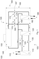
- the refrigeration system 100 includes a compressor refrigerant system 105.
- the refrigeration system 100 is configured to cool a target fluid to a target temperature.
- the target fluid is cooled with a useful cooling capacity 115 of the refrigeration system.
- the target fluid can be cooled to a target temperature between -80°C and +30°C, in particular to -40°C.
- the target fluid may be hydrogen in embodiments.
- the compressor refrigerant system includes a target heat exchanger 110.
- the target heat exchanger 110 is connected to the compressor refrigerant system on the cold side. On the cold side, a compressor refrigerant from the compressor refrigerant system flows through the target heat exchanger.
- the target heat exchanger 110 is connected to the system to be cooled on the warm side. The target fluid of the system to be cooled flows through the target heat exchanger 110 on the warm side. In the target heat exchanger, the compressor refrigerant absorbs thermal energy from the target fluid.
- the refrigeration system 100 includes an intermediate heat exchanger 120.
- the intermediate heat exchanger 120 is connected on the warm side to the compressor refrigerant system 105 and the compressor refrigerant flows through it.
- the intermediate heat exchanger 120 is connected to a natural circulation refrigerant system 140 and a natural circulation refrigerant flows through it.
- the compressor refrigerant releases heat energy to the natural circulation refrigerant in the intermediate heat exchanger 120 and condenses.
- the compressor refrigerant system includes a compressor 125 downstream of the target heat exchanger, which compresses the compressor refrigerant after receiving thermal energy of the target fluid in the intermediate heat exchanger.
- a pressure sensor 130 is disposed downstream of the compressor 125 and detects a pressure of the compressor refrigerant. The data from the pressure sensor 130 can be read out electronically; in particular, the pressure sensor 130 can be integrated into a control loop.
- a throttle valve 135 is arranged downstream of the intermediate heat exchanger.
- the compressor refrigerant is liquefied in the intermediate heat exchanger and passes to the throttle valve 135, which injects the compressor refrigerant into the target heat exchanger where it expands.
- the compressor refrigerant can absorb thermal energy from the target fluid.
- the natural circulation refrigerant system 140 includes the intermediate heat exchanger 120 which thermally connects the compressor refrigerant system and the natural circulation refrigerant system 140.
- the compressor refrigerant and the natural circulation refrigerant are spatially separated and are not mixed.
- the natural circulation refrigerant system 140 is designed to release the thermal energy that the natural circulation refrigerant absorbs in the intermediate heat exchanger 120 to the environment.
- the natural circulation refrigerant system 140 includes an ambient air condenser 145 upstream of the intermediate heat exchanger 120, which cools and liquefies the natural circulation refrigerant using ambient air. Natural circulation refrigerant, which has been cooled and liquefied in the ambient air condenser, can be injected into the intermediate heat exchanger.
- the ambient air condenser 145 includes a fan 150 to control a cooling capacity of the ambient air condenser 145.
- a control valve 165 is arranged downstream of the ambient air condenser 145 to control a mass flow of the natural circulation refrigerant into the intermediate heat exchanger 120.
- the control valve 165 can be controlled via a control unit 175 and an actuator 170.
- the actuator 170 can be controlled by the control unit 175 and control an opening degree of the control valve 165.
- An exchange heat that can be transferred from the compressor refrigerant to the natural circulation refrigerant in the intermediate heat exchanger is limited by the mass flow of the natural circulation refrigerant into the intermediate heat exchanger.
- a condensation pressure of the compressor refrigerant describes the pressure at which the compressor refrigerant is liquefied in the intermediate heat exchanger.
- the condensation pressure of the compressor refrigerant can be controlled via the Exchange heat can be controlled.
- the condensation pressure of the compressor refrigerant can be controlled via a mass flow of the natural circulation refrigerant into the intermediate heat exchanger.
- the condensation pressure of the compressor refrigerant can be influenced via the control valve, in particular via an opening degree of the control valve.
- the pressure sensor 130 can be connected to the control unit 175 in a control loop.
- the control unit 175 can regulate the degree of opening of the control valve 165 depending on the data from the pressure sensor 130, in particular in order to keep the condensation pressure as constant as possible at a target condensation pressure, which is specified to the control circuit.
- a shunt refrigerant system 160 is integrally connected to or integrated into the natural circulation refrigerant system 140.
- the refrigerant in the shunt refrigerant system is the same refrigerant as in the natural circulation refrigerant system, that is, it is the natural circulation refrigerant.
- the shunt refrigerant system includes a shunt control valve 165 located downstream of the ambient air condenser.
- a mass flow of the natural circulation refrigerant into the shunt refrigerant system 160 can be controlled via the shunt control valve 167 or its degree of opening by means of a shunt actuator 172.
- the control unit 175 controls the shunt actuator 172.
- the shunt refrigerant system uses the ambient air condenser 145.
- the target fluid is cooled with a shunt cooling capacity 185 of the refrigeration system.
- the shunt refrigerant system 160 includes a shunt heat exchanger 180, through which the natural circulation refrigerant flows on the cold side.
- the shunt heat exchanger 180 is connected to the system to be cooled on the warm side.
- the natural circulation refrigerant absorbs thermal energy from the target fluid.
- the natural circulation refrigerant which has absorbed 180 heat energy from the target fluid in the shunt heat exchanger, is liquefied in the ambient air condenser.
- the natural circulation refrigerant system 140 can be designed or operated without a compressor or pump.
- the height difference 190 between the intermediate heat exchanger 120 and the ambient air condenser 145 is 0.5 m or more, typically 1 m or more. This creates a thermosyphon in the natural circulation refrigerant system.
- the shunt height difference 195 between the The shunt heat exchanger 180 and the ambient air condenser 145 is 1 m, but can also be larger. This creates a thermosiphon in the shunt refrigerant system 160.
- the height differences between the respective upper connections or the respective lower connections of the respective heat exchangers are measured.
- FIG. 2 A method for cooling a target fluid using a refrigeration system as described herein is presented.
- a method for cooling the target fluid via the compressor refrigerant system is presented.
- step 210 the refrigeration system is started. To do this, the shunt control valve and the control valve are closed and the compressor is started.
- the intermediate heat exchanger is not flowed through by the natural circulation refrigerant and is quickly heated by the compressed compressor refrigerant. Heating the intermediate heat exchanger increases the condensation pressure of the compressor refrigerant.
- the control valve is opened and by controlling the exchange heat released in the intermediate heat exchanger, the condensation pressure of the compressor refrigerant is controlled to the target condensation pressure.
- the refrigeration system is in operation. If there is a requirement to increase a useful cooling capacity of the refrigeration system, in typical embodiments the throttle valve can be opened further so that more compressor refrigerant is injected into the target heat exchanger. In order to inject more compressor refrigerant into the target heat exchanger, more compressor refrigerant must be liquefied in the intermediate heat exchanger. To liquefy the additional compressor refrigerant in the intermediate heat exchanger, an opening degree of the control valve may be increased in typical embodiments to promote more natural circulation refrigerant through the intermediate heat exchanger. The compressor refrigerant can then release more exchange heat to the natural circulation refrigerant.
- a requirement to increase or decrease the useful cooling performance arises from a control that monitors the temperature of the target fluid after it flows through the target heat exchanger.
- the natural circulation refrigerant can release more exchange heat to the ambient air by switching on the fan of the ambient air condenser.
- the natural circulation refrigerant can absorb more exchange heat from the compressor refrigerant.
- the speed of the fan is controlled depending on the condensation pressure in order to increase or decrease the amount of exchange heat released in accordance with a requested useful cooling capacity.
- the control valve can be opened further or opened completely (step 240). More natural circulation refrigerant flows into the intermediate heat exchanger. The compressor refrigerant can release more exchange heat to the natural circulation refrigerant. The exchange heat is maximized. The useful cooling capacity of the refrigeration system is maximized.
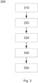
- FIG. 3 A method for cooling a target fluid using a refrigeration system as described herein is presented.
- a method for cooling the target fluid via the shunt refrigerant system is presented.
- step 310 it is checked whether free cooling is possible via the shunt refrigerant system. For this purpose, it is checked whether the ambient temperature of the ambient air is below the target temperature and, if so, a temperature difference between the target temperature of the target fluid and the ambient temperature of the ambient air is compared with a limit temperature difference. If the temperature difference exceeds the limit temperature difference, cooling is possible via the shunt refrigerant system.
- the refrigeration system is switched to cooling via the shunt refrigerant system in step 320.
- the control valve is closed and the shunt control valve will be opened.
- the natural circulation refrigerant flows through the shunt heat exchanger and absorbs shunt exchange heat from the target fluid.
- the target fluid is cooled.
- the shunt cooling capacity depends on the shunt exchange heat.
- the refrigeration system is in operation. If there is a requirement to increase a shunt cooling capacity of the refrigeration system, in typical embodiments an opening degree of the shunt control valve may be increased so that more natural circulation refrigerant is conveyed through the shunt heat exchanger. The target fluid can release more exchange heat to the natural circulation refrigerant.
- the natural circulation refrigerant can release more exchange heat to an ambient air by switching on a fan of an ambient air condenser.
- the natural circulation refrigerant can absorb more exchange heat from the target fluid.
- the speed of the fan is typically controlled depending on the condensation pressure to increase or decrease the amount of exchange heat released according to a requested shunt cooling capacity.
- the shunt control valve can be opened further when the fan is operating at maximum.
- the shunt control valve can be opened completely. More natural circulation refrigerant flows into the shunt heat exchanger.
- the target fluid can release more exchange heat to the natural circulation refrigerant.
- the exchange heat is maximized.
- the shunt cooling capacity of the refrigeration system is maximized.
Landscapes
- Engineering & Computer Science (AREA)
- Mechanical Engineering (AREA)
- General Engineering & Computer Science (AREA)
- Physics & Mathematics (AREA)
- Thermal Sciences (AREA)
- Air Conditioning Control Device (AREA)
Applications Claiming Priority (1)
| Application Number | Priority Date | Filing Date | Title |
|---|---|---|---|
| DE102022122589.5A DE102022122589A1 (de) | 2022-09-06 | 2022-09-06 | Kälteanlage und Verfahren zum Betreiben einer Kälteanlage |
Publications (1)
| Publication Number | Publication Date |
|---|---|
| EP4336126A1 true EP4336126A1 (fr) | 2024-03-13 |
Family
ID=87930122
Family Applications (1)
| Application Number | Title | Priority Date | Filing Date |
|---|---|---|---|
| EP23195128.6A Withdrawn EP4336126A1 (fr) | 2022-09-06 | 2023-09-04 | Installation frigorifique et procédé de fonctionnement d'une installation frigorifique |
Country Status (3)
| Country | Link |
|---|---|
| US (1) | US20240077235A1 (fr) |
| EP (1) | EP4336126A1 (fr) |
| DE (1) | DE102022122589A1 (fr) |
Citations (2)
| Publication number | Priority date | Publication date | Assignee | Title |
|---|---|---|---|---|
| US20190293326A1 (en) * | 2016-05-25 | 2019-09-26 | Marwan Chamoun | Air and water cooled chiller for free cooling applications |
| DE112018005735T5 (de) * | 2017-11-01 | 2020-07-23 | Denso Corporation | Anlagenkühlungsvorrichtung |
Family Cites Families (3)
| Publication number | Priority date | Publication date | Assignee | Title |
|---|---|---|---|---|
| DE4242848C2 (de) | 1992-12-18 | 1994-10-06 | Danfoss As | Kälteanlage und Verfahren zur Steuerung einer Kälteanlage |
| JPH11257762A (ja) | 1998-03-12 | 1999-09-24 | Denso Corp | 冷凍サイクル装置 |
| JP6423736B2 (ja) | 2015-02-17 | 2018-11-14 | オーム電機株式会社 | 冷却装置 |
-
2022
- 2022-09-06 DE DE102022122589.5A patent/DE102022122589A1/de active Pending
-
2023
- 2023-09-01 US US18/241,562 patent/US20240077235A1/en not_active Abandoned
- 2023-09-04 EP EP23195128.6A patent/EP4336126A1/fr not_active Withdrawn
Patent Citations (2)
| Publication number | Priority date | Publication date | Assignee | Title |
|---|---|---|---|---|
| US20190293326A1 (en) * | 2016-05-25 | 2019-09-26 | Marwan Chamoun | Air and water cooled chiller for free cooling applications |
| DE112018005735T5 (de) * | 2017-11-01 | 2020-07-23 | Denso Corporation | Anlagenkühlungsvorrichtung |
Also Published As
| Publication number | Publication date |
|---|---|
| DE102022122589A1 (de) | 2024-03-07 |
| US20240077235A1 (en) | 2024-03-07 |
Similar Documents
| Publication | Publication Date | Title |
|---|---|---|
| DE19955339B4 (de) | Heißwasserversorgungssystem | |
| EP0701096B1 (fr) | Procédé de fonctionnement d'une installation productrice de froid pour la climatisation de véhicules et installation productrice de froid pour sa mise en oeuvre | |
| EP1264715B1 (fr) | Système de refroidissement d'un véhicule pour un dispositif d'augmentation de la température et méthode pour le refroidissement du dispositif d'augmentation de la température | |
| EP1262347B1 (fr) | Circuit de chauffage/réfrigération pour un climatiseur de véhicule à moteur, climatiseur et procédé pour sa commande | |
| DE102018209769A1 (de) | Verfahren zum Betreiben einer einen Kältemittelkreislauf aufweisenden Kälteanlage eines Fahrzeugs | |
| DE4324510A1 (de) | Verfahren und Vorrichtung zum Betreiben eines Kühlsystems | |
| EP3816543B1 (fr) | Procédé de régulation d'un détendeur | |
| EP1215452B1 (fr) | Appareil frigorifique avec régulation de la température de surchauffe à l'avant du compresseur | |
| DE102019201427B4 (de) | Verfahren zum Betreiben eines Kältemittelkreislaufs einer Kälteanlage eines Fahrzeugs | |
| DE19500867A1 (de) | Verfahren und Vorrichtung zum Betreiben eines Kälteerzeugungssystems | |
| EP3702181B1 (fr) | Pompe à chaleur à régulation partielle de la charge | |
| DE102018113687B4 (de) | Vorrichtung und Verfahren zur Kühlung von Batteriezellenmodulen | |
| EP4160109A1 (fr) | Système de refroidissement et appareil de laboratoire doté d'un système de refroidissement | |
| DE3821910C2 (fr) | ||
| DE102017213973A1 (de) | Verfahren zum Betreiben einer Kälteanlage eines Fahrzeugs mit einem eine Kühl- und Heizfunktion aufweisenden Kältemittelkreislauf | |
| EP3922932B1 (fr) | Procédé de fonctionnement d'une installation de réfrigération à compression et installation de réfrigération à compression | |
| EP3640565A1 (fr) | Régulation de la puissance optimale cop | |
| EP1350068B1 (fr) | Procede pour reguler un appareil de refroidissement | |
| EP0239837A2 (fr) | Procédé pour la récupération de la chaleur de condensation d'un système frigorifique et système frigorifique pour la mise en oeuvre du procédé | |
| EP4336126A1 (fr) | Installation frigorifique et procédé de fonctionnement d'une installation frigorifique | |
| DE19829335C2 (de) | Kälteanlage | |
| DE102019135468A1 (de) | Verfahren zum Betrieb eines integralen Heiz-/Klimatisierungs- und Kühlsystems sowie integrales Heiz-/Klimatisierungs- und Kühlsystem mit thermischem Speicher | |
| DE102020115274A1 (de) | Verfahren zum Betrieb einer Kompressionskälteanlage | |
| WO2004055454A1 (fr) | Circuit de refrigerant pour une installation de climatisation de vehicule automobile | |
| DE10342110A1 (de) | Kältemittel-Kreislauf für eine Kraftfahrzeug-Klimaanlage, Kraftfahrzeug-Klimaanlage und Verfahren zum Betreiben einer solchen |
Legal Events
| Date | Code | Title | Description |
|---|---|---|---|
| PUAI | Public reference made under article 153(3) epc to a published international application that has entered the european phase |
Free format text: ORIGINAL CODE: 0009012 |
|
| STAA | Information on the status of an ep patent application or granted ep patent |
Free format text: STATUS: THE APPLICATION HAS BEEN PUBLISHED |
|
| AK | Designated contracting states |
Kind code of ref document: A1 Designated state(s): AL AT BE BG CH CY CZ DE DK EE ES FI FR GB GR HR HU IE IS IT LI LT LU LV MC ME MK MT NL NO PL PT RO RS SE SI SK SM TR |
|
| STAA | Information on the status of an ep patent application or granted ep patent |
Free format text: STATUS: REQUEST FOR EXAMINATION WAS MADE |
|
| 17P | Request for examination filed |
Effective date: 20240912 |
|
| RBV | Designated contracting states (corrected) |
Designated state(s): AL AT BE BG CH CY CZ DE DK EE ES FI FR GB GR HR HU IE IS IT LI LT LU LV MC ME MK MT NL NO PL PT RO RS SE SI SK SM TR |
|
| STAA | Information on the status of an ep patent application or granted ep patent |
Free format text: STATUS: THE APPLICATION HAS BEEN WITHDRAWN |
|
| 18W | Application withdrawn |
Effective date: 20251002 |