EP4336162A1 - Multidirektionales detektorsystem mit offenem weg und verfahren zur verwendung davon - Google Patents
Multidirektionales detektorsystem mit offenem weg und verfahren zur verwendung davon Download PDFInfo
- Publication number
- EP4336162A1 EP4336162A1 EP23189732.3A EP23189732A EP4336162A1 EP 4336162 A1 EP4336162 A1 EP 4336162A1 EP 23189732 A EP23189732 A EP 23189732A EP 4336162 A1 EP4336162 A1 EP 4336162A1
- Authority
- EP
- European Patent Office
- Prior art keywords
- detector
- transmitter
- reflector
- optical element
- receiver
- Prior art date
- Legal status (The legal status is an assumption and is not a legal conclusion. Google has not performed a legal analysis and makes no representation as to the accuracy of the status listed.)
- Pending
Links
Images


Classifications
-
- G—PHYSICS
- G01—MEASURING; TESTING
- G01M—TESTING STATIC OR DYNAMIC BALANCE OF MACHINES OR STRUCTURES; TESTING OF STRUCTURES OR APPARATUS, NOT OTHERWISE PROVIDED FOR
- G01M3/00—Investigating fluid-tightness of structures
- G01M3/02—Investigating fluid-tightness of structures by using fluid or vacuum
- G01M3/04—Investigating fluid-tightness of structures by using fluid or vacuum by detecting the presence of fluid at the leakage point
-
- F—MECHANICAL ENGINEERING; LIGHTING; HEATING; WEAPONS; BLASTING
- F17—STORING OR DISTRIBUTING GASES OR LIQUIDS
- F17D—PIPE-LINE SYSTEMS; PIPE-LINES
- F17D5/00—Protection or supervision of installations
- F17D5/005—Protection or supervision of installations of gas pipelines, e.g. alarm
-
- F—MECHANICAL ENGINEERING; LIGHTING; HEATING; WEAPONS; BLASTING
- F17—STORING OR DISTRIBUTING GASES OR LIQUIDS
- F17D—PIPE-LINE SYSTEMS; PIPE-LINES
- F17D5/00—Protection or supervision of installations
- F17D5/02—Preventing, monitoring, or locating loss
-
- G—PHYSICS
- G01—MEASURING; TESTING
- G01M—TESTING STATIC OR DYNAMIC BALANCE OF MACHINES OR STRUCTURES; TESTING OF STRUCTURES OR APPARATUS, NOT OTHERWISE PROVIDED FOR
- G01M3/00—Investigating fluid-tightness of structures
- G01M3/38—Investigating fluid-tightness of structures by using light
-
- G—PHYSICS
- G01—MEASURING; TESTING
- G01N—INVESTIGATING OR ANALYSING MATERIALS BY DETERMINING THEIR CHEMICAL OR PHYSICAL PROPERTIES
- G01N21/00—Investigating or analysing materials by the use of optical means, i.e. using sub-millimetre waves, infrared, visible or ultraviolet light
- G01N21/01—Arrangements or apparatus for facilitating the optical investigation
-
- G—PHYSICS
- G01—MEASURING; TESTING
- G01N—INVESTIGATING OR ANALYSING MATERIALS BY DETERMINING THEIR CHEMICAL OR PHYSICAL PROPERTIES
- G01N21/00—Investigating or analysing materials by the use of optical means, i.e. using sub-millimetre waves, infrared, visible or ultraviolet light
- G01N21/17—Systems in which incident light is modified in accordance with the properties of the material investigated
- G01N21/25—Colour; Spectral properties, i.e. comparison of effect of material on the light at two or more different wavelengths or wavelength bands
- G01N21/31—Investigating relative effect of material at wavelengths characteristic of specific elements or molecules, e.g. atomic absorption spectrometry
- G01N21/35—Investigating relative effect of material at wavelengths characteristic of specific elements or molecules, e.g. atomic absorption spectrometry using infrared light
- G01N21/3504—Investigating relative effect of material at wavelengths characteristic of specific elements or molecules, e.g. atomic absorption spectrometry using infrared light for analysing gases, e.g. multi-gas analysis
- G01N21/3518—Devices using gas filter correlation techniques; Devices using gas pressure modulation techniques
Definitions
- Various embodiments described herein relate generally to detector systems for detecting the presence of a gas in an area, and more particularly to an open path detector system.
- Open path detector systems are generally used today to determine the presence of a gas (e.g., hazardous gas) due to leak in various environments, for example, a pipeline environment.
- a gas e.g., hazardous gas
- an open path detector system may be used to monitor the presence of a gas in an area based at least in part on attenuation in emitted radiation.
- Various embodiments described herein relate to multi-directional open path detector systems and methods for using the same.
- Various embodiments are directed to a multi-directional open path detector system comprising: a plurality of transmitters, wherein each transmitter is configured to emit a beam signal in a beam path, and wherein each beam path direction is different for each transmitter of the plurality of transmitters; a receiver at a receiver location, wherein the receiver is positioned in the beam path for each transmitter of the plurality of transmitters and configured to receive, for each transmitter, an incoming beam corresponding to the emitted beam signal by the respective transmitter, the receiver comprising: an optical element; at least one detector; and a reflector element in reflective communication with the optical element, wherein for each transmitter: the reflector element is configured to direct the incoming beam towards the optical element, the optical element is configured to redirect the incoming beam towards the at least one detector, and the at least one detector is configured to generate an output signal based at least in part on the incoming beam; and the multi-directional open path detector system further comprises a
- the plurality of transmitters may be spaced circumferentially around the receiver.
- the reflector element may comprise a plurality of reflector faces, wherein each transmitter of the plurality of transmitters is aligned with a reflector face of the plurality of reflector faces, and wherein each reflector face is configured to direct the incoming beam from the corresponding transmitter to the optical element.
- the reflector element may comprise a pyramid shape.
- the optical element may comprise a concave mirror.
- the optical element may comprise a flat mirror.
- the plurality of transmitters may be configured to emit the beam signals in a sequential order.
- the receiver may further comprise a beam splitter communicably coupled to the optical element, wherein the beam splitter is configured to split each incoming beam that is redirected towards the at least one detector into a first incoming beam portion and a second incoming beam portion.
- the at least one detector may comprise a first detector and a second detector, wherein the first detector is configured to receive a first incoming beam portion having a first wavelength and the second detector is configured to receive a second incoming beam portion having a second wavelength.
- the beam path between the receiver and each transmitter may be a straight beam path.
- the beam signal emitted by each transmitter may comprise infrared radiation.
- the output signal generated by the at least one detector may comprise an intensity measure.
- the controller may be configured for wireless communication of the detection signal to one or more external devices.
- a receiver for a multi-directional open path detector comprising: at least one detector; a controller communicably coupled to the at least one detector; an optical element; and a reflector element in reflective communication with the optical element, wherein: the reflector element is configured to direct incoming beam from a transmitter towards the optical element; the optical element is configured to redirect the incoming beam towards the at least one detector; the at least one detector is configured to generate an output signal based at least in part on the incoming beam; and the controller is configured to generate a detection signal based at least in part on the output signal, wherein the detection signal may be indicative of presence of a detected gas.
- the reflector element may comprise a plurality of reflector faces, wherein each reflector face is configured for being aligned with a transmitter of a plurality of transmitters, and wherein each reflector face is configured to direct the incoming beam from the corresponding transmitter to the at least one detector.
- the reflector element may comprise a pyramid shape.
- the optical element may comprise a concave mirror. In various embodiments, the optical element may comprise a flat mirror.
- Various embodiments are directed to a method for detecting gas in a region, the method comprising: aligning a receiver with a plurality of transmitters; receiving incoming beam from each transmitter of the plurality of transmitters; for each transmitter: redirecting the received incoming beam; and generating a detection signal based at least in part on the redirected incoming beam.
- each incoming beam is received sequentially.
- each received incoming beam is redirected towards at least one detector.
- the incoming beam received from each transmitter may comprise infrared radiation.
- the method may further comprise communicating one or more detection signals to one or more external devices.
- a device configured to detect the presence of a gas or gases (e.g., target gas(es)) in an area.
- a gas or gases e.g., target gas(es)
- various applications may produce, transport, and/or store gas(es) that pose severe environmental and health risks if leaked to the environment undetected.
- Various gas detector systems may utilize a receiver and a transmitter to detect the presence of target gases based at least in part on the interaction of these gases with a radiation signal traveling through a beam path between the transmitter and receiver.
- a gas detector system configured to utilize a receiver and a transmitter to facilitate the determination of the presence of a gas in an area, particularly a large area, may be subject to system inaccuracies caused by a narrow field of view.
- emitted radiation incident on a receiver may not pass through a target gas (e.g., leaked gas) in a monitored area due at least in part to the narrow field of view of the receiver, thus resulting in inaccurate detection.
- target gas e.g., leaked gas
- various implementations utilizing multiple receivers and transmitters may be constrained by various variables, including, but not limited to, installation space, increased cost, and increased process and power consumption. Accordingly, a need exists for a gas detection system that is able to efficiently and accurately determine the presence of target gases in an area.
- an exemplary multi-directional open path detector system configured to provide multi-path detection that at least efficiently compensates for narrow field of view of receivers, and thus enables a more accurate gas detection.
- An exemplary multi-directional open path detector system may comprise a receiver configured to provide a multi-field view, wherein the presence of target gas(es) in an area may be detected based at least in part on radiation beams incident on the receiver from different directions in the monitored area, thus covering/spanning a larger portion of the area.
- an exemplary multi-directional open path detector system may be configured to detect the presence of target gas(es) based at least in part on a determined/measured attenuation in signal intensity of a radiation beam incident on the receiver due to the interference of target gas(es) with the signal.
- a volume of gas e.g., target gas
- certain wavelength(s) may be absorbed by the gas resulting in reduced signal intensity.
- an exemplary multi-directional open path detector system of the present invention may be configured to measure the intensity of radiation beams incident on the receiver from multiple directions to determine attenuation in intensity (if any), and may be configured to determine the presence of target gas(es) based at least in part on the determined attenuation in intensity.
- an exemplary receiver as described herein may comprise one or more detectors and a reflector element having a plurality of reflector faces (e.g., receiving faces).
- the reflector faces may be configured to collect and direct, in conjunction with one or more optical elements, radiation beams (e.g., infrared (IR) radiation beam, light beam, and/or the like) incident on the respective reflector faces towards at least one detector.
- the incident radiation beams may be emitted from a plurality of transmitters that are each positioned at a distance from the receiver, wherein the receiver is positioned in a beam path for each transmitter of the plurality of transmitters.
- the transmitters may be positioned at different locations (e.g., receiver location) in the monitored area so as to enable emission of radiation beams from different directions (e.g., different beam path directions).
- the transmitters may be arranged, oriented, and/or distributed in different configurations relative to one another and/or the receiver. In various embodiments, the distance, arrangement, orientation, and/or distribution of the transmitters may be based at least in part on the configuration of the reflector faces of the reflector element.
- An exemplary transmitter as described herein may be configured to emit radiation (e.g., infrared (IR), light, and/or the like) having at least a wavelength that is absorbed by a target gas.
- IR infrared
- incoming radiation beams corresponding to emitted radiation beam signals may be received (e.g. incident) on the reflector faces of the reflector element in a sequential manner.
- emission of radiation signals by the transmitters may be time-delayed so as to enable sequential emission.
- the plurality of reflector faces may be configured to direct the sequentially incident incoming radiation beams to at least one detector via one or more optical elements.
- each reflector face may be communicably coupled to (e.g., in reflective communication with) an optical element that is configured to receive incoming radiation beams reflected from the reflector face and redirect the received incoming radiation beam to the at least one detector.
- each reflector face may be communicably coupled to a single optical element.
- a subset of the reflector faces may be communicably coupled to a particular optical element of a plurality of optical elements.
- the at least one detector may be configured to generate, for each received incoming radiation beam, an output signal.
- the output signal may represent a signal intensity (e.g., signal strength) for the respective received incoming radiation beam.
- the incoming radiation beams incident on the reflector faces are directed to a set of detectors and each detector in the set of detectors may be configured to generate an output signal (e.g., intensity/signal strength) for a respective incoming radiation beam.
- the generated output signals may be further analyzed and/or processed to generate a detection signal that is indicative of the presence or absence of a target gas (e.g., detected gas).
- the above described configurations according to various embodiments of the present invention enable a more accurate gas detection based on a multi-field view, while simultaneously reducing installation cost, equipment cost, process and power consumption, and space utilization. Further, at least in part because of the efficient space utilization (e.g., utilization of a single receiver as opposed to multiple receivers), various embodiments of the exemplary multi-directional open path detection system of the present invention may be utilized in areas constrained by space, thus enabling a more accurate detection in these noted areas.
- the set of detectors may comprise a first detector and a second detector that are each configured to receive a portion of an incoming radiation beam incident on a reflector face of the reflector.
- a beam splitter may be utilized to split each incoming radiation beam into a first radiation beam portion and a second radiation beam portion such that the first radiation beam portion is directed towards the first detector and the second radiation beam portion is directed towards the second detector.
- Each detector may be configured to receive a radiation beam portion having a particular wavelength, and may be configured to generate for the received radiation beam portion an output signal, where the output signal may correspond to the intensity of the radiation beam at the particular wavelength.
- the first detector may be configured to generate a first output signal corresponding to the intensity (e.g., intensity measure) of an incoming radiation beam at a first wavelength (e.g., sample wavelength at which a target gas absorbs the radiation), while the second detector may be configured to generate a second output signal corresponding to the intensity (e.g., intensity measure) of the same incoming radiation beam at a second wavelength (reference wavelength at which the target gas does not absorb the radiation).
- a first output signal corresponding to the intensity (e.g., intensity measure) of an incoming radiation beam at a first wavelength (e.g., sample wavelength at which a target gas absorbs the radiation)
- a second detector may be configured to generate a second output signal corresponding to the intensity (e.g., intensity measure) of the same incoming radiation beam at a second wavelength (reference wavelength at which the target gas does not absorb the radiation).
- an exemplary detector as described herein may comprise one or more optical filters (e.g., bandpass filters, low pass filter, high pass filter, and/or the like) configured to allow the desired wavelength to pass through so as to enable measurement of the intensity of the signal at the desired wavelength.
- the first detector may include a first optical filter configured to allow the sample wavelength to pass through and the second detector may include a second optical filter configured to allow the reference wavelength to pass through.
- the beam splitter may be configured to split each incoming radiation beam into a first radiation beam portion having the first wavelength (e.g., sample wavelength) and a second radiation beam portion having the second wavelength (e.g., reference wavelength) such that the detectors may not comprise and/or require optical filters.
- a controller communicably coupled to the receiver and/or detectors may be configured to generate, based at least in part on the output signals from each detector, a detection signal that is indicative of the presence or absence of target gas(es) in the corresponding path.
- the controller may be configured to generate the detection signal for a particular incoming radiation beam incident on the receiver based at least in part on comparing the output signals from the first and second detectors for the particular incoming radiation beam, where a lower intensity at the sample wavelength relative to the reference wavelength may be indicative of the presence of a target gas.
- the controller may be configured to generate the detection signal for an incoming radiation beam based at least in part on determining (e.g., calculating) the difference between the output signals (e.g., difference measure) and determining whether the difference measure satisfies a difference measure threshold, where a difference measure that satisfies the difference measure threshold may be indicative of the presence of target gas(es).
- the controller may be configured to generate the detection signal for an incoming radiation beam signal based at least in part on determining (e.g., calculating) a ratio of the intensity of the incoming radiation beam at the sample wavelength to the intensity of the incoming radiation beam at the reference wavelength (e.g., ratio measure) and determining whether the ratio measure satisfies a ratio measure threshold, where a ratio measure that satisfies the ratio measure threshold may be indicative of the presence of target gas(es).
- an exemplary multi-directional open path detector system 1 may comprise a receiver 2 and one or more transmitters 3, and may be configured to detect the presence of a gas (e.g., flammable and/or toxic gas(es)) in an area.
- a gas e.g., flammable and/or toxic gas(es)
- an exemplary multi-directional open path detector system 1 may comprise a receiver 2 and a plurality of transmitters 3 configured to detect the presence of a gas along a plurality of beam paths defined by the receiver 2 and the plurality of transmitters 3.
- the beam path may be a straight beam path between the receiver 2 and a corresponding transmitter 3.
- each transmitter 3 may comprise a radiation source (e.g., light emitting diodes (LED), laser diode, arc lamp, infrared radiation source, and/or the like) configured to emit radiation beam signals (e.g., collimated radiation beams) along a beam path.
- a radiation source e.g., light emitting diodes (LED), laser diode, arc lamp, infrared radiation source, and/or the like
- each transmitter 3 may define an emitting face 32 through which one or more signals may be emitted by the transmitter 3.
- transmitter 3 e.g., radiation source thereof
- the wavelength(s) of the radiation emitted by a transmitter 3 may be selected such that the radiation comprises at least a particular wavelength (e.g., sample wavelength that would be absorbed by the target gas(es)).
- transmitter 3 e.g., radiation source thereof
- transmitter 3 may be configured to emit radiation beam signals having at least a first wavelength (sample wavelength that would be absorbed by the target gas(es)) and a second wavelength (reference wavelength that would not be absorbed by the target gas(es)).
- An exemplary transmitter 3 may include a housing 34 configured to house the radiation source and/or one or more other components (not shown) such as optical components, internal controllers, and/or the like.
- the one or more transmitters 3 may be configured to emit a signal (e.g., infrared radiation signal) along a beam path towards the receiver 2.
- each transmitter 3 may include one or more internal controllers and/or circuitry (not shown) configured to control one or more function(s) and/or operation parameters of the respective transmitter 3.
- the one or more internal controllers e.g., transmitter internal controllers and/or circuitry
- the one or more transmitter internal controllers and/or circuitry may be configured to communicate (e.g., wirelessly) with controller 100 (described further below).
- each transmitter 3 e.g., internal controller and/or circuitry thereof
- the drive signal may be generated and transmitted by the receiver 2 (e.g., a controller and/or circuitry thereof). In some embodiments, the driver signal may not be generated and/or transmitted by the receiver 2. In various embodiments, the drive signal may be generated by a controller such as controller 100.
- the transmitters 3 may be arranged in a variety of configurations (e.g., based at least in part on the receiver configuration, the application, and/or the monitored area). Each transmitter 3 may be positioned at a location (e.g., receiver location) within a monitored area and/or vicinity of a monitored area. As a non-limiting example, as shown in Figure 1 , the plurality of transmitters 3 may be spaced circumferentially around the receiver 2.
- Figure 2 schematically illustrates an exemplary receiver 2 according to various embodiments of the present invention
- Figure 3 illustrates a close-up view of the receiver 2.
- the receiver 2 may comprise a reflector element 20, an optical element 30, and a detector set (e.g., detectors 52, 54) configured to receive incoming radiation beam signals (incoming radiation beams) 36 from each of the transmitters 3, wherein an incoming radiation beam signal 36 may describe an emitted radiation beam signal incident on the reflector element 20, wherein the emitted radiation beam signal may comprise collimated radiation beam.
- the reflector element 20 may be communicably coupled to the optical element 30 and may be configured to direct incoming beam signals (incoming beam) to the detector via reflective communication with the optical element 30.
- the optical element 30 may be communicably coupled to a beam splitter and/or at least one detector (e.g., detector 52, detector 54).
- the reflector element 20 may comprise a plurality of reflector faces 24.
- a reflector face 24 may be substantially flat. Additionally and/or alternatively in various other embodiments, the reflector face may comprise a curved portion.
- a reflector face 24 may comprise a mirror (e.g., a lens) configured to reflect incoming radiation beams towards the optical element 30.
- each reflector face 24 is a mirror face or otherwise comprise a mirror face.
- the reflector face may comprise any optical component suitable to reflect incoming radiation beam towards the optical element 30.
- the shape, angle of inclination, and/or angle of curvature of a reflector face 24 may be selected such that an incoming radiation beam incident on the reflector face 24 is reflected (e.g., directed) towards the optical element 30.
- the angle of incidence of an incoming radiation beam on a reflector face may be selected such that the incoming radiation beam is reflected towards the optical element 30.
- the source of the incoming radiation beam e.g., transmitter
- the source of the incoming radiation beam may be configured to emit radiation beams at an angle (e.g., 30°, 45°, 70°, and/or the like), such that when the radiation beam incidents on a reflector face 24 (e.g., at a desired/selected angle of incidence as noted above), the radiation beam is directed towards the optical element 30.
- each reflector face 24 may be configured such that it may receive radiation beam signals emitted by a transmitter 3 at a receiver location.
- the reflector element 20 may be configured such that the plurality of reflector faces 24 may be aligned with the plurality of transmitters 3 (e.g., emitting face 32 thereof), wherein each reflector face 24 is aligned with a different transmitter 3.
- the reflector element 20 may be configured such that the plurality of transmitters 3 may be spaced, arranged and/or distributed such that the emitting face 32 of each transmitter 3 faces a reflector face 24 of the plurality of reflector faces 24 of the reflector element 20.
- the reflector element 20 e.g., reflector faces 24 thereof
- each transmitter 3 and corresponding reflector face 24 may be arranged such that each transmitter 3 and corresponding reflector face 24 are at a distance from one another and maintain at least substantially horizontal configuration, wherein the emitted radiation beam may travel in a substantially horizontal plane.
- the one or more reflector faces 24 may be configured to receive incoming radiation beam signals at a variety of angles (e.g., 45 degrees, 60 degrees, and/or the like).
- the one or more transmitters 3 may be configured to emit radiation signals at a 45 degree angle, a 60 degree angle, and/or the like.
- the distance between an emitting face 32 of a transmitter 3 and a corresponding reflector face 24 can vary and may be of any suitable/desired distance (e.g., based at least in part on the application, the monitored environment, the type of transmitter, the components of the reflector element, and/or the like).
- the preferred distance between an emitting face 32 of a transmitter 3 and a corresponding reflector face 24 of a reflector element 20 is in the range of 10ft to 330ft. It should be understood, however, that in various embodiments, the distance between an emitting face 32 of a transmitter 3 and a corresponding reflector face 24 may be less than 10ft or greater than 330ft.
- reflector element 20 may define a plurality of sides, wherein one or more of the sides may comprise a reflector face 24.
- reflector element 20 may define at least a portion of a shape having a plurality of sides, wherein one or more sides of the plurality of sides may comprise a reflector face 24.
- the reflector element 20 may define at least a portion of a pyramid shape wherein each side comprises a reflector face 24.
- the reflector element 20 may define an opening 26, and may be configured to house one or more components of the receiver 2 (e.g., detectors 52, 54, beam splitter 60, and/or other components).
- Figure 3 depicts a reflector element 20 having a pyramid shape profile with four sides
- the reflector element 20 may comprise at least a portion of a pentagonal pyramid, a heptagonal pyramid, an octagonal pyramid, and/or the like.
- Figure 3 depicts a reflector element 20 having a pyramid shape
- various other embodiments of the present invention may comprise a reflector element 20 having other shape profiles.
- Figure 3 depicts a reflector element 20, wherein each of the sides of the reflector element 20 comprises a reflector face 24, in various other embodiments, one or more sides of the reflector element 20 may not comprise a reflector face.
- the reflector element 20 may define (e.g., comprise) a shape that is different from a pyramid shape.
- the reflector element 20 may be cone-shaped (not shown), such that the reflector element comprise a single reflector face spanning the entire surface (e.g., or substantially the entire surface) of the cone-shaped reflector element.
- the cone shape of the reflector element may enable positioning/locating transmitters anywhere with respect to the monitored area, such that incoming radiation beams from different directions may incident on the single reflector face of the cone-shaped reflector element at different areas thereof, and reflected towards the optical element 30.
- the optical element 30 may comprise a mirror (e.g., a lens) configured to redirect incoming radiation beam (e.g., collimated radiation beam) reflected from a reflector face 24, wherein redirecting an incoming radiation beam comprises converging the incoming collimated radiation beam at a desired focal point (e.g., at a detector).
- a mirror e.g., a lens
- redirecting an incoming radiation beam comprises converging the incoming collimated radiation beam at a desired focal point (e.g., at a detector).
- the shape, focal length, aperture, f-number, and/or other parameters/characteristics of the optical element 30 may be selected such that the optical element 30 converges/concentrates the incoming radiation beam to at least one detector (e.g., detector 52 and/or detector 54).
- the size of the receiver e.g., dimensions of the reflector faces
- the distance between the optical element 30 and the at least one detector, where the redirected radiation beams converge may be based at least in part on the f-number of the optical element (e.g., ratio of the focal length to the aperture).
- the optical element 30 may comprise a mirror (e.g., lens) having a concave shape (e.g., spherical, aspherical, complex, and/or the like) and may be positioned above relative to the reflector element 20 such that the concave-shaped mirror (e.g., concave mirror face) faces downwardly.
- a mirror e.g., lens
- concave shape e.g., spherical, aspherical, complex, and/or the like
- the reflector faces 24 may be configured to reflect incoming radiation beams in an upward direction at about 90 degrees relative to the incoming radiation beam
- the optical element 30 may be positioned above relative to the reflector element 20 with the concave mirror face 31 facing downwardly and at a focal length, aperture, and/or f-number that enables redirection (e.g., converging/concentration) of each incoming radiation beam reflected from each reflector face 24 of the reflector element 20 towards detector 52 and/or detector 54.
- the aperture e.g., a length (diameter) D of the reflecting concave mirror face
- the focal length of the concave mirror face of the optical element 30 may be selected such that each incoming radiation beam reflected from each reflector face 24 incidents on at least a portion of the concave mirror face of the optical element 30.
- the configuration of the receiver 2 e.g., the shape of the reflector element 20, the angle and/or profile of the reflector faces, the shape, aperture, and/or focal length of the optical element 30, and/or the like
- the optical element 30 is positioned above relative to the reflector element 20, in other embodiments, the optical element 30 may be positioned below relative to the reflector element 20 (e.g., the reflector element may comprise an upside down pyramid).
- the receiver 2 may include a beam splitter 60.
- the beam splitter may comprise a partially reflecting mirror and may be configured to split each radiation beam redirected from the optical element 30 into two portions.
- the beam splitter 60 may be positioned between the optical element 30 and at least one detector (e.g., detector 52), and may be configured to split each radiation beam redirected from the optical element 30 into a first radiation beam portion 36A (also referred to as first incoming beam portion) and a second radiation beam portion 36B (also referred to as second incoming beam portion) based at least in part on transmitting a portion of the radiation beam (e.g., corresponding to the first radiation beam portion 36A) and reflecting a portion of the radiation beam (e.g., corresponding to the second radiation beam portion 36B).
- the first radiation beam portion 36A comprises the reference wavelength and the second radiation beam portion 36B comprises the sample wavelength, or vice versa.
- the first radiation beam portion 36A comprises the sample wavelength
- the second radiation beam portion 36B comprises the reference wavelength.
- the orientation and/or location of each of the detectors 52, 54 and the beam splitter 60 relative to one another may be selected such that the first radiation beam portion 36A (e.g., transmitted portion) is directed to the first detector 52 and the second radiation beam portion 36B (e.g., reflected portion) is directed to the second detector 54.
- the beam splitter may comprise a dichroic beam splitter configured to split a radiation beam into a first radiation beam portion having the reference wavelength and a second radiation beam having the sample wavelength, or vice versa (as described above).
- the beam splitter may comprise a plate beam splitter, a cube beam splitter, and/or other suitable beam splitters.
- the beam splitter 60 and the detectors 52, 54 may be housed within a housing defined/formed by the reflector element 20.
- the optical element 30 may be configured to redirect the reflected incoming radiation beam signals (incoming radiation beam) from the reflector faces 24 of the reflector element 20 through the opening 26 defined by the reflector element housing.
- the beam splitter 60 and the detectors 52, 54 may not be located within the reflector element 20.
- the reflector element 20 may not define an opening and may not house the beam splitter 60 and/or the detectors 52, 54.
- the reflector element 20 may house one or more of the beam splitter 60, the first detector 52, or the second detector 54.
- one or more components of the receiver 2 may be supported using a mechanical mount, such as a spider mounting system.
- a mechanical mount such as a spider mounting system
- at least a portion of the mechanical mount is positioned between the optical element 30 and the reflector element 20.
- at least a portion of the mechanical mount is positioned within the reflector element 20.
- the beam splitter may be configured to split each radiation beam redirected from the optical element 30 into a first radiation beam portion 36A having a first wavelength (e.g., sample wavelength) and a second radiation beam portion 36B having a second wavelength (e.g., reference wavelength), or vice versa.
- the receiver 2 may comprise one or more optical filters such as a bandpass filter, low pass filter, a high pass filter, and/or the like configured to select a desired wavelength (e.g., sample wavelength or reference wavelength) based at least in part on allowing the desired wavelength (e.g., sample wavelength or reference wavelength) to pass through and removing and/or reflecting other wavelengths.
- the receiver 2 may comprise a beam splitter (e.g., a plate beam splitter) configured to split each radiation beam redirected from the optical element 30 into a first radiation beam portion and a second radiation beam portion, wherein each of the first and second radiation beam portions comprise both the sample wavelength and the reference wavelength.
- a first optical filter (not shown) may be positioned in front of the first detector 52 and a second optical filter (not shown) may be positioned in front of the second detector 54, wherein the first optical filter is configured to allow the first radiation beam portion at the sample wavelength to pass through and the second optical filter is configured to allow the second radiation beam portion at the reference wavelength to pass through (or vice versa).
- the first detector 52 may include the first optical filter (as describe above) and the second detector 54 may include the second optical filter (as described above).
- Each detector 52, 54 may comprise a spectral detector and may be configured to generate an output signal for each radiation beam redirected from the optical element 30, (corresponding to the incoming radiation beam signal incident on a reflector face 24).
- the detectors 52, 54 may comprise a photodiode and/or other device configured for measuring the intensity of a radiation beam signal.
- each detector 52, 54 may be configured to generate an output signal based at least in part on the respective radiation beam portion incident on the detectors 52, 54.
- the first detector 52 may be configured to generate an output signal based at least in part on the first radiation beam portion having the sample wavelength, wherein the first output signal corresponds to/represents the intensity of the corresponding incident radiation beam at the sample wavelength
- the second detector 54 may be configured to generate a second output signal based at least in part on the second radiation beam portion having the reference wavelength, wherein the second output signal corresponds to/represents the intensity of the corresponding incident radiation beam at the reference wavelength.
- a detector signal circuitry of a controller e.g., controller 100
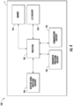
- the receiver 2, the set of detectors 52, 54, the reflector element 20, and/or the transmitters 3 may be communicably coupled to a controller 100.
- the receiver 2 may comprise controller 100.
- the controller 100 may comprise a memory 101, a processor 102, input/output circuitry 103, communication circuitry 105, transmitter processing circuitry 104, and detector signal processing circuitry 106.
- the controller 100 may be configured to execute one or more of the various operations described herein.
- the components are described with respect to functional limitations, it should be understood that the particular implementations necessarily include the use of particular hardware. It should also be understood that certain of the components described herein may include similar or common hardware.
- circuitry may both leverage use of the same processor, network interface, storage medium, or the like to perform their associated functions, such that duplicate hardware is not required for each set of circuitry.
- circuitry as used herein with respect to components of the controller 100 should therefore be understood to include particular hardware configured to perform the functions associated with the particular circuitry as described herein.
- circuitry should be understood broadly to include hardware and, in some embodiments, software for configuring the hardware.
- circuitry may include processing circuitry, storage media, network interfaces, input/output devices, and the like.
- other elements of the controller 100 may provide or supplement the functionality of particular circuitry.
- the processor 102 may provide processing functionality
- the memory 101 may provide storage functionality
- the communications circuitry 105 may provide network interface functionality, and the like.
- the processor 102 (and/or co-processor or any other processing circuitry assisting or otherwise associated with the processor) may be in communication with the memory 101 via a bus for passing information among components of the apparatus.
- the memory 101 may be non-transitory and may include, for example, one or more volatile and/or non-volatile memories.
- the memory 101 may be an electronic storage device (e.g., a computer readable storage medium).
- the memory 101 may be configured to store information, data, content, applications, instructions, or the like, for enabling the apparatus to carry out various functions in accordance with example embodiments of the present disclosure.
- the memory 101 may be configured to store partially or wholly any electronic information, data, data structures, embodiments, examples, figures, processes, operations, techniques, algorithms, instructions, systems, apparatuses, methods, look-up tables, or computer program products described herein, or any combination thereof.
- the memory 101 may be configured to store transmitter signal data, gas detection data, system historical data, an/or the like.
- the processor 102 may be embodied in a number of different ways and may, for example, include one or more processing devices configured to perform independently. Additionally or alternatively, the processor may include one or more processors configured in tandem via a bus to enable independent execution of instructions, pipelining, and/or multithreading.
- processing circuitry may be understood to include a single core processor, a multi-core processor, multiple processors internal to the apparatus, and/or remote or "cloud" processors.
- the processor 102 may be configured to execute instructions stored in the memory 101 or otherwise accessible to the processor. Alternatively, or additionally, the processor may be configured to execute hard-coded functionality. As such, whether configured by hardware or software methods, or by a combination thereof, the processor may represent an entity (e.g., physically embodied in circuitry) capable of performing operations according to an embodiment of the present disclosure while configured accordingly. Alternatively, as another example, when the processor is embodied as an executor of software instructions, the instructions may specifically configure the processor to perform the algorithms and/or operations described herein when the instructions are executed. For example, in various embodiments, the processor 102 may comprise drive circuitry configured to generate a signal.
- the drive circuitry may be configured to generate a signal defined at least in part by one or more predetermined signal characteristics, such as, for example, a signal frequency, to be received by a transmitter 3, wherein the signal may cause the transmitter 3 to emit a radiation beam signal towards a reflector face 24 of the receiver 2, as described herein.
- a signal defined at least in part by one or more predetermined signal characteristics, such as, for example, a signal frequency
- the controller 100 may include input-output circuitry 103 that may, in turn, be in communication with the processor 102 to provide output to the user and, in some embodiments, to receive input such as a command provided by the user.
- the input-output circuitry 103 may comprise a user interface, such as a graphical user interface (GUI), and may include a display that may include a web user interface, a GUI application, a mobile application, a client device, or any other suitable hardware or software.
- GUI graphical user interface
- the input-output circuitry 103 may also include a display device, a display screen, user input elements, such as a touch screen, touch areas, soft keys, a keyboard, a mouse, a microphone, a speaker (e.g., a buzzer), a light emitting device (e.g., a red light emitting diode (LED), a green LED, a blue LED, a white LED, an infrared (IR) LED, an ultraviolet (UV) LED, or a combination thereof), or other input-output mechanisms.
- a display device e.g., a display screen, user input elements, such as a touch screen, touch areas, soft keys, a keyboard, a mouse, a microphone, a speaker (e.g., a buzzer), a light emitting device (e.g., a red light emitting diode (LED), a green LED, a blue LED, a white LED, an infrared (IR) LED, an ultraviolet (UV) LED, or a
- the processor 102, input-output circuitry 103 (which may utilize the processing circuitry), or both may be configured to control one or more functions of one or more user interface elements through computer-executable program code instructions (e.g., software, firmware) stored in a non-transitory computer-readable storage medium (e.g., memory 101).
- Input-output circuitry 103 is optional and, in some embodiments, the controller 100 may not include input-output circuitry.
- the controller 100 may generate user interface data for display by one or more other devices with which one or more users directly interact and transmit the generated user interface data to one or more of those devices.
- the controller 100, using user interface circuitry may generate user interface data for display by one or more display devices and transmit the generated user interface data to those display devices.
- the communications circuitry 105 may be a device or circuitry embodied in either hardware or a combination of hardware and software that is configured to receive and/or transmit data from/to a network and/or any other device, circuitry, or module in communication with the system 1.
- the communications circuitry 105 may be configured to communicate with one or more computing devices via wired (e.g., USB) or wireless (e.g., Bluetooth, Wi-Fi, cellular, and/or the like) communication protocols.
- the processor 102 may be configured to communicate with the transmitter processing circuitry 104.
- the transmitter processing circuitry 104 may be a device or circuitry embodied in either hardware or a combination of hardware and software that is configured to receive, process, generate, and/or transmit data, such as transmitter signal data generated by one or more detectors.
- the transmitter processing circuitry 104 may be configured to receive and/or retrieve transmitter signal data from one or more transmitters.
- the transmitter signal data received by the transmitter processing circuitry 104 may comprise, for example, one or more signal data for one or more emitted radiation beam signal produced/generated by a transmitter.
- the transmitter processing circuitry 104 may be configured to control the acquisition of beam signals from one or more transmitters.
- the transmitter processing circuitry 104 may be communicably coupled to the transmitters and configured to provide a signal (e.g., drive signal) to the transmitters to cause emission of radiation beam signals by the transmitters.
- the transmitter processing circuitry 104 may be configured to control the sequence of emission of radiation beams from one or more transmitters.
- the transmitter processing circuitry 104 may be configured to control one or more transmitters to emit radiation beams sequentially based at least in part on a time-delay scheme/protocol and/or other suitable schemes/protocols for enabling sequential emission of one or more transmitters.
- the transmitter processing circuitry 104 may be configured to cause a first transmitter to emit a first radiation beam at time t1 and cause a second transmitter 3 to emit a second radiation beam at time t2 after a delay. Further, continuing with the example, the transmitter processing circuitry 104 may be configured to cause a third transmitter to emit a third radiation beam at a time t3 after another delay and may continue this process until all transmitters have been caused to emit radiation beam. Furthermore, the transmitter processing circuitry 104 may again repeat the above process. As another non-limiting example, the transmitter processing circuitry 104 may be configured to cause the transmitters (e.g., radiation sources thereof) to emit radiation beam at predetermined intervals.
- the transmitters e.g., radiation sources thereof
- the processor 102 may be configured to communicate with the detector signal processing circuitry 106.
- the detector signal processing circuitry 106 may be a device or circuitry embodied in either hardware or a combination of hardware and software that is configured to receive, process, generate, and/or transmit data, such as detector signal data (e.g., output signal data) generated by one or more detectors.
- the detector signal processing circuitry 106 may be configured to receive and/or retrieve detector signal data from a set of detectors.
- the detector signal data (e.g., detection signal) received by the detector signal processing circuitry 106 may comprise, for example, one or more signal data (e.g., intensity/signal strength) for one or more emitted radiation beam signals produced/generated by a transmitter.
- signal data e.g., intensity/signal strength
- detector signal processing circuitry 106 may be configured to distinguish signal data (e.g., intensity) for a first radiation beam produced by a first transmitter from signal data produced for a second radiation beam by a second transmitter, based at least in part on a signal analysis process and/or processes. Further, in various embodiments, the detector signal processing circuitry 106 may be configured to execute one or more signal analysis processes and/or processes to detect and/or calculate attenuation in signal intensity based at least in part on output data (e.g., intensity data/signal) received from one or more detectors, to generate a detection signal that may be indicative of the presence of gas in an area.
- output data e.g., intensity data/signal
- the controller 100 may be configured to analyze and/or process the output signals from a set of detectors based at least in part on comparing the output signals (e.g., the intensity measured by a first detector at a sample wavelength to the intensity measured by a second detector at a reference wavelength).
- detector signal processing circuitry 106 may be configured to execute one or more signal analysis processes and/or data transformation operations so as to process at least a portion of the detector signal data into formatted data that may be communicated to one or more external devices.
- the detector signal processing circuitry 106 may be configured to execute one or more of the operations described herein at two or more instances, so as to facilitate the receiving, processing, generating, and/or transmitting of signal data at various instances (e.g., runtimes) over time.
- the detector signal processing circuitry 106 may be configured to store at least a portion of the resultant data corresponding to one or more of the operations described herein as historical system data that, for example, may be associated with one or more instances (e.g., an installation instance, a particular runtime).
- the detector signal processing circuitry 106 may be configured to access at least a portion of the historical system data (e.g., via the memory 101) in order to facilitate the execution of one or more operations described herein.
- the multi-directional open path detector system 1 may be connected to a power supply (not shown) configured to receive power and power the various components of the multi-directional open path detector system 1.
- the power supply may comprise one or more batteries, one or more capacitors, one or more constant power supplies (e.g., a wall outlet) and/or the like.
- the configuration of the receiver 2 may be varied to achieve different field of views (e.g., customized field of views).
- the configuration and/or orientation of the receiver 2 may be based at least in part on the direction and/or angle of the beam path between the transmitters 3 and the reflector faces 24 of the reflector element 20.
- the direction and/or angle of the beam path between the transmitters 3 and the reflector faces 24 of the reflector element 20 may be selected based at least in part on the configuration of the receiver 2. (e.g., the configuration of the reflector element 20 and/or the optical element 30)
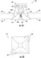
- FIG 5A schematically illustrates another exemplary receiver 200 of a multi-directional open path detector system 1 according to various embodiments of the present invention.
- the receiver 200 may comprise a reflector element 210, an optical element 300, and a set of detectors 520, 540 configured to receive incoming radiation beam signals 360 (e.g., at least a portion of each incoming radiation beam signal) from each of the transmitters 3 (as described above).
- incoming radiation beam signals 360 e.g., at least a portion of each incoming radiation beam signal
- reflector element 210 may comprise a plurality of reflector faces 240 (e.g., one or more mirrors) configured to reflect incoming beam signals (incoming beam) towards the optical element 300 of the receiver 200.
- Figure 5B schematically illustrates a top view of an exemplary reflector element 210.
- the reflector faces 240 may comprise at least a portion thereof having a curved reflecting surface (e.g., curved mirror face), such that collimated incoming beam signal 360 incident on the reflector faces 240 may be reflected towards the optical element 300 at an angle (e.g., greater than 90 degrees) relative to the incident radiation beam.
- the optical element 300 may comprise a flat mirror.
- the optical element 300 may comprise a substantially flat mirror face 320 orientated such that the incoming radiation beams reflected from each reflector face 240 incidents on the mirror face of optical element 300.
- the mirror face 320 may have a length L, such that each reflected incoming radiation beam incident on a reflector face 240 is reflected towards the mirror face 320.
- the optical element 300 may be configured to redirect (e.g., converge/concentrate) the reflected incoming radiation beam 360 towards at least one detector (e.g., detector 520 and/or detector 540) via a beam splitter 600 (similar to beam splitter 60).
- the beam splitter 600 may be configured to split a redirected radiation beam into a first radiation beam portion 360A and a second radiation beam portion 360B as described above with reference to Figure 2 , and may be configured to direct the first and second radiation beam portions 360A, 360B to the detectors 520 and 540 (as described above with reference to Figure 2 ).
- the various components (as described herein) of the optical element 300 and/or the reflector element 210 may comprise a variety of shapes.
- the reflector faces of the reflector element may comprise a flat shape (e.g., substantially flat), while the optical element comprise a curved shape.
- both the reflector faces of the reflector element and the optical element may comprise a curved shape.
- the reflector faces of the reflector element may comprise a curved shape, while the optical element comprises a flat shape (e.g., substantially flat shape).
- FIG. 6 illustrates an exemplary operation of a multi-directional open path detector system 1 according to various embodiments of the present invention.
- a receiver and a plurality of transmitters may be arranged in a monitored area, such as a gas pipeline environment.
- the exemplary multi-directional open path detector system 1 may be utilized to detect a gas leakage 80 from a pipeline 70.
- the gas can include any number of gases (e.g., methane, ammonia, hydrocarbons, and/or other gases).
- a controller communicably coupled to the receiver 2 and/or the plurality of transmitters 3 may transmit drive signals to the transmitters 3 sequentially to cause emission of radiation beam signals by the transmitters.
- the controller may form a portion of the receiver 2.
- Each emitted radiation beam may travel through a beam path to a reflector face 24 of the reflector element 20 of the receiver 2, wherein each transmitter emits radiation signal (e.g., collimated radiation beam) in a beam path direction that is different from other transmitters of the plurality of transmitters.
- the incoming radiation beam incident on a reflector face 24 may be reflected by the reflector face 24 towards an optical element 30.
- the optical element 30 may redirect (e.g., converge/concentrate/focus) the reflected incoming radiation beam via a beam splitter 60 (as described with reference to Figure 2 ) to a first detector and a second detector, wherein the first detector 52 (as described with reference to Figure 2 ) may receive a first radiation beam portion at a first wavelength (sample wavelength) and the second detector 54 (as described with reference to Figure 2 ) may receive a second radiation beam portion at a second wavelength (reference wavelength).
- the first detector may generate a first output signal (e.g., signal intensity at sample wavelength) based at least in part on measuring the intensity of the first radiation beam portion
- the second detector may generate a second output signal (e.g., signal intensity at the reference wavelength) based at least in part on measuring the intensity of the second radiation beam portion.
- a controller e.g., controller 100 coupled to (or forming a portion thereof) the receiver 2 may receive each output signal (e.g., first and second output signals) and process and/or analyze the output signals to generate a detection signal, based at least in part on the output signals (e.g., ratio measure and/or difference measure as described above), that may be indicative of the presence of the leaked gas 80 (e.g., detected gas) in the area.
Landscapes
- Physics & Mathematics (AREA)
- General Physics & Mathematics (AREA)
- Engineering & Computer Science (AREA)
- Spectroscopy & Molecular Physics (AREA)
- General Health & Medical Sciences (AREA)
- Biochemistry (AREA)
- Analytical Chemistry (AREA)
- Chemical & Material Sciences (AREA)
- Immunology (AREA)
- Pathology (AREA)
- Life Sciences & Earth Sciences (AREA)
- Health & Medical Sciences (AREA)
- Mechanical Engineering (AREA)
- General Engineering & Computer Science (AREA)
- Investigating Or Analysing Materials By Optical Means (AREA)
Applications Claiming Priority (1)
| Application Number | Priority Date | Filing Date | Title |
|---|---|---|---|
| IN202211051141 | 2022-09-07 |
Publications (1)
| Publication Number | Publication Date |
|---|---|
| EP4336162A1 true EP4336162A1 (de) | 2024-03-13 |
Family
ID=87557831
Family Applications (1)
| Application Number | Title | Priority Date | Filing Date |
|---|---|---|---|
| EP23189732.3A Pending EP4336162A1 (de) | 2022-09-07 | 2023-08-04 | Multidirektionales detektorsystem mit offenem weg und verfahren zur verwendung davon |
Country Status (3)
| Country | Link |
|---|---|
| US (1) | US20240077377A1 (de) |
| EP (1) | EP4336162A1 (de) |
| CN (1) | CN117664453A (de) |
Families Citing this family (1)
| Publication number | Priority date | Publication date | Assignee | Title |
|---|---|---|---|---|
| CN119826117B (zh) * | 2025-01-24 | 2025-10-24 | 常州大学 | 基于地形与温度修正的燃气管道泄漏热辐射预测方法 |
Citations (2)
| Publication number | Priority date | Publication date | Assignee | Title |
|---|---|---|---|---|
| EP0018458A2 (de) * | 1978-12-07 | 1980-11-12 | The English Electric Company Limited | Optische Teilchenanalysevorrichtung |
| US20120140231A1 (en) * | 2009-05-01 | 2012-06-07 | Xtrails Technologies Ltd | particle detectors |
Family Cites Families (6)
| Publication number | Priority date | Publication date | Assignee | Title |
|---|---|---|---|---|
| NL8503360A (nl) * | 1985-12-05 | 1987-07-01 | Tno | Werkwijze voor het vaststellen van de verdeling van een gas in een ruimte, retro-reflecterend scherm voor infrarode straling en inrichting voor het met behulp van zo een scherm en een stralingsbron voor infrarode straling vaststellen van de verdeling van een gas in een ruimte. |
| DE10005923C2 (de) * | 2000-02-10 | 2002-06-27 | Draeger Safety Ag & Co Kgaa | Infrarotoptische Gasmessvorrichtung und Gasmessverfahren |
| DE102018112895B4 (de) * | 2018-05-30 | 2024-05-08 | Presens Precision Sensing Gmbh | System, Vorrichtung und Verfahren zur Erfassung mindestens einer Veränderlichen während eines biologisch / chemischen Prozesses |
| US11821814B2 (en) * | 2021-03-17 | 2023-11-21 | General Electric Company | Leak detection system and method |
| CN113853512B (zh) * | 2021-08-26 | 2024-10-18 | 江苏旭海光电科技有限公司 | 一种分段扫描傅里叶变换光谱仪 |
| JPWO2024019029A1 (de) * | 2022-07-20 | 2024-01-25 |
-
2023
- 2023-08-04 EP EP23189732.3A patent/EP4336162A1/de active Pending
- 2023-08-21 CN CN202311052102.3A patent/CN117664453A/zh active Pending
- 2023-08-23 US US18/454,524 patent/US20240077377A1/en active Pending
Patent Citations (2)
| Publication number | Priority date | Publication date | Assignee | Title |
|---|---|---|---|---|
| EP0018458A2 (de) * | 1978-12-07 | 1980-11-12 | The English Electric Company Limited | Optische Teilchenanalysevorrichtung |
| US20120140231A1 (en) * | 2009-05-01 | 2012-06-07 | Xtrails Technologies Ltd | particle detectors |
Also Published As
| Publication number | Publication date |
|---|---|
| CN117664453A (zh) | 2024-03-08 |
| US20240077377A1 (en) | 2024-03-07 |
Similar Documents
| Publication | Publication Date | Title |
|---|---|---|
| US10180393B2 (en) | Sample cell | |
| CN107850535B (zh) | 气体监测仪 | |
| JP6905992B2 (ja) | レーザ検出システム及び方法 | |
| EP3751255B1 (de) | Gasdetektion unter verwendung differentieller weglängenmessung | |
| US20160178736A1 (en) | Lidar system | |
| US20110233406A1 (en) | Multi-channel optical cell | |
| Shao et al. | RETRO: Retroreflector based visible light indoor localization for real-time tracking of IoT devices | |
| CN104220863B (zh) | 气体检测器系统 | |
| US20100188661A1 (en) | Multiple Beam Wide Band CRDS Cavity Sensor and Detector | |
| EP4336162A1 (de) | Multidirektionales detektorsystem mit offenem weg und verfahren zur verwendung davon | |
| CN109891213A (zh) | 带环反射器的气体检测器系统 | |
| JP2004536289A (ja) | レーザ光学的区域走査及び応答システムおよび方法 | |
| JP4358516B2 (ja) | ターゲットの特性決定のための訓練可能レーザ光センシングシステム | |
| US10732106B2 (en) | Two detector gas detection system | |
| CN106092963A (zh) | 多角度快速可调的激光甲烷浓度监测装置 | |
| US20240344974A1 (en) | Apparatus and method for sensing gas and particulate matter using an optical beam | |
| CN218382594U (zh) | 气体检测系统和移动装置 | |
| CN105318899B (zh) | 检测系统 | |
| EP4390345B1 (de) | Sensor mit einem omnidirektionalen sichtfeld | |
| US20140168652A1 (en) | Reflection measurement apparatus | |
| CN108507737A (zh) | 天然气站场泄漏监测装置 | |
| CN212410427U (zh) | 用于检测易燃易爆物的装置 | |
| KR102265045B1 (ko) | 광학식 가스센서 | |
| EP4461099A1 (de) | Beseitigung von spiegelsymmetrie und schwerkraftambiguität aus einem 2d-netz von vorrichtungen | |
| KR20150136815A (ko) | 가스 측정 센서 |
Legal Events
| Date | Code | Title | Description |
|---|---|---|---|
| PUAI | Public reference made under article 153(3) epc to a published international application that has entered the european phase |
Free format text: ORIGINAL CODE: 0009012 |
|
| STAA | Information on the status of an ep patent application or granted ep patent |
Free format text: STATUS: REQUEST FOR EXAMINATION WAS MADE |
|
| 17P | Request for examination filed |
Effective date: 20230804 |
|
| AK | Designated contracting states |
Kind code of ref document: A1 Designated state(s): AL AT BE BG CH CY CZ DE DK EE ES FI FR GB GR HR HU IE IS IT LI LT LU LV MC ME MK MT NL NO PL PT RO RS SE SI SK SM TR |