EP4336450A1 - Bereitstellung von poseinformationen für röntgenprojektionsbilder - Google Patents
Bereitstellung von poseinformationen für röntgenprojektionsbilder Download PDFInfo
- Publication number
- EP4336450A1 EP4336450A1 EP22194639.5A EP22194639A EP4336450A1 EP 4336450 A1 EP4336450 A1 EP 4336450A1 EP 22194639 A EP22194639 A EP 22194639A EP 4336450 A1 EP4336450 A1 EP 4336450A1
- Authority
- EP
- European Patent Office
- Prior art keywords
- pose
- ray projection
- projection image
- ray
- metric
- Prior art date
- Legal status (The legal status is an assumption and is not a legal conclusion. Google has not performed a legal analysis and makes no representation as to the accuracy of the status listed.)
- Withdrawn
Links
Images


Classifications
-
- G—PHYSICS
- G06—COMPUTING OR CALCULATING; COUNTING
- G06T—IMAGE DATA PROCESSING OR GENERATION, IN GENERAL
- G06T7/00—Image analysis
- G06T7/70—Determining position or orientation of objects or cameras
- G06T7/73—Determining position or orientation of objects or cameras using feature-based methods
-
- G—PHYSICS
- G06—COMPUTING OR CALCULATING; COUNTING
- G06T—IMAGE DATA PROCESSING OR GENERATION, IN GENERAL
- G06T7/00—Image analysis
- G06T7/10—Segmentation; Edge detection
-
- G—PHYSICS
- G06—COMPUTING OR CALCULATING; COUNTING
- G06T—IMAGE DATA PROCESSING OR GENERATION, IN GENERAL
- G06T2207/00—Indexing scheme for image analysis or image enhancement
- G06T2207/10—Image acquisition modality
- G06T2207/10116—X-ray image
-
- G—PHYSICS
- G06—COMPUTING OR CALCULATING; COUNTING
- G06T—IMAGE DATA PROCESSING OR GENERATION, IN GENERAL
- G06T2207/00—Indexing scheme for image analysis or image enhancement
- G06T2207/20—Special algorithmic details
- G06T2207/20084—Artificial neural networks [ANN]
-
- G—PHYSICS
- G06—COMPUTING OR CALCULATING; COUNTING
- G06T—IMAGE DATA PROCESSING OR GENERATION, IN GENERAL
- G06T2207/00—Indexing scheme for image analysis or image enhancement
- G06T2207/30—Subject of image; Context of image processing
- G06T2207/30004—Biomedical image processing
- G06T2207/30008—Bone
Definitions
- the present disclosure relates to providing pose information for X-ray projection images.
- a computer-implemented method, a computer program product, and a system, are disclosed.
- Projection X-ray imaging systems include an X-ray source and an X-ray detector.
- the X-ray source and the X-ray detector are separated by an examination region.
- An anatomical structure such as an ankle, a leg, or another part of a subject's body, may be disposed in the examination region in order to generate X-ray projection images of the anatomical structure.
- X-ray projection images are acquired by a projection X-ray imaging system that has a defined pose with respect to the anatomical structure.
- X-ray projection images are acquired using a single pose of the X-ray imaging system with respect to the anatomical structure, and so it is important that the pose that is used provides the desired information in the resulting X-ray projection images. For instance, the diagnosis of a fractured ankle bone may require the bone to be imaged using a pose in which the fracture is not obscured by other bones in the ankle. If an unsuitable pose is used, a repeat image may need to be acquired.
- anatomical structures with respect to projection X-ray imaging systems is conventionally performed manually, and in accordance with a protocol for the anatomical structure.
- a radiographer positions the anatomical structure by eye, and generates an initial image. If the initial image is unacceptable, the radiographer re-positions the anatomical structure based on their experience, and generates another image. This procedure may be repeated several times until an acceptable image is obtained, sometimes with only a marginal improvement in the resulting image. This approach therefore increases the amount of X-ray dose that is delivered to a subject, and also hampers workflow.
- a document US 2019/183438 A1 describes a method for ensuring correct positioning for a radiography recording.
- the method includes providing an examination request of the body region; pre-positioning the body region in the radiography system for the radiography recording; pre-positioning at least one of a recording unit of the radiography system and an image detector of the radiography system for the radiography recording; producing a positioning recording of the body region via the radiography system, the radiography system being switched into the fluoroscopy mode and the positioning recording being a fluoroscopy recording; producing positioning information from the positioning recording; and outputting the positioning information.
- a computer-implemented method of providing pose information for X-ray projection images comprises:
- a pose metric is generated for an X-ray projection image.
- the pose metric is generated based on a relative size of two or more projected sub-regions in the segmented X-ray projection image.
- the inventors have observed that this relative size serves as a reliable metric for the pose of the projection X-ray imaging system with respect to the anatomical structure.
- An operator may use the pose metric for various purposes, such as for example to determine the pose of the projection X-ray imaging system with respect to the anatomical structure, or to assess a suitability of the pose for acquiring the X-ray projection image, or to determine how to adjust the projection X-ray imaging system pose in order to acquire an improved X-ray projection image of the anatomical structure. Consequently, the method facilitates a reduction in the amount of X-ray dose that is delivered to a subject by reducing the number of X-ray image acquisitions that are repeated. The method also facilitates an improvement in workflow.
- the projection X-ray imaging system may be the DigitalDiagnost C90, or the Philips Azurion 7, or the MobileDiagnost M50 mobile digital X-ray system, all of which are marketed by Philips Healthcare, Best, the Netherlands.
- the projection X-ray imaging system may in general be provided by any type of projection X-ray imaging system.
- arrangements of X-ray imaging systems are described in which an X-ray source of the projection X-ray imaging system is mounted to a ceiling via a gantry, and a corresponding X-ray detector is mounted to a stand and held in the vertical position.
- This type of arrangement may be used by the DigitalDiagnost C90 imaging system mentioned above.
- this arrangement serves only as an example, and that the X-ray source and the X-ray detector of the projection X-ray imaging system may alternatively be arranged in a different manner.
- the X-ray source may be mounted to a stand, or to an articulating arm, and the X-ray detector may be mounted to the ceiling, or to an articulating arm and held in a different position.
- An arrangement may alternatively be used wherein the X-ray source and the X-ray detector are mounted to a common support structure.
- the support structure is a so-called C-arm.
- Other arrangements may alternatively be used in which the X-ray source and the X-ray detector are mounted to a common support structure that has a different shape to a C-arm, including arrangements wherein the support structure is provided by a so-called "O-arm".
- Other arrangements may alternatively be used wherein the X-ray source and the X-ray detector are mounted, or supported, in a different manner, including portable X-ray imaging systems such as the MobileDiagnost M50 mobile digital X-ray system mentioned above.
- the anatomical structure is an ankle.
- the ankle serves only as an example, and that in general the methods disclosed herein may be used to acquire X-ray projection images that represent any anatomical structure in the body of a subject.
- the methods may similarly be used to generate a pose metric for each of multiple images.
- the methods may for example be used to provide a pose metric for a temporal sequence of images and wherein the pose metric changes in response to changes in the pose of the projection X-ray imaging system during the sequence.
- the computer-implemented methods disclosed herein may be provided as a non-transitory computer-readable storage medium including computer-readable instructions stored thereon, which, when executed by at least one processor, cause the at least one processor to perform the method.
- the computer-implemented methods may be implemented in a computer program product.
- the computer program product can be provided by dedicated hardware, or hardware capable of running the software in association with appropriate software.
- the functions of the method features can be provided by a single dedicated processor, or by a single shared processor, or by a plurality of individual processors, some of which can be shared.
- processor or “controller” should not be interpreted as exclusively referring to hardware capable of running software, and can implicitly include, but is not limited to, digital signal processor "DSP” hardware, read only memory “ROM” for storing software, random access memory “RAM”, a non-volatile storage device, and the like.
- DSP digital signal processor
- ROM read only memory
- RAM random access memory
- examples of the present disclosure can take the form of a computer program product accessible from a computer-usable storage medium, or a computer-readable storage medium, the computer program product providing program code for use by or in connection with a computer or any instruction execution system.
- a computer-usable storage medium or a computer readable storage medium can be any apparatus that can comprise, store, communicate, propagate, or transport a program for use by or in connection with an instruction execution system, apparatus, or device.
- the medium can be an electronic, magnetic, optical, electromagnetic, infrared, or a semiconductor system or device or propagation medium.
- Examples of computer-readable media include semiconductor or solid state memories, magnetic tape, removable computer disks, random access memory "RAM”, read-only memory "ROM”, rigid magnetic disks and optical disks. Current examples of optical disks include compact disk-read only memory "CD-ROM”, compact disk-read/write "CD-R/W”, Blu-Ray TM and DVD.
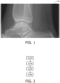
- Fig. 1 is an example of an X-ray projection image 120 representing an anatomical structure, in accordance with some aspects of the present disclosure.
- a radiographer may acquire an image such as the image illustrated in Fig. 1 during a clinical investigation for the presence of a fractured bone in the ankle, for example.
- a drawback of such projection X-ray images is the need for their acquisition using a projection X-ray imaging system that has a suitable pose with respect to the anatomical structure. This is a consequence of projection X-ray images being generated by projecting the attenuation arising from a three-dimensional object onto the surface of a two-dimensional X-ray detector. If the projection X-ray imaging system used to acquire the image illustrated in Fig. 1 were to have an unsuitable pose with respect the ankle, the fracture might be obscured by other bones in the ankle. This might result in the need to acquire another image, which increases the amount of X-ray dose that is delivered to a subject, and also hampers workflow.
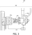
- Fig. 2 is a flowchart illustrating an example of a method of providing pose information for X-ray projection images, in accordance with some aspects of the present disclosure.
- Fig. 3 is a schematic diagram illustrating an example of a system 200 for providing pose information for X-ray projection images, in accordance with some aspects of the present disclosure.
- the system 200 includes one or more processors 210. Operations described in relation to the method illustrated in Fig. 2 , may also be performed by the one or more processors 210 of the system 200 illustrated in Fig. 3 . Likewise, operations described in relation to the one or more processors 210 of the system 200, may also be performed in the method described with reference to Fig. 2 .
- the computer-implemented method of providing pose information for X-ray projection images includes:
- a pose metric is generated for an X-ray projection image.
- the pose metric is generated based on a relative size of two or more projected sub-regions in the segmented X-ray projection image.
- the inventors have observed that this relative size serves as a reliable metric for the pose of the projection X-ray imaging system with respect to the anatomical structure.
- An operator may use the pose metric for various purposes, such as for example to determine the pose of the projection X-ray imaging system with respect to the anatomical structure, or to assess a suitability of the pose for acquiring the X-ray projection image, or to determine how to adjust the projection X-ray imaging system pose in order to acquire an improved X-ray projection image of the anatomical structure. Consequently, the method facilitates a reduction in the amount of X-ray dose that is delivered to a subject by reducing the number of X-ray image acquisitions that are repeated. The method also facilitates an improvement in workflow.
- X-ray projection data 110 is received.
- the X-ray projection data comprises an X-ray projection image 120 representing an anatomical structure 130.
- the X-ray projection data is acquired by a projection X-ray imaging system 140 that has a corresponding pose, P, with respect to the anatomical structure 130.
- a projection X-ray imaging system includes an X-ray source and an X-ray detector.
- the X-ray source and the X-ray detector are held in a static position with respect to an anatomical structure during the acquisition of the X-ray projection data.
- the projection X-ray imaging system may be said to have a pose with respect to the anatomical structure during the acquisition of the X-ray projection data.
- the X-ray projection data is acquired using a single pose of the projection X-ray imaging system with respect to the anatomical structure.
- the X-ray projection data may be used to generate an X-ray projection image, i.e. a two-dimensional image, representing the anatomical structure.
- the X-ray projection data that is acquired by a projection X-ray imaging system contrasts with the volumetric X-ray data that is generated by a computed tomography "CT" imaging system.
- CT imaging system an X-ray source and X-ray detector are rotated around an anatomical structure in order to acquire volumetric X-ray data from each of multiple poses of the CT imaging system with respect to an anatomical structure.
- the volumetric X-ray data is subsequently reconstructed into a three-dimensional, or volumetric, image of the anatomical structure.
- the X-ray projection data 110 that is received in the operation S110 may be received from various sources.
- the X-ray projection data 110 may be received from a projection X-ray imaging system, such as the projection X-ray imaging system 140 illustrated in Fig. 3 .
- the X-ray projection data 110 may be received by the one or more processors 210 of the system 200 illustrated in Fig. 3 .
- the X-ray projection data 110 may be received from another source, such as a computer readable storage medium, or the Internet or the Cloud, for example.
- the X-ray projection data 110 may have been acquired by a projection X-ray imaging system at an earlier point in time, and subsequently received in the operation S110 from the computer readable storage medium, or the Internet or the Cloud.
- the X-ray projection data 110 that is received in the operation S110 may be received via any form of data communication, including wired, optical, and wireless communication.
- wired or optical communication the communication may take place via signals transmitted on an electrical or optical cable, and when wireless communication is used, the communication may take place via RF or optical signals.
- the X-ray projection data 110 is acquired by a projection X-ray imaging system 140 that has a corresponding pose, P, with respect to the anatomical structure 130.
- Fig. 4 is a schematic diagram illustrating an example of a projection X-ray imaging system 140 having a pose, P, with respect to an anatomical structure 130, in accordance with some aspects of the present disclosure.
- the projection X-ray imaging system 140 illustrated in Fig. 4 corresponds to the projection X-ray imaging system 140 illustrated in Fig. 3 , and includes an X-ray source 140s, and an X-ray detector 140 D .
- An example of an anatomical structure is also illustrated in Fig. 3 and Fig. 4 in the form of an ankle. In both Fig. 3 and Fig.
- X-ray projection data for the ankle is acquired by detecting with the X-ray detector 140 D , X-ray radiation that is emitted by the X-ray source 140 S and which has passed through the ankle.
- the X-ray projection data represents a line integral of the ankle's X-ray attenuation along paths between the X-ray source 140s and the X-ray detector 140 D .
- the pose, P, of the X-ray imaging system 140 with respect to the ankle is illustrated via the orientation of the thick dark arrow in Fig. 4 with respect to the ankle.
- the pose, P is defined by the orientation of a central ray of the projection X-ray imaging system 140 with respect to the anatomical structure.
- the diagram within the dashed-outline box at the top right-hand side of Fig. 4 illustrates a generalized pose, P, of the projection X-ray imaging system 140 with respect to the anatomical structure 130.
- the pose, P is defined by the angles a and b with respect to a coordinate system of the anatomical structure 130.
- the angle a may be defined as a rotational angle of the central ray of the projection X-ray imaging system 140 around a longitudinal axis of the subject
- the angle b may be defined as a tilt angle of the central ray of the projection X-ray imaging system 140 with respect to a cranial-caudal axis of the subject.
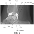
- Fig. 5 is an example of a segmented X-ray projection image 120 and includes examples of projected sub-regions 150 1..m of an anatomical structure, in accordance with some aspects of the present disclosure.
- the segmentation has resulted in a delineation of the projected sub-regions 150 1..m of the ankle.
- a first projected region of the Tibia 150 1 a second projected region of the Tibia 150 2 , a projected joint gap 150 3 between the Tibia and the Talus, a first articulating surface of the Talus 150 4 , an overlap between the Fibula and the Talus 150 5 , and a second articulating surface of the Talus 150 6 .
- the projected sub-regions 150 1..m of the anatomical structure 130 that are identified by the segmentation operation 120 represent one or more of: a portion of a bone 150 1..2 , 150 4..6 and a space between two bones 150 3 .
- a portion of a bone may include a portion of the diaphysis of the bone, i.e. the shaft, or a portion of the metaphysis, or a portion of the epiphysis.
- portions of a bone that may be identified as projected sub-regions in the operation S 120 include projections of the perimeters of the bones, and also projections of facets of the bone, such as a projection of an articulating surface of the bone. In the example illustrated in Fig.
- the projected sub-regions 150 1..m represent portions of the Tibia, i.e. 150 1..2 , portions of the Fibula, i.e. 150 5 , and portions of the Talus, i.e. 150 4 and 150 6 .
- Items 150 4 and 150 6 in Fig. 5 are examples of projections of articulating surfaces of a bone, i.e. the first articulating surface of the Talus 150 4 and second articulating surface of the Talus 150 6 .
- Item 150 3 in Fig. 5 is an example of a projection of a space between two bones, i.e. the projected joint gap 150 3 between the Tibia and the Talus.
- the projected sub-regions 150 1..m may be defined in various ways. In one example, at least one of the two or more projected sub-regions is defined at least in part by a perimeter of a portion of at least one of the bones in the X-ray projection image 150 1..6 .
- the projected sub-region 150 1 is defined at least at its upper, left-hand, and lower extremities by a perimeter of a facet of a bone, more specifically an articulating surface of the Tibia.
- the projected sub-region 150 2 is defined at least at its upper, right-hand, and lower extremities by a perimeter of a facet of a bone, more specifically an articulating surface of the Tibia.
- At least one of the two or more projected sub-regions is defined at least in part by an intersection between a plurality of bones in the X-ray projection image.
- the projected sub-region 150 1 is defined at least at its right-hand extremity by an intersection between the Fibula and the Tibia.
- the projected sub-region 150 2 is defined at least at its left-hand extremity by an intersection between the Fibula and the Tibia.
- at least one of the two or more projected sub-regions is defined at least in part by an intersection between a space between two bones 150 3 and a further bone in the X-ray projection image 120. Whilst this is not illustrated explicitly in Fig. 5 , a projected sub-region in accordance with this example might be defined by an intersection between the joint gap 150 3 and the Fibula.
- a projected sub-region may also be defined by a combination of these examples.
- the operation S120 in which the X-ray projection image 120 is segmented in order to identify the plurality of projected sub-regions 150 1..m of the anatomical structure 130 may be performed using various techniques.
- One example technique involves applying a segmentation algorithm to the received X-ray projection data 110. Segmentation algorithms such as model-based segmentation, watershed-based segmentation, region growing, level sets or graph cuts, may be used for this purpose.
- Another example technique involves inputting the received X-ray projection data 110 into a neural network that is trained to segment X-ray projection images representing the anatomical structure 130.
- An example of such a neural network is the first neural network NN1 that is described later with reference to Fig. 8 .
- a pose metric for the X-ray projection image 120 is generated based on a relative size of two or more of the projected sub-regions 150 1..m in the segmented X-ray projection image 120.
- this relative size serves as a reliable metric for the pose of the projection X-ray imaging system with respect to the anatomical structure.
- Fig. 6 illustrates three examples of segmented X-ray projection images 120 1..3 that include examples of projected sub-regions 150 1..m of an anatomical structure, and which have been acquired from different poses P 1 ( Fig. 6a ), P 2 ( Fig. 6b ) and P 3 ( Fig. 6c ) of a projection X-ray imaging system with respect to the anatomical structure, in accordance with some aspects of the present disclosure.
- the diagrams within the dashed-outline boxes illustrate by way of a thick dark arrow, the pose P 1..3 of a projection X-ray imaging system with respect to an anatomical structure 130.
- the pose P 1..3 is used to acquire the corresponding X-ray projection images 120 1..3 that are illustrated in the lower portion of Fig. 6 .
- the pose P 1..3 of the projection X-ray imaging system 140 is defined in the manner described above with reference to Fig. 4 .
- the pose P 1..3 is defined by the orientation of a central ray of the projection X-ray imaging system with respect to the anatomical structure.
- the pose, P 1..3 may be defined by the angles a and b with respect to a coordinate system of the anatomical structure 130.
- the angle a may be defined as a rotational angle of the central ray of the projection X-ray imaging system around a longitudinal axis of the subject
- the angle b may be defined as a tilt angle of the central ray of the projection X-ray imaging system with respect to a cranial-caudal axis of the subject.
- the pose P 2 is optimal for generating an X-ray projection image representing the ankle.
- the Fibula tip is aligned centrally with respect to the Tibia, and the projected joint gap 150 3 between the Tibia and the Talus is visible continuously along the length of the articulating surface of the Tibia.
- the following projected sub-regions are visible in Fig. 6b with the optimal pose P 2 : a first projected region of the Tibia 150 1 , a second projected region of the Tibia 150 2 , a projected joint gap 150 3 between the Tibia and the Talus, and an overlap between the Fibula and the Talus 150 5 .
- a size may be calculated for each of these projected sub-regions.
- the size may be an area, or a distance measurement, for each projected sub-region.
- the area may be calculated as the total area of the projected sub-region, or as the area of a shape that is fitted to the projected sub-region, and the distance measurement may be calculated as a maximum, or a minimum, or a mean distance for the projected sub region, or a distance measurement of a shape that is fitted to the projected sub-region.
- the size may be calculated in terms of units such as (square) millimeters, (square) centimeters, and so forth, or it may be calculated in terms of another reference unit such as image pixels.
- the pose P 1 is obtained from the pose P 2 by rotating the projection X-ray imaging system anticlockwise around the y-axis of the anatomical structure by approximately 5 degrees.
- the pose P 1 is sub-optimal for generating an X-ray projection image representing the ankle. This is in-part because the joint projected joint gap 150 3 between the Tibia and the Talus is no longer continuous along the length of the articulating surface of the Tibia.
- the size of the first projected region of the Tibia 150 1 has increased, and the size of the second projected region of the Tibia 150 2 has decreased.
- the size of the overlap between the Fibula and the Talus 150 5 has also decreased.
- the pose P 3 is obtained from the pose P 2 by rotating the projection X-ray imaging system clockwise around the y-axis of the anatomical structure by approximately 5 degrees.
- the pose P 3 is sub-optimal for generating an X-ray projection image representing the ankle. This is in-part because the joint projected joint gap 150 3 between the Tibia and the Talus is no longer continuous along the length of the articulating surface of the Tibia.
- the size of the first projected region of the Tibia 150 1 has decreased, and the size of the second projected region of the Tibia 150 2 has increased.
- the size of the overlap between the Fibula and the Talus 150 5 has also decreased.
- a consequence of the changes in the size of the projected sub-regions 150 1..m with rotation around the y-axis is that the relative size of two or more of the projected sub-regions 150 1..m in the segmented X-ray projection image 120, may be used to determine the pose, P 1..3 of the projection X-ray imaging system with respect to the anatomical structure 130.
- the relative size of the projected sub-region 150 1 in comparison to the size of the projected sub-region 150 2 provides a measure of the rotation of the ankle around the y-axis of the anatomical structure.
- the relative size of the projected sub-region 150 4 in comparison to the size of the projected sub-region 150 3 also provides a measure of the rotation of the ankle around the y-axis of the anatomical structure.
- Other poses of the projection X-ray imaging system with respect to the anatomical structure 130 may be determined from the relative sizes of the projected sub-regions 150 1..m in a similar manner.
- the pose metric represents the pose, P, of the projection X-ray imaging system 140 with respect to the anatomical structure 130. In some examples, the pose metric represents a suitability of the projection X-ray imaging system pose, P, for acquiring the X-ray projection image 120. In some examples, the pose metric represents feedback for adjusting the projection X-ray imaging system pose, P, in order to acquire a subsequent X-ray projection image representing the anatomical structure 130. The pose metric may also represent a combination of these examples.
- the pose metric is outputted to provide the pose information for the X-ray projection image 120.
- the pose metric may be outputted in various ways, including graphically, and audially.
- the pose metric may be outputted graphically to a display of a monitor, a tablet, or another device.
- the pose of the projection X-ray imaging system 140 may be outputted graphically as an icon similar to that illustrated in the upper portion of Fig. 6 .
- Feedback for adjusting the projection X-ray imaging system pose may be outputted in a similar manner by displaying an arrow indicating how the pose should be adjusted in order to obtain an improved image of the anatomical structure.
- Feedback for adjusting the projection X-ray imaging system pose may alternatively be outputted audially via a loudspeaker, headphones, and so forth.
- an audio message may be outputted such as "rotate X-ray source by ten degrees to the left", or “rotate ankle by 5 degrees to the left", and so forth.
- a suitability of the projection X-ray imaging system pose, P, for acquiring the X-ray projection image 120 may be outputted by outputting a color, or another visual indication indicating whether or not the pose is suitable.
- the X-ray projection image 120 may be provided with a red outline indicating that the pose is unsuitable, and a green outline indicating that the pose is indeed suitable.
- the pose metric represents feedback for adjusting the projection X-ray imaging system pose, P, in order to acquire a subsequent X-ray projection image representing the anatomical structure 130, and the pose metric is used to automatically adjust the projection X-ray imaging system pose, P.
- the feedback is outputted to a control system that generates control signals for controlling one or more motors or actuators to adjust the pose of the projection X-ray imaging system that generated the X-ray projection image 120.
- the projection X-ray imaging system may include various sensors such as rotational encoders and position sensors that measure the pose of the projection X-ray imaging system, and which operate in combination with the one or more motors or actuators to provide the adjusted pose.
- the feedback may also be outputted to a user as a recommended pose, whereupon the pose is adjusted automatically in response to the user's acceptance of the recommended pose.
- This example has the benefit of obviating the need to manually re-position the projection X-ray imaging system and/or the patient in order to acquire the subsequent X-ray projection image, thereby saving time and improving workflow.
- the pose metric may be outputted and stored with the X-ray projection image 120.
- the X-ray projection image 120 may be stored in a standardized format, such as the DICOM format.
- the pose metric may be stored together with the X-ray projection image 120 in a so-called "secondary capture” DICOM format or in a "presentation state” DICOM format.
- the pose metric and the X-ray projection image 120, in the secondary capture DICOM format or in the presentation state DICOM format may then be transmitted to a PACS viewing station for viewing by a radiologist.
- the pose metric and the X-ray projection image 120 may be displayed on the PACS viewing station as a secondary capture image, or as a presentation state image, or as a structured report, for example.
- the relative size of two or more of the projected sub-regions 150 1..m is used to generate a pose metric for the X-ray projection image.
- the sizes of projected sub-regions are calculated from the X-ray projection image.
- the sizes of projected sub-regions are calculated using an image processing technique.
- the relative sizes of the projected sub-regions 150 1 , and 150 2 described above with reference to Fig. 6 may be measured and used as a measure of rotation of the projection X-ray imaging system around the y-axis of the anatomical structure 130, and thus a measure of the pose of the projection X-ray imaging system with respect to the anatomical structure. As the rotation of the projection X-ray imaging system is rotated clockwise around the y-axis throughout the sequence of Fig. 6a - Fig.
- the ratio of the size of the projected sub-region 150 1 to the size of the projected sub-region 150 2 decreases.
- the relative sizes of other projected sub-regions may be used to augment, and therefore improve the accuracy, of the pose that is determined from the projected sub-regions 150 1 , and 150 2 .
- the ratio of the size of the projected sub-region 150 5 to the projected joint gap 150 3 between the Tibia and the Talus also changes throughout the sequence of Fig. 6a - Fig. 6c , and also with rotation around the x-axis, and so this may also improve the accuracy, of the pose that is determined from the projected sub-regions 150 1 , and 150 2 .
- the pose metric represents the pose, P, of the projection X-ray imaging system 140 with respect to the anatomical structure 130.
- This example may be implemented by measuring, at multiple poses, the sizes of multiple projected sub-region 150 1..m for a reference anatomical structure such as that illustrated in Fig. 6 , and generating a functional relationship between the relative sizes and the corresponding poses.
- the functional relationship could be provided by a graph, or a lookup table, for example.
- the graph, or lookup table may then be interrogated in order to determine the pose for a new projection X-ray image representing the anatomical structure.
- the pose metric represents a suitability of the projection X-ray imaging system pose, P, for acquiring the X-ray projection image 120.
- This example may be implemented in a similar manner by determining the pose, P, as described above, and by checking the pose against a range of poses that have been labelled in the functional relationship as being suitable for acquiring the X-ray projection image.
- the pose metric represents a suitability of the projection X-ray imaging system pose, P, for acquiring the X-ray projection image 120
- the operation of generating S130 a pose metric for the X-ray projection image 120 comprises comparing the relative size of the two or more projected sub-regions 150 1..m with at least one threshold value.
- the threshold value may define a range of poses that are suitable for acquiring the X-ray projection image 120.
- a radiologist may set the threshold value so as to define images that are clinically acceptable for imaging the anatomical structure.
- the pose metric represents feedback for adjusting the projection X-ray imaging system pose, P, in order to acquire a subsequent X-ray projection image representing the anatomical structure 130.
- This example may be implemented by calculating the pose for a new projection X-ray image as described above, and also calculating a pose adjustment as the difference between the calculated pose and a reference pose for acquiring an X-ray projection image representing the anatomical structure 130.
- the calculation may result in a pose adjustment that is calculated as the difference between the pose values P 1 and P 2 , or as the difference between the pose values P 3 and P 2 ; P 2 being the optimal pose for the anatomical structure.
- the pose metric for the X-ray projection image 120 is determined based further on anatomical landmarks in the X-ray projection image. This provides redundancy to the determination of a pose metric based on a relative size of two or more of the projected sub-regions 150 1..m in the segmented X-ray projection image 120.
- This example is beneficial in improving the accuracy of the pose metric in situations in which the X-ray projection image does not permit an accurate segmentation in the operation S130.
- bone contours may be poorly visible with some poses, and with some X-ray imaging settings.
- anatomical variability, and implants in the anatomy may result in the obstruction of image features in the X-ray projection image, confounding the segmentation operation.
- the method described with reference to Fig. 1 includes:
- Fig. 7 is an example of a segmented X-ray projection image 120 and includes examples of projected sub-regions 150 1..m of an anatomical structure, and examples of the positions of a plurality of anatomical landmarks 160 1..n , in accordance with some aspects of the present disclosure.
- the segmented X-ray projection image 120 illustrated in Fig. 7 represents a magnified portion of Fig. 5 around the Fibula tip 160 1 , and includes the positions of the following anatomical landmarks: Fibula tip 160 1 , and the tip of the tibial malleolus 160 2 .
- the pose metric for the X-ray projection image 120 may be generated based on the position of one or more anatomical landmarks 160 1..n in the X-ray projection image 120, as well as a relative size of two or more of the projected sub-regions 150 1..m in the segmented X-ray projection image 120.
- the positions of these landmarks may also be determined with respect to the position of one or more projected sub-regions 150 1..m .
- further information may also be derived from the X-ray projection image 120 and used to generate the pose metric. For instance, in one example, distances between the positions of the plurality of anatomical landmarks 160 1..n may be measured. With reference to Fig. 7 , in this example, a plurality of distances 170 1..i have been calculated between different anatomical landmarks. For instance, the distances 170 1..3 represent radii of circular approximations of the two Talus and the lower Tibia condyles. The distance 170 4 represents the distance between the Fibula tip and the tip of the tibial malleolus.
- the distance 170 5 represents the posterior joint gap represented by the distance between the circular approximations of the Tibia condyle and the closer Talus condyle.
- the distance 170 6 represents the central joint gap represented by the distance between the circular approximations of the Tibia condyle and the closer Talus condyle.
- the distance 170 8 represents the anterior joint gap represented by the distance between the circular approximations of the Tibia condyle and the closer Talus condyle.
- the distance 170 7 represents the anterior distance between Fibula and Tibia at defined significant positions. As may be appreciated, these distances vary in accordance with the pose of the X-ray imaging system that is used to generate the X-ray projection image 120 illustrated in Fig.
- angles between trajectories that are defined by the plurality of anatomical landmarks may be measured, and these may be used in a similar manner to characterize the pose of the X-ray imaging system that is used to generate the X-ray projection image 120 illustrated in Fig. 7 .
- these anatomic segments are transformed by a mapping ⁇ F u , v ⁇ R M , where M is the dimension of the feedback to correct the pose of the projection X-ray imaging system with respect to the anatomical structure.
- the mapping ⁇ is a linear or non-linear mapping from anatomic structures and additional geometrical measures to pose feedback.
- the positions of the anatomical landmarks 160 1..n in the X-ray projection image 120 are mapped to corresponding landmarks in a reference image, and the pose metric for the X-ray projection image is determined based on the mapped positions of the plurality of anatomical landmarks 160 1..n with respect to the corresponding landmarks in the reference image.
- the reference image is obtained by projecting a 3D model representing the anatomical structure using different poses of a projection X-ray imaging system with respect to the anatomical structure.
- the 3D model is projected in a virtual sense using a model of a projection X-ray imaging system in which the X-ray source and X-ray detector are arranged in the same manner as in the imaging system that was used to generate the X-ray projection image.
- the projected landmarks in the reference image appear in positions that are characteristic of the pose of the model of the projection X-ray imaging system that is used to generate the reference image. Consequently, by matching the positions of the anatomical landmarks 160 1..n in the X-ray projection image 120, with the corresponding landmarks in the reference image, the pose metric may also be determined.
- the method described with reference to Fig. 2 includes identifying a position of a plurality of anatomical landmarks 160 1..n in the X-ray projection image 120, and:
- the anatomical landmarks may be identified using various techniques. For instance, a feature detector, or an edge detector, or a model-based segmentation, or a neural network may be used to identify anatomical landmarks in the X-ray projection image 120.
- the X-ray projection image 120 may be scaled prior to determining the relative size of two or more of the projected sub-regions 150 1..m in the segmented X-ray projection image 120. This reduces the influence on the pose metric from factors such as differences in subject size, and differences in the field of view of the projection X-ray imaging system.
- the operation of generating S130 a pose metric for the X-ray projection image 120 comprises scaling the X-ray projection image 120, and the relative size of two or more of the projected sub-regions 150 1..m is determined from the scaled X-ray projection image.
- an area of the X-ray projection image 120 may be scaled based on a measurement of an area in the X-ray projection image 120.
- an area of the X-ray projection image 120 may be scaled based on a measurement of a distance in the X-ray projection image 120.
- the area of the X-ray projection image may be scaled based 120 on a measurement of an area in the X-ray projection image 120 in relation to a reference area.
- the reference area may be defined as the projected area of a portion of a bone with a known pose, for example.
- the area of the X-ray projection image 120 may be scaled based on a measurement of a distance in the X-ray projection image 120 in relation to a reference distance.
- the reference distance may be defined as the length of a bone, or the width of a bone in a predetermined position along its length, for example.
- the X-ray projection image is inputted into a neural network, and the neural network is trained to generate a pose metric using ground truth values for the pose metric that are evaluated based on a relative size of two or more of the projected sub-regions in the segmented X-ray projection image.
- the pose metric may likewise represent: the pose, P, of the projection X-ray imaging system 140 with respect to the anatomical structure 130, and/or a suitability of the projection X-ray imaging system pose, P, for acquiring the X-ray projection image 120, and/or feedback for adjusting the projection X-ray imaging system pose, P, in order to acquire a subsequent X-ray projection image representing the anatomical structure 130.
- the operation of generating S130 a pose metric for the X-ray projection image 120 comprises:
- FIG. 8 is a schematic diagram illustrating an example of a method of providing pose information for X-ray projection images and wherein X-ray projection data 110 comprising an X-ray projection image is inputted into a first neural network NN1 in order to segment the X-ray projection image, and wherein segmented image data representing the segmented image, is inputted into a second neural network NN2 in order to generate a pose metric for the X-ray projection image, in accordance with some aspects of the present disclosure.
- segmented image data representing the segmented X-ray projection image is inputted into a second neural network NN2.
- the segmented image data is obtained by inputting the X-ray projection data 110, into a first neural network NN1.
- the first neural network NN1 is trained to segment X-ray projection images representing the anatomical structure 130.
- an example of a neural network that may be used to segment X-ray projection images in the operation S120 is disclosed in the document by Krönke, S., et al., "CNN-based pose estimation for assessing quality of ankle-joint X-ray images", Proc.
- the neural network NN1 may be provided by various architectures, including for example a convolutional neural network "CNN”, encoder-decoder based models, recurrent neural network “RNN” based models, and generative models with adversarial training "GANs". It is noted that instead of using a neural network, i.e. NN1, to obtain the segmented image data, the segmented image data may be obtained using a segmentation algorithm such as the model-based segmentation, watershed-based segmentation, region growing, level sets or graph cuts, as described above.
- a segmentation algorithm such as the model-based segmentation, watershed-based segmentation, region growing, level sets or graph cuts, as described above.
- the segmented image data is then inputted into a second neural network NN2.
- the second neural network NN2 may be provided by various different architectures, including for example a CNN, ResNet, U-Net, and encoder-decoder architectures.
- the second neural network NN2 is trained to generate the pose metric from the segmented image data using X-ray projection image training data.
- the X-ray projection image training data comprises a plurality of segmented X-ray projection images representing the anatomical structure 130, and corresponding ground truth values for the pose metric.
- the X-ray projection image training data may include some tens, hundreds, or thousands, or more, segmented X-ray projection images representing the anatomical structure 130.
- the X-ray projection image training data may include data from subjects with a variety of ages, body mass index "BMI" values, different genders, and different pathologies.
- the segmented X-ray projection images that are used in the training data may be obtained by segmenting X-ray projection images.
- the segmentation may be performed manually by an expert, or using various segmentation algorithms such as those mentioned above.
- the ground truth values for the pose metric are evaluated based on a relative size of two or more of the projected sub-regions in the segmented X-ray projection image.
- the relative size may be calculated using the image processing technique described above, and used to determine values for one or more of: the pose, P, of the projection X-ray imaging system 140 with respect to the anatomical structure 130, the suitability of the projection X-ray imaging system pose, P, for acquiring the X-ray projection image 120, and feedback for adjusting the projection X-ray imaging system pose, P, in order to acquire a subsequent X-ray projection image representing the anatomical structure 130.
- the pose metric may be calculated using the techniques described above.
- the ground truth value of the pose metric and optionally also the relative size of two or more of the projected sub-regions in the segmented X-ray projection image that is used to derive the pose metric, are inputted into the neural network.
- the training of a neural network involves inputting a training dataset into the neural network, and iteratively adjusting the neural network's parameters until the trained neural network provides an accurate output.
- Training is often performed using a Graphics Processing Unit “GPU” or a dedicated neural processor such as a Neural Processing Unit “NPU” or a Tensor Processing Unit “TPU”.
- Training often employs a centralized approach wherein cloud-based or mainframe-based neural processors are used to train a neural network.
- the trained neural network may be deployed to a device for analyzing new input data during inference.
- the processing requirements during inference are significantly less than those required during training, allowing the neural network to be deployed to a variety of systems such as laptop computers, tablets, mobile phones and so forth.
- Inference may for example be performed by a Central Processing Unit "CPU”, a GPU, an NPU, a TPU, on a server, or in the cloud.
- the process of training the neural network NN2 described above therefore includes adjusting its parameters.
- the training process automatically adjusts the weights and the biases, such that when presented with the input data, the neural network accurately provides the corresponding expected output data.
- the value of the loss functions, or errors are computed based on a difference between predicted output data and the expected output data.
- the value of the loss function may be computed using functions such as the negative log-likelihood loss, the mean absolute error (or L1 norm), the mean squared error, the root mean squared error (or L2 norm), the Huber loss, or the (binary) cross entropy loss.
- the value of the loss function is typically minimized, and training is terminated when the value of the loss function satisfies a stopping criterion. Sometimes, training is terminated when the value of the loss function satisfies one or more of multiple criteria.
- the pose metric represents a suitability of the projection X-ray imaging system pose, P, for acquiring the X-ray projection image.
- the second neural network NN2 is trained to generate the pose metric from the segmented X-ray projection image, by:
- the ground truth value of the pose metric i.e. the suitability
- the ground truth value of the pose metric may also be determined based on one or more additional criteria.
- the pose metric represents feedback for adjusting the projection X-ray imaging system pose, P, in order to acquire a subsequent X-ray projection image representing the anatomical structure 130.
- the ground truth value of the pose metric comprises one or more pose adjustments for adjusting the pose of the projection X-ray imaging system in order to acquire an X-ray projection image representing the anatomical structure with a target pose with respect to the anatomical structure.
- the second neural network is trained to generate the pose metric from the segmented X-ray projection image, by:
- the ground truth value of the pose metric i.e. the feedback
- the ground truth value of the pose metric may be determined automatically, or manually by an expert reviewer, based on a relative size of two or more of the projected sub-regions in the segmented X-ray projection image.
- the ground truth value of the pose metric may also be determined based on one or more additional criteria.
- it is calculated how to adjust the current pose to acquire a subsequent X-ray projection image representing the anatomical structure 130 in which the relative sizes of the projected sub-regions are within a predetermined range for the anatomical region.
- the predetermined range may be set for the subsequent X-ray projection image such that the resulting X-ray projection image provides a preferred, or clinically-acceptable, image.
- the method described above with reference to Fig. 2 also includes generating a value of a second pose metric.
- the value of the second pose metric is used to adapt the value of the pose metric.
- both the pose metric described above with reference to Fig. 2 , and the second pose metric represent a suitability of the projection X-ray imaging system pose, P, for acquiring the X-ray projection image 120.
- the second pose metric is evaluated based on a size of a gap between two bones in the X-ray projection image, or the segmented X-ray projection image.
- the second pose metric is evaluated based on a different criterion to the pose metric described above with reference to Fig. 1 , and can be used to over-ride the assessment that is provided by the pose metric.
- the pose metric represents a suitability of the X-ray imaging system pose, P, for acquiring the X-ray projection image 120, and the method described with reference to Fig. 1 includes:
- the value of the second pose metric is used to adapt the value of the first pose metric.
- the value of the second pose metric indicates that the X-ray imaging system pose, P, is indeed suitable for acquiring the X-ray projection image 120 based on the size of the gap 150 3 between two bones in the X-ray projection image 120
- the pose metric that is outputted in the operation S140 is adapted from "unsuitable” to "suitable”.
- the value of the second pose metric indicates that the pose is suitable for the X-ray projection image, it over-rides the original assessment of the pose metric.
- An example of a gap between two bones in an X-ray projection image 120 is the gap 150 3 between the Tibia and the Talus in the X-ray projection image 120 illustrated in Fig. 5 .
- the size of the gap 150 3 may be calculated as an area, or a distance measurement, for the gap.
- the size of the gap may be calculated in a similar manner to the size of a projected sub-regions 150 1..m , as described above.
- the value of the second pose metric may be calculated using approaches that are similar to the approaches described above for the pose metric.
- an image processing technique is used to calculate the size of a gap between two bones in the X-ray projection image.
- a neural network is trained to generate the value of the second pose metric from the X-ray projection data.
- image processing techniques may be used to calculate the size of the gap 150 3 between two bones in the X-ray projection image 120.
- the value of the second pose metric may be calculated based on this size in various ways. In general, a larger value of the size corresponds to a higher level of suitability of the pose for the X-ray projection image.
- the size may be used directly as an analogue value of the second pose metric.
- the size may be digitized based on one or more threshold values and used to generate discrete categories for the value for the second pose metric. In this example, the discrete categories correspond to different levels of suitability.
- a neural network is trained to generate the value of the second pose metric from the X-ray projection data.
- the operation of calculating a value of a second pose metric comprises:
- X-ray projection data representing the X-ray projection image 120, or the segmented X-ray projection image is inputted into the third neural network NN3, as indicated by the dashed lines in Fig. 8 .
- the segmented X-ray projection image may be generated using the neural network NN1, or alternatively using various segmentation algorithms.
- the third neural network NN3 may be provided by various architectures, including for example a convolutional neural network "CNN”, ResNet, U-Net, and encoder-decoder architectures.
- CNN convolutional neural network
- ResNet ResNet
- U-Net ResNet
- encoder-decoder architectures An example of a neural network that may be trained for this purpose is disclosed in a document by Mairhofer, D., et al., "An AI-based Framework for Diagnostic Quality Assessment of Ankle Radiographs", Proceedings of Machine Learning Research 143:484-496, 2021 .
- the third neural network NN3 is trained to generate the second pose metric from the X-ray projection data using X-ray projection image training data.
- the X-ray projection image training data comprises a plurality of X-ray projection images, or segmented X-ray projection images, representing the anatomical structure 130, and corresponding ground truth values for the second pose metric.
- the X-ray projection image training data may include some tens, hundreds, or thousands, or more, segmented X-ray projection images representing the anatomical structure 130.
- the X-ray projection image training data may include data from subjects with a variety of ages, body mass index "BMI" values, different genders, and different pathologies.
- the ground truth values for the second pose metric are evaluated based on a size of a gap between two bones in the X-ray projection image, or the segmented X-ray projection image.
- the ground truth values for the second pose metric are evaluated by determining, using the image processing method described above, the size of a gap between two bones in the X-ray projection image, or in the segmented X-ray projection image. In this regard, the size of the gap is calculated and used to determine values for a suitability of the X-ray imaging system pose, P, for acquiring the X-ray projection image 120.
- the second pose metric may be calculated for the (segmented) X-ray projection images using the techniques described above.
- size may be used directly as an analogue value of the second pose metric, or the size may be digitized based on one or more threshold values and used to generate discrete categories for the value for the second pose metric.
- the ground truth value of the pose metric and optionally also the relative size of two or more of the projected sub-regions in the segmented X-ray projection image that is used to derive the pose metric, are inputted into the third neural network NN3.
- the third neural network NN3 is trained to generate the value of the second pose metric from the X-ray projection data, by:
- a computer program product comprises instructions which when executed by one or more processors, cause the one or more processors to carry out a method of providing pose information for X-ray projection images.
- the method comprises:
- a system 200 for providing pose information for X-ray projection images includes one or more processors 210 configured to:
- the system 200 may also include one or more of: a projection X-ray imaging system 140 for generating the X-ray projection data 110; a user interface device (not illustrated in Fig. 3 ) for receiving user input in relation to the operations performed by the one or more processors 210, such as a keyboard, a mouse, a touchscreen, and so forth; a patient bed (not illustrated in Fig. 3 ); and a monitor (not illustrated in Fig. 3 ) for displaying the X-ray projection image 120, the outputted pose metric, and further data relating to the operations performed by the one or more processors 210.
- a projection X-ray imaging system 140 for generating the X-ray projection data 110
- a user interface device for receiving user input in relation to the operations performed by the one or more processors 210, such as a keyboard, a mouse, a touchscreen, and so forth
- a patient bed not illustrated in Fig. 3
- a monitor not illustrated in Fig. 3
Landscapes
- Engineering & Computer Science (AREA)
- Computer Vision & Pattern Recognition (AREA)
- Physics & Mathematics (AREA)
- General Physics & Mathematics (AREA)
- Theoretical Computer Science (AREA)
- Apparatus For Radiation Diagnosis (AREA)
- Image Analysis (AREA)
Priority Applications (6)
| Application Number | Priority Date | Filing Date | Title |
|---|---|---|---|
| EP22194639.5A EP4336450A1 (de) | 2022-09-08 | 2022-09-08 | Bereitstellung von poseinformationen für röntgenprojektionsbilder |
| CN202380064505.1A CN119856200A (zh) | 2022-09-08 | 2023-08-25 | 提供针对x射线投影图像的姿态信息 |
| JP2025514108A JP2025530161A (ja) | 2022-09-08 | 2023-08-25 | X線投影画像に関する姿勢情報の提供 |
| US19/108,754 US20260087664A1 (en) | 2022-09-08 | 2023-08-25 | Providing pose information for x-ray projection images |
| PCT/EP2023/073358 WO2024052136A1 (en) | 2022-09-08 | 2023-08-25 | Providing pose information for x-ray projection images |
| EP23757662.4A EP4584750B1 (de) | 2022-09-08 | 2023-08-25 | Bereitstellung von poseinformationen für röntgenprojektionsbilder |
Applications Claiming Priority (1)
| Application Number | Priority Date | Filing Date | Title |
|---|---|---|---|
| EP22194639.5A EP4336450A1 (de) | 2022-09-08 | 2022-09-08 | Bereitstellung von poseinformationen für röntgenprojektionsbilder |
Publications (1)
| Publication Number | Publication Date |
|---|---|
| EP4336450A1 true EP4336450A1 (de) | 2024-03-13 |
Family
ID=83232773
Family Applications (2)
| Application Number | Title | Priority Date | Filing Date |
|---|---|---|---|
| EP22194639.5A Withdrawn EP4336450A1 (de) | 2022-09-08 | 2022-09-08 | Bereitstellung von poseinformationen für röntgenprojektionsbilder |
| EP23757662.4A Active EP4584750B1 (de) | 2022-09-08 | 2023-08-25 | Bereitstellung von poseinformationen für röntgenprojektionsbilder |
Family Applications After (1)
| Application Number | Title | Priority Date | Filing Date |
|---|---|---|---|
| EP23757662.4A Active EP4584750B1 (de) | 2022-09-08 | 2023-08-25 | Bereitstellung von poseinformationen für röntgenprojektionsbilder |
Country Status (5)
| Country | Link |
|---|---|
| US (1) | US20260087664A1 (de) |
| EP (2) | EP4336450A1 (de) |
| JP (1) | JP2025530161A (de) |
| CN (1) | CN119856200A (de) |
| WO (1) | WO2024052136A1 (de) |
Cited By (13)
| Publication number | Priority date | Publication date | Assignee | Title |
|---|---|---|---|---|
| US12178666B2 (en) | 2019-07-29 | 2024-12-31 | Augmedics Ltd. | Fiducial marker |
| US12186028B2 (en) | 2020-06-15 | 2025-01-07 | Augmedics Ltd. | Rotating marker for image guided surgery |
| US12201384B2 (en) | 2018-11-26 | 2025-01-21 | Augmedics Ltd. | Tracking systems and methods for image-guided surgery |
| US12206837B2 (en) | 2015-03-24 | 2025-01-21 | Augmedics Ltd. | Combining video-based and optic-based augmented reality in a near eye display |
| US12239385B2 (en) | 2020-09-09 | 2025-03-04 | Augmedics Ltd. | Universal tool adapter |
| US12354227B2 (en) | 2022-04-21 | 2025-07-08 | Augmedics Ltd. | Systems for medical image visualization |
| US12383369B2 (en) | 2019-12-22 | 2025-08-12 | Augmedics Ltd. | Mirroring in image guided surgery |
| US12417595B2 (en) | 2021-08-18 | 2025-09-16 | Augmedics Ltd. | Augmented-reality surgical system using depth sensing |
| US12461375B2 (en) | 2022-09-13 | 2025-11-04 | Augmedics Ltd. | Augmented reality eyewear for image-guided medical intervention |
| US12458411B2 (en) | 2017-12-07 | 2025-11-04 | Augmedics Ltd. | Spinous process clamp |
| US12491044B2 (en) | 2021-07-29 | 2025-12-09 | Augmedics Ltd. | Rotating marker and adapter for image-guided surgery |
| US12502163B2 (en) | 2020-09-09 | 2025-12-23 | Augmedics Ltd. | Universal tool adapter for image-guided surgery |
| US12521201B2 (en) | 2017-12-07 | 2026-01-13 | Augmedics Ltd. | Spinous process clamp |
Families Citing this family (2)
| Publication number | Priority date | Publication date | Assignee | Title |
|---|---|---|---|---|
| EP3787543A4 (de) | 2018-05-02 | 2022-01-19 | Augmedics Ltd. | Registrierung einer bezugsmarke für ein system der erweiterten realität |
| CN120859534B (zh) * | 2025-07-24 | 2026-01-30 | 中世康恺科技有限公司 | 一种x射线成像系统的几何参数标定方法 |
Citations (2)
| Publication number | Priority date | Publication date | Assignee | Title |
|---|---|---|---|---|
| US20190183438A1 (en) | 2017-12-20 | 2019-06-20 | Siemens Healthcare Gmbh | Method and apparatus for ensuring correct positioning for a radiography recording |
| WO2020038917A1 (en) * | 2018-08-23 | 2020-02-27 | Metamorphosis Gmbh | Determination of imaging direction based on a 2d projection image |
-
2022
- 2022-09-08 EP EP22194639.5A patent/EP4336450A1/de not_active Withdrawn
-
2023
- 2023-08-25 JP JP2025514108A patent/JP2025530161A/ja active Pending
- 2023-08-25 US US19/108,754 patent/US20260087664A1/en active Pending
- 2023-08-25 CN CN202380064505.1A patent/CN119856200A/zh active Pending
- 2023-08-25 WO PCT/EP2023/073358 patent/WO2024052136A1/en not_active Ceased
- 2023-08-25 EP EP23757662.4A patent/EP4584750B1/de active Active
Patent Citations (2)
| Publication number | Priority date | Publication date | Assignee | Title |
|---|---|---|---|---|
| US20190183438A1 (en) | 2017-12-20 | 2019-06-20 | Siemens Healthcare Gmbh | Method and apparatus for ensuring correct positioning for a radiography recording |
| WO2020038917A1 (en) * | 2018-08-23 | 2020-02-27 | Metamorphosis Gmbh | Determination of imaging direction based on a 2d projection image |
Non-Patent Citations (3)
| Title |
|---|
| KROENKE, S. ET AL.: "CNN-based pose estimation for assessing quality of ankle-joint X-ray images", PROC. SPIE 12032, MEDICAL IMAGING 2022: IMAGE PROCESSING, 2022, pages 120321A |
| KRÖNKE SVEN ET AL: "CNN-based pose estimation for assessing quality of ankle-joint X-ray images", PROGRESS IN BIOMEDICAL OPTICS AND IMAGING, SPIE - INTERNATIONAL SOCIETY FOR OPTICAL ENGINEERING, BELLINGHAM, WA, US, vol. 12032, 4 April 2022 (2022-04-04), pages 120321A - 120321A, XP060156232, ISSN: 1605-7422, ISBN: 978-1-5106-0027-0, DOI: 10.1117/12.2611734 * |
| MAIRHOFER, D. ET AL.: "An AI-based Framework for Diagnostic Quality Assessment of Ankle Radiographs", PROCEEDINGS OF MACHINE LEARNING RESEARCH, vol. 143, 2021, pages 484 - 496 |
Cited By (15)
| Publication number | Priority date | Publication date | Assignee | Title |
|---|---|---|---|---|
| US12206837B2 (en) | 2015-03-24 | 2025-01-21 | Augmedics Ltd. | Combining video-based and optic-based augmented reality in a near eye display |
| US12521201B2 (en) | 2017-12-07 | 2026-01-13 | Augmedics Ltd. | Spinous process clamp |
| US12458411B2 (en) | 2017-12-07 | 2025-11-04 | Augmedics Ltd. | Spinous process clamp |
| US12201384B2 (en) | 2018-11-26 | 2025-01-21 | Augmedics Ltd. | Tracking systems and methods for image-guided surgery |
| US12178666B2 (en) | 2019-07-29 | 2024-12-31 | Augmedics Ltd. | Fiducial marker |
| US12383369B2 (en) | 2019-12-22 | 2025-08-12 | Augmedics Ltd. | Mirroring in image guided surgery |
| US12186028B2 (en) | 2020-06-15 | 2025-01-07 | Augmedics Ltd. | Rotating marker for image guided surgery |
| US12239385B2 (en) | 2020-09-09 | 2025-03-04 | Augmedics Ltd. | Universal tool adapter |
| US12502163B2 (en) | 2020-09-09 | 2025-12-23 | Augmedics Ltd. | Universal tool adapter for image-guided surgery |
| US12491044B2 (en) | 2021-07-29 | 2025-12-09 | Augmedics Ltd. | Rotating marker and adapter for image-guided surgery |
| US12417595B2 (en) | 2021-08-18 | 2025-09-16 | Augmedics Ltd. | Augmented-reality surgical system using depth sensing |
| US12475662B2 (en) | 2021-08-18 | 2025-11-18 | Augmedics Ltd. | Stereoscopic display and digital loupe for augmented-reality near-eye display |
| US12354227B2 (en) | 2022-04-21 | 2025-07-08 | Augmedics Ltd. | Systems for medical image visualization |
| US12412346B2 (en) | 2022-04-21 | 2025-09-09 | Augmedics Ltd. | Methods for medical image visualization |
| US12461375B2 (en) | 2022-09-13 | 2025-11-04 | Augmedics Ltd. | Augmented reality eyewear for image-guided medical intervention |
Also Published As
| Publication number | Publication date |
|---|---|
| WO2024052136A1 (en) | 2024-03-14 |
| JP2025530161A (ja) | 2025-09-11 |
| EP4584750B1 (de) | 2025-11-26 |
| CN119856200A (zh) | 2025-04-18 |
| EP4584750A1 (de) | 2025-07-16 |
| US20260087664A1 (en) | 2026-03-26 |
Similar Documents
| Publication | Publication Date | Title |
|---|---|---|
| EP4584750B1 (de) | Bereitstellung von poseinformationen für röntgenprojektionsbilder | |
| US10327725B2 (en) | Systems and methods for emulating DEXA scores based on CT images | |
| US9498180B2 (en) | Detecting and quantifying patient motion during tomosynthesis scans | |
| EP3170144B1 (de) | Vorrichtung, system und verfahren zum segmentieren eines bildes einer person | |
| US11779288B2 (en) | Methods, systems, and apparatus for determining radiation doses | |
| EP3745950B1 (de) | System und verfahren zur detektion anatomischer bereiche | |
| US10445904B2 (en) | Method and device for the automatic generation of synthetic projections | |
| EP4673053B1 (de) | Bereitstellung von poseneinstellungsinformationen | |
| US11311262B2 (en) | Information processing apparatus and program | |
| EP4586186A1 (de) | Unterstützung der beurteilung der bildqualität in medizinischen bildern | |
| EP4287201A1 (de) | Kompensation von unterschieden in medizinischen bildern |
Legal Events
| Date | Code | Title | Description |
|---|---|---|---|
| PUAI | Public reference made under article 153(3) epc to a published international application that has entered the european phase |
Free format text: ORIGINAL CODE: 0009012 |
|
| STAA | Information on the status of an ep patent application or granted ep patent |
Free format text: STATUS: THE APPLICATION HAS BEEN PUBLISHED |
|
| AK | Designated contracting states |
Kind code of ref document: A1 Designated state(s): AL AT BE BG CH CY CZ DE DK EE ES FI FR GB GR HR HU IE IS IT LI LT LU LV MC MK MT NL NO PL PT RO RS SE SI SK SM TR |
|
| STAA | Information on the status of an ep patent application or granted ep patent |
Free format text: STATUS: THE APPLICATION IS DEEMED TO BE WITHDRAWN |
|
| 18D | Application deemed to be withdrawn |
Effective date: 20240914 |