EP4336624B1 - Ensemble batterie, élément de batterie électrique et véhicule - Google Patents
Ensemble batterie, élément de batterie électrique et véhicule Download PDFInfo
- Publication number
- EP4336624B1 EP4336624B1 EP22194249.3A EP22194249A EP4336624B1 EP 4336624 B1 EP4336624 B1 EP 4336624B1 EP 22194249 A EP22194249 A EP 22194249A EP 4336624 B1 EP4336624 B1 EP 4336624B1
- Authority
- EP
- European Patent Office
- Prior art keywords
- electric
- cell terminal
- connection surface
- cell
- thermal
- Prior art date
- Legal status (The legal status is an assumption and is not a legal conclusion. Google has not performed a legal analysis and makes no representation as to the accuracy of the status listed.)
- Active
Links
Images


Classifications
-
- H—ELECTRICITY
- H01—ELECTRIC ELEMENTS
- H01M—PROCESSES OR MEANS, e.g. BATTERIES, FOR THE DIRECT CONVERSION OF CHEMICAL ENERGY INTO ELECTRICAL ENERGY
- H01M10/00—Secondary cells; Manufacture thereof
- H01M10/60—Heating or cooling; Temperature control
- H01M10/65—Means for temperature control structurally associated with the cells
- H01M10/656—Means for temperature control structurally associated with the cells characterised by the type of heat-exchange fluid
- H01M10/6567—Liquids
- H01M10/6568—Liquids characterised by flow circuits, e.g. loops, located externally to the cells or cell casings
-
- B—PERFORMING OPERATIONS; TRANSPORTING
- B60—VEHICLES IN GENERAL
- B60L—PROPULSION OF ELECTRICALLY-PROPELLED VEHICLES; SUPPLYING ELECTRIC POWER FOR AUXILIARY EQUIPMENT OF ELECTRICALLY-PROPELLED VEHICLES; ELECTRODYNAMIC BRAKE SYSTEMS FOR VEHICLES IN GENERAL; MAGNETIC SUSPENSION OR LEVITATION FOR VEHICLES; MONITORING OPERATING VARIABLES OF ELECTRICALLY-PROPELLED VEHICLES; ELECTRIC SAFETY DEVICES FOR ELECTRICALLY-PROPELLED VEHICLES
- B60L50/00—Electric propulsion with power supplied within the vehicle
- B60L50/50—Electric propulsion with power supplied within the vehicle using propulsion power supplied by batteries or fuel cells
- B60L50/60—Electric propulsion with power supplied within the vehicle using propulsion power supplied by batteries or fuel cells using power supplied by batteries
- B60L50/66—Arrangements of batteries
-
- B—PERFORMING OPERATIONS; TRANSPORTING
- B60—VEHICLES IN GENERAL
- B60L—PROPULSION OF ELECTRICALLY-PROPELLED VEHICLES; SUPPLYING ELECTRIC POWER FOR AUXILIARY EQUIPMENT OF ELECTRICALLY-PROPELLED VEHICLES; ELECTRODYNAMIC BRAKE SYSTEMS FOR VEHICLES IN GENERAL; MAGNETIC SUSPENSION OR LEVITATION FOR VEHICLES; MONITORING OPERATING VARIABLES OF ELECTRICALLY-PROPELLED VEHICLES; ELECTRIC SAFETY DEVICES FOR ELECTRICALLY-PROPELLED VEHICLES
- B60L58/00—Methods or circuit arrangements for monitoring or controlling batteries or fuel cells, specially adapted for electric vehicles
- B60L58/10—Methods or circuit arrangements for monitoring or controlling batteries or fuel cells, specially adapted for electric vehicles for monitoring or controlling batteries
- B60L58/24—Methods or circuit arrangements for monitoring or controlling batteries or fuel cells, specially adapted for electric vehicles for monitoring or controlling batteries for controlling the temperature of batteries
- B60L58/26—Methods or circuit arrangements for monitoring or controlling batteries or fuel cells, specially adapted for electric vehicles for monitoring or controlling batteries for controlling the temperature of batteries by cooling
-
- H—ELECTRICITY
- H01—ELECTRIC ELEMENTS
- H01M—PROCESSES OR MEANS, e.g. BATTERIES, FOR THE DIRECT CONVERSION OF CHEMICAL ENERGY INTO ELECTRICAL ENERGY
- H01M10/00—Secondary cells; Manufacture thereof
- H01M10/60—Heating or cooling; Temperature control
- H01M10/61—Types of temperature control
- H01M10/613—Cooling or keeping cold
-
- H—ELECTRICITY
- H01—ELECTRIC ELEMENTS
- H01M—PROCESSES OR MEANS, e.g. BATTERIES, FOR THE DIRECT CONVERSION OF CHEMICAL ENERGY INTO ELECTRICAL ENERGY
- H01M10/00—Secondary cells; Manufacture thereof
- H01M10/60—Heating or cooling; Temperature control
- H01M10/61—Types of temperature control
- H01M10/615—Heating or keeping warm
-
- H—ELECTRICITY
- H01—ELECTRIC ELEMENTS
- H01M—PROCESSES OR MEANS, e.g. BATTERIES, FOR THE DIRECT CONVERSION OF CHEMICAL ENERGY INTO ELECTRICAL ENERGY
- H01M10/00—Secondary cells; Manufacture thereof
- H01M10/60—Heating or cooling; Temperature control
- H01M10/62—Heating or cooling; Temperature control specially adapted for specific applications
- H01M10/625—Vehicles
-
- H—ELECTRICITY
- H01—ELECTRIC ELEMENTS
- H01M—PROCESSES OR MEANS, e.g. BATTERIES, FOR THE DIRECT CONVERSION OF CHEMICAL ENERGY INTO ELECTRICAL ENERGY
- H01M10/00—Secondary cells; Manufacture thereof
- H01M10/60—Heating or cooling; Temperature control
- H01M10/64—Heating or cooling; Temperature control characterised by the shape of the cells
- H01M10/647—Prismatic or flat cells, e.g. pouch cells
-
- H—ELECTRICITY
- H01—ELECTRIC ELEMENTS
- H01M—PROCESSES OR MEANS, e.g. BATTERIES, FOR THE DIRECT CONVERSION OF CHEMICAL ENERGY INTO ELECTRICAL ENERGY
- H01M10/00—Secondary cells; Manufacture thereof
- H01M10/60—Heating or cooling; Temperature control
- H01M10/65—Means for temperature control structurally associated with the cells
- H01M10/653—Means for temperature control structurally associated with the cells characterised by electrically insulating or thermally conductive materials
-
- H—ELECTRICITY
- H01—ELECTRIC ELEMENTS
- H01M—PROCESSES OR MEANS, e.g. BATTERIES, FOR THE DIRECT CONVERSION OF CHEMICAL ENERGY INTO ELECTRICAL ENERGY
- H01M10/00—Secondary cells; Manufacture thereof
- H01M10/60—Heating or cooling; Temperature control
- H01M10/65—Means for temperature control structurally associated with the cells
- H01M10/655—Solid structures for heat exchange or heat conduction
- H01M10/6553—Terminals or leads
-
- H—ELECTRICITY
- H01—ELECTRIC ELEMENTS
- H01M—PROCESSES OR MEANS, e.g. BATTERIES, FOR THE DIRECT CONVERSION OF CHEMICAL ENERGY INTO ELECTRICAL ENERGY
- H01M10/00—Secondary cells; Manufacture thereof
- H01M10/60—Heating or cooling; Temperature control
- H01M10/65—Means for temperature control structurally associated with the cells
- H01M10/655—Solid structures for heat exchange or heat conduction
- H01M10/6554—Rods or plates
-
- H—ELECTRICITY
- H01—ELECTRIC ELEMENTS
- H01M—PROCESSES OR MEANS, e.g. BATTERIES, FOR THE DIRECT CONVERSION OF CHEMICAL ENERGY INTO ELECTRICAL ENERGY
- H01M10/00—Secondary cells; Manufacture thereof
- H01M10/60—Heating or cooling; Temperature control
- H01M10/65—Means for temperature control structurally associated with the cells
- H01M10/655—Solid structures for heat exchange or heat conduction
- H01M10/6556—Solid parts with flow channel passages or pipes for heat exchange
-
- H—ELECTRICITY
- H01—ELECTRIC ELEMENTS
- H01M—PROCESSES OR MEANS, e.g. BATTERIES, FOR THE DIRECT CONVERSION OF CHEMICAL ENERGY INTO ELECTRICAL ENERGY
- H01M10/00—Secondary cells; Manufacture thereof
- H01M10/60—Heating or cooling; Temperature control
- H01M10/65—Means for temperature control structurally associated with the cells
- H01M10/656—Means for temperature control structurally associated with the cells characterised by the type of heat-exchange fluid
- H01M10/6567—Liquids
-
- H—ELECTRICITY
- H01—ELECTRIC ELEMENTS
- H01M—PROCESSES OR MEANS, e.g. BATTERIES, FOR THE DIRECT CONVERSION OF CHEMICAL ENERGY INTO ELECTRICAL ENERGY
- H01M10/00—Secondary cells; Manufacture thereof
- H01M10/60—Heating or cooling; Temperature control
- H01M10/65—Means for temperature control structurally associated with the cells
- H01M10/658—Means for temperature control structurally associated with the cells by thermal insulation or shielding
-
- H—ELECTRICITY
- H01—ELECTRIC ELEMENTS
- H01M—PROCESSES OR MEANS, e.g. BATTERIES, FOR THE DIRECT CONVERSION OF CHEMICAL ENERGY INTO ELECTRICAL ENERGY
- H01M50/00—Constructional details or processes of manufacture of the non-active parts of electrochemical cells other than fuel cells, e.g. hybrid cells
- H01M50/20—Mountings; Secondary casings or frames; Racks, modules or packs; Suspension devices; Shock absorbers; Transport or carrying devices; Holders
- H01M50/204—Racks, modules or packs for multiple batteries or multiple cells
- H01M50/207—Racks, modules or packs for multiple batteries or multiple cells characterised by their shape
- H01M50/209—Racks, modules or packs for multiple batteries or multiple cells characterised by their shape adapted for prismatic or rectangular cells
-
- H—ELECTRICITY
- H01—ELECTRIC ELEMENTS
- H01M—PROCESSES OR MEANS, e.g. BATTERIES, FOR THE DIRECT CONVERSION OF CHEMICAL ENERGY INTO ELECTRICAL ENERGY
- H01M50/00—Constructional details or processes of manufacture of the non-active parts of electrochemical cells other than fuel cells, e.g. hybrid cells
- H01M50/20—Mountings; Secondary casings or frames; Racks, modules or packs; Suspension devices; Shock absorbers; Transport or carrying devices; Holders
- H01M50/249—Mountings; Secondary casings or frames; Racks, modules or packs; Suspension devices; Shock absorbers; Transport or carrying devices; Holders specially adapted for aircraft or vehicles, e.g. cars or trains
-
- H—ELECTRICITY
- H01—ELECTRIC ELEMENTS
- H01M—PROCESSES OR MEANS, e.g. BATTERIES, FOR THE DIRECT CONVERSION OF CHEMICAL ENERGY INTO ELECTRICAL ENERGY
- H01M50/00—Constructional details or processes of manufacture of the non-active parts of electrochemical cells other than fuel cells, e.g. hybrid cells
- H01M50/50—Current conducting connections for cells or batteries
- H01M50/502—Interconnectors for connecting terminals of adjacent batteries; Interconnectors for connecting cells outside a battery casing
- H01M50/503—Interconnectors for connecting terminals of adjacent batteries; Interconnectors for connecting cells outside a battery casing characterised by the shape of the interconnectors
-
- H—ELECTRICITY
- H01—ELECTRIC ELEMENTS
- H01M—PROCESSES OR MEANS, e.g. BATTERIES, FOR THE DIRECT CONVERSION OF CHEMICAL ENERGY INTO ELECTRICAL ENERGY
- H01M50/00—Constructional details or processes of manufacture of the non-active parts of electrochemical cells other than fuel cells, e.g. hybrid cells
- H01M50/50—Current conducting connections for cells or batteries
- H01M50/502—Interconnectors for connecting terminals of adjacent batteries; Interconnectors for connecting cells outside a battery casing
- H01M50/505—Interconnectors for connecting terminals of adjacent batteries; Interconnectors for connecting cells outside a battery casing comprising a single busbar
-
- H—ELECTRICITY
- H01—ELECTRIC ELEMENTS
- H01M—PROCESSES OR MEANS, e.g. BATTERIES, FOR THE DIRECT CONVERSION OF CHEMICAL ENERGY INTO ELECTRICAL ENERGY
- H01M50/00—Constructional details or processes of manufacture of the non-active parts of electrochemical cells other than fuel cells, e.g. hybrid cells
- H01M50/50—Current conducting connections for cells or batteries
- H01M50/502—Interconnectors for connecting terminals of adjacent batteries; Interconnectors for connecting cells outside a battery casing
- H01M50/507—Interconnectors for connecting terminals of adjacent batteries; Interconnectors for connecting cells outside a battery casing comprising an arrangement of two or more busbars within a container structure, e.g. busbar modules
-
- H—ELECTRICITY
- H01—ELECTRIC ELEMENTS
- H01M—PROCESSES OR MEANS, e.g. BATTERIES, FOR THE DIRECT CONVERSION OF CHEMICAL ENERGY INTO ELECTRICAL ENERGY
- H01M50/00—Constructional details or processes of manufacture of the non-active parts of electrochemical cells other than fuel cells, e.g. hybrid cells
- H01M50/50—Current conducting connections for cells or batteries
- H01M50/502—Interconnectors for connecting terminals of adjacent batteries; Interconnectors for connecting cells outside a battery casing
- H01M50/521—Interconnectors for connecting terminals of adjacent batteries; Interconnectors for connecting cells outside a battery casing characterised by the material
- H01M50/522—Inorganic material
-
- H—ELECTRICITY
- H01—ELECTRIC ELEMENTS
- H01M—PROCESSES OR MEANS, e.g. BATTERIES, FOR THE DIRECT CONVERSION OF CHEMICAL ENERGY INTO ELECTRICAL ENERGY
- H01M50/00—Constructional details or processes of manufacture of the non-active parts of electrochemical cells other than fuel cells, e.g. hybrid cells
- H01M50/50—Current conducting connections for cells or batteries
- H01M50/543—Terminals
- H01M50/547—Terminals characterised by the disposition of the terminals on the cells
- H01M50/55—Terminals characterised by the disposition of the terminals on the cells on the same side of the cell
-
- H—ELECTRICITY
- H01—ELECTRIC ELEMENTS
- H01M—PROCESSES OR MEANS, e.g. BATTERIES, FOR THE DIRECT CONVERSION OF CHEMICAL ENERGY INTO ELECTRICAL ENERGY
- H01M50/00—Constructional details or processes of manufacture of the non-active parts of electrochemical cells other than fuel cells, e.g. hybrid cells
- H01M50/50—Current conducting connections for cells or batteries
- H01M50/543—Terminals
- H01M50/552—Terminals characterised by their shape
- H01M50/553—Terminals adapted for prismatic, pouch or rectangular cells
-
- H—ELECTRICITY
- H01—ELECTRIC ELEMENTS
- H01M—PROCESSES OR MEANS, e.g. BATTERIES, FOR THE DIRECT CONVERSION OF CHEMICAL ENERGY INTO ELECTRICAL ENERGY
- H01M50/00—Constructional details or processes of manufacture of the non-active parts of electrochemical cells other than fuel cells, e.g. hybrid cells
- H01M50/50—Current conducting connections for cells or batteries
- H01M50/543—Terminals
- H01M50/552—Terminals characterised by their shape
- H01M50/553—Terminals adapted for prismatic, pouch or rectangular cells
- H01M50/557—Plate-shaped terminals
-
- H—ELECTRICITY
- H01—ELECTRIC ELEMENTS
- H01M—PROCESSES OR MEANS, e.g. BATTERIES, FOR THE DIRECT CONVERSION OF CHEMICAL ENERGY INTO ELECTRICAL ENERGY
- H01M50/00—Constructional details or processes of manufacture of the non-active parts of electrochemical cells other than fuel cells, e.g. hybrid cells
- H01M50/50—Current conducting connections for cells or batteries
- H01M50/543—Terminals
- H01M50/562—Terminals characterised by the material
-
- H—ELECTRICITY
- H01—ELECTRIC ELEMENTS
- H01M—PROCESSES OR MEANS, e.g. BATTERIES, FOR THE DIRECT CONVERSION OF CHEMICAL ENERGY INTO ELECTRICAL ENERGY
- H01M2220/00—Batteries for particular applications
- H01M2220/20—Batteries in motive systems, e.g. vehicle, ship, plane
-
- Y—GENERAL TAGGING OF NEW TECHNOLOGICAL DEVELOPMENTS; GENERAL TAGGING OF CROSS-SECTIONAL TECHNOLOGIES SPANNING OVER SEVERAL SECTIONS OF THE IPC; TECHNICAL SUBJECTS COVERED BY FORMER USPC CROSS-REFERENCE ART COLLECTIONS [XRACs] AND DIGESTS
- Y02—TECHNOLOGIES OR APPLICATIONS FOR MITIGATION OR ADAPTATION AGAINST CLIMATE CHANGE
- Y02E—REDUCTION OF GREENHOUSE GAS [GHG] EMISSIONS, RELATED TO ENERGY GENERATION, TRANSMISSION OR DISTRIBUTION
- Y02E60/00—Enabling technologies; Technologies with a potential or indirect contribution to GHG emissions mitigation
- Y02E60/10—Energy storage using batteries
Definitions
- the present disclosure relates to a battery assembly comprising at least one electric battery cell and at least one coolant channel being configured to guide a coolant.
- the at least one electric battery cell comprises at least a first electrode being electrically connected to a first cell terminal and a second electrode being electrically connected to a second cell terminal.
- Each of the first cell terminal and the second cell terminal comprises an electric connection surface for electrically connecting the respective first cell terminal or second cell terminal.
- the present disclosure is additionally directed to an electric battery cell for such a battery assembly.
- the present disclosure is also directed to a vehicle comprising a battery assembly.
- a coolant being guided in the coolant channel may be used to heat or cool the battery cells of the battery assembly. If the coolant is used for cooling, heat from the battery cells is transferred into the coolant. If the coolant is used for heating, heat from the coolant is transferred into the battery cells. Cooling and heating of battery cells may be summarized as thermal management of battery cells. This is necessary in order to be able to provide a desired electrical performance of the battery cells.
- An electric battery cell according to the preamble of claim 1 is known from US 2013/0280574 A1 .
- an electric battery cell for a battery assembly.
- the electric battery cell comprises at least a first electrode being electrically connected to a first cell terminal and a second electrode being electrically connected to a second cell terminal.
- Each of the first cell terminal and the second cell terminal comprises an electric connection surface for electrically connecting the respective first cell terminal or second cell terminal.
- at least one of the first cell terminal and the second cell terminal comprises a thermal connection surface being separate from the respective electric connection surface.
- the thermal connection surface is configured to transfer heat. Again, the fact that the thermal connection surface is separate from the respective electric connection surface means that the thermal connection surface and the respective electric connection surface are overlap-free. Thus, different surfaces of the respective first cell terminal or second cell terminal are used for the electric connection and the thermal connection.
- the active parts of the battery cell i.e. the electrodes and the electrolyte
- the thermal connection surface is geometrically arranged very close to the electrodes and the electrolyte.
- the electric connection surface and the thermal connection surface of at least one of the first cell terminal and the second cell terminal are arranged on adjacent sides of the respective first cell terminal or second cell terminal.
- adjacent sides of cell terminals are to be understood as sides of a cell terminal that share a common edge. An angle between such sides is for example 90°.
- the electric connection surface and the thermal connection surface may be arranged in a very compact manner.
- an electric conductor or bus bar may be connected to the electric connection surface and a coolant channel may be thermally coupled to the thermal connection surface.
- the electric conductor may at least partially extend over the coolant channel.
- the coolant channel may extend at least partially over the electric conductor.
- the electric connection surface and the thermal connection surface of at least one of the first cell terminal and the second cell terminal are arranged on opposite sides of the respective first cell terminal or second cell terminal. Also in this example, the electric connection surface and the thermal connection surface are arranged in a compact manner. Additionally, this configuration allows to provide a comparatively big electric connection surface and a comparatively big thermal connection surface on a given cell terminal.
- an electric conductor may be electrically connected to the electric connection surface and a coolant channel may be thermally coupled to the thermal connection surface. Consequently, the electric conductor and the coolant channel are connected to opposite sides of the respective first cell terminal or second cell terminal.
- a battery assembly e.g. a battery assembly according to the present disclosure
- electric battery cell is an electric battery cell for a vehicle, especially for propelling a vehicle.
- each of the first cell terminal and the second cell terminal comprises a thermal connection surface being configured to transfer heat. Consequently, the battery cell may be heated or cooled via both the first cell terminal and the second cell terminal. In doing so, the cooling performance or heating performance may be enhanced.
- the thermal connection surface of the first cell terminal and the thermal connection surface of the second cell terminal may be thermally coupled to the same coolant channel.
- the thermal connection surface of the first cell terminal and the thermal connection surface of the second cell terminal may be thermally coupled two different coolant channels.
- a first coolant channel may be thermally coupled to a first group of cell terminals and a second coolant channel may be thermally coupled to a second group of cell terminals.
- At least one of the first cell terminal and the second cell terminal is tab-shaped or pin-shaped.
- Cell terminals being tab-shaped or pin-shaped are known as such.
- such a cell terminal has an electric connection surface and a thermal connection surface. Both pin-shaped terminals and tab-shaped terminals offer the possibility to arrange the electric connection surface and the thermal connection surface in a compact manner.
- the electric connection surface and the thermal connection surface of at least one of the first cell terminal and the second cell terminal are arranged on the same side of the respective first cell terminal or second cell terminal.
- an edge of the electric connection surface and an edge of the thermal connection surface may contact each other.
- a gap is provided between the electric connection surface and the thermal connection surface.
- At least one of the first cell terminal and the second cell terminal comprises two or more thermal connection surfaces being separate from one another. Consequently, a comparatively big total thermal connection surface may be provided. This enhances the cooling performance or the heating performance via the total of the thermal connection surfaces.
- the electric connection surface may be arranged between two thermal connection surfaces.
- a thermal interface material may be arranged on at least one thermal connection surface.
- a thermal conductivity of the thermal interface material exceeds the thermal conductivity of the first cell terminal or the second cell terminal comprising the thermal connection surface on which the thermal interface material is arranged.
- Using a thermal interface material enhances the thermal conductivity of thermal connection surface. Consequently, heat transfer over the thermal connection surface is facilitated.
- the thermal interface material is a solder material.
- the coolant channel may be connected to the thermal connection surface via the thermal interface material.
- the thermal interface material is interposed between the thermal connection surface and the coolant channel. This leads to a comparatively low thermal resistance between the interior of the coolant channel and the thermal connection surface.
- a ceramic spacer part is positioned on at least one thermal connection surface.
- An electric conductivity of the first cell terminal or the second cell terminal on which the ceramic spacer is positioned is at least double the electric conductivity of the ceramic spacer part.
- the ceramic spacer part is an electric isolator.
- the ceramic spacer part helps to electrically isolate components which are to be coupled to the thermal connection surface.
- the ceramic spacer part may be interposed between the thermal connection surface and the coolant channel.
- a thermal conductivity of the ceramic spacer part may be comparatively high.
- the thermal conductivity of the ceramic spacer part may be at least double the thermal conductivity of the first cell terminal or the second cell terminal on which the ceramic spacer is positioned. Consequently, the ceramic spacer part may facilitate the heat exchange with the thermal connection surface.
- the thermal interface material and the ceramic spacer part may be used in combination.
- the thermal interface material is arranged between the thermal connection surface and the ceramic spacer part.
- the thermal interface material may additionally be used in order to mechanically connect the ceramic spacer part to the thermal connection surface.
- the thermal interface material and the ceramic spacer part are arranged between the coolant channel and the thermal connection surface.
- the ceramic spacer part comprises an aluminum nitride material or a silicon nitride material. These materials offer a good combination of a comparatively low electric conductivity and a comparatively high thermal conductivity. In simplified words, these materials are electric isolators and thermal conductors.
- a battery assembly comprising at least one electric battery cell and at least one coolant channel being configured to guide a coolant.
- the at least one electric battery cell comprises at least a first electrode being electrically connected to a first cell terminal and a second electrode being electrically connected to a second cell terminal.
- Each of the first cell terminal and the second cell terminal comprises an electric connection surface for electrically connecting the respective first cell terminal or second cell terminal.
- at least one of the first cell terminal and the second cell terminal comprises a thermal connection surface being separate from the respective electric connection surface.
- the coolant channel is thermally coupled to the thermal connection surface of the at least one electric battery cell.
- the fact that the thermal connection surface is separate from the respective electric connection surface means that the thermal connection surface and the respective electric connection surface are overlap-free.
- the thermal connection surface is arranged on at least one of the first connection terminal and the second connection terminal. Consequently, the coolant flowing in the coolant channel is able to cool or heat the active parts of the battery cell, i.e. the electrodes and the electrolyte, in a direct manner.
- This applies in a geometric sense since the thermal connection surface is geometrically arranged very close to the electrodes and the electrolyte.
- the battery assembly is a battery assembly for a vehicle, especially for propelling a vehicle.
- the battery assembly may be called a traction battery assembly.
- the battery cells of the battery assembly are prismatic battery cells.
- the electrodes and the electrolyte may be called a jellyroll or jelly stack.
- the coolant channel is made from a plastic material. Consequently, the coolant channel may be designed in a lightweight manner. Additionally, a geometry of such a coolant channel may be chosen in a comparatively free manner. Thus, the geometry of the coolant channel may be easily adapted to given spaces in a given application. In other words, the coolant channel may be designed in a compact manner.
- the plastic material is a polyamide material, especially a polyamide 6 material.
- the plastic material may have a thermal conductivity of 3 W/(m K) to 5 W/(m K), preferably 3,5 W/(m K) to 4,5 W/(m K), in a flow direction.
- the plastic material has a thermal conductivity of 3,8 W/(m K) in the flow direction.
- the plastic material may have a thermal conductivity of 3 W/(m K) to 5 W/(m K), preferably 3,5 W/(m K) to 4,5 W/(m K), in a crossflow direction.
- the plastic material has a thermal conductivity of 3,7 W/(m K) in the crossflow direction.
- the plastic material may have a thermal conductivity of 0,5 W/(m K) to 2 W/(m K), preferably 1 W/(m K) to 1,5 W/(m K), in a through plane direction.
- the plastic material has a thermal conductivity of 1,3 W/(m K) in the through plane direction.
- the plastic material may have a dielectric constant of 2,5 to 4,5, preferably 3 to 4, at a frequency of 1 MHz. In an example, the plastic material has a dielectric constant of 3,6.
- the battery assembly comprises at least two electric battery cells.
- the coolant channel is thermally coupled to the thermal connection surfaces of all of the at least two electric battery cells.
- one coolant channel may be used in order to cool or heat a plurality of battery cells. This renders the battery assembly structurally simple and compact.
- the at least two electric battery cells are electrically connected by an electric conductor electrically connecting an electric connection surface of each of the at least two electric battery cells.
- the electric conductor and the coolant channel are formed integrally.
- the electric conductor may also be called a bus bar.
- the battery assembly further comprises a cooling means being arranged on a side adjacent or opposite to the side of the at least one electric battery cell carrying the respective first and second electric cell terminal. It is emphasized that this cooling means is separate from the coolant channel as mentioned above. This means that the coolant channel does not form part of the cooling means.
- the location of the cooling means may also be referred to as outside a cell can.
- the cooling means for example comprises a cooling plate, i.e. a plate comprising a coolant channel. If such a plate is arranged on a side of a battery cell and if coolant flows through the coolant channels of the plate, the battery cell may be heated or cooled. Consequently, the cooling means may be used to additionally cool or heat the battery cells.
- a vehicle comprising a battery assembly according to the present disclosure.
- the vehicle also comprises at least one electric battery cell according to the disclosure.
- the battery assembly and the at least one electric battery cell may be used for propelling the vehicle. Since the cooling or heating of the at least one electric battery cell and the battery assembly is very efficient, the vehicle may be operated in a very efficient manner. Consequently, the vehicle may have a comparatively high driving range.
- Figure 1 show a battery assembly 10.
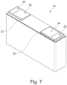
- the battery assembly 10 comprises a total of twelve identical electric battery cells 12 (see also Figure 7 ).
- the electric battery cells 12 are arranged side-by-side along a line-up direction 14.
- the cooling plate 18 comprises a network of internal coolant channels which can be supplied with coolant via a coolant port 18a.
- the cooling plate 18 is arranged on a bottom side of each of the battery cells 12. In other words, all battery cells 12 are located on top of the cooling plate 18.
- the cooling means 16 i.e. the cooling plate 18, is optional.
- the battery cells 12 may be sufficiently cooled via the respective thermal connection surfaces which are arranged on the cell terminals of each battery cell 12 as will be explained below.
- each of the battery cells 12 comprises a first cell terminal 20 and a second cell terminal 22.
- the first cell terminal 20 is electrically connected to an electrode 24. It is understood, that the first cell terminal 20 may also be electrically connected to a plurality of first electrodes. In the representation of Figure 1 , the first electrode 24 is representative of this plurality of electrodes.
- the second cell terminal 22 is electrically connected to an electrode 26. It is understood, that the second cell terminal 22 may also be electrically connected to a plurality of second electrodes. In the representation of Figure 1 , the second electrode 26 is representative of this plurality of electrodes.
- the first cell terminal 20 is a negative terminal which may also be referred to as the minus pole of the electric battery cell 12.
- the first electrodes 24 are anodes.
- the second cell terminal 22 is a positive terminal which may also be referred to as the plus pole of the electric battery cell 12.
- the second electrodes 26 are cathodes.
- the first cell terminal 20 and the second cell terminal 22 are tab-shaped (see especially Figures 1, 2 and 7 ). It is understood that also cell terminals 20, 22 of other shapes are possible, especially pin-shaped cell terminals 20, 22.
- the first cell terminal 20 comprises an electric connection surface 28.
- the second cell terminal 22 comprises an electrical connection surface 30.
- the electric battery cells 12 are connected in series.
- the electric battery cells 12 are arranged in alternating orientations and neighboring first cell terminals 20 and second cell terminals 22 of neighboring electric battery cells 12 are electrically connected via an electric conductor 32 respectively.
- the electric conductor 32 may also be designated a bus bar.
- the electric conductors 32 also form part of the battery assembly 10.
- the battery assembly 10 comprises a total of twelve electric battery cells 12 and a total of thirteen electric conductors 32, the following explanations will be focused on one single electric battery cell 12 and its connections (cf. Figure 2 ).
- One of the electric conductors 32 is electrically connected to the electric connection surface 28 and the electric connection surface 30 respectively, e.g. by spot welding.
- each of the first cell terminal 20 and the second cell terminal 22 comprises a thermal connection surface.
- the thermal connection surface of the first cell terminal 20 is designated with reference sign 34 and the thermal connection surface of the second cell terminal 22 is designated with reference sign 36.
- thermal connection surface 34 of the first cell terminal 20 is separate from the electric connection surface 28 of the first cell terminal 20. This means that the thermal connection surface 34 and the electric connection surface 28 do not overlap.
- thermal connection surface 36 of the second cell terminal 22 is separate from the electric connection surface 30 of the second cell terminal 22. This means that the thermal connection surface 36 and the electric connection surface 30 do not overlap.
- the battery assembly 10 also comprises two coolant channels 38, 40.
- Coolant channel 38 is arranged adjacent to a first end 10a of the upper side of the electric battery cells 12. Moreover, coolant channel 38 is thermally coupled to all the thermal connection surfaces 34, 36 which are arranged proximate to the first end 10a.
- Coolant channel 40 is arranged adjacent to a second end 10b of the upper side of the electric battery cells 12. The second end 10b is opposed to the first end 10a. Coolant channel 40 is thermally coupled to all the thermal connection surfaces 34, 36 which are arranged proximate to the second end 10b.
- the coolant channels 38, 40 are both configured to guide a coolant and are arranged substantially parallel.
- Both coolant channels 38, 40 are made from plastic material.
- the coolant channels 38, 40 do not directly abut against the respective thermal connection surface 34, 36. Rather, on each of the thermal connection surfaces 34, 36 a thermal interface material 42 is provided.
- the objective of using the thermal interface material 42 is to enhance the thermal conductivity of the thermal connection surfaces 34, 36.
- the thermal interface material 42 has a thermal conductivity which exceeds the thermal conductivity of the first cell terminal 20 and the second cell terminal 22.
- a ceramic spacer part 44 is interposed between each of the thermal connection surfaces 34, 36 and the respective coolant channel 38, 40.
- the objective of using such a ceramic spacer part 44 is to electrically isolate the coolant channels 38, 40 from the first cell terminal 20 and the second cell terminal 22 respectively. At the same time, thermal conductivity shall not be hindered. Therefore, an electric conductivity of the first cell terminal 20 and the second cell terminal 22 is at least double the electric conductivity of the ceramic spacer part 44.
- the ceramic spacer part 44 comprises an aluminum nitride material or a silicon nitride material.
- the thermal interface material 42 is a solder material. It is additionally used to mechanically join the ceramic spacer part 44 on the respective thermal connection surface 34, 36. Furthermore, the ceramic spacer part 44 may be connected to the respective coolant channel 38, 40 by soldering.
- the thickness of the thermal interface material 42 and the ceramic spacer part 44 is artificially increased with respect to reality.
- Figure 3 shows an alternative battery assembly 10.
- one cell terminal which can be a first cell terminal 20 or a second cell terminal 22, are represented.
- the electric connection surface 28, 30and the thermal connection surface 34, 36 of the cell terminal 20, 22 are arranged on the same side of the cell terminal 20, 22.
- thermal connection surface 34, 36 is arranged closer to an end of the upper side of the respective electric battery cell 12 than the electric connection surface 28, 30.
- the order of the electric connection surface 28, 30 and the associated thermal connection surface 34, 36 is inversed.
- Figure 4 shows a further alternative battery assembly 10. Again, for the ease of representation, only the surroundings of one cell terminal are represented.
- the cell terminal can be a first cell terminal 20 or a second cell terminal 22.
- the cell terminal 20, 22 is pin-shaped.
- the electric connection surface 28, 30 is arranged on an upper surface of the cell terminal 20, 22.
- the thermal connection surface 34, 36 is arranged on a side which is adjacent to the side on which the electric connection surface 28, 30 is positioned.
- the thermal connection surface 34, 36 is positioned on a lateral side of the cell terminal 20, 22.
- Figure 5 shows a further alternative battery assembly 10. Again, for the ease of representation, only the surroundings of one cell terminal are represented.
- the cell terminal can be a first cell terminal 20 or a second cell terminal 22.
- Figure 6 shows another alternative battery assembly 10. Again, for the ease of representation, only the surroundings of one cell terminal are represented.
- the cell terminal can be a first cell terminal 20 or a second cell terminal 22.
- the example of Figure 6 is similar to the example of Figures 1 and 2 and the example of Figure 3 .
- the cell terminal can be a first cell terminal 20 or a second cell terminal 22.
- thermal connection surfaces 34a, 34b, 36a, 36b are provided on the cell terminal 20, 22.
- the thermal connection surface 34a, 36a and the thermal connection surface 34b, 36b are separate from one another.
- separate coolant channels 38a, 40a and 38b, 40b are provided. They are thermally coupled to the separate thermal connection surface 34a, 36a and 34b, 36b respectively.
- the electric connection surface 28, 30 is arranged between the thermal connection surface 34a, 36a and the thermal connection surface 34b, 36b.
- an electric conductor 32 having a T-shaped cross-section is used.
- This electric conductor 32 contacts the electric connection surface 28, 30 with the foot of the T-shaped cross-section.
- the upper part of the electric conductor 32 covers the coolant channel 38a, 40a and the coolant channel 38b, 40b.
- the electric conductor 32 and the coolant channels 38, 40 are formed integrally. This means that the coolant channel and the electric conductor 32 are portions of the same part. This is illustrated using dashed lines.
Landscapes
- Chemical & Material Sciences (AREA)
- General Chemical & Material Sciences (AREA)
- Electrochemistry (AREA)
- Chemical Kinetics & Catalysis (AREA)
- Engineering & Computer Science (AREA)
- Manufacturing & Machinery (AREA)
- Power Engineering (AREA)
- Mechanical Engineering (AREA)
- Transportation (AREA)
- Life Sciences & Earth Sciences (AREA)
- Sustainable Energy (AREA)
- Sustainable Development (AREA)
- Aviation & Aerospace Engineering (AREA)
- Inorganic Chemistry (AREA)
- Secondary Cells (AREA)
- Battery Mounting, Suspending (AREA)
Claims (12)
- Élément de batterie électrique (12) destiné à un ensemble batterie (10), l'élément de batterie électrique (12) comprenant au moins une première électrode (24) qui est connectée électriquement à une première borne d'élément (20) et une seconde électrode (26) qui est connectée électriquement à une seconde borne d'élément (22),dans lequel chacune de la première borne d'élément (20) et de la seconde borne d'élément (22) comprend une surface de connexion électrique (28, 30) destinée à la connexion électrique de la première borne d'élément (20) ou la seconde borne d'élément (22) respective,caractérisé en ce que au moins une de la première borne d'élément (20) et de la seconde borne d'élément (22) comprend une surface de connexion thermique (34, 36) qui est séparée de la surface de connexion électrique (28, 30) respective, la surface de connexion thermique (34, 36) étant conçue pour transférer de la chaleur, etdans lequel la surface de connexion électrique (28, 30) et la surface de connexion thermique (34, 36) d'au moins une de la première borne d'élément (20) et de la seconde borne d'élément (22) sont agencées sur des côtés adjacents ou opposés de la première borne d'élément (20) ou la seconde borne d'élément (22) respective.
- Élément de batterie électrique (12) selon la revendication 1, dans lequel chacune de la première borne d'élément (20) et de la seconde borne d'élément (22) comprend une surface de connexion thermique (34, 36) qui est conçue pour transférer de la chaleur.
- Élément de batterie électrique (12) selon la revendication 1 ou la revendication 2, dans lequel au moins une de la première borne d'élément (20) et de la seconde borne d'élément (22) comprend deux surfaces de connexion thermique (34, 36) ou plus, qui sont séparées les unes des autres.
- Élément de batterie électrique (12) selon l'une quelconque des revendications 1 à 3, dans lequel un matériau d'interface thermique (42) est agencé sur au moins une surface de connexion thermique (34, 36), une conductivité thermique du matériau d'interface thermique (42) dépassant la conductivité thermique de la première borne d'élément (20) ou de la seconde borne d'élément (22) comprenant la surface de connexion thermique (34, 36) sur laquelle le matériau d'interface thermique (42) est agencé.
- Élément de batterie électrique (12) selon l'une quelconque des revendications 1 à 4, dans lequel une pièce d'écartement en céramique (44) est positionnée sur au moins une surface de connexion thermique (34, 36), une conductivité électrique de la première borne d'élément (20) ou de la seconde borne d'élément (22) sur laquelle la pièce d'écartement en céramique (44) est positionnée étant au moins égale au double de la conductivité électrique de la pièce d'écartement en céramique (44).
- Élément de batterie électrique (12) selon la revendication 5, dans lequel la pièce d'écartement en céramique (44) comprend un matériau à base de nitrure d'aluminium ou un matériau à base de nitrure de silicium.
- Ensemble batterie (10) comprenant
au moins un élément de batterie électrique (12) selon l'une quelconque des revendications 1 à 6, et au moins un canal de refroidissement (38, 40) qui est conçu pour guider un liquide de refroidissement, le canal de refroidissement (38, 40) étant couplé thermiquement à la surface de connexion thermique (34, 36) de l'au moins un élément de batterie électrique (12). - Ensemble batterie (10) selon la revendication 7, dans lequel le canal de refroidissement (38, 40) est en matière plastique.
- Ensemble batterie (10) selon la revendication 7 ou 8, comprenant au moins deux éléments de batterie électrique (12), le canal de refroidissement (38, 40) étant couplé thermiquement aux surfaces de connexion thermique (34, 36) de la totalité des au moins deux éléments de batterie électrique (12).
- Ensemble batterie (10) selon la revendication 9, dans lequel les au moins deux éléments de batterie électrique (12) sont électriquement connectés par un conducteur électrique (32) connectant électriquement une surface de connexion électrique (28, 30) de chacun des au moins deux éléments de batterie électrique (12), le conducteur électrique (32) et le canal de refroidissement (38, 40) étant formés d'un seul tenant.
- Ensemble batterie (10) selon l'une quelconque des revendications 7 à 10, comprenant en outre un moyen de refroidissement (16) qui est agencé sur un côté adjacent ou opposé au côté de l'au moins un élément de batterie électrique (12) portant la première borne d'élément électrique (20) et la seconde borne d'élément électrique (22) respective.
- Véhicule comprenant un ensemble batterie (10) selon l'une quelconque des revendications 7 à 11.
Priority Applications (3)
| Application Number | Priority Date | Filing Date | Title |
|---|---|---|---|
| EP22194249.3A EP4336624B1 (fr) | 2022-09-06 | 2022-09-06 | Ensemble batterie, élément de batterie électrique et véhicule |
| US18/459,900 US20240079680A1 (en) | 2022-09-06 | 2023-09-01 | Battery assembly, electric battery cell, and vehicle |
| CN202311141861.7A CN117673546A (zh) | 2022-09-06 | 2023-09-06 | 电池组件、电池元和车辆 |
Applications Claiming Priority (1)
| Application Number | Priority Date | Filing Date | Title |
|---|---|---|---|
| EP22194249.3A EP4336624B1 (fr) | 2022-09-06 | 2022-09-06 | Ensemble batterie, élément de batterie électrique et véhicule |
Publications (2)
| Publication Number | Publication Date |
|---|---|
| EP4336624A1 EP4336624A1 (fr) | 2024-03-13 |
| EP4336624B1 true EP4336624B1 (fr) | 2024-11-20 |
Family
ID=83232706
Family Applications (1)
| Application Number | Title | Priority Date | Filing Date |
|---|---|---|---|
| EP22194249.3A Active EP4336624B1 (fr) | 2022-09-06 | 2022-09-06 | Ensemble batterie, élément de batterie électrique et véhicule |
Country Status (3)
| Country | Link |
|---|---|
| US (1) | US20240079680A1 (fr) |
| EP (1) | EP4336624B1 (fr) |
| CN (1) | CN117673546A (fr) |
Families Citing this family (1)
| Publication number | Priority date | Publication date | Assignee | Title |
|---|---|---|---|---|
| KR20250137912A (ko) * | 2024-03-12 | 2025-09-19 | 삼성에스디아이 주식회사 | 배터리 모듈 |
Family Cites Families (7)
| Publication number | Priority date | Publication date | Assignee | Title |
|---|---|---|---|---|
| KR20130118145A (ko) * | 2012-04-19 | 2013-10-29 | 삼성에스디아이 주식회사 | 배터리 팩 |
| JP6724785B2 (ja) * | 2014-10-27 | 2020-07-15 | 日本電気株式会社 | 二次電池、電動車両、蓄電システム、および製造方法 |
| KR20180080614A (ko) * | 2017-01-04 | 2018-07-12 | 현대자동차주식회사 | 전기자동차의 수냉식 배터리모듈 |
| GB2570300B (en) * | 2018-01-17 | 2020-11-25 | Siemens Ag | Energy storage system |
| US20210305639A1 (en) * | 2020-03-29 | 2021-09-30 | Global Graphene Group, Inc. | Graphitic film-enabled battery cooling system and method of operating same |
| IL302072A (en) * | 2020-11-03 | 2023-06-01 | Eaglepicher Technologies Llc | Terminal assemblies and methods of using and making the same |
| FR3128318A1 (fr) * | 2021-10-15 | 2023-04-21 | Faurecia Systemes D'echappement | Cellule poche et batterie de stockage d’électricité |
-
2022
- 2022-09-06 EP EP22194249.3A patent/EP4336624B1/fr active Active
-
2023
- 2023-09-01 US US18/459,900 patent/US20240079680A1/en active Pending
- 2023-09-06 CN CN202311141861.7A patent/CN117673546A/zh active Pending
Also Published As
| Publication number | Publication date |
|---|---|
| CN117673546A (zh) | 2024-03-08 |
| US20240079680A1 (en) | 2024-03-07 |
| EP4336624A1 (fr) | 2024-03-13 |
Similar Documents
| Publication | Publication Date | Title |
|---|---|---|
| US9209499B2 (en) | Battery pack | |
| KR102214949B1 (ko) | 전지 팩 | |
| US8568918B2 (en) | Battery having a plurality of single cells | |
| US8124270B2 (en) | Prismatic sealed rechargeable battery, battery module, and battery pack | |
| US8852782B2 (en) | Battery pack having novel structure | |
| US20120244404A1 (en) | Prismatic cell system with thermal management features | |
| US7794870B2 (en) | Battery suitable for preparation of battery module | |
| CN101946343A (zh) | 具有导热板和多个单体的电池 | |
| US20230017033A1 (en) | Battery with integrated bus bar cooling system and motor vehicle | |
| US20200274132A1 (en) | Electrical cell connection arrangements and method thereof | |
| US9461283B2 (en) | Battery module | |
| US20240413428A1 (en) | Motor vehicle and battery with a cooling element | |
| EP4336624B1 (fr) | Ensemble batterie, élément de batterie électrique et véhicule | |
| US7611788B2 (en) | Fuel cell stack | |
| US20190288301A1 (en) | Fuel cell stack, fuel cell stack dummy cell, method of producing dummy cell | |
| US5006427A (en) | Storage battery | |
| CN117996338A (zh) | 电池模组、电池包和车辆 | |
| US20260045646A1 (en) | Battery Module and Battery Pack Including Same | |
| US12015134B2 (en) | Battery unit having cell stack, bus bars, cooler, waterproof plate, and heat transfer member | |
| US12401095B2 (en) | Busbar for a battery | |
| US20260094855A1 (en) | Steel prismatic can construction for improved thermal efficiency | |
| US20250309403A1 (en) | Tab cooling structure and tab cooling structure assembly | |
| US20250350007A1 (en) | Battery module | |
| US20210305547A1 (en) | Contact plate arrangement | |
| CN118589082A (zh) | 牵引电池包热管理系统和方法 |
Legal Events
| Date | Code | Title | Description |
|---|---|---|---|
| PUAI | Public reference made under article 153(3) epc to a published international application that has entered the european phase |
Free format text: ORIGINAL CODE: 0009012 |
|
| STAA | Information on the status of an ep patent application or granted ep patent |
Free format text: STATUS: EXAMINATION IS IN PROGRESS |
|
| 17P | Request for examination filed |
Effective date: 20230601 |
|
| AK | Designated contracting states |
Kind code of ref document: A1 Designated state(s): AL AT BE BG CH CY CZ DE DK EE ES FI FR GB GR HR HU IE IS IT LI LT LU LV MC MK MT NL NO PL PT RO RS SE SI SK SM TR |
|
| GRAP | Despatch of communication of intention to grant a patent |
Free format text: ORIGINAL CODE: EPIDOSNIGR1 |
|
| STAA | Information on the status of an ep patent application or granted ep patent |
Free format text: STATUS: GRANT OF PATENT IS INTENDED |
|
| INTG | Intention to grant announced |
Effective date: 20240627 |
|
| GRAS | Grant fee paid |
Free format text: ORIGINAL CODE: EPIDOSNIGR3 |
|
| GRAA | (expected) grant |
Free format text: ORIGINAL CODE: 0009210 |
|
| STAA | Information on the status of an ep patent application or granted ep patent |
Free format text: STATUS: THE PATENT HAS BEEN GRANTED |
|
| AK | Designated contracting states |
Kind code of ref document: B1 Designated state(s): AL AT BE BG CH CY CZ DE DK EE ES FI FR GB GR HR HU IE IS IT LI LT LU LV MC MK MT NL NO PL PT RO RS SE SI SK SM TR |
|
| REG | Reference to a national code |
Ref country code: GB Ref legal event code: FG4D |
|
| REG | Reference to a national code |
Ref country code: CH Ref legal event code: EP |
|
| REG | Reference to a national code |
Ref country code: DE Ref legal event code: R096 Ref document number: 602022007871 Country of ref document: DE |
|
| REG | Reference to a national code |
Ref country code: IE Ref legal event code: FG4D |
|
| P01 | Opt-out of the competence of the unified patent court (upc) registered |
Free format text: CASE NUMBER: APP_61700/2024 Effective date: 20241119 |
|
| REG | Reference to a national code |
Ref country code: LT Ref legal event code: MG9D |
|
| REG | Reference to a national code |
Ref country code: NL Ref legal event code: MP Effective date: 20241120 |
|
| PG25 | Lapsed in a contracting state [announced via postgrant information from national office to epo] |
Ref country code: HR Free format text: LAPSE BECAUSE OF FAILURE TO SUBMIT A TRANSLATION OF THE DESCRIPTION OR TO PAY THE FEE WITHIN THE PRESCRIBED TIME-LIMIT Effective date: 20241120 Ref country code: PT Free format text: LAPSE BECAUSE OF FAILURE TO SUBMIT A TRANSLATION OF THE DESCRIPTION OR TO PAY THE FEE WITHIN THE PRESCRIBED TIME-LIMIT Effective date: 20250320 Ref country code: IS Free format text: LAPSE BECAUSE OF FAILURE TO SUBMIT A TRANSLATION OF THE DESCRIPTION OR TO PAY THE FEE WITHIN THE PRESCRIBED TIME-LIMIT Effective date: 20250320 |
|
| PG25 | Lapsed in a contracting state [announced via postgrant information from national office to epo] |
Ref country code: NL Free format text: LAPSE BECAUSE OF FAILURE TO SUBMIT A TRANSLATION OF THE DESCRIPTION OR TO PAY THE FEE WITHIN THE PRESCRIBED TIME-LIMIT Effective date: 20241120 Ref country code: FI Free format text: LAPSE BECAUSE OF FAILURE TO SUBMIT A TRANSLATION OF THE DESCRIPTION OR TO PAY THE FEE WITHIN THE PRESCRIBED TIME-LIMIT Effective date: 20241120 |
|
| REG | Reference to a national code |
Ref country code: AT Ref legal event code: MK05 Ref document number: 1744427 Country of ref document: AT Kind code of ref document: T Effective date: 20241120 |
|
| PG25 | Lapsed in a contracting state [announced via postgrant information from national office to epo] |
Ref country code: BG Free format text: LAPSE BECAUSE OF FAILURE TO SUBMIT A TRANSLATION OF THE DESCRIPTION OR TO PAY THE FEE WITHIN THE PRESCRIBED TIME-LIMIT Effective date: 20241120 |
|
| PG25 | Lapsed in a contracting state [announced via postgrant information from national office to epo] |
Ref country code: ES Free format text: LAPSE BECAUSE OF FAILURE TO SUBMIT A TRANSLATION OF THE DESCRIPTION OR TO PAY THE FEE WITHIN THE PRESCRIBED TIME-LIMIT Effective date: 20241120 |
|
| PG25 | Lapsed in a contracting state [announced via postgrant information from national office to epo] |
Ref country code: NO Free format text: LAPSE BECAUSE OF FAILURE TO SUBMIT A TRANSLATION OF THE DESCRIPTION OR TO PAY THE FEE WITHIN THE PRESCRIBED TIME-LIMIT Effective date: 20250220 |
|
| PG25 | Lapsed in a contracting state [announced via postgrant information from national office to epo] |
Ref country code: GR Free format text: LAPSE BECAUSE OF FAILURE TO SUBMIT A TRANSLATION OF THE DESCRIPTION OR TO PAY THE FEE WITHIN THE PRESCRIBED TIME-LIMIT Effective date: 20250221 Ref country code: LV Free format text: LAPSE BECAUSE OF FAILURE TO SUBMIT A TRANSLATION OF THE DESCRIPTION OR TO PAY THE FEE WITHIN THE PRESCRIBED TIME-LIMIT Effective date: 20241120 Ref country code: AT Free format text: LAPSE BECAUSE OF FAILURE TO SUBMIT A TRANSLATION OF THE DESCRIPTION OR TO PAY THE FEE WITHIN THE PRESCRIBED TIME-LIMIT Effective date: 20241120 |
|
| PG25 | Lapsed in a contracting state [announced via postgrant information from national office to epo] |
Ref country code: PL Free format text: LAPSE BECAUSE OF FAILURE TO SUBMIT A TRANSLATION OF THE DESCRIPTION OR TO PAY THE FEE WITHIN THE PRESCRIBED TIME-LIMIT Effective date: 20241120 |
|
| PG25 | Lapsed in a contracting state [announced via postgrant information from national office to epo] |
Ref country code: RS Free format text: LAPSE BECAUSE OF FAILURE TO SUBMIT A TRANSLATION OF THE DESCRIPTION OR TO PAY THE FEE WITHIN THE PRESCRIBED TIME-LIMIT Effective date: 20250220 |
|
| PG25 | Lapsed in a contracting state [announced via postgrant information from national office to epo] |
Ref country code: SM Free format text: LAPSE BECAUSE OF FAILURE TO SUBMIT A TRANSLATION OF THE DESCRIPTION OR TO PAY THE FEE WITHIN THE PRESCRIBED TIME-LIMIT Effective date: 20241120 |
|
| PG25 | Lapsed in a contracting state [announced via postgrant information from national office to epo] |
Ref country code: DK Free format text: LAPSE BECAUSE OF FAILURE TO SUBMIT A TRANSLATION OF THE DESCRIPTION OR TO PAY THE FEE WITHIN THE PRESCRIBED TIME-LIMIT Effective date: 20241120 |
|
| PG25 | Lapsed in a contracting state [announced via postgrant information from national office to epo] |
Ref country code: EE Free format text: LAPSE BECAUSE OF FAILURE TO SUBMIT A TRANSLATION OF THE DESCRIPTION OR TO PAY THE FEE WITHIN THE PRESCRIBED TIME-LIMIT Effective date: 20241120 |
|
| PG25 | Lapsed in a contracting state [announced via postgrant information from national office to epo] |
Ref country code: RO Free format text: LAPSE BECAUSE OF FAILURE TO SUBMIT A TRANSLATION OF THE DESCRIPTION OR TO PAY THE FEE WITHIN THE PRESCRIBED TIME-LIMIT Effective date: 20241120 |
|
| PG25 | Lapsed in a contracting state [announced via postgrant information from national office to epo] |
Ref country code: SK Free format text: LAPSE BECAUSE OF FAILURE TO SUBMIT A TRANSLATION OF THE DESCRIPTION OR TO PAY THE FEE WITHIN THE PRESCRIBED TIME-LIMIT Effective date: 20241120 |
|
| PG25 | Lapsed in a contracting state [announced via postgrant information from national office to epo] |
Ref country code: CZ Free format text: LAPSE BECAUSE OF FAILURE TO SUBMIT A TRANSLATION OF THE DESCRIPTION OR TO PAY THE FEE WITHIN THE PRESCRIBED TIME-LIMIT Effective date: 20241120 |
|
| PG25 | Lapsed in a contracting state [announced via postgrant information from national office to epo] |
Ref country code: IT Free format text: LAPSE BECAUSE OF FAILURE TO SUBMIT A TRANSLATION OF THE DESCRIPTION OR TO PAY THE FEE WITHIN THE PRESCRIBED TIME-LIMIT Effective date: 20241120 |
|
| REG | Reference to a national code |
Ref country code: DE Ref legal event code: R097 Ref document number: 602022007871 Country of ref document: DE |
|
| PG25 | Lapsed in a contracting state [announced via postgrant information from national office to epo] |
Ref country code: SE Free format text: LAPSE BECAUSE OF FAILURE TO SUBMIT A TRANSLATION OF THE DESCRIPTION OR TO PAY THE FEE WITHIN THE PRESCRIBED TIME-LIMIT Effective date: 20241120 |
|
| PLBE | No opposition filed within time limit |
Free format text: ORIGINAL CODE: 0009261 |
|
| STAA | Information on the status of an ep patent application or granted ep patent |
Free format text: STATUS: NO OPPOSITION FILED WITHIN TIME LIMIT |
|
| PGFP | Annual fee paid to national office [announced via postgrant information from national office to epo] |
Ref country code: DE Payment date: 20250820 Year of fee payment: 4 |
|
| PGFP | Annual fee paid to national office [announced via postgrant information from national office to epo] |
Ref country code: FR Payment date: 20250820 Year of fee payment: 4 |
|
| 26N | No opposition filed |
Effective date: 20250821 |