EP4336625A1 - Flüssigkeitskühlleitung und flüssigkeitskühlsystem für energiespeichersystem und energiespeichervorrichtung - Google Patents
Flüssigkeitskühlleitung und flüssigkeitskühlsystem für energiespeichersystem und energiespeichervorrichtung Download PDFInfo
- Publication number
- EP4336625A1 EP4336625A1 EP23802551.4A EP23802551A EP4336625A1 EP 4336625 A1 EP4336625 A1 EP 4336625A1 EP 23802551 A EP23802551 A EP 23802551A EP 4336625 A1 EP4336625 A1 EP 4336625A1
- Authority
- EP
- European Patent Office
- Prior art keywords
- liquid
- outlet
- inlet
- pipe
- main
- Prior art date
- Legal status (The legal status is an assumption and is not a legal conclusion. Google has not performed a legal analysis and makes no representation as to the accuracy of the status listed.)
- Pending
Links
Images


Classifications
-
- H—ELECTRICITY
- H01—ELECTRIC ELEMENTS
- H01M—PROCESSES OR MEANS, e.g. BATTERIES, FOR THE DIRECT CONVERSION OF CHEMICAL ENERGY INTO ELECTRICAL ENERGY
- H01M10/00—Secondary cells; Manufacture thereof
- H01M10/60—Heating or cooling; Temperature control
- H01M10/61—Types of temperature control
- H01M10/613—Cooling or keeping cold
-
- H—ELECTRICITY
- H01—ELECTRIC ELEMENTS
- H01M—PROCESSES OR MEANS, e.g. BATTERIES, FOR THE DIRECT CONVERSION OF CHEMICAL ENERGY INTO ELECTRICAL ENERGY
- H01M10/00—Secondary cells; Manufacture thereof
- H01M10/60—Heating or cooling; Temperature control
- H01M10/62—Heating or cooling; Temperature control specially adapted for specific applications
- H01M10/625—Vehicles
-
- H—ELECTRICITY
- H01—ELECTRIC ELEMENTS
- H01M—PROCESSES OR MEANS, e.g. BATTERIES, FOR THE DIRECT CONVERSION OF CHEMICAL ENERGY INTO ELECTRICAL ENERGY
- H01M10/00—Secondary cells; Manufacture thereof
- H01M10/60—Heating or cooling; Temperature control
- H01M10/65—Means for temperature control structurally associated with the cells
- H01M10/655—Solid structures for heat exchange or heat conduction
- H01M10/6556—Solid parts with flow channel passages or pipes for heat exchange
-
- H—ELECTRICITY
- H01—ELECTRIC ELEMENTS
- H01M—PROCESSES OR MEANS, e.g. BATTERIES, FOR THE DIRECT CONVERSION OF CHEMICAL ENERGY INTO ELECTRICAL ENERGY
- H01M10/00—Secondary cells; Manufacture thereof
- H01M10/60—Heating or cooling; Temperature control
- H01M10/65—Means for temperature control structurally associated with the cells
- H01M10/655—Solid structures for heat exchange or heat conduction
- H01M10/6556—Solid parts with flow channel passages or pipes for heat exchange
- H01M10/6557—Solid parts with flow channel passages or pipes for heat exchange arranged between the cells
-
- H—ELECTRICITY
- H01—ELECTRIC ELEMENTS
- H01M—PROCESSES OR MEANS, e.g. BATTERIES, FOR THE DIRECT CONVERSION OF CHEMICAL ENERGY INTO ELECTRICAL ENERGY
- H01M10/00—Secondary cells; Manufacture thereof
- H01M10/60—Heating or cooling; Temperature control
- H01M10/65—Means for temperature control structurally associated with the cells
- H01M10/656—Means for temperature control structurally associated with the cells characterised by the type of heat-exchange fluid
- H01M10/6567—Liquids
-
- H—ELECTRICITY
- H01—ELECTRIC ELEMENTS
- H01M—PROCESSES OR MEANS, e.g. BATTERIES, FOR THE DIRECT CONVERSION OF CHEMICAL ENERGY INTO ELECTRICAL ENERGY
- H01M10/00—Secondary cells; Manufacture thereof
- H01M10/60—Heating or cooling; Temperature control
- H01M10/65—Means for temperature control structurally associated with the cells
- H01M10/656—Means for temperature control structurally associated with the cells characterised by the type of heat-exchange fluid
- H01M10/6567—Liquids
- H01M10/6568—Liquids characterised by flow circuits, e.g. loops, located externally to the cells or cell casings
-
- H—ELECTRICITY
- H01—ELECTRIC ELEMENTS
- H01M—PROCESSES OR MEANS, e.g. BATTERIES, FOR THE DIRECT CONVERSION OF CHEMICAL ENERGY INTO ELECTRICAL ENERGY
- H01M50/00—Constructional details or processes of manufacture of the non-active parts of electrochemical cells other than fuel cells, e.g. hybrid cells
- H01M50/30—Arrangements for facilitating escape of gases
-
- Y—GENERAL TAGGING OF NEW TECHNOLOGICAL DEVELOPMENTS; GENERAL TAGGING OF CROSS-SECTIONAL TECHNOLOGIES SPANNING OVER SEVERAL SECTIONS OF THE IPC; TECHNICAL SUBJECTS COVERED BY FORMER USPC CROSS-REFERENCE ART COLLECTIONS [XRACs] AND DIGESTS
- Y02—TECHNOLOGIES OR APPLICATIONS FOR MITIGATION OR ADAPTATION AGAINST CLIMATE CHANGE
- Y02E—REDUCTION OF GREENHOUSE GAS [GHG] EMISSIONS, RELATED TO ENERGY GENERATION, TRANSMISSION OR DISTRIBUTION
- Y02E60/00—Enabling technologies; Technologies with a potential or indirect contribution to GHG emissions mitigation
- Y02E60/10—Energy storage using batteries
Definitions
- the present disclosure mainly relates to the field of renewable energy, and specifically relate to a liquid-cooling pipeline, a liquid-cooling system, and an energy storage device.
- the cooling method of energy storage systems is mainly forced air cooling, and a few energy storage systems use liquid-cooling systems to cool battery packs.
- the number of liquid-cooling pipelines required in the energy storage system has increased significantly.
- the cooling pipes connected in series may cause the temperature of the coolant entering each battery pack to be uneven, and gas may easily be generated in the cooling circuit, leading to problems such as large temperature differences between battery packs and local high temperatures, which will affect the life and efficiency of the entire energy storage system.
- Some embodiments of the present disclosure are intended to provide a liquid-cooling pipeline, a liquid-cooling system for an energy storage system, and an energy storage device all of which can improve the temperature uniformity of the cooling pipelines and avoid the generation of gas in the cooling circuit.
- a liquid-cooling pipeline for an energy storage system comprising: an inlet pipeline including a main inlet pipe, at least one battery cluster inlet pipe and at least one battery pack inlet pipe, wherein the main inlet pipe has a liquid inlet and at least one liquid outlet, each battery cluster inlet pipe has a liquid inlet and at least one liquid outlet, each battery pack inlet pipe has a liquid inlet and at least one liquid outlet, each liquid outlet of the main inlet pipe is connected to the liquid inlet of a corresponding cluster inlet pipe, and each liquid outlet of the battery cluster inlet pipe is connected to the liquid inlet of a corresponding battery pack inlet pipe; and an outlet pipeline including a main outlet pipe, at least one battery cluster outlet pipe and at least one battery pack outlet pipe, wherein the main outlet pipe has a liquid outlet and at least one liquid inlet, each battery cluster outlet pipe has a liquid outlet, an exhaust valve located at a top of the battery cluster outlet pipe and at least one liquid inlet
- the liquid-cooling pipeline for an energy storage system further comprises at least two cooling flow channels, wherein each cooling flow channel has a liquid inlet connected to the liquid outlet of the battery pack inlet pipe and a liquid outlet connected to the liquid inlet of the battery pack outlet pipe wherein liquid flow directions in adjacent cooling flow channels are opposite.
- inner diameters of the liquid inlet of the cooling flow channel is less than or equal to an inner diameter of the liquid outlet of the cooling flow channel.
- inner diameters of the at least one liquid outlet of each battery cluster inlet pipe decrease along a liquid flow direction therein.
- each inner diameter of the at least one liquid inlet of the main outlet pipe is not less than a maximum inner diameter of the at least one liquid outlet of the main inlet pipe.
- inner diameters of the at least one liquid outlet of the main inlet pipe increase along the direction of liquid flow.
- the main inlet pipe includes a first main inlet pipe made of flexible material and a second main inlet pipe, and the liquid inlet of the main inlet pipe is located at an end of the first main inlet pipe away from the second main inlet pipe.
- the main outlet pipe includes a first main outlet pipe made of flexible material and a second main outlet pipe, and the liquid outlet of the main outlet pipe is located at an end of the first main outlet pipe away from the second main outlet pipe.
- the present disclosure also proposes a liquid-cooling system for an energy storage system, comprising: a liquid-cooling machine; and the liquid-cooling pipeline, and the liquid-cooling machine is connected to the liquid inlet of the main inlet pipe, and is connected to the liquid outlet of the main outlet pipe.
- the present disclosure also proposes an energy storage device, comprising the liquid-cooling system.
- the liquid-cooling pipeline of the present disclosure can effectively discharge the gas in the liquid and improve the temperature uniformity of the energy storage system by an exhaust valve set at the top of the inlet pipe of each battery cluster.
- the liquid-cooling pipeline of the present disclosure helps to improve the temperature uniformity of the energy storage device by setting the liquid outlet of the liquid main pipe to increase in the liquid flow direction and setting the liquid outlet of the battery cluster inlet pipe to decrease along the liquid flow direction.
- spatial relationship words such as “below”, “below”, “below”, “below”, “above”, “on”, etc. may be used to describe an element shown in the drawings. or the relationship of a feature to other elements or features. It will be understood that these spatially relative terms are intended to encompass other orientations of the device in use or operation in addition to the orientations depicted in the FIGs. For example, if the device in the FIGs. is turned over, elements described as “below” or “under” or “under” other elements or features would then be oriented “above” the other elements or features. Thus, the exemplary words “below” and “below” can encompass both upper and lower directions.
- the device may be otherwise oriented (rotated 90 degrees or at other orientations) and the spatially relative descriptors used herein should be interpreted accordingly. Additionally, it will also be understood that when a layer is referred to as being "between" two layers, it can be the only layer between the two layers, or one or more intervening layers may also be present.
- structures described as having a first feature "on" a second feature may include embodiments in which the first and second features are formed in direct contact, and may also include embodiments in which additional features are formed between the first and second features. Embodiments between second features such that the first and second features may not be in direct contact.
- liquid-cooling system the liquid-cooling system, and the energy storage device of the present disclosure will be described through specific embodiments.
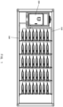
- FIG. 1 shows a schematic structural diagram of a liquid-cooling pipeline and an energy storage device cooled by the liquid-cooling pipeline.
- the energy storage device includes five battery clusters 200.
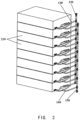
- FIG. 2 is a schematic structural diagram of the dotted box portion in FIG. 1 .
- a battery cluster is composed of eight battery packs 210 stacked in sequence. It can be understood that the number of the battery clusters and the battery packs can be adjusted according to actual needs and is not limited to the above embodiment.
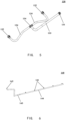
- FIGs. 3 to 5 are schematic structural diagrams of different components in the inlet pipeline according to one embodiment of the present disclosure.
- FIGs. 6 to 8 are schematic structural diagrams of different components in the outlet pipeline according to one embodiment of the present disclosure.
- the liquid-cooling pipeline of the present disclosure will now be described with reference to FIGs. 1 to 8 .
- the liquid-cooling pipeline includes an inlet pipeline and an outlet pipeline.
- the inlet pipeline includes a main inlet pipe 110, five battery cluster inlet pipes 120 and eight battery pack inlet pipes 130.
- the main inlet pipe 110 extends generally along the horizontal direction as a whole.
- the battery cluster inlet pipe 120 extends generally along the vertical direction as a whole, and the battery cluster inlet pipes 120 are arranged at intervals.
- the main inlet pipe 110 has a liquid inlet 111 and five liquid outlets 112.
- the liquid inlet 111 is the inlet of the coolant which enters the main inlet pipe 110 from the liquid inlet 111.
- the liquid inlet 111 can be used to be connected with a liquid output of a coolant input device to input coolant to the main inlet pipe 110.
- the main inlet pipe 110 includes a first main inlet pipe 113 and a second main inlet pipe 114.
- the first main inlet pipe 113 is made of flexible material, and the liquid inlet 111 of the main inlet pipe 110 is located at an end of the first main inlet pipe 113 away from the second main inlet pipe 114.
- the first main inlet pipe 113 is made of flexible material, and the liquid inlet 111 is set at one end of the first main inlet pipe 113, the main inlet pipe 110 is helped to be tightly connected with a liquid output end of the coolant input device, thereby preventing coolant leakage and avoid rupture of the main inlet pipe 110 due to thermal expansion and contraction of the main inlet pipe 110.
- the first main inlet pipe is a rubber hose, and the second main inlet pipe is a metal pipe.
- the main inlet pipe 110 is covered with an insulation layer to prevent condensation.
- the numbers of the liquid outlets of the main inlet pipe can be adjusted according to actual needs.
- five liquid outlets 112 are provided on the main inlet pipe 110.
- the number of liquid outlets 112 can also be other numbers, such as 3, 7 or 8.
- the above embodiments do not constitute a limitation on the number of liquid outlets in the present disclosure. This description is also applicable to the embodiments about numbers below, and will not be repeated.
- the inner diameters of the at least one liquid outlet 112 of the main inlet pipe 110 increase along the liquid flow direction (indicated by arrows in FIG. 3 ). It should be noted that the increasing of the inner diameters of the at least one liquid outlet 112 along the liquid flow direction includes the following situations. One is that the inner diameters of the at least one liquid outlet 112 increase sequentially along the liquid flow direction, conforming to a strict increasing function. Another is that the inner diameters of the at least one liquid outlet 112 increase along the liquid flow direction conforming to an increasing function, but the inner diameters of some adjacent liquid outlets 112 are the same.
- the inner diameters of the part of the liquid outlets 112 close to the liquid inlet 111 of the main inlet pipe 110 are the same, but smaller than the inner diameters of the part of the liquid outlets 112 far away from the liquid inlet 111.
- the flow rate of the coolant may decrease due to friction and other factors.
- FIG. 4 is a schematic structural diagram of a battery cluster inlet pipe according to an embodiment of the present disclosure.
- each battery cluster inlet pipe 120 has a liquid inlet 121 and eight liquid outlets 122.
- each liquid outlet 112 of the main inlet pipe 110 is respectively connected to the liquid inlet 121 of a battery cluster inlet pipe 120.
- the inner diameter of the at least one liquid outlet 122 of the battery cluster inlet pipe 120 decreases along the liquid flow direction (shown by the arrow in FIG. 4 ). It should be noted that similar to “the inner diameters of the at least one liquid outlet 112 of the main inlet pipe 110 decrease along the direction of liquid flow", “the inner diameters of the at least one liquid outlet 121 of the battery cluster inlet pipe 120 decrease along the liquid flow direction” includes both situations of decreasing and strictly decreasing, which will not be described in detail here. Due to factors such as gravity, the flowing speed of coolant grows while flowing from the top of the battery cluster inlet pipe to the bottom of the battery cluster inlet pipe. Setting the inner diameters of the liquid outlet of the battery cluster inlet pipe to decrease along the liquid flow direction helps to improve the temperature uniformity of the liquid-cooling pipeline.
- FIG. 5 is a schematic structural diagram of a battery pack inlet pipe according to an embodiment of the present disclosure.
- each battery pack inlet pipe 130 has a liquid inlet 131 and two liquid outlets 132.
- each liquid outlet 122 of the battery cluster inlet pipe 120 is respectively connected to the liquid inlet 131 of a battery pack inlet pipe 130.
- the battery pack inlet pipe 130 further includes a main pipeline 133 and two branch pipelines 134.
- the first ends of the two branch pipeline 134 are connected to the main pipeline 133 through a tee joint 135, and the two liquid outlets 132 are respectively located at the second ends of the two branch pipelines 134.
- the main pipeline 133 and the two branch pipelines 134 can both be nylon tubes. Nylon tubes have a certain degree of flexibility and are easy to bend and deform, which are especially suitable for complex environments.
- the liquid outlets 112 of the main inlet pipes 110 are respectively connected to the liquid inlets 121 of one battery cluster inlet pipe 120.
- the liquid inlet 121 of the battery cluster inlet pipe 120 is a quick-plug interface which can be quickly connected to the liquid outlet 112 of the main inlet pipe 110.
- the liquid outlets 122 of the battery cluster inlet pipes 120 are respectively connected to the liquid inlets 131 of one battery pack inlet pipes 130.
- the liquid outlets 122 of the battery cluster inlet pipe 120 are implemented as three-way joints, and bellows 123 are connected between the three-way joints.
- the coolant enters the main inlet pipe 110 from the liquid inlet 111 of the main inlet pipe 110, the coolant then flows into the battery cluster inlet pipe 120 from the liquid inlet 121 connected to the liquid inlet outlet 112 of the main inlet pipe 110. The coolant then flows into the battery pack inlet pipe 130 from the liquid inlet 131 connected to the liquid outlet 122 of the battery cluster inlet pipe 120.
- the outlet pipeline includes a main outlet pipe 140, five battery cluster outlet pipes 150, and eight battery pack outlet pipes 160.
- the main outlet pipe 140 extends generally along the horizontal direction.
- the battery cluster outlet pipes 150 generally extend along the vertical direction, and the battery cluster outlet pipes 150 are arranged at intervals.
- FIG. 6 shows a schematic structural diagram of a main outlet pipe according to an embodiment of the present disclosure.
- the main outlet pipe has a liquid outlet 142 and five liquid inlets 141.
- the liquid outlet 142 can be used to connect with the coolant input device to recycle coolant.
- the main outlet pipe 140 includes a first main outlet pipe 143 and a second main outlet pipe 144.
- the first main outlet pipe 143 is made of flexible material.
- the liquid outlet of the main outlet pipe 140 is located at an end of the first main outlet pipe 143 away from the second main outlet pipe 144.
- the main outlet pipe 140 is helped to be tightly connected with the liquid output of the coolant input device, thereby preventing the coolant from leakage and preventing the main outlet pipe 140 from rupture caused by thermal expansion and contraction of the main outlet pipe 140.
- the first main outlet pipe is a rubber hose
- the second main outlet pipe is a metal pipe.
- the main outlet pipe 110 is covered with an insulation layer to prevent condensation from occurring.
- the inner diameters of the least one liquid inlet of the main outlet pipe are not less than the maximum inner diameter of the at least one liquid outlets of the main inlet pipe. In this way, the resistance to coolant return can be reduced.
- FIG. 7 is a schematic structural diagram of a battery cluster outlet pipe according to an embodiment of the present disclosure.
- each battery cluster outlet pipe 150 has a liquid outlet 151, an exhaust valve 152 located at the top of the battery cluster outlet pipe 150, and eight liquid inlets 153.
- the liquid outlet 151 of each battery cluster outlet pipe 150 is connected to a corresponding liquid inlet 141 of the main outlet pipe 140.
- the liquid inlet 141 is a quick-plug interface to facilitate quick connection with the liquid outlet 151. Before the liquid-cooling pipeline works, it is necessary to fill the liquid-cooling pipeline with coolant.
- the embodiment of the present disclosure installs an exhaust valve at the top of each battery cluster inlet pipe, which can effectively discharge the gas remaining in the coolant, thereby avoiding local overheating of the liquid-cooling pipeline caused by the gas remaining in the coolant.
- FIG. 8 is a schematic structural diagram of a battery pack outlet pipe according to an embodiment of the present disclosure.
- Each battery pack outlet pipe 160 has a liquid outlet 161 and two liquid inlets 162.
- the liquid outlet 161 of the battery pack outlet pipe 160 is connected to the liquid inlet 153 of the battery cluster outlet pipe 150.
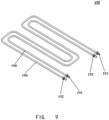
- the liquid-cooling pipeline further includes at least two cooling flow channels.
- each cooling flow channel 190 has a liquid inlet 191 and a liquid outlet 192.
- the liquid inlet 191 is connected to the liquid outlet 132 of the battery pack inlet pipe 130
- the liquid outlet 192 is connected to the liquid inlet 162 of the battery pack outlet pipe 160
- the flow direction of the coolant in adjacent cooling channels 190 is opposite.
- the cooling flow channel 190 is provided inside the battery pack 210, and the coolant flowing through the cooling channel 190 dissipates heat from the battery pack 210.
- the inner diameter of the liquid inlet is larger than the inner diameter of the liquid outlet of the cooling flow channel.
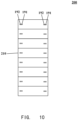
- FIG. 10 is a schematic front view of a battery cluster according to an embodiment of the present disclosure. In order to facilitate understanding of the settings of the inner diameters of the liquid inlet and the liquid outlet of the cooling flow channel in the present disclosure, a non-limiting example is given here.
- the battery cluster 200 has eight battery packs 210 stacked in sequence. Each battery pack has two cooling flow channels, the liquid inlet 191 and the liquid outlet 192 of the cooling flow channel 190 is located outside the battery pack 210.
- the coolant enters the cooling flow channel in the battery pack 210 from the liquid inlet 191 and flows out from the liquid outlet 192.
- the inner diameters of the liquid inlet 191 and the liquid outlet 192 of the cooling flow channel 190 in the four battery packs 210 located at the upper part of the battery cluster 200 are consistent.
- the inner diameter of the liquid outlet 192 of the middle two battery packs 210 is consistent with the inner diameter of the liquid outlet 192 of the cooling flow channel 190 in the four battery packs 210 located at the upper part of the battery cluster 200, and the inner diameter of the liquid inlet 191 of the middle two battery packs is less than the inner diameter of the liquid outlet 192 of the middle two battery packs.
- the inner diameter of the liquid inlet 191 in the lowermost two of battery packs 210 is consistent with the inner diameter of the liquid outlet 192, and the inner diameter is consistent with the inner diameter of the liquid inlet 191 of the middle two of battery packs 210, it helps ensure the temperature uniformity of the battery pack.
- the coolant entering the main inlet pipe 110 from the liquid inlet 111 of the main inlet pipe 110 first flows through the battery cluster inlet pipe 120, then flows to the battery pack inlet pipe 130, and enters the cooling flow channel 190 through the liquid inlet 191 of the cooling flow channel 190 connected to the battery pack inlet pipe 120 to cool the battery pack 210. Subsequently, the coolant flows out from the cooling pipe 190 into the battery pack outlet pipe 160, then enters the main outlet pipe 140 through the battery cluster outlet pipe 150, and finally flow out through the liquid outlet 141 of the main outlet pipe 140.
- the liquid outlet of the main outlet pipe is configured to increase in the direction of liquid flow
- the liquid outlet of the battery cluster inlet pipe is configured to decrease in the direction of liquid flow, which is beneficial to improve the temperature uniformity of liquid-cooling pipelines.
- the gas in the liquid can be effectively discharged and the temperature uniformity of the liquid-cooling pipeline can thus be improved by installing the exhaust valve at the top of the battery cluster inlet pipe.
- the present disclosure also provides a liquid-cooling system for an energy storage system.
- the liquid-cooling system includes the liquid-cooling pipeline as mentioned above and a liquid-cooling machine 220.
- the liquid-cooling machine 220 is connected to the liquid inlet of the main inlet pipe and the liquid outlet of the main outlet pipe.
- the above-mentioned liquid-cooling machine can provide power for the coolant, and on the other hand, it can reduce the temperature of the coolant.
- the present disclosure also provides an energy storage device including the liquid-cooling system as mentioned above.
- the liquid-cooling system and energy storage device used in the energy storage device of the present disclosure have the effect of improving the temperature uniformity of the cooling pipeline.
- numbers are used to describe the quantities of components and properties. It should be understood that such numbers used to describe the embodiments are modified by the modifiers "about”, “approximately” or “substantially” in some examples. Grooming. Unless otherwise stated, “about,” “approximately,” or “substantially” means that the stated number is allowed to vary by ⁇ 20%. Accordingly, in some embodiments, the numerical parameters used in the specification and claims are approximations that may vary depending on the desired features of the individual embodiment. In some embodiments, numerical parameters should account for the specified number of significant digits and use general digit preservation methods. Although the numerical fields and parameters used to confirm the breadth of the ranges in some embodiments of the present application are approximations, in specific embodiments, such numerical values are set as accurately as feasible.
Landscapes
- Chemical & Material Sciences (AREA)
- Chemical Kinetics & Catalysis (AREA)
- Electrochemistry (AREA)
- General Chemical & Material Sciences (AREA)
- Engineering & Computer Science (AREA)
- Manufacturing & Machinery (AREA)
- Secondary Cells (AREA)
- Separation By Low-Temperature Treatments (AREA)
- Physical Or Chemical Processes And Apparatus (AREA)
Applications Claiming Priority (2)
| Application Number | Priority Date | Filing Date | Title |
|---|---|---|---|
| CN202221164116.5U CN217606896U (zh) | 2022-05-12 | 2022-05-12 | 用于储能系统的液冷管路、液冷系统以及储能设备 |
| PCT/CN2023/086381 WO2023216775A1 (zh) | 2022-05-12 | 2023-04-06 | 用于储能系统的液冷管路、液冷系统以及储能设备 |
Publications (2)
| Publication Number | Publication Date |
|---|---|
| EP4336625A1 true EP4336625A1 (de) | 2024-03-13 |
| EP4336625A4 EP4336625A4 (de) | 2024-08-28 |
Family
ID=83569705
Family Applications (1)
| Application Number | Title | Priority Date | Filing Date |
|---|---|---|---|
| EP23802551.4A Pending EP4336625A4 (de) | 2022-05-12 | 2023-04-06 | Flüssigkeitskühlleitung und flüssigkeitskühlsystem für energiespeichersystem und energiespeichervorrichtung |
Country Status (5)
| Country | Link |
|---|---|
| US (1) | US20240380027A1 (de) |
| EP (1) | EP4336625A4 (de) |
| CN (1) | CN217606896U (de) |
| AU (1) | AU2023266704A1 (de) |
| WO (1) | WO2023216775A1 (de) |
Families Citing this family (6)
| Publication number | Priority date | Publication date | Assignee | Title |
|---|---|---|---|---|
| CN217606896U (zh) * | 2022-05-12 | 2022-10-18 | 江苏天合储能有限公司 | 用于储能系统的液冷管路、液冷系统以及储能设备 |
| CN116014301A (zh) * | 2022-12-30 | 2023-04-25 | 北京海博思创科技股份有限公司 | 液冷系统及储能集装箱 |
| CN115911668A (zh) * | 2023-02-23 | 2023-04-04 | 惠州亿纬锂能股份有限公司 | 一种液冷系统及电池包 |
| CN116197669A (zh) * | 2023-03-22 | 2023-06-02 | 广东钶锐锶数控技术股份有限公司 | 一种五轴车铣复合加工中心设备 |
| CN116706340B (zh) * | 2023-08-09 | 2023-10-27 | 江苏天合储能有限公司 | 储能系统热管理方法及其系统、电子设备、存储介质 |
| WO2025213349A1 (zh) * | 2024-04-08 | 2025-10-16 | 宁德时代新能源科技股份有限公司 | 储能装置和能源系统 |
Family Cites Families (13)
| Publication number | Priority date | Publication date | Assignee | Title |
|---|---|---|---|---|
| CN105518929B (zh) * | 2013-09-06 | 2018-04-20 | 日产自动车株式会社 | 电池组冷却系统 |
| WO2017033412A1 (ja) * | 2015-08-27 | 2017-03-02 | 三洋電機株式会社 | バッテリシステム及びバッテリシステムを備える電動車両 |
| CN206471459U (zh) * | 2017-01-24 | 2017-09-05 | 铜陵市沃特玛电池有限公司 | 一种电池组散热结构 |
| CN209016205U (zh) * | 2018-11-20 | 2019-06-21 | 宁德时代新能源科技股份有限公司 | 电池包冷却系统及电池包 |
| CN212157709U (zh) * | 2020-06-02 | 2020-12-15 | 巩义市京华仪器有限责任公司 | 一种水冷低温冷却循环装置 |
| CN113097605A (zh) * | 2021-03-31 | 2021-07-09 | 阳光三星(合肥)储能电源有限公司 | 一种电池储能系统 |
| CN215955362U (zh) * | 2021-07-28 | 2022-03-04 | 中航锂电科技有限公司 | 一种液冷系统与电池包 |
| CN215731961U (zh) * | 2021-08-03 | 2022-02-01 | 上海兰钧新能源科技有限公司 | 一种电池柜 |
| CN216161800U (zh) * | 2021-09-02 | 2022-04-01 | 瑞浦能源有限公司 | 储能电池热管理系统 |
| CN216120462U (zh) * | 2021-09-06 | 2022-03-22 | 浙江国创热管理科技有限公司 | 一种储能电池包的热管理系统 |
| CN216354424U (zh) * | 2021-11-12 | 2022-04-19 | 宁德时代新能源科技股份有限公司 | 用于储能装置的热管理系统和储能装置 |
| CN114284593B (zh) * | 2021-12-17 | 2023-07-14 | 重庆长安汽车股份有限公司 | 一种智能调节动力电池温度的热管理系统 |
| CN217606896U (zh) * | 2022-05-12 | 2022-10-18 | 江苏天合储能有限公司 | 用于储能系统的液冷管路、液冷系统以及储能设备 |
-
2022
- 2022-05-12 CN CN202221164116.5U patent/CN217606896U/zh active Active
-
2023
- 2023-04-06 AU AU2023266704A patent/AU2023266704A1/en active Pending
- 2023-04-06 EP EP23802551.4A patent/EP4336625A4/de active Pending
- 2023-04-06 WO PCT/CN2023/086381 patent/WO2023216775A1/zh not_active Ceased
- 2023-04-06 US US18/691,705 patent/US20240380027A1/en active Pending
Also Published As
| Publication number | Publication date |
|---|---|
| EP4336625A4 (de) | 2024-08-28 |
| US20240380027A1 (en) | 2024-11-14 |
| WO2023216775A1 (zh) | 2023-11-16 |
| CN217606896U (zh) | 2022-10-18 |
| AU2023266704A1 (en) | 2023-12-21 |
Similar Documents
| Publication | Publication Date | Title |
|---|---|---|
| US20240380027A1 (en) | Liquid cooling pipeline and liquid cooling system for energy storage system, and energy storage apparatus | |
| CN209119276U (zh) | 动力电池系统的冷却装置、动力电池系统及车辆 | |
| CN217788556U (zh) | 一种液冷系统及电池包 | |
| US10991996B2 (en) | Battery heat exchange system | |
| CN110474119B (zh) | 一种锂离子电池组热管理系统及其热管理方法 | |
| CN216354424U (zh) | 用于储能装置的热管理系统和储能装置 | |
| CN108352476A (zh) | 蓄能器装置 | |
| CN103217048A (zh) | 用于电池冷却系统的塑料液体热交换器 | |
| CN116014301A (zh) | 液冷系统及储能集装箱 | |
| WO2024230029A1 (zh) | 管路连接组件、液冷系统、电池及用电装置 | |
| CN117989895A (zh) | 换热管、电池和用电装置 | |
| CN219303782U (zh) | 液冷系统及储能集装箱 | |
| CN107464965B (zh) | 一种电池包及电池包液冷冷却系统 | |
| CN209029509U (zh) | 一种基于相变材料和热管协同散热的电池模组热管理装置 | |
| CN109273797B (zh) | 一种基于相变材料和热管协同散热的电池模组热管理装置 | |
| CN205004415U (zh) | 一种换热装置 | |
| CN220692129U (zh) | 电芯换热系统及动力电池 | |
| CN103868372B (zh) | 地温热交换系统及其地温热能发电与地温热泵系统 | |
| CN104167397A (zh) | 一种集成散热晶闸管 | |
| CN219611723U (zh) | 一种光伏组件及散热系统 | |
| CN214099710U (zh) | 一种纯电动汽车动力电池用整体式冷却板 | |
| CN117647134A (zh) | 一种瞬时高效的储热式相变换热器 | |
| CN110471513A (zh) | 一种散热器组件、风冷散热器以及空调设备 | |
| CN211045653U (zh) | 一种锂离子电池组热管理系统 | |
| CN220492020U (zh) | 电池包冷却装置、电池管理系统及电动工程机械 |
Legal Events
| Date | Code | Title | Description |
|---|---|---|---|
| STAA | Information on the status of an ep patent application or granted ep patent |
Free format text: STATUS: THE INTERNATIONAL PUBLICATION HAS BEEN MADE |
|
| PUAI | Public reference made under article 153(3) epc to a published international application that has entered the european phase |
Free format text: ORIGINAL CODE: 0009012 |
|
| STAA | Information on the status of an ep patent application or granted ep patent |
Free format text: STATUS: REQUEST FOR EXAMINATION WAS MADE |
|
| 17P | Request for examination filed |
Effective date: 20231204 |
|
| AK | Designated contracting states |
Kind code of ref document: A1 Designated state(s): AL AT BE BG CH CY CZ DE DK EE ES FI FR GB GR HR HU IE IS IT LI LT LU LV MC ME MK MT NL NO PL PT RO RS SE SI SK SM TR |
|
| A4 | Supplementary search report drawn up and despatched |
Effective date: 20240726 |
|
| RIC1 | Information provided on ipc code assigned before grant |
Ipc: H01M 50/30 20210101ALI20240722BHEP Ipc: H01M 10/6568 20140101ALI20240722BHEP Ipc: H01M 10/613 20140101AFI20240722BHEP |
|
| DAV | Request for validation of the european patent (deleted) | ||
| DAX | Request for extension of the european patent (deleted) |