EP4336718A1 - Schaltwandler mit teilleistungsverarbeitung - Google Patents
Schaltwandler mit teilleistungsverarbeitung Download PDFInfo
- Publication number
- EP4336718A1 EP4336718A1 EP22194777.3A EP22194777A EP4336718A1 EP 4336718 A1 EP4336718 A1 EP 4336718A1 EP 22194777 A EP22194777 A EP 22194777A EP 4336718 A1 EP4336718 A1 EP 4336718A1
- Authority
- EP
- European Patent Office
- Prior art keywords
- voltage
- bus
- branch
- output
- circuit
- Prior art date
- Legal status (The legal status is an assumption and is not a legal conclusion. Google has not performed a legal analysis and makes no representation as to the accuracy of the status listed.)
- Pending
Links
Images

Classifications
-
- H—ELECTRICITY
- H02—GENERATION; CONVERSION OR DISTRIBUTION OF ELECTRIC POWER
- H02M—APPARATUS FOR CONVERSION BETWEEN AC AND AC, BETWEEN AC AND DC, OR BETWEEN DC AND DC, AND FOR USE WITH MAINS OR SIMILAR POWER SUPPLY SYSTEMS; CONVERSION OF DC OR AC INPUT POWER INTO SURGE OUTPUT POWER; CONTROL OR REGULATION THEREOF
- H02M1/00—Details of apparatus for conversion
- H02M1/0067—Converter structures employing plural converter units, other than for parallel operation of the units on a single load
- H02M1/007—Plural converter units in cascade
-
- H—ELECTRICITY
- H02—GENERATION; CONVERSION OR DISTRIBUTION OF ELECTRIC POWER
- H02M—APPARATUS FOR CONVERSION BETWEEN AC AND AC, BETWEEN AC AND DC, OR BETWEEN DC AND DC, AND FOR USE WITH MAINS OR SIMILAR POWER SUPPLY SYSTEMS; CONVERSION OF DC OR AC INPUT POWER INTO SURGE OUTPUT POWER; CONTROL OR REGULATION THEREOF
- H02M1/00—Details of apparatus for conversion
- H02M1/0083—Converters characterised by their input or output configuration
-
- H—ELECTRICITY
- H02—GENERATION; CONVERSION OR DISTRIBUTION OF ELECTRIC POWER
- H02M—APPARATUS FOR CONVERSION BETWEEN AC AND AC, BETWEEN AC AND DC, OR BETWEEN DC AND DC, AND FOR USE WITH MAINS OR SIMILAR POWER SUPPLY SYSTEMS; CONVERSION OF DC OR AC INPUT POWER INTO SURGE OUTPUT POWER; CONTROL OR REGULATION THEREOF
- H02M3/00—Conversion of DC power input into DC power output
- H02M3/22—Conversion of DC power input into DC power output with intermediate conversion into AC
- H02M3/24—Conversion of DC power input into DC power output with intermediate conversion into AC by static converters
- H02M3/28—Conversion of DC power input into DC power output with intermediate conversion into AC by static converters using discharge tubes with control electrode or semiconductor devices with control electrode to produce the intermediate AC
- H02M3/325—Conversion of DC power input into DC power output with intermediate conversion into AC by static converters using discharge tubes with control electrode or semiconductor devices with control electrode to produce the intermediate AC using devices of a triode or a transistor type requiring continuous application of a control signal
- H02M3/335—Conversion of DC power input into DC power output with intermediate conversion into AC by static converters using discharge tubes with control electrode or semiconductor devices with control electrode to produce the intermediate AC using devices of a triode or a transistor type requiring continuous application of a control signal using semiconductor devices only
- H02M3/33569—Conversion of DC power input into DC power output with intermediate conversion into AC by static converters using discharge tubes with control electrode or semiconductor devices with control electrode to produce the intermediate AC using devices of a triode or a transistor type requiring continuous application of a control signal using semiconductor devices only having several active switching elements
- H02M3/33576—Conversion of DC power input into DC power output with intermediate conversion into AC by static converters using discharge tubes with control electrode or semiconductor devices with control electrode to produce the intermediate AC using devices of a triode or a transistor type requiring continuous application of a control signal using semiconductor devices only having several active switching elements having at least one active switching element at the secondary side of an isolation transformer
- H02M3/33592—Conversion of DC power input into DC power output with intermediate conversion into AC by static converters using discharge tubes with control electrode or semiconductor devices with control electrode to produce the intermediate AC using devices of a triode or a transistor type requiring continuous application of a control signal using semiconductor devices only having several active switching elements having at least one active switching element at the secondary side of an isolation transformer having a synchronous rectifier circuit or a synchronous freewheeling circuit at the secondary side of an isolation transformer
-
- H—ELECTRICITY
- H02—GENERATION; CONVERSION OR DISTRIBUTION OF ELECTRIC POWER
- H02M—APPARATUS FOR CONVERSION BETWEEN AC AND AC, BETWEEN AC AND DC, OR BETWEEN DC AND DC, AND FOR USE WITH MAINS OR SIMILAR POWER SUPPLY SYSTEMS; CONVERSION OF DC OR AC INPUT POWER INTO SURGE OUTPUT POWER; CONTROL OR REGULATION THEREOF
- H02M1/00—Details of apparatus for conversion
- H02M1/0067—Converter structures employing plural converter units, other than for parallel operation of the units on a single load
- H02M1/0077—Plural converter units whose outputs are connected in series
-
- H—ELECTRICITY
- H02—GENERATION; CONVERSION OR DISTRIBUTION OF ELECTRIC POWER
- H02M—APPARATUS FOR CONVERSION BETWEEN AC AND AC, BETWEEN AC AND DC, OR BETWEEN DC AND DC, AND FOR USE WITH MAINS OR SIMILAR POWER SUPPLY SYSTEMS; CONVERSION OF DC OR AC INPUT POWER INTO SURGE OUTPUT POWER; CONTROL OR REGULATION THEREOF
- H02M1/00—Details of apparatus for conversion
- H02M1/42—Circuits or arrangements for compensating for or adjusting power factor in converters or inverters
-
- Y—GENERAL TAGGING OF NEW TECHNOLOGICAL DEVELOPMENTS; GENERAL TAGGING OF CROSS-SECTIONAL TECHNOLOGIES SPANNING OVER SEVERAL SECTIONS OF THE IPC; TECHNICAL SUBJECTS COVERED BY FORMER USPC CROSS-REFERENCE ART COLLECTIONS [XRACs] AND DIGESTS
- Y02—TECHNOLOGIES OR APPLICATIONS FOR MITIGATION OR ADAPTATION AGAINST CLIMATE CHANGE
- Y02B—CLIMATE CHANGE MITIGATION TECHNOLOGIES RELATED TO BUILDINGS, e.g. HOUSING, HOUSE APPLIANCES OR RELATED END-USER APPLICATIONS
- Y02B70/00—Technologies for an efficient end-user side electric power management and consumption
- Y02B70/10—Technologies improving the efficiency by using switched-mode power supplies [SMPS], i.e. efficient power electronics conversion e.g. power factor correction or reduction of losses in power supplies or efficient standby modes
Definitions
- the present disclosure relates to the field of switching converters that employ a partial power architecture to enable partial power processing.
- Partial Power Processing has proven to be an attractive solution regarding power converter downsizing and efficiency improvement. Furthermore, the advantages that PPP offers are very suitable for applications, such as, energy storage systems (ESS) connected to renewable sources as well as electric vehicle (EV) fast charging stations.
- ESS energy storage systems
- EV electric vehicle
- Partial Power (PP) converters are usually DC/DC converters, wherein the input DC voltage (DC bus voltage) may be provided by an additional AC/DC converter, which may perform Power Factor Correction (PFC).
- PP converters may employ, for example, a resonant LLC converter architecture (see, e.g. Infineon, Application Note AN 2012-09, cl.0, Sept. 2012 ) which is widely used in battery charger applications.
- Resonant CLLC converter architectures are also commonly used.
- a PP converter has usually two branches, one of which (i.e. the main branch) operates as a so-called (resonant) DC transformer (DCX) having a fixed conversion ratio, while the other branch (i.e. the PP branch) may include a regulator that is capable of regulating the output voltage to a desired level.
- DCX DC transformer
- the losses associated with the output voltage regulation accrue only in the PP branch which processes only a small fraction of the total output power of the PP converter.
- the DC bus voltage may be several hundred volts, e.g. 750 V, wherein the battery voltage may vary in a relatively wide range such as, for example, 250 to 450 V, dependent on the state of charge (SoC) of the battery. Accordingly, the PP converter of a battery charger needs to be able to regulate the output voltage in a relatively wide range (e.g. 350 V ⁇ 100 V in the present example).
- SoC state of charge
- the wide output voltage range may require the use of transistor full-bridges with power transistors with a correspondingly high breakdown voltage (e.g. 150 V or more).
- the inventor identified the need for improvements
- the circuit includes a first converter stage configured to provide a DC bus voltage and a second converter stage configured to receive the DC bus voltage and to generate an output voltage therefrom.
- the second converter stage includes at least a main branch and a partial power branch, wherein the main branch is configured to provide, at its output, a first voltage from the DC bus voltage based on a fixed conversion ratio and the partial power branch is configured to provide, at its output, an adjustable second voltage from the DC bus voltage.
- the outputs of the main branch and the partial power branch are connected in series to provide the output voltage.
- the circuit further includes a controller configured to control, in order to set the output voltage, the first converter stage to adjust the DC bus voltage and to control the partial power branch to adjust the second voltage.
- the method includes generating a DC bus voltage using a first converter stage and generating, using a second converter stage, an output voltage from the DC bus voltage, wherein the second converter stage includes at least a main branch and a partial power branch.
- generating the output voltage includes generating a first voltage from the DC bus voltage using a DC transformer circuit with a fixed conversion ratio arranged in the main branch and generating a second voltage from the DC bus voltage in the partial power branch, wherein the first voltage and the second voltage are superposed to generate the output voltage.
- the DC bus voltage and the second voltage are both adjusted such that the output voltage is set in accordance with a desired value.
- Fig. 1 illustrates one example of a power converter circuit which may be used in a battery charger application.
- the power converter circuit is composed of a first converter stage 10, which generates a DC bus voltage V BUS from an AC input voltage V GRID , and a second converter stage 20, which is a DC/DC converter that generates the output voltage V BAT (applied to the battery 30) from the DC bus voltage V BUS .
- the battery 30 may be a lithium-ion battery or any other type of battery dependent on the application.
- the first converter stage 10 may include an (optional) filter circuit 11 for eliminating voltage or current spikes due to electromagnetic interference (EMI) and a PFC converter stage 12, which usually has a boost converter topology. Suitable PFC converters are as such known and thus not discussed herein in greater detail.
- the PFC converter stage 12 is configured to generate the DC bus voltage V BUS .
- the second converter stage 20 may be a DC/DC converter which may use an LLC or a CLLC topology.
- the DC/DC converter 20 includes an inverter 21 (e.g. a transistor full-bridge), a transformer circuit 22 that includes a transformer and one or more inductances (L) and capacitances (C), and a rectifier circuit 23, which may include another transistor full-bridge configured to perform an active rectification.
- the transformer circuit 22 may be operated at a resonance frequency.
- Suitable LLC/CLLC converters are as such known and thus not discussed herein in greater detail. It should, however, be noted that other converter topologies (different from resonant LLC/CLLC converters) may also be used and the embodiments described herein are not limited with regard to the circuit topology of the DC/DC converter.
- Fig. 2 illustrates an example of the second converter stage 20 (DC/DC converter).
- the converter 20 is a Partial Power (PP) converter that includes two branches, which are referred to as main branch and PP branch. Most of the output voltage (and output power) of the PP converter is provided by the main branch (e.g. more than 75% of the input power), while the remaining power is provided by the PP branch. In order to achieve a high efficiency, it is desired to keep the fraction of the power processed by the PP branch low.
- PP Partial Power
- the main branch includes the transistor full bridge 21 operating as inverter, the transformer circuit 22 (e.g. an CLLC circuit as mentioned above), and the transistor full bridge 23 operating as active rectifier.
- the transistor full bridge 23 may be replaced by a passive full-bridge rectifier composed of diodes.
- the output voltage of the main branch i.e. the output voltage of the rectifier 23
- V MP the output voltage of the rectifier 23
- C MP the buffer capacitor C MP that is coupled to the output of the active rectifier 23.
- the operation of the inverter 21 and the active rectifier 23 is controlled by a controller (not shown in Fig. 2 ) such that the transformer circuit 22 is operated at its resonance frequency and that the main branch provides a fixed DC/DC conversion ratio V MP /V BUS .
- a controller not shown in Fig. 2
- the transformer circuit 22 is operated at its resonance frequency and that the main branch provides a fixed DC/DC conversion ratio V MP /V BUS .
- the PP branch includes the inverter 21 (which is also part of the main branch), the transformer circuit 42, and the transistor full bridge 43 operating as active rectifier.
- the transformer circuit 42 may have the same topology as the transformer circuit 22.
- the active rectifier 43 may be replaced by a passive diode full-bridge rectifier.
- the output voltage V PP of the rectifier circuit 43 is buffered by a buffer capacitor C PP coupled to the output of the rectifier circuit 43.
- the DC transformer circuits (DCX) in both branches i.e. inverter 21, transformer network 22 and rectifier 23 in the main branch and inverter 21, transformer network 42 and rectifier 43 in the PP branch
- DC transformers (DCX) are DC/DC converters operating with a fixed conversion ratio (ratio between DC output voltage and DC input voltage of the DCX).
- the operation of components of the PP branch may be controlled using the same controller that controls the operation of the components of the main branch such that the transformer circuit 42 is operated at its resonance frequency and that the PP branch provides a fixed DC/DC conversion ratio V PP /V BUS .
- the output voltage V R of the PP branch is generated from the voltage V PP by a regulated DC/DC converter 44 (also referred to as post-regulator or output stage), which is configured to provide the regulated output voltage V R .
- the output stage 44 may be implemented, e.g. as a buckconverter.
- the voltage V R is buffered by a buffer capacitor C R coupled to the output of the post-regulator 44.
- the outputs of the main branch and the PP branch are coupled in series, so that the total output voltage V BAT of the PP converter equals the sum V MP +V R .
- the PP converter 20 of Fig. 2 may be used as second stage in the battery charger of Fig. 1 .
- the bus voltage V BUS is substantially constant.
- the regulation of the output voltage V BAT is accomplished by the post regulator 44 of the PP branch of the PP converter 20. This is consistent with the general idea of Partial Power Processing, according to which the power/voltage regulation is done in the PP branch of the PP converter to keep the losses associated with the power/voltage regulation low (because the PP branch carries only a small fraction of the total power).
- the bus voltage V BUS is assumed to be at its nominal value of 385 V resulting in a main branch output voltage V MP of 350 V (i.e. the conversion ratio is 0.9 in the present example).
- the desired output voltage range (of V BAT ) is from 250 V to 450 V.
- the PP branch must be designed to provide a regulated output voltage V R in the range from -100 V to +100 V.
- the ratio P PP /P IN 0,22 means that 22 percent of the total power are processed in the PP branch. Reducing the ratio would entail a respective reduction of the output voltage range.
- the fraction of power (P PP /P IN ) processed in the PP branch should be low for a good efficiency.
- the breakdown voltage of the transistors used in the post regulator must be relatively high in the present example.
- V R a typical design choice would be MOSFETs with a breakdown voltage of 150 V.
- Efficiency could be further increased when MOSFETs with a lower breakdown voltage (e.g. 80 V or 100 V) are used in the post-regulator 44.
- this would entail a reduction of the output voltage range, which would make the overall circuit unsuitable for specific applications.
- the examples discussed below address this conflict of objectives.
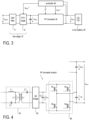
- Fig. 3 The example of Fig. 3 is basically the same as in Fig. 1 , wherein the PP converter of Fig. 2 is used as second stage 20. Thus, reference is made to the explanations above.
- a controller 50 is shown in Fig. 3 , which is configured to control the operation of the PP converter 20, which includes, inter alia, providing a set-point value V BAT ⁇ for the output voltage V BAT .
- the controller 50 can adjust/modulate the bus voltage V BUS (by providing a respective set-point value V BUS ⁇ to the PFC converter 12) dependent on the output voltage V BAT (e.g. dependent on the set-point value V BAT ⁇ )
- the controller 50 can adjust the bus voltage V BUS in the present example dependent on the total output voltage V BAT (or the corresponding set-point value V BAT ⁇ ).
- the bus voltage V BUS is not constant at 385 V but can be varied from, e.g. 340 V to 430 V resulting in a main branch output voltage V MP ranging from 306 V to 387 V (again, the conversion rate is 0.9 in the main branch).
- the desired output voltage range (of V BAT ) is from 250 V to 450 V.
- the required output voltage range (V R ) of the PP branch can be reduced ⁇ 63 V without reducing the range of the total output voltage V BAT when the controller 50 (together with the PFC controller 12) is configured to adjust the bus voltage V BUS .
- the post-regulator may be implemented with transistors that have a lower breakdown voltage (e.g. 80 V or 100 V) as compared to the previous example, in which the bus voltage V BUS is fixed.
- Fig. 4 illustrates a modification of the PP converter of Fig. 2 , in which the post regulator is implemented as a simple transistor H-bridge composed of transistors M 1 , M 2 , M 3 , and M 4 .
- the transistors M 1 and M 3 form a first transistor half bridge, and the transistors M 2 and M 4 form a second transistor half bridge.
- the transistors may be implemented as (e.g. Si or GaN) Metal-on-Semiconductor (MOS) field effect transistors (FETs) or the like.
- MOS transistors may have an intrinsic diode in parallel to the MOS channel (not shown in Fig. 4 ), whereas additionally dedicated free-wheeling diodes may be coupled to the transistors.
- the PP branch includes the inverter 21 (which is also part of the main branch, not shown in Fig. 4 ), the transformer circuit 42, and the transistor full bridge 43 operating as active rectifier.
- the output voltage V PP of the rectifier circuit 43 is buffered by a buffer capacitor C PP coupled to the output of the rectifier circuit 43.
- the post regulator 44 receives the output voltage V PP of the rectifier 43 so that the voltage V PP is applied across transistors H-bridge (i.e. the two transistor half bridges are essentially connected in parallel to the capacitor C PP ).
- the output voltage V R of the post regulator 44 is, in the present example, either +V PP or -V PP or 0 V when neglecting the voltage drops across the active (switched-on) transistors of the H-bridge.
- Fig. 4 Driver circuits for driving the gate electrodes of the transistors M 1 , M 2 , M 3 , and M 4 are omitted in Fig. 4 to keep the illustrations simple. Suitable driver circuits are as such known and thus not further discussed herein.
- the control/drive signals for switching the transistors M 1 , M 2 , M 3 , and M 4 on and off may be generated by the controller 50 (see Fig. 3 ).
- the example of Fig. 4 is structurally the same as the example of Fig. 2 and reference is made to the respective description above.
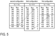
- the bus voltage V BUS is modified from 340 V to 420 V in steps of 10V.
- V BAT V MP - V PP
- the numbers shown in the table of Fig. 5 are merely an illustrative example.
- a closed loop controller with non-linear control behavior may be used to accommodate the three configurations, i.e. to regulate the total output voltage V BAT and to switch between the three configurations.
- the post regulator may be configured to output 0 V (third configuration. In this case the battery voltage V BAT equals the output voltage V MP of the main branch. The respective voltage values are shown in the middle table of Fig. 5 .
- the output voltage of the PP branch is ⁇ 56 V and ⁇ 69 V for an exemplary conversion rate of 0.164.
- the voltage range of the PP branch may be reduced even further (e.g. ⁇ 33 V to ⁇ 47 V for a conversion ratio of 0.097 in the PP branch) if the maximum bus voltage V BUS is increased to 480 V.
- the reconfiguration of the post regulator which is illustrated by the dashed lines in Fig. 5 , is not the only possible option. It should be emphasized that the numbers included in the tables of Fig. 5 are merely provided as an illustrative example. The numbers may be different (even significantly different) in other examples.
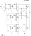
- Fig. 6 illustrates a further embodiment, in which the PP converter 20 includes two (or more) main branches and one PP branch, wherein the outputs of the different branches can be coupled in a configurable manner dependent on the required total output voltage (battery voltage V BAT ).
- the outputs of the two main branches can be connected either in series or in parallel.
- the first main branch with the inverter 21 (commonly used by all branches), the transformer circuit 22, the rectifier circuit 23, and the buffer capacitor C MP is the same as the main branch in Fig. 2 and reference is made to the respective description above.
- the second main branch is composed of the inverter 21, the transformer circuit 52, the rectifier circuit 53, and the buffer capacitor C MP2 .
- Both, the first and the second main branches may be substantially identical.
- the fixed conversion ratio may be the same for the first and the second main branch.
- Also the PP branch including the transformer circuit 42, the rectifier 43 and the post-regulator circuit 44 may be constructed in the same way as in the example of Fig. 2 and reference is made to the respective description above.
- the outputs of the two main branches may be connected either in series or in parallel using the switches S 1 , S 2 , and S 3 .
- the post regulator 44 may be, for example, a DC/DC converter with a controllable conversion ratio or an H-bridge as discussed above with reference to Fig. 4 .
- the switches S 1 , S 2 , and S 3 may be implemented using any type of electronic switches / transistors, such as MOSFETs, IGBTs, bipolar junction transistors, or the like. Suitable driver circuits for switching the transistors on and off are as such known and thus omitted in the figures and not further discussed herein.
- the switches S 1 , S 2 , and S 3 may be implemented using any other type of switches capable of blocking in both direction such as, e.g., (electronic or electromechanical) relays.
- the possibility to connect the two main branches in series allows for a configurable extension of the available voltage range.
- the second main branch may also be deactivated (e.g. by switching off all switches of the synchronous rectifier 25) instead of a parallel connection with the first main branch.
- the concept described in connection with Fig. 6 may also be generalized to more than two main branches.
- Fig. 6 may be used in applications with and without bus voltage adjustment.
- the PP converter 20 of Fig. 6 is used in the power conversion circuit of Fig. 3 with an H-bridge as post regulator 44 (as shown in Fig. 4 ) and bus voltage regulation (as shown in Fig. 5 ).
- the PP converter 20 of Fig. 6 is used in the power conversion circuit of Fig. 3 without bus voltage adjustment (i.e. with a fixed bus voltage V BUS ) but with a post regulator 44 that has a controllable conversion ratio.
- the application (power conversion circuit) depicted in Fig. 3 is merely an example. Although it may be advantageous in many applications that the first converter stage 10 performs a power factor correction, it is understood that this is not necessarily the case. Also the EMI filter 11 may be omitted in the first stage 10 in some applications.
- the first converter stage 10 receives an AC voltage V GRID and the first stage 10 performs an AC/DC conversion to generate the DC bus voltage V BUS .
- the first converter stage 10 may receive a DC input voltage; in this example the first stage 10 has to perform a DC/DC conversion to generate the bus voltage V BUS .
- the first converter stage 10 has to include a (AC/DC or DC/DC) switching converter that allows to adjust/control its output voltage V BUS .
- the controller 50 (see Fig. 3 ) which generates control signals for the switching converters included in the power conversion circuit is not necessarily a single component/device. Rather, the function of the controller may be distributed between several different circuits, which may (or may not) communicate with each other.
- the controller 50 may include a hierarchical structure of control circuits, i.e. several low level control circuits controlled by one or more high level control circuits.
- the controller 50, or parts thereof, may be implemented using a processor which is configured to execute software instructions stored in a memory, wherein the software instructions determine the desired function. Additionally or alternatively, a similar or the same function may be achieved by hard-wired or one-time programmable logic circuitry. In addition to digital/logic circuits, the controller 50 or parts thereof may include analog circuitry.
- the circuit includes a first converter stage configured to provide a DC bus voltage V BUS and a second converter stage configured to receive the DC bus voltage V BUS and to generate an output voltage V BAT therefrom.
- the second converter stage includes at least a main branch and a partial power branch (see, e.g. Figs. 2 and 6 ).
- the main branch is configured to provide, at its output, a first voltage V MP based on the DC bus voltage V BUS and using a fixed conversion ratio.
- the partial power branch is configured to provide, at its output, an adjustable second voltage V R based on the DC bus voltage V BUS .
- the outputs of the main branch and the partial power branch are connected in series to provide the output voltage V BAT .
- the circuit further includes a controller (see Fig. 3 , controller 50) that is capable to set the output voltage.
- the controller controls (the operation of) the first converter stage to adjust the DC bus voltage.
- the controller further controls (the operation of) the partial power branch to adjust the second voltage.
- the main branch may comprise a first DC transformer including an inverter, a resonant transformer circuit and a rectifier (see, e.g. Fig. 2 ), whereas the partial power branch comprises a second DC transformer including the inverter, a further resonant transformer circuit and a further rectifier.
- the partial power branch further comprises an output stage (post-regulator) that is connected to the second DC transformer downstream thereof. The output stage is configured to generate the second voltage from an output voltage of the second DC transformer.
- the output stage / post regulator may include a switching converter (e.g. a buck converter) that allows the adjustment of its output voltage which is provided by the partial power branch as second voltage V R .
- the output stage may include a transistor H-bridge.
- the H-bridge is configured to provide - as second voltage V R and dependent on drive/control signals provided by the controller - one of the following: zero volts, the output voltage V PP of the second DC transformer, or the inverted output voltage -V PP of the second DC transformer.
- the mentioned drive/control signals may be logic signals indicating the configuration of the H-bridge, i.e. indicating which transistors of the H-bridge are on and off.
- the second converter stage includes a second main branch that is configured to provide, at its output, a third voltage V MP2 (see Fig. 6 ) from the DC bus voltage V BUS with the same fixed conversion ratio as the first main branch.
- the second converter stage includes a switching circuit (see Fig. 6 , switches S 1 , S 2 , and S 3 ), which is configured to connect the outputs of the first and second main branches either in series or in parallel.
- the configuration of the switching circuit may also be controlled by the controller. This embodiment may also be operated with a fixed bus voltage V BUS .
- the output stage of the partial power branch may be implemented with transistors that have a lower breakdown voltage as in conventional approaches (e.g. 80 V or 100 V instead of 150 V).
- the method includes generating a DC bus voltage V BUS using a first converter stage and generating, using a second converter stage, an output voltage V BAT from the DC bus voltage V BUS .
- the second converter stage includes at least a main branch and a partial power branch.
- the DC bus voltage V BUS and the second voltage V R are both adjusted to achieve the desired result.
Landscapes
- Engineering & Computer Science (AREA)
- Power Engineering (AREA)
- Dc-Dc Converters (AREA)
- Physics & Mathematics (AREA)
- Electromagnetism (AREA)
Priority Applications (2)
| Application Number | Priority Date | Filing Date | Title |
|---|---|---|---|
| EP22194777.3A EP4336718A1 (de) | 2022-09-09 | 2022-09-09 | Schaltwandler mit teilleistungsverarbeitung |
| US18/235,383 US12597843B2 (en) | 2022-09-09 | 2023-08-18 | Switching converter using partial power processing |
Applications Claiming Priority (1)
| Application Number | Priority Date | Filing Date | Title |
|---|---|---|---|
| EP22194777.3A EP4336718A1 (de) | 2022-09-09 | 2022-09-09 | Schaltwandler mit teilleistungsverarbeitung |
Publications (1)
| Publication Number | Publication Date |
|---|---|
| EP4336718A1 true EP4336718A1 (de) | 2024-03-13 |
Family
ID=83271016
Family Applications (1)
| Application Number | Title | Priority Date | Filing Date |
|---|---|---|---|
| EP22194777.3A Pending EP4336718A1 (de) | 2022-09-09 | 2022-09-09 | Schaltwandler mit teilleistungsverarbeitung |
Country Status (2)
| Country | Link |
|---|---|
| US (1) | US12597843B2 (de) |
| EP (1) | EP4336718A1 (de) |
Citations (4)
| Publication number | Priority date | Publication date | Assignee | Title |
|---|---|---|---|---|
| EP3337023A1 (de) * | 2016-12-16 | 2018-06-20 | Delta Electronics (Shanghai) Co., Ltd. | Stromwandlervorrichtung und stromumwandlungssystem |
| CN109768729A (zh) * | 2019-03-25 | 2019-05-17 | 哈工大(张家口)工业技术研究院 | 单相高频隔离型可变拓扑ac-dc变换器 |
| CN113271029A (zh) * | 2021-05-28 | 2021-08-17 | 青岛大学 | 一种低电压应力宽输出范围dab型单级双向ac/dc变换器 |
| CN114649955A (zh) * | 2022-03-30 | 2022-06-21 | 华中科技大学 | 一种具有输出电压调节能力的直流变换器拓扑结构 |
Family Cites Families (2)
| Publication number | Priority date | Publication date | Assignee | Title |
|---|---|---|---|---|
| TWI474601B (zh) * | 2009-10-08 | 2015-02-21 | Acbel Polytech Inc | High conversion efficiency of the pulse mode resonant power converter |
| DE102012024560B3 (de) * | 2012-12-17 | 2014-03-27 | B2 Electronic Gmbh | Schaltungsanordnung und Verfahren zur Erzeugung einer Prüfspannung und Prüfgerät zur Ermittlung eines Verlustfaktors, welches die Schaltungsanordnung enthält |
-
2022
- 2022-09-09 EP EP22194777.3A patent/EP4336718A1/de active Pending
-
2023
- 2023-08-18 US US18/235,383 patent/US12597843B2/en active Active
Patent Citations (4)
| Publication number | Priority date | Publication date | Assignee | Title |
|---|---|---|---|---|
| EP3337023A1 (de) * | 2016-12-16 | 2018-06-20 | Delta Electronics (Shanghai) Co., Ltd. | Stromwandlervorrichtung und stromumwandlungssystem |
| CN109768729A (zh) * | 2019-03-25 | 2019-05-17 | 哈工大(张家口)工业技术研究院 | 单相高频隔离型可变拓扑ac-dc变换器 |
| CN113271029A (zh) * | 2021-05-28 | 2021-08-17 | 青岛大学 | 一种低电压应力宽输出范围dab型单级双向ac/dc变换器 |
| CN114649955A (zh) * | 2022-03-30 | 2022-06-21 | 华中科技大学 | 一种具有输出电压调节能力的直流变换器拓扑结构 |
Also Published As
| Publication number | Publication date |
|---|---|
| US20250062701A1 (en) | 2025-02-20 |
| US12597843B2 (en) | 2026-04-07 |
Similar Documents
| Publication | Publication Date | Title |
|---|---|---|
| US11563337B2 (en) | High efficiency wireless charging system and method | |
| US10498221B2 (en) | Multi-mode energy router | |
| US8143744B2 (en) | Method and apparatus for providing uninterruptible power | |
| US11424640B2 (en) | Integrated high-voltage-low-voltage DC-DC converter and charger with active filter | |
| RU2721332C2 (ru) | Системная архитектура зарядного устройства для аккумуляторов на базе устройств питания на основе нитрида галлия | |
| US6215286B1 (en) | Step-up/step-down switching regulator operation | |
| EP1175724B1 (de) | Stromwandler | |
| Khan et al. | A highly reliable and high-efficiency quasi single-stage buck–boost inverter | |
| JP4070295B2 (ja) | 高電圧コンバータ回路 | |
| US11223237B2 (en) | High efficiency power converting apparatus and control method | |
| US20090285005A1 (en) | Space-saving inverter with reduced switching losses and increased life | |
| EP2685620B1 (de) | Bidirektionaler gleichspannungswandler und stromquellensystem | |
| US20120086418A1 (en) | Multi-phase switching regulator and driver circuit and control method thereof | |
| US10361624B2 (en) | Multi-cell power converter with improved start-up routine | |
| KR101731477B1 (ko) | Mmc 컨버터의 서브모듈용 전원공급장치 | |
| WO2020248651A1 (zh) | 一种离网裂相器和逆变器系统 | |
| EP3925064B1 (de) | Aufwärtswandler und steuerungsverfahren | |
| EP4336718A1 (de) | Schaltwandler mit teilleistungsverarbeitung | |
| Guler et al. | Model Predictive Control Method With Reduced Switching States for Single-Stage Buck–Boost Rectifier | |
| EP4322382A1 (de) | Resonanzwandler und steuerungsverfahren dafür | |
| WO2021251968A1 (en) | Bidirectional converter adaptive controller | |
| Setiadi et al. | Multilevel Cascaded H-Bridge Linear Amplifier with Unequal DC Capacitor Voltages Using a DC Voltage Source | |
| US11831305B2 (en) | Circuit arrangement for switching switch elements | |
| EP4641907A1 (de) | Flugkondensator-mehrpegelwandler | |
| JP2022184401A (ja) | 電力変換装置 |
Legal Events
| Date | Code | Title | Description |
|---|---|---|---|
| PUAI | Public reference made under article 153(3) epc to a published international application that has entered the european phase |
Free format text: ORIGINAL CODE: 0009012 |
|
| STAA | Information on the status of an ep patent application or granted ep patent |
Free format text: STATUS: THE APPLICATION HAS BEEN PUBLISHED |
|
| AK | Designated contracting states |
Kind code of ref document: A1 Designated state(s): AL AT BE BG CH CY CZ DE DK EE ES FI FR GB GR HR HU IE IS IT LI LT LU LV MC MK MT NL NO PL PT RO RS SE SI SK SM TR |
|
| STAA | Information on the status of an ep patent application or granted ep patent |
Free format text: STATUS: REQUEST FOR EXAMINATION WAS MADE |
|
| 17P | Request for examination filed |
Effective date: 20240617 |
|
| RBV | Designated contracting states (corrected) |
Designated state(s): AL AT BE BG CH CY CZ DE DK EE ES FI FR GB GR HR HU IE IS IT LI LT LU LV MC MK MT NL NO PL PT RO RS SE SI SK SM TR |