EP4336739A1 - Procédé et appareil de communication - Google Patents
Procédé et appareil de communication Download PDFInfo
- Publication number
- EP4336739A1 EP4336739A1 EP22815070.2A EP22815070A EP4336739A1 EP 4336739 A1 EP4336739 A1 EP 4336739A1 EP 22815070 A EP22815070 A EP 22815070A EP 4336739 A1 EP4336739 A1 EP 4336739A1
- Authority
- EP
- European Patent Office
- Prior art keywords
- matrix
- network
- information
- vector quantization
- vector
- Prior art date
- Legal status (The legal status is an assumption and is not a legal conclusion. Google has not performed a legal analysis and makes no representation as to the accuracy of the status listed.)
- Pending
Links
- 238000000034 method Methods 0.000 title claims abstract description 200
- 238000004891 communication Methods 0.000 title claims abstract description 140
- 239000013598 vector Substances 0.000 claims abstract description 1189
- 238000013139 quantization Methods 0.000 claims abstract description 684
- 239000011159 matrix material Substances 0.000 claims description 1061
- 230000006870 function Effects 0.000 claims description 175
- 230000008569 process Effects 0.000 claims description 61
- 230000015654 memory Effects 0.000 claims description 34
- 230000006855 networking Effects 0.000 claims description 34
- 238000013507 mapping Methods 0.000 claims description 26
- 238000003860 storage Methods 0.000 claims description 18
- 238000004590 computer program Methods 0.000 claims description 7
- 230000011664 signaling Effects 0.000 abstract description 54
- 238000012545 processing Methods 0.000 description 81
- 230000006835 compression Effects 0.000 description 68
- 238000007906 compression Methods 0.000 description 68
- 238000007781 pre-processing Methods 0.000 description 65
- 230000000737 periodic effect Effects 0.000 description 54
- 238000012549 training Methods 0.000 description 43
- 238000013528 artificial neural network Methods 0.000 description 33
- 238000010606 normalization Methods 0.000 description 29
- 238000005516 engineering process Methods 0.000 description 26
- 238000005259 measurement Methods 0.000 description 24
- 238000005284 basis set Methods 0.000 description 23
- 230000004913 activation Effects 0.000 description 13
- 230000005540 biological transmission Effects 0.000 description 13
- 238000010586 diagram Methods 0.000 description 13
- 238000011156 evaluation Methods 0.000 description 12
- 239000013256 coordination polymer Substances 0.000 description 11
- 238000005457 optimization Methods 0.000 description 10
- 230000006399 behavior Effects 0.000 description 9
- 230000008859 change Effects 0.000 description 9
- 238000006243 chemical reaction Methods 0.000 description 8
- 238000013461 design Methods 0.000 description 8
- 230000008570 general process Effects 0.000 description 8
- 230000009467 reduction Effects 0.000 description 8
- 101100481876 Danio rerio pbk gene Proteins 0.000 description 7
- 101100481878 Mus musculus Pbk gene Proteins 0.000 description 7
- 230000004069 differentiation Effects 0.000 description 6
- 230000000694 effects Effects 0.000 description 6
- 230000004927 fusion Effects 0.000 description 6
- 238000013473 artificial intelligence Methods 0.000 description 5
- 238000013527 convolutional neural network Methods 0.000 description 5
- 230000007246 mechanism Effects 0.000 description 4
- 230000008901 benefit Effects 0.000 description 3
- 101150047356 dec-1 gene Proteins 0.000 description 3
- 238000002360 preparation method Methods 0.000 description 3
- 230000017105 transposition Effects 0.000 description 3
- 230000009471 action Effects 0.000 description 2
- 230000006978 adaptation Effects 0.000 description 2
- 230000003190 augmentative effect Effects 0.000 description 2
- 238000004364 calculation method Methods 0.000 description 2
- 230000001413 cellular effect Effects 0.000 description 2
- 125000004122 cyclic group Chemical group 0.000 description 2
- 238000000354 decomposition reaction Methods 0.000 description 2
- 238000009826 distribution Methods 0.000 description 2
- 230000008713 feedback mechanism Effects 0.000 description 2
- 230000000977 initiatory effect Effects 0.000 description 2
- 230000007774 longterm Effects 0.000 description 2
- 238000010801 machine learning Methods 0.000 description 2
- 238000012423 maintenance Methods 0.000 description 2
- 238000007726 management method Methods 0.000 description 2
- 230000010287 polarization Effects 0.000 description 2
- 230000000306 recurrent effect Effects 0.000 description 2
- 238000005070 sampling Methods 0.000 description 2
- 230000003595 spectral effect Effects 0.000 description 2
- 230000007704 transition Effects 0.000 description 2
- 102100022734 Acyl carrier protein, mitochondrial Human genes 0.000 description 1
- 101000678845 Homo sapiens Acyl carrier protein, mitochondrial Proteins 0.000 description 1
- 101100065246 Mus musculus Enc1 gene Proteins 0.000 description 1
- 238000003491 array Methods 0.000 description 1
- 210000004556 brain Anatomy 0.000 description 1
- 238000013500 data storage Methods 0.000 description 1
- 230000009849 deactivation Effects 0.000 description 1
- 238000013135 deep learning Methods 0.000 description 1
- 230000001934 delay Effects 0.000 description 1
- 238000009795 derivation Methods 0.000 description 1
- 230000009977 dual effect Effects 0.000 description 1
- 238000000605 extraction Methods 0.000 description 1
- 238000011049 filling Methods 0.000 description 1
- 230000006872 improvement Effects 0.000 description 1
- 238000011068 loading method Methods 0.000 description 1
- 238000010295 mobile communication Methods 0.000 description 1
- 230000007727 signaling mechanism Effects 0.000 description 1
- 230000001131 transforming effect Effects 0.000 description 1
- 230000001960 triggered effect Effects 0.000 description 1
- XLYOFNOQVPJJNP-UHFFFAOYSA-N water Substances O XLYOFNOQVPJJNP-UHFFFAOYSA-N 0.000 description 1
Images





Classifications
-
- H—ELECTRICITY
- H04—ELECTRIC COMMUNICATION TECHNIQUE
- H04B—TRANSMISSION
- H04B7/00—Radio transmission systems, i.e. using radiation field
- H04B7/02—Diversity systems; Multi-antenna system, i.e. transmission or reception using multiple antennas
- H04B7/04—Diversity systems; Multi-antenna system, i.e. transmission or reception using multiple antennas using two or more spaced independent antennas
- H04B7/06—Diversity systems; Multi-antenna system, i.e. transmission or reception using multiple antennas using two or more spaced independent antennas at the transmitting station
- H04B7/0613—Diversity systems; Multi-antenna system, i.e. transmission or reception using multiple antennas using two or more spaced independent antennas at the transmitting station using simultaneous transmission
- H04B7/0615—Diversity systems; Multi-antenna system, i.e. transmission or reception using multiple antennas using two or more spaced independent antennas at the transmitting station using simultaneous transmission of weighted versions of same signal
- H04B7/0619—Diversity systems; Multi-antenna system, i.e. transmission or reception using multiple antennas using two or more spaced independent antennas at the transmitting station using simultaneous transmission of weighted versions of same signal using feedback from receiving side
- H04B7/0621—Feedback content
- H04B7/0626—Channel coefficients, e.g. channel state information [CSI]
-
- H—ELECTRICITY
- H04—ELECTRIC COMMUNICATION TECHNIQUE
- H04B—TRANSMISSION
- H04B7/00—Radio transmission systems, i.e. using radiation field
- H04B7/02—Diversity systems; Multi-antenna system, i.e. transmission or reception using multiple antennas
- H04B7/04—Diversity systems; Multi-antenna system, i.e. transmission or reception using multiple antennas using two or more spaced independent antennas
- H04B7/0413—MIMO systems
- H04B7/0452—Multi-user MIMO systems
-
- H—ELECTRICITY
- H04—ELECTRIC COMMUNICATION TECHNIQUE
- H04B—TRANSMISSION
- H04B7/00—Radio transmission systems, i.e. using radiation field
- H04B7/02—Diversity systems; Multi-antenna system, i.e. transmission or reception using multiple antennas
- H04B7/04—Diversity systems; Multi-antenna system, i.e. transmission or reception using multiple antennas using two or more spaced independent antennas
- H04B7/0413—MIMO systems
- H04B7/0456—Selection of precoding matrices or codebooks, e.g. using matrices antenna weighting
-
- H—ELECTRICITY
- H04—ELECTRIC COMMUNICATION TECHNIQUE
- H04B—TRANSMISSION
- H04B7/00—Radio transmission systems, i.e. using radiation field
- H04B7/02—Diversity systems; Multi-antenna system, i.e. transmission or reception using multiple antennas
- H04B7/04—Diversity systems; Multi-antenna system, i.e. transmission or reception using multiple antennas using two or more spaced independent antennas
- H04B7/06—Diversity systems; Multi-antenna system, i.e. transmission or reception using multiple antennas using two or more spaced independent antennas at the transmitting station
- H04B7/0613—Diversity systems; Multi-antenna system, i.e. transmission or reception using multiple antennas using two or more spaced independent antennas at the transmitting station using simultaneous transmission
- H04B7/0615—Diversity systems; Multi-antenna system, i.e. transmission or reception using multiple antennas using two or more spaced independent antennas at the transmitting station using simultaneous transmission of weighted versions of same signal
- H04B7/0619—Diversity systems; Multi-antenna system, i.e. transmission or reception using multiple antennas using two or more spaced independent antennas at the transmitting station using simultaneous transmission of weighted versions of same signal using feedback from receiving side
- H04B7/0658—Feedback reduction
- H04B7/0663—Feedback reduction using vector or matrix manipulations
Definitions
- This application relates to the field of communication technologies, and in particular, to a communication method and apparatus.
- a 5th generation (5th generation, 5G) mobile communication system has higher requirements on a system capacity, spectral efficiency, and the like.
- application of a massive multiple-input multiple-output (massive multiple-input multiple-output, massive-MIMO) technology plays an important role in improving spectral efficiency of the system.
- massive-MIMO technology By using the massive-MIMO technology, a base station can provide high-quality services for more user equipments (user equipment, UE) at the same time.
- a key step is that the base station precodes downlink data of a plurality of UEs.
- the base station may obtain channel state information (channel state information, CSI) of a downlink channel, to perform precoding based on the CSI. How to enable the base station to effectively obtain the CSI of the downlink channel is a technical problem worth studying.
- Embodiments of this application provide a communication method and apparatus, to improve CSI feedback efficiency.
- a communication method may be performed on a terminal device side.
- the method may be performed by using software, hardware, or a combination of software and hardware.
- the method is performed by a terminal device, or performed by a circuit system, or performed by a larger device including a terminal device.
- the circuit system can implement functions of the terminal device.
- the method includes: determining channel state information, where the channel state information is determined based on S indexes of S vectors, each of the S vectors is included in a first vector quantization dictionary, the first vector quantization dictionary includes N 1 vectors, and N 1 and S are both positive integers; and sending the channel state information to a network device.
- the channel state information may be determined based on the first vector quantization dictionary.
- the channel information obtained by the terminal device through measurement is represented by using indexes of one or more vectors included in the first vector quantization dictionary, to obtain the channel state information.
- quantizing channel information by using the first vector quantization dictionary is equivalent to performing dimension expansion on channel information or maintenance at a relatively high dimension as much as possible, thereby improving quantization precision. Therefore, in this method, high-precision feedback can be implemented by using relatively low signaling overheads.
- each of the N 1 vectors represents one channel feature. Because each of the N 1 vectors can represent one channel feature, corresponding channel information may be quantized based on the first vector quantization dictionary to obtain channel state information, thereby reducing feedback overheads and relatively ensuring quantization precision.
- the S vectors are determined based on S pieces of first channel information and the first vector quantization dictionary, and the S pieces of first channel information are information output by an encoder network. It may be understood that the S pieces of first channel information output by the encoder network indicate a status of a downlink channel, and the S pieces of first channel information may be quantized based on the first vector quantization dictionary. Feedback overheads can be reduced through such quantization.
- a quantization network and a compression network are jointly designed (for example, an encoder network and a vector quantization dictionary can be obtained through jointly training), so that joint optimization can be implemented between compression and quantization, to reduce a performance loss and improve overall accuracy of fed-back channel state information.
- the encoder network and a decoder network cooperate, so that an original channel matrix can be compressed.
- the original channel matrix may be compressed as a whole by using the network. In this case, discarded information can be reduced, thereby reducing a compression loss.
- the quantization network and the compression network are jointly designed, so that joint optimization can be implemented between compression and quantization, to reduce a performance loss and improve overall accuracy of fed-back channel state information.
- the N 1 vectors have a same length.
- the length is equal to at least one dimension in an output dimension of the encoder network.
- the lengths of the N 1 vectors are equal to at least one dimension in the output dimension of the encoder network, so that the N 1 vectors can be easily used to quantize the channel information output by the encoder network.
- an input dimension of the encoder network is determined based on an input dimension of a first reference encoder network
- the output dimension of the encoder network is determined based on an output dimension of the first reference encoder network.
- one or more reference network groups may be defined in a protocol, or information about one or more reference network groups may be received from the network device.
- Each reference network group may include a reference encoder network and a corresponding reference decoder network.
- the reference encoder network and the corresponding reference decoder network may be obtained through joint training. Two communication parties may separately perform, based on a reference network, offline training on an encoder network and a decoder network that may be used in actual application.
- the encoder network currently used by the terminal device is obtained through training based on the first reference encoder network included in a first reference network (or based on the first reference encoder network and a first reference decoder network included in a first reference network). Therefore, the input dimension of the encoder network may be determined based on the input dimension of the first reference encoder network, and the output dimension of the encoder network may be determined based on the output dimension of the first reference encoder network. For example, the input dimension of the encoder network is equal to the input dimension of the first reference encoder network, and the output dimension of the encoder network is equal to the output dimension of the first reference encoder network.
- the encoder network used by the terminal device can meet a performance requirement, and the encoder network used by the terminal device can also meet a current network condition, to improve adaptability of the encoder network to an actual network environment.
- the first reference encoder network corresponds to the first reference decoder network. For example, if the first reference encoder network belongs to the first reference network, and the first reference network includes the first reference encoder network and the first reference decoder network, the first reference encoder network corresponds to the first reference decoder network. For example, the first reference encoder network and the first reference decoder network may be obtained through joint training.
- the first reference network includes the first reference encoder network and the first reference decoder network.
- a reference network may include a reference encoder network and a corresponding reference decoder network.
- the reference encoder network and the reference decoder network included in the reference network may be obtained through joint training.
- the first reference network further includes a vector quantization dictionary (which may also be referred to as a reference vector quantization dictionary).
- the reference encoder network, the reference decoder network, and the vector quantization dictionary may be jointly trained and optimized. Therefore, in addition to the first reference encoder network and the first reference decoder network, the first reference network may further include the reference vector quantization dictionary. In this manner, joint optimization between compression and quantization can be better implemented.
- the first vector quantization dictionary is the reference vector quantization dictionary, or the first vector quantization dictionary may be different from the reference vector quantization dictionary.
- the first vector quantization dictionary used by the UE is the reference vector quantization dictionary. In a process of communication between the UE and the network device, the vector quantization dictionary used by the UE may be updated, and the first vector quantization dictionary is, for example, an updated vector quantization dictionary.
- the input dimension of the encoder network is M or M ⁇ 2
- the output dimension of the encoder network is D ⁇ S
- M and D are both positive integers
- M ⁇ N tx ⁇ N sb ⁇ z, S ⁇ M, z is a positive integer greater than or equal to 1
- N tx represents a quantity of transmit antenna ports of the network device
- N sb represents a quantity of frequency domain sub-bands.
- N tx and N sb are both positive integers.
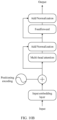
- the terminal device may preprocess the downlink channel matrix and then input a preprocessed downlink channel matrix to the encoder network. For example, in a process of preprocessing the downlink channel matrix, the terminal device may obtain an eigen subspace matrix based on the downlink channel matrix, and then perform space-frequency joint projection on the eigen subspace matrix to obtain a complex matrix. After obtaining the complex matrix, the terminal device may further perform dimension reduction processing on the complex matrix, and input a processed complex matrix to the encoder network; or convert a processed complex matrix into a real matrix and then input the real matrix to the encoder network. In this case, the input dimension of the encoder network may be M or M ⁇ 2.
- a dimension of the downlink channel matrix is N tx ⁇ N rx ⁇ N RB , and M ⁇ N tx ⁇ N sb ⁇ z. It can be understood that information compression is completed in this manner. To be specific, in this step, main feature elements can be selected to approximately express original information. In this processing manner, a matrix dimension can be further reduced, to reduce complexity of subsequent processing (such as processing of the encoder network). The matrix dimension obtained in this preprocessing manner is used as an input dimension of a subsequent neural network (for example, the input dimension of the encoder network), and further affects a dimension for reconstructing the downlink channel matrix on the network device side.
- the input dimension of the encoder network is M ⁇ N ⁇ 2 or M ⁇ N
- the output dimension of the encoder network is D ⁇ P ⁇ Q
- S P ⁇ Q
- M, N, D, P, and Q are all positive integers
- N tx represents a quantity of transmit antenna ports of the network device
- N sb represents a quantity of frequency domain sub-bands
- N rx represents a quantity of receive antenna ports of the terminal device
- x and y are both greater than 1; or x is equal to 1 and y is greater than 1; or x is greater than 1 and y is equal to 1.
- N rx , N tx , and N sb are both positive integers.
- the terminal device may obtain an eigen subspace matrix based on the downlink channel matrix, and then perform space-frequency joint projection on the eigen subspace matrix to obtain a complex matrix.
- the terminal device may further perform dimension reduction processing on the complex matrix, and input a processed complex matrix to the encoder network; or convert a processed complex matrix into a real matrix and then input the real matrix to the encoder network.
- the input dimension of the encoder network may be M ⁇ N ⁇ 2 or M x N.
- the terminal device does not need to further perform dimension reduction processing; but may input the complex matrix to the encoder network, or convert the complex matrix into a real matrix and then input the real matrix to the encoder network.
- the input dimension of the encoder network may also be M ⁇ N ⁇ 2 or M ⁇ N.
- the terminal device may first perform dimension reduction processing on the downlink channel matrix, and then perform space-frequency joint projection on a matrix obtained through dimension reduction to obtain a complex matrix.
- the input dimension of the encoder network may also be M ⁇ N ⁇ 2 or M ⁇ N.
- the terminal device reduces a process of performing an SVD operation on the downlink channel matrix, to simplify the implementation.
- the input dimension of the encoder network is M ⁇ N ⁇ T ⁇ 2 or M ⁇ N ⁇ T
- the output dimension of the encoder network is D ⁇ P ⁇ Q ⁇ R
- S P ⁇ Q ⁇ R
- M, N, D, P, Q, R, and T are all positive integers
- T N rx
- S S ⁇ N rx ⁇ N tx ⁇ N sb
- N tx represents a quantity of transmit antenna ports of the network device
- N sb represents a quantity of frequency domain sub-bands
- N rx represents a quantity of receive antenna ports of the terminal device.
- N rx , N tx , and N sb are both positive integers.
- the terminal device may first convert the downlink channel matrix, to obtain a two-dimensional matrix included in a matrix obtained through conversion. Subsequently, space-frequency joint projection may be performed on the two-dimensional matrix to obtain a complex matrix.
- the input dimension of the encoder network may be M ⁇ N ⁇ T ⁇ 2 or M ⁇ N ⁇ T.
- the terminal device reduces a process of performing an SVD operation on the downlink channel matrix, to simplify the implementation.
- the method further includes: sending information about the first vector quantization dictionary to the network device.
- the terminal device may send the first vector quantization dictionary to the network device before sending the channel state information to the network device or when sending the channel state information (for example, in a same time unit), so that the network device can obtain the downlink channel matrix through reconstruction based on the first vector quantization dictionary and the channel state information from the terminal device.
- the vector quantization dictionary may be updated online.
- the terminal device may update the vector quantization dictionary, so that the used vector quantization dictionary can better match a constantly changing channel environment, to more accurately feed back CSI.
- the sending information about the first vector quantization dictionary to the network device includes: periodically sending the information about the first vector quantization dictionary to the network device; periodically sending the information about the first vector quantization dictionary to the network device after first configuration information is received from the network device; sending the information about the first vector quantization dictionary to the network device after first configuration information is received from the network device; sending the information about the first vector quantization dictionary to the network device in an arrival time unit of a first delay after first configuration information is received from the network device; sending the information about the first vector quantization dictionary to the network device after first parameter information is received from the network device, where the first parameter information indicates parameter information of the decoder network; sending the information about the first vector quantization dictionary to the network device in an arrival time unit of a first delay after first parameter information is received from the network device, where the first parameter information indicates parameter information of the decoder network; sending the information about the first vector quantization dictionary to the network device after first indication information is received from the network device, where the first indication information is used to indicate (or trigger) sending of a
- a report parameter of the vector quantization dictionary may be configured in the first configuration information. If the terminal device sends the information about the first vector quantization dictionary to the network device, there may be a plurality of sending manners. Some of the manners are listed herein. A specific manner in which the terminal device sends the first vector quantization dictionary may be negotiated by the terminal device and the network device, or may be configured by the network device, or may be specified in a protocol, or the like. This is relatively flexible.
- the first configuration information includes information about the first delay, or information about the first delay is indicated by using other signaling from the network device, or the first delay is agreed on in a protocol.
- the method further includes: determining that a current networking manner is a first networking manner, and determining the first vector quantization dictionary corresponding to the first networking manner; determining that a current moving speed belongs to a first interval, and determining the first vector quantization dictionary corresponding to the first interval; determining a handover from a second cell to a first cell, and determining the first vector quantization dictionary corresponding to the first cell; determining switching from a second reference encoder network to the first reference encoder network, and determining the first vector quantization dictionary corresponding to the first reference encoder network; or receiving second indication information from the network device, where the second indication information indicates the first vector quantization dictionary.
- the current networking manner is the first networking manner
- the first vector quantization dictionary is a vector quantization dictionary corresponding to the first networking manner
- the moving speed of the terminal device belongs to the first interval
- the first vector quantization dictionary is a vector quantization dictionary corresponding to the first interval
- the terminal device is handed over from the second cell to the first cell
- the first vector quantization dictionary is a vector quantization dictionary corresponding to the first cell
- a used reference encoder network is switched from the second reference encoder network to the first reference encoder network
- the first vector quantization dictionary is a vector quantization dictionary corresponding to the first reference encoder network
- the first vector quantization dictionary is a vector quantization dictionary indicated by the second indication information, and the second indication information comes from the network device.
- a manner of determining the first vector quantization dictionary by the terminal device includes, for example, an explicit manner and/or an implicit manner. If the explicit manner is used, for example, the network device may send signaling to indicate the first vector quantization dictionary. If the implicit manner is used, the foregoing several manners may be included. In other words, a correspondence may be established between the vector quantization dictionary and corresponding information (for example, a networking manner and a moving speed of the terminal device), so that the terminal device can determine the first vector quantization dictionary based on the information. A signaling indication of the network device may be not required in the implicit manner, to reduce signaling overheads. Alternatively, the terminal device may determine the first vector quantization dictionary in a manner of combining the explicit manner and the implicit manner. This is not limited in this embodiment of this application.
- the method further includes: sending second parameter information to the network device, where the second parameter information indicates a parameter of the encoder network.
- the terminal device may send information about the parameter of the encoder network to the network device.
- the vector quantization dictionary may be alternatively updated by the network device. It is more appropriate that the network device has a decision-making right.
- the terminal device may send the parameter information of the encoder network to the network device, so that the network device can update the vector quantization dictionary with reference to the parameter information of the encoder network.
- the sending second parameter information to the network device includes: periodically sending the second parameter information to the network device; periodically sending the second parameter information to the network device after second configuration information is received from the network device; sending the second parameter information to the network device after second configuration information is received from the network device; sending the second parameter information to the network device in an arrival time unit of a second delay after second configuration information is received from the network device; sending the second parameter information to the network device after third indication information is received from the network device, where the third indication information is used to indicate (for example, trigger) sending of the parameter information of the encoder network; or sending the second parameter information to the network device in an arrival time unit of a second delay after third indication information is received from the network device, where the third indication information indicates sending of the parameter information of the encoder network.
- a report parameter of the second parameter information may be configured in the second configuration information. If the terminal device sends the second parameter information to the network device, there may be a plurality of sending manners. Some of the manners are listed herein. A specific manner in which the terminal device sends the second parameter information may be negotiated by the terminal device and the network device, or may be configured by the network device, may be specified in a protocol, or the like. This is relatively flexible.
- the second configuration information includes information about the second delay, or information about the second delay is indicated by using other signaling from the network device, or the second delay is agreed on in a protocol.
- another communication method is provided.
- the method may be performed on a network device side.
- the method may be performed by using software, hardware, or a combination of software and hardware.
- the method is performed by a network device, or performed by a larger device including a network device, or performed by a circuit system, or performed by an AI module for assisting a network device or a network element for assisting a network device.
- the circuit system can implement functions of the network device, and the AI module and the network element are independent of the network device.
- the network device is an access network device such as a base station.
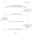
- the method includes: receiving channel state information, where the channel state information includes S indexes of S vectors; and obtaining information about a reconstructed downlink channel matrix based on the S indexes and a first vector quantization dictionary, where each of the S vectors is included in the first vector quantization dictionary, the first vector quantization dictionary includes N 1 vectors, and N 1 and S are both positive integers.
- each of the N 1 vectors represents one channel feature.
- the obtaining information about a reconstructed downlink channel matrix based on the S indexes and a first vector quantization dictionary includes: obtaining the information about the reconstructed downlink channel matrix based on the first vector quantization dictionary, the S indexes, and a decoder network.
- the obtaining information about a reconstructed downlink channel matrix based on the S indexes and a first vector quantization dictionary includes: performing inverse mapping on the S indexes based on the first vector quantization dictionary to obtain a first matrix; and obtaining the information about the reconstructed downlink channel matrix based on the first matrix and the decoder network.
- the obtaining the information about the reconstructed downlink channel matrix based on the first matrix and the decoder network includes: inputting the first matrix to the decoder network to obtain a second matrix; and obtaining the information about the reconstructed downlink channel matrix based on the second matrix.
- M represents a space domain basis vector set
- U 1 , k represents a k th vector in the space domain basis vector set
- N represents a frequency domain basis vector set
- U 2,l represents an l th vector in the frequency domain basis vector set
- a length of a vector included in the frequency domain basis vector set is N sb
- N tx represents a quantity of transmit antenna ports of the network device
- N sb represents a quantity of frequency domain sub-bands
- U 2 , l * represents a conjugate transpose matrix (or vector) of U 2 ,l
- D, S, M, and N are all positive integers.
- ..s represents the S indexes of the S vectors in the first vector quantization dictionary
- a function q(x) indicates to map, based on the first vector quantization dictionary, the S indexes to a first matrix whose dimension is D ⁇ S
- a function ⁇ dec ( x ) indicates to reconstruct the first matrix by using the decoder network to obtain a second matrix whose dimension is M ⁇ 2
- the first matrix and the second matrix are both real matrices
- M represents a space domain basis vector set
- U 1,( j , k ) represents a j th vector in the space domain basis vector set
- M represents a frequency domain basis vector set
- U 2,( j , l ) represents aj th vector in the frequency domain basis vector set
- a length of a vector included in the frequency domain basis vector set is N sb
- N tx represents a quantity of transmit antenna ports of the network device
- N sb represents a quantity of frequency domain sub-bands
- U 2 , j l * represents a conjugate transpose vector of U 2 , ( j , l )
- D, S , and M are all positive integers.
- t 1...
- t 1...
- M represents a space domain basis vector set
- U 1,k represents a k th vector in the space domain basis vector set
- a length of a vector included in the space domain basis vector set is N tx
- U 2,l represents an l th vector in the frequency domain basis vector set
- a length of a vector included in the frequency domain basis vector set is N sb
- N tx represents a quantity of transmit antenna ports of the network device
- N sb represents a quantity of frequency domain sub-bands
- U 2 , l * represents a conjugate transpose vector of U 2 ,l
- D, S, M, and N are all positive integers.
- M represents a space domain basis vector set
- U 2,( j , l ) represents a j th vector in the frequency domain basis vector set
- a length of a vector included in the frequency domain basis vector set is N sb
- N tx represents a quantity of transmit antenna ports of the network device
- N sb represents a quantity of frequency domain sub-bands
- U 2 , j l * represents a conjugate transpose vector of U 2 , ( j,l )
- D, S, and M are all positive integers.
- t 1 ...T indicates to process (or reconstruct), based on the second matrix and the relationship (that is, the foregoing formula), T matrices
- N represents a frequency domain basis vector set
- U 2,l represents an l th vector in the frequency domain basis vector set
- a length of a vector included in the frequency domain basis vector set is N sb
- N tx represents a quantity of transmit antenna ports of the network device
- N sb represents a quantity of frequency domain sub-bands
- U 2 , l * represents a conjugate transpose vector of U 2 ,l
- D, S, M, N, and T are all positive integers.
- t 1...
- the method further includes: receiving information about the first vector quantization dictionary.
- the receiving information about the first vector quantization dictionary includes: periodically receiving the information about the first vector quantization dictionary; periodically receiving the information about the first vector quantization dictionary after first configuration information is sent; receiving the information about the first vector quantization dictionary after first configuration information is sent; receiving the information about the first vector quantization dictionary in an arrival time unit of a first delay after first configuration information is sent; receiving the information about the first vector quantization dictionary after first parameter information is sent, where the first parameter information indicates parameter information of a decoder network; receiving the information about the first vector quantization dictionary in an arrival time unit of a first delay after first parameter information is sent, where the first parameter information indicates parameter information of a decoder network; receiving the information about the first vector quantization dictionary after first indication information is sent, where the first indication information is used to indicate (for example, trigger) sending of the vector quantization dictionary; or receiving the information about the first vector quantization dictionary in an arrival time unit of a first delay after first indication information is sent, where the first indication information is used to indicate (for example, trigger) to send the vector quant
- the first configuration information includes information about the first delay, or information about the first delay is indicated by using other signaling from the network device, or the first delay is agreed on in a protocol.
- the method further includes: determining that a current networking manner with a terminal device is a first networking manner, and determining the first vector quantization dictionary corresponding to the first networking manner; determining that a current moving speed of a terminal device belongs to a first interval, and determining the first vector quantization dictionary corresponding to the first interval; determining that a terminal device is handed over from a second cell to a first cell, and determining the first vector quantization dictionary corresponding to the first cell; determining that a terminal device is switched from a second reference encoder network to a first reference encoder network, and determining the first vector quantization dictionary corresponding to the first reference encoder network; or sending second indication information, where the second indication information indicates the information about the first vector quantization dictionary.
- the current networking manner is the first networking manner
- the first vector quantization dictionary is a vector quantization dictionary corresponding to the first networking manner
- the moving speed of the terminal device belongs to the first interval
- the first vector quantization dictionary is a vector quantization dictionary corresponding to the first interval
- the terminal device is handed over from the second cell to the first cell
- the first vector quantization dictionary is a vector quantization dictionary corresponding to the first cell
- a reference encoder network used by the terminal device is switched from the second reference encoder network to a first reference encoder network
- the first vector quantization dictionary is a vector quantization dictionary corresponding to the first reference encoder network
- the method includes: sending second indication information, where the second indication information indicates the information about the first vector quantization dictionary.
- the method further includes: receiving second parameter information, where the second parameter information indicates a parameter of an encoder network.
- the receiving second parameter information includes: periodically receiving the second parameter information; periodically receiving the second parameter information after second configuration information is sent; receiving the second parameter information after second configuration information is sent; receiving the second parameter information in an arrival time unit of a second delay after second configuration information is sent; receiving the second parameter information after third indication information is sent, where the third indication information indicates sending of parameter information of the encoder network; or receiving the second parameter information in an arrival time unit of a second delay after third indication information is sent, where the third indication information indicates sending of parameter information of the encoder network.
- the second configuration information includes information about the second delay, or information about the second delay is indicated by using other signaling from the network device, or the second delay is agreed on in a protocol.
- a communication apparatus may implement the method in the first aspect.
- the communication apparatus has functions of the foregoing terminal device.
- the apparatus may include modules that are in a one-to-one correspondence with the methods/operations/steps/actions described in the first aspect.
- the modules may be implemented by a hardware circuit, software, or a combination of a hardware circuit and software.
- the communication apparatus includes a baseband apparatus and a radio apparatus.
- the communication apparatus includes a processing unit (also referred to as a processing module sometimes) and a transceiver unit (also referred to as a transceiver module sometimes).
- the transceiver unit can implement a sending function and a receiving function.
- the transceiver unit When the transceiver unit implements the sending function, the transceiver unit may be referred to as a sending unit (sometimes referred to as a sending module). When the transceiver unit implements the receiving function, the transceiver unit may be referred to as a receiving unit (sometimes referred to as a receiving module). The sending unit and the receiving unit may be a same functional module. The functional module is referred to as a transceiver unit. The functional module can implement the sending function and the receiving function. Alternatively, the sending unit and the receiving unit may be different functional modules. The transceiver unit is a general term of these functional modules.
- the processing unit is configured to: determine channel state information, where the channel state information is determined based on S indexes of S vectors, each of the S vectors is included in a first vector quantization dictionary, the first vector quantization dictionary includes N 1 vectors, and N 1 and S are both positive integers.
- the transceiver unit (or the sending unit) is configured to send the channel state information to a network device.
- the communication apparatus includes a processor and a communication interface.
- the processor uses the communication interface to implement the method described in the first aspect.
- the communication interface is used by the apparatus to communicate with another device.
- the communication interface may be a transceiver, a circuit, a bus, a pin, a module, or another type of communication interface.
- the processor is configured to: determine channel state information, where the channel state information is determined based on S indexes of S vectors, each of the S vectors is included in a first vector quantization dictionary, the first vector quantization dictionary includes N 1 vectors, and N 1 and S are both positive integers; and the processor sends the channel state information to a network device by using the communication interface.
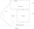
- the apparatus may further include a memory.
- the memory is configured to store program instructions and data.
- the memory is coupled to the processor. When executing the instructions stored in the memory, the processor can implement the method described in the first aspect.
- the communication apparatus includes a processor, coupled to a memory and configured to execute instructions in the memory, to implement the method in the first aspect.
- the communication apparatus further includes another component, for example, an antenna, an input/output module, and an interface.
- these components may be hardware, software, or a combination of software and hardware.
- a communication apparatus may implement the method in the second aspect.
- the communication apparatus has functions of the foregoing network device.
- the network device is, for example, a base station or a baseband apparatus in a base station.
- the apparatus may include modules that are in a one-to-one correspondence with the methods/operations/steps/actions described in the second aspect.
- the modules may be implemented by a hardware circuit, software, or a combination of a hardware circuit and software.
- the communication apparatus includes a baseband apparatus and a radio apparatus.
- the communication apparatus includes a processing unit (also referred to as a processing module sometimes) and a transceiver unit (also referred to as a transceiver module sometimes).
- a processing unit also referred to as a processing module sometimes
- a transceiver unit also referred to as a transceiver module sometimes.
- the transceiver unit (or the receiving unit) is configured to receive channel state information.
- the channel state information includes S indexes of S vectors.
- the processing unit is configured to obtain information about a reconstructed downlink channel matrix based on the S indexes and a first vector quantization dictionary.
- Each of the S vectors is included in the first vector quantization dictionary.
- the first vector quantization dictionary includes N 1 vectors. N 1 and S are both positive integers.
- the communication apparatus includes a processor and a communication interface.
- the processor uses the communication interface to implement the method described in the second aspect.
- the communication interface is used by the apparatus to communicate with another device.
- the communication interface may be a transceiver, a circuit, a bus, a pin, a module, or another type of communication interface.
- the processor receives the channel state information by using the communication interface.
- the channel state information includes S indexes of S vectors.
- the processor is configured to obtain information about a reconstructed downlink channel matrix based on the S indexes and a first vector quantization dictionary. Each of the S vectors is included in the first vector quantization dictionary.
- the first vector quantization dictionary includes N 1 vectors. N 1 and S are both positive integers.
- the apparatus may further include a memory.
- the memory is configured to store program instructions and data.
- the memory is coupled to the processor. When executing the instructions stored in the memory, the processor can implement the method described in the second aspect.
- the communication apparatus includes a processor, coupled to a memory and configured to execute instructions in the memory, to implement the method in the second aspect.
- the communication apparatus further includes another component, for example, an antenna, an input/output module, and an interface.
- these components may be hardware, software, or a combination of software and hardware.
- a computer-readable storage medium configured to store a computer program or instructions. When the computer program or instructions is/are run, the method in the first aspect or the second aspect is implemented.
- a computer program product including instructions is provided.
- the method in the first aspect or the second aspect is implemented.
- a chip system includes a processor, and may further include a memory.
- the chip system is configured to implement the method in the first aspect or the second aspect.
- the chip system may include a chip, or may include a chip and another discrete device.
- a communication system including the communication apparatus in the third aspect and the communication apparatus in the fourth aspect.
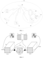
- the communication system 10 includes one or more communication apparatuses 30 (for example, a terminal device).
- the one or more communication apparatuses 30 are connected to one or more core network (core network, CN) devices through one or more access network (radio access network, RAN) devices 20, to implement communication between a plurality of communication devices.
- core network core network
- RAN radio access network
- the communication system 10 is a communication system that supports a 4G (including long term evolution (long term evolution, LTE)) access technology, a communication system that supports a 5G (sometimes referred to as new radio, NR) access technology, a wireless fidelity (wireless fidelity, Wi-Fi) system, a cellular system related to the 3rd generation partnership project (3rd generation partnership project, 3GPP), a communication system that supports convergence of a plurality of radio technologies, or a future-oriented evolved system.
- 4G including long term evolution (long term evolution, LTE)
- 5G sometimes referred to as new radio, NR
- NR new radio
- wireless fidelity wireless fidelity
- 3GPP 3rd generation partnership project
- 3GPP 3rd generation partnership project
- the terminal device is, briefly referred to as a terminal, a device having wireless sending and receiving functions.
- the terminal device may be mobile or fixed.
- the terminal device may be deployed on land, for example, including an indoor or outdoor device, a handheld device, or a vehicle-mounted device; may be deployed on water (for example, on a ship); or may be deployed in the air (for example, on an airplane, a balloon, and a satellite).
- the terminal device may include a mobile phone (mobile phone), a tablet computer (pad), a computer with wireless sending and receiving functions, a virtual reality (virtual reality, VR) terminal device, an augmented reality (augmented reality, AR) terminal device, a wireless terminal device in industrial control (industrial control), a wireless terminal device in self-driving (self-driving), a wireless terminal device in remote medical (remote medical), a wireless terminal device in a smart grid (smart grid), a wireless terminal device in transportation safety (transportation safety), a wireless terminal device in a smart city (smart city), and/or a wireless terminal device in a smart home (smart home).
- the terminal device may be a cellular phone, a cordless phone, a session initiation protocol (session initiation protocol, SIP) phone, a wireless local loop (wireless local loop, WLL) station, a personal digital assistant (personal digital assistant, PDA), a handheld device or a computing device with a wireless communication function, a vehicle-mounted device, a wearable device, a terminal device in the future 5th generation (the 5th generation, 5G) network, a terminal device in a future evolved public land mobile network (public land mobile network, PLMN), or the like.
- the terminal device may also be referred to as user equipment (user equipment, UE) sometimes.
- the terminal device may communicate with a plurality of access network devices that use different technologies.
- the terminal device may communicate with an access network device that supports LTE, or may communicate with an access network device that supports 5G, or may simultaneously communicate with an access network device that supports LTE and an access network device that supports 5G. This is not limited in embodiments of this application.
- an apparatus configured to implement functions of the terminal device may be a terminal device, or may be an apparatus that can support the terminal device in implementing the functions, for example, a chip system, a hardware circuit, a software module, or a hardware circuit and a software module.
- the apparatus may be installed in the terminal device or may be used in a matching manner with the terminal device.
- the chip system may include a chip, or may include a chip and another discrete device.
- the RAN may include one or more RAN devices, for example, a RAN device 20.
- An interface between the RAN device and the terminal device may be a Uu interface (or referred to as an air interface).
- Uu interface or referred to as an air interface.
- names of these interfaces may remain unchanged, or may be replaced with other names. This is not limited in this application.
- the RAN device is a node or a device that enables the terminal device to access the radio network.
- the RAN device may also be referred to as a network device or a base station.
- the RAN device includes but is not limited to: a base station, a next-generation NodeB (generation NodeB, gNB) in 5G, an evolved NodeB (evolved NodeB, eNB), a radio network controller (radio network controller, RNC), a NodeB (NodeB, NB), a base station controller (base station controller, BSC), a base transceiver station (base transceiver station, BTS), a home base station (for example, a home evolved NodeB or a home NodeB, HNB), a baseband unit (baseband unit, BBU), a transmitting and receiving point (transmitting and receiving point, TRP), a transmission point (transmitting point, TP), and/or a mobile switching center.
- generation NodeB generation Node
- the access network device may be at least one of a central unit (central unit, CU), a distributed unit (distributed unit, DU), a central unit control plane (CU control plane, CU-CP) node, a central unit user plane (CU user plane, CU-UP) node, integrated access and backhaul (integrated access and backhaul, IAB), a radio controller in a cloud radio access network (cloud radio access network, CRAN) scenario, or the like.
- a central unit central unit
- DU distributed unit
- CU control plane CU control plane, CU-CP
- CU user plane central unit user plane
- CU-UP integrated access and backhaul
- IAB integrated access and backhaul
- the access network device may be a relay station, an access point, a vehicle-mounted device, a terminal device, a wearable device, an access network device in a 5G network, an access network device in a future evolved public land mobile network (public land mobile network, PLMN), or the like.
- PLMN public land mobile network
- an apparatus configured to implement functions of the access network device may be an access network device, or may be an apparatus that can support the access network device in implementing the functions, for example, a chip system, a hardware circuit, a software module, or a hardware circuit and a software module.
- the apparatus may be installed in the access network device or may be used in a matching manner with the access network device.
- an example in which the apparatus for implementing the functions of the access network device is an access network device and the access network device is a base station is used to describe the technical solutions provided in embodiments of this application.
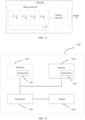
- the protocol layer structure may include a control plane protocol layer structure and a user plane protocol layer structure.
- the control plane protocol layer structure may include functions of protocol layers such as a radio resource control (radio resource control, RRC) layer, a packet data convergence protocol (packet data convergence protocol, PDCP) layer, a radio link control (radio link control, RLC) layer, a media access control (media access control, MAC) layer, and a physical layer.
- the user plane protocol layer structure may include functions of protocol layers such as the PDCP layer, the RLC layer, the MAC layer, and the physical layer.
- a service data adaptation protocol (service data adaptation protocol, SDAP) layer may be further included above the PDCP layer.
- a RAN device may include a CU and a DU.
- a plurality of DUs may be centrally controlled by one CU.
- an interface between the CU and the DU may be referred to as an F1 interface.
- a control plane (control plane, CP) interface may be F1-C
- a user plane (user panel, UP) interface may be F1-U.
- the CU and the DU may be obtained through division based on protocol layers of a wireless network. For example, functions of the PDCP layer and a protocol layer above the PDCP layer are set on the CU, and functions of a protocol layer below the PDCP layer (for example, the RLC layer and the MAC layer) are set on the DU. For another example, functions of a protocol layer above the PDCP layer are set on the CU, and functions of the PDCP layer and a protocol layer below the PDCP layer are set on the DU.
- division of processing functions of the CU and the DU based on the protocol layers is merely an example. Division may be alternatively performed in another manner. For example, the CU or the DU may have functions of more protocol layers through division. For another example, the CU or the DU may alternatively have some processing functions of protocol layers through division. In a design, some functions of the RLC layer and functions of protocol layers above the RLC layer are set on the CU, and remaining functions of the RLC layer and functions of a protocol layer below the RLC layer are set on the DU. In another design, division of functions of the CU or the DU may be alternatively performed based on a service type or another system requirement. For example, division may be performed based on delays.
- a function whose processing time needs to meet a delay requirement is set on the DU, and a function whose processing time does not need to meet the delay requirement is set on the CU.
- the CU may alternatively have one or more functions of a core network.
- the CU may be disposed on a network side to facilitate centralized management.
- a radio unit (radio unit, RU) of the DU is remotely disposed.
- the RU has a radio frequency function.
- the DU and the RU may be further divided at the physical layer (physical layer, PHY).
- the DU may implement higher-layer functions of the PHY layer
- the RU may implement lower-layer functions of the PHY layer.
- the functions of the PHY layer may include: a cyclic redundancy check (cyclic redundancy check, CRC) code addition function, channel encoding, rate matching, scrambling, modulation, layer mapping, precoding, resource mapping, physical antenna mapping, and/or a radio frequency sending function.
- a cyclic redundancy check cyclic redundancy check, CRC
- the functions of the PHY layer may include CRC, channel decoding, rate dematching, descrambling, demodulation, layer demapping, channel sounding, resource demapping, physical antenna demapping, and/or a radio frequency receiving function.
- the higher-layer functions of the PHY layer may include some functions of the PHY layer. For example, the functions are closer to the MAC layer.
- the lower-layer functions of the PHY layer may include some other functions of the PHY layer. For example, these functions are closer to a radio frequency function.
- the higher-layer functions of the PHY layer may include CRC code addition, channel encoding, rate matching, scrambling, modulation, and layer mapping; and the lower-layer functions of the PHY layer may include precoding, resource mapping, physical antenna mapping, and a radio frequency sending function.
- the higher-layer functions of the PHY layer may include CRC code addition, channel encoding, rate matching, scrambling, modulation, layer mapping, and precoding; and the lower-layer functions of the PHY layer may include resource mapping, physical antenna mapping, and a radio frequency sending function.
- the functions of the CU may be implemented by one entity or different entities.
- the functions of the CU may be further divided.
- the control plane and the user plane are separated and implemented by using different entities that are respectively a control plane CU entity (namely, a CU-CP entity) and a user plane CU entity (namely, a CU-UP entity).
- the CU-CP entity and the CU-UP entity may be coupled to the DU, to jointly complete functions of the RAN device.
- signaling generated by the CU may be sent to the terminal device through the DU, or signaling generated by the terminal device may be sent to the CU through the DU.
- signaling at the RRC layer or the PDCP layer may be finally processed to obtain signaling at the physical layer and sent to the terminal device, or be converted from signaling received from the physical layer.
- the signaling at the RRC layer or the PDCP layer may be considered to be sent through the DU or sent through the DU and the RU.
- any one of the DU, the CU, the CU-CP, the CU-UP, and the RU may be a software module, a hardware structure, or a software module and a hardware structure.
- the DU, the CU, the CU-CP, and the CU-UP are software modules
- the RU is a hardware structure.
- the RAN device includes the CU-CP, the CU-UP, the DU, and the RU.
- an execution entity of the method in embodiments of this application includes the DU, or includes the DU and the RU, or includes the CU-CP, the DU, and the RU. This is not limited. Methods performed by the modules also fall within the protection scope of embodiments of this application.
- the network device in embodiments of this application is mainly an access network device, unless otherwise specified, the "network device” described below may be an "access network device”.
- the communication system may further include more terminal devices and more RAN devices; and may further include another device, for example, may include a core network device and/or a node configured to implement an artificial intelligence function.
- the network architecture shown in FIG. 1 may be used in communication systems of various radio access technologies (radio access technology, RAT), for example, a 4G communication system, or a 5G (or referred to as a new radio (new radio, NR)) communication system, or a transition system between an LTE communication system and a 5G communication system.
- the transition system may also be referred to as a 4.5G communication system, or may be a future communication system, for example, a 6G communication system.
- the network architecture and the service scenarios described in embodiments of this application are intended to describe the technical solutions in embodiments of this application more clearly, and do not constitute a limitation on the technical solutions provided in embodiments of this application.
- a person of ordinary skill in the art may know that, with evolution of a communication network architecture and emergence of new service scenarios, the technical solutions provided in embodiments of this application are also applicable to similar technical problems.
- the method provided in this application may also be used for communication between other communication devices, for example, communication between a macro base station and a micro base station in a wireless backhaul link, or communication between a first terminal device and a second terminal device in a sidelink (sidelink, SL). This is not limited.
- the communication between the network device and the terminal device is used as an example for description.
- the network device may perform precoding based on CSI fed back by the terminal device.
- the network device may process a to-be-sent signal by using a precoding matrix matching a channel condition.
- This technology can be used to match a precoded to-be-sent signal with a channel, to improve quality (for example, an SINR) of a signal received by the terminal device and reduce complexity of eliminating impact between channels by the terminal device.
- a sending device for example, a network device
- a plurality of receiving devices for example, terminal devices
- the sending device may alternatively perform precoding in another manner.
- precoding is performed by using a preset precoding matrix or through weighting.
- specific content of the precoding is not described in this specification.
- Dual-domain compression may include compression in two dimensions: space domain compression and frequency domain compression.
- Dual-domain compression may include two steps: space-frequency joint projection and compression.
- Space-frequency joint projection indicates to project a space-frequency two-dimensional channel matrix H separately by using a U1 matrix and a U2 matrix.
- the U1 matrix represents a space domain basis
- the U2 matrix represents a frequency domain basis.
- a projected equivalent coefficient matrix H ⁇ has a sparse feature. Only some elements in the matrix H ⁇ have relatively large modulus values. In other words, energy is concentrated in few space-frequency positions. Some coefficients with relatively high energy are selected from the sparse equivalent matrix H ⁇ .
- the coefficients are quantized to implement compression. In other words, through the dual-domain compression, low-dimensional subspace is used to represent high-dimensional channel space.
- the CSI feedback may also be referred to as a CSI report (CSI report).
- the CSI feedback is that, in a wireless communication system, a receiving end (for example, a terminal device) reports, to a transmitting end (for example, a network device), information used to describe a channel attribute of a communication link.
- the CSI report includes, for example, a precoding matrix indicator (precoding matrix indicator, PMI), a rank indicator (rank indicator, RI), and a channel quality indicator (channel quality indicator, CQI).
- precoding matrix indicator precoding matrix indicator, PMI
- rank indicator rank indicator
- CQI channel quality indicator
- the foregoing enumerated content included in the CSI is merely an example for description, and should not constitute any limitation on embodiments of this application.
- the CSI may include one or more of the foregoing items, or may include other information used to represent CSI other than the foregoing enumerated information. This is not limited in embodiments of this application.
- Neural network neural network, NN
- the neural network is a specific implementation form of machine learning technologies. According to the universal approximation theorem, theoretically, the neural network can approximate any continuous function, so that the neural network can learn any mapping. In a conventional communication system, rich expert knowledge is required to design a communication module. However, a neural network-based deep learning communication system can automatically find an implicit pattern structure from a large quantity of data sets, establish a mapping relationship between data, and obtain performance better than that of a conventional modeling method.
- a deep neural network is a neural network with a relatively large quantity of layers.
- the DNN may include a multi-layer perceptron (multi-layer perceptron, MLP), a convolutional neural network (convolutional neural network, CNN), a recurrent neural network (recurrent neural network, RNN), and the like.
- MLP multi-layer perceptron
- CNN convolutional neural network
- RNN recurrent neural network
- a specific form of the DNN is not limited in embodiments of this application.
- Vector quantization auto-encoder vector-quantization auto-encoder, VQ-AE
- VQ-AE vector-quantization auto-encoder
- the VQ-AE network may include an encoder and a corresponding decoder.
- the encoder and/or the decoder are/is implemented by using a neural network (such as a DNN).
- the encoder may also be referred to as an encoder network
- the decoder may also be referred to as a decoder network.
- AE auto-encoder
- VQ vector quantization
- the encoder and the corresponding decoder may be obtained through joint training; and in the VQ-AE network, the encoder, the corresponding decoder, and a corresponding VQ dictionary may be obtained through joint training.
- the encoder, the decoder, and the VQ dictionary that are obtained through training may be used to encode and decode information.
- an image is encoded by using the VQ-AE.
- an output eigenmatrix is, for example, Z e ( x ).
- the original image is input information of the encoder
- Z e ( x ) is output information of the encoder or an encoding result.
- a feature distance is calculated between each D- dimensional vector in the eigenmatrix Z e ( x ) and each of x preset D -dimensional vectors.
- the x preset D -dimensional vectors may be considered as a vector quantization dictionary, or a vector quantization dictionary includes the x D -dimensional vectors and optionally includes another vector.
- the vector quantization dictionary is also obtained through training.
- e 1 to e x represent the x preset D -dimensional vectors.
- an index i of the i th D -dimensional vector in the x D- dimensional vectors is filled in a two-dimensional grid Q ( z
- the index matrix Z q (x) may be sent to a decoder side.
- an index i of the i th D-dimensional vector in the x D -dimensional vectors is filled in a two-dimensional grid Q ( z
- the index matrix Z q ( x ) may be sent to a decoder side.
- determining the i th D -dimensional vector from the x D- dimensional vectors is not limited in this application.
- the decoder side may process the index matrix Z q (x). For example, an index in the index matrix Z q (x) is restored to a corresponding matrix based on the vector quantization dictionary.
- the matrix is represented as p(x
- the decoder may reconstruct information about the original image based on the information.
- a quantity of nouns indicates "a singular noun or a plural noun", namely, "one or more".
- At least one means one or more
- a plurality of means two or more.
- “And/or” describes an association relationship for describing associated objects and indicates that three relationships may exist.
- a and/or B may indicate the following cases: Only A exists, both A and B exist, and only B exists, where A and B may be singular or plural.
- the character “/" may indicate an "or” relationship between associated objects.
- A/B indicates A or B.
- the symbol “/” may further indicate a division operation.
- the symbol “ ⁇ ” may also be replaced with a symbol "*”.
- ordinal numerals such as “first” and “second” in embodiments of this application are used to distinguish between a plurality of objects, and are not intended to limit sizes, content, an order, a time sequence, application scenarios, priorities, or importance degrees of the plurality of objects.
- a first vector quantization dictionary and a second vector quantization dictionary may be a same vector quantization dictionary, or may be different vector quantization dictionaries.
- these names do not indicate that the two vector quantization dictionaries include different content, priorities, application scenarios, importance degrees, or the like.
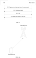
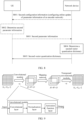
- a CSI feedback mechanism uses a procedure shown in FIG. 3 .
- a base station sends signaling, and correspondingly, UE receives the signaling from the base station.
- the signaling is used to configure channel measurement information.
- the signaling is used to notify the UE of at least one of the following: time information for performing channel measurement, a type of a reference signal (reference signal, RS) for performing channel measurement, a time domain resource of a reference signal, a frequency domain resource of a reference signal, and a report condition of a measured quantity.
- RS reference signal
- the base station sends a reference signal to the UE, and correspondingly, the UE receives the reference signal from the base station.
- the UE measures the reference signal to obtain CSI.
- the UE sends the CSI to the base station, and correspondingly, the base station receives the CSI from the UE.
- the base station sends data to the UE based on the CSI, and correspondingly, the UE receives the data from the base station.
- the data sent by the base station to the UE is carried on a downlink channel, for example, carried on a physical downlink shared channel (physical downlink shared channel, PDSCH).
- a CSI feedback technology may be used by the base station to send another downlink channel to the UE, for example, a physical downlink control channel (physical downlink control channel, PDCCH).
- PDCCH physical downlink control channel
- the base station may determine, based on an RI fed back by the UE, a quantity of flows used when the data is sent to the UE; and may determine, based on a CQI fed back by the UE, a modulation order used when the data is sent to the UE, and/or an encoding bit rate of a channel carrying the data, and the like.
- the base station may determine, based on a PMI fed back by the UE, a precoding matrix used when the data is sent to the UE, and the like.
- the UE may perform compression (such as dual-domain compression) on a measured channel matrix by using a sparse representation of a channel, and then quantize a coefficient extracted through compression to obtain the CSI.
- compression such as dual-domain compression
- some coefficients with higher energy need to be selected from an equivalent sparse matrix H ⁇ , and the coefficients are quantized and fed back. Remaining coefficients are not fed back. Therefore, when the CSI feedback technology is used to feed back the CSI, a part of measured information is directly discarded. This may lead to low accuracy of the fed-back CSI.
- channel state information is determined based on a first vector quantization dictionary.
- the channel state information may be represented by using indexes of one or more vectors included in the first vector quantization dictionary. Because a dimension of a vector is usually relatively large, it is equivalent to dimension expansion on information or reduction of an information loss as much as possible, thereby improving quantization precision.
- the fed-back information is an index of a vector, it may be considered that an original channel matrix is compressed, thereby reducing signaling overheads.
- a quantization network and a compression network are jointly designed, so that joint optimization can be implemented between compression and quantization, to reduce a performance loss and improve overall accuracy of the fed-back channel state information.
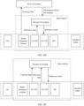
- FIG. 4A shows an architecture of a communication network in a communication system 10 according to an embodiment of this application. Any one of embodiments shown in FIG. 5 to FIG. 8 that are subsequently provided is applicable to the architecture.
- a network device included in FIG. 4A is, for example, an access network device 20 included in the communication system 10, and a terminal device included in FIG. 4A is, for example, a communication apparatus 30 included in the communication system 10. The network device can communicate with the terminal device.
- a machine learning technology in embodiments of this application is a specific implementation of an artificial intelligence (artificial intelligence, AI) technology.
- AI artificial intelligence
- AI is a technology for performing complex computing through simulating human brains. With improvement of data storage and capabilities, AI is increasingly applied.
- FIG. 4B is a schematic diagram of a first application framework of AI in a communication system.
- a data source data source
- a model training node model training host
- a model inference node uses the AI model to perform inference based on the inference data provided by the data source and obtain an inference result.
- the inference result is uniformly planned by an execution entity (actor), and is sent to one or more execution objects (for example, network entities) for execution.
- the AI model includes a decoder network in a VQ-AE network.
- the decoder network is deployed on a network device side.
- An inference result of the decoder network is, for example, used for reconstruction of a downlink channel matrix.
- the AI model includes an encoder network in the VQ-AE network.
- the encoder network is deployed on a UE side.
- An inference result of the encoder network is, for example, used for encoding of a downlink channel matrix.
- FIG. 4C , FIG. 4D, or FIG. 4E is a schematic diagram of a second application framework of AI in a communication system.
- a first AI module independent of a base station receives the training data.
- the first AI module analyzes or trains the training data to obtain an AI model.
- the first AI module may perform inference by using a corresponding AI model and the inference data to obtain the parameter.
- the first AI module may send information about the AI model to a second AI module located in a base station (or located in a RAN in description), and the second AI module performs inference by using a corresponding AI model and the inference data to obtain the parameter.
- the first AI module may send information about the AI model to a second AI module located in a base station (or located in a RAN in description), and the second AI module performs inference by using a corresponding AI model and the inference data to obtain the parameter.
- the AI model used by the second AI module for inference may be obtained by the second AI module through receiving the training data and training the training data.
- the AI model includes the decoder network in the VQ-AE network.
- an inference result of the decoder network is, for example, used for reconstruction of a downlink channel matrix.
- the AI model includes the encoder network in the VQ-AE network, and model information of the encoder network may be sent to the UE for inference performed by the UE.
- the AI model may be briefly referred to as a model, and the AI model may be considered as mapping from an input parameter (for example, an input matrix) to an output parameter (for example, an output matrix).
- the input matrix may be a matrix determined based on the received CSI.
- the training data may include a known input matrix, or include a known input matrix and a corresponding output matrix. The training data is used to train the AI model.
- the training data may be data from the base station, a CU, a CU-CP, a CU-UP, a DU, an RU, UE, and/or another entity; and/or data inferred by using the AI technology.
- the inference data includes an input matrix, and is used to infer an output matrix by using a model.
- the inference data may be data from the base station, the CU, the CU-CP, the CU-UP, the DU, the RU, the UE, and/or the another entity.
- the inferred matrix may be considered as policy information, and sent to the execution object.
- the inferred matrix may be sent to the base station, the CU, the CU-CP, the CU-UP, the DU, the RU, the UE, or the like for further processing, for example, for reconstruction of a downlink channel matrix.
- the decoder network in the VQ-AE network may be deployed in the network device (for example, the base station), for example, deployed in the RU, the DU, or the second AI module; or may be deployed in an AI device (for example, the first AI module) independent of the network device.
- the inference result of the decoder network may be obtained by the network device through inference, or may be sent to the network device after the first AI module performs inference.
- an example in which the decoder network is deployed in the network device is used for description.
- the encoder network in the VQ-AE network is deployed in the UE, and the UE may perform inference by using the encoder network.
- a relatively typical neural network architecture is a dual architecture.
- An auto-encoder is used as an example, compressed transmission can be implemented through joint optimization of an encoder and a decoder.
- one or more reference network groups may be obtained through training. These reference networks each may be a pair of an encoder network (or referred to as reference encoder networks) and a decoder network (or referred to as reference decoder networks).
- a reference network group may include a reference encoder network and a corresponding reference decoder network.
- These reference networks may be trained offline or online. If the training is performed offline, it may be specified in a protocol.
- the protocol may provide parameters such as network structures and/or weights of these reference networks (including the reference encoder network and the reference decoder network).
- the UE or the network device may implement these reference networks according to the protocol.
- evaluated performance corresponding to these specific reference networks may be provided based on an agreed-on data set.
- encoding is performed on a UE side.
- the UE may select a reference decoder network in the one or more reference network groups based on a factor such as complexity or performance, and train (offline or online), in a targeted manner, one or more encoder networks that can be used in actual application.
- the encoder network trained by the UE in the targeted manner may be referred to as an encoder network corresponding to the reference decoder network.
- the network device may also select a reference encoder network in the one or more reference network groups, and train (offline or online), in a targeted manner, one or more decoder networks that can be used in actual application.
- the decoder network trained by the network device in the targeted manner may be referred to as a decoder network corresponding to the reference encoder network.
- the protocol may not restrict whether the actually used encoder network or decoder network is a reference network predefined in the protocol, but may restrict evaluated performance of the actually used encoder network and corresponding reference decoder network to meet indicators specified in the protocol, and may further restrict evaluated performance of the actually used decoder network and corresponding reference encoder network to meet indicators specified in the protocol.
- the protocol may restrict the actually deployed encoder network to have same input and output dimensions as the corresponding reference encoder network, and/or restrict the decoder network to have same input and output dimensions as the corresponding reference decoder network.
- An embodiment of this application is based on a VQ-AE network.
- a difference from the auto-encoder lies in that a reference network group (or a reference network) in the VQ-AE network may be a pair of a vector quantization encoder network (that may also be briefly referred to as a reference encoder network) and a vector quantization decoder network (that may also be briefly referred to as a reference decoder network), and a corresponding vector quantization dictionary (set).
- the vector quantization dictionary (set) may also be referred to as a reference vector quantization dictionary (set).
- the vector quantization encoder network, the vector quantization decoder network, and the vector quantization dictionary (set) may be jointly trained and optimized. Similar to the foregoing steps, one or more reference network groups may be trained offline or online. If the offline training method is used, the protocol may define the one or more reference network groups, and optionally define a performance evaluation method and an indicator of the reference network.
- a vector quantization dictionary A defined in a reference network group is not necessarily a universal set of a vector quantization dictionary B defined in the protocol.
- the protocol may define the vector quantization dictionary B including more vectors, and the vector quantization dictionary A corresponding to the group of the reference encoder network/the reference decoder network may be only a subset of the vector quantization dictionary B.
- the "define" herein may be an association relationship.
- the protocol defines a reference vector quantization dictionary set.
- the set includes a plurality of vector quantization dictionaries.
- the reference vector quantization dictionary A included in the reference network group is, for example, one reference vector quantization dictionary in the reference vector quantization dictionary set.
- each reference vector quantization dictionary corresponds to an index.
- the reference vector quantization dictionary included in the reference network group may correspond to an index in the reference vector quantization dictionary set.
- step S501 in an embodiment of this application starts, it may be assumed that two communication parties respectively train an encoder network and a decoder network for actual application (for example, meeting a performance indicator) online or offline based on the one or more reference network groups specified in the protocol.
- the vector quantization dictionary needs to be known by the two communication parties, at an initial stage of network access communication, the vector quantization dictionary used by the two communication parties is, for example, predefined in the corresponding reference network; or may be determined in another manner.
- one communication party may exchange, with the other communication party, the vector quantization dictionary trained offline by the communication party, and actually use the vector quantization dictionary.
- FIG. 5 is a flowchart of a first communication method according to an embodiment of this application.
- a network device sends configuration information to UE, and correspondingly, the UE receives the configuration information from the network device.
- the configuration information is referred to as configuration information 1 or third configuration information.
- the third configuration information may be used to configure a parameter used during CSI measurement and/or CSI reporting. Therefore, the configuration information may also be referred to as configuration information of CSI measurement.
- the third configuration information may be sent by the network device to the UE.
- the third configuration information may indicate CSI resource configuration (CSI resource settings) and/or CSI reporting configuration (report quantity), and the like.
- the third configuration information may be used to indicate at least one of the following: a type of a reference signal used for measurement (for example, a channel state information reference signal (channel state information reference signal, CSI-RS) or a signal in a synchronization signal and a physical broadcast channel block (synchronization signal and physical broadcast channel block, SSB), a time domain resource and/or a frequency domain resource of a reference signal (for example, an index of the reference signal, a port number of the reference signal, and/or a period of the reference signal), a CSI reporting format, a time domain resource and/or a frequency domain resource used for CSI reporting, a trigger condition of CSI reporting, and/or a period of CSI reporting.
- a type of a reference signal used for measurement for example, a channel state information reference signal (channel state
- the UE determines CSI by using a vector quantization dictionary in a VQ-AE network.
- the vector quantization dictionary in the VQ-AE network is similar to a public key or a public codebook, and needs to be known by both communication parties (for example, the network device and the UE) in advance. Therefore, the third configuration information may also include information about the vector quantization dictionary.
- the following uses examples to describe a definition manner of the vector quantization dictionary.
- a protocol predefines the vector quantization dictionary.
- the vector quantization dictionary may be predefined by the protocol.
- the protocol may define one or more vector quantization dictionaries, and may define a format, a specific parameter, and the like of each vector quantization dictionary.
- the two communication parties may obtain all information about the vector quantization dictionary according to the protocol.
- the information includes a specific value (or may be referred to as a weight, namely, a weight of a vector quantization dictionary that includes values of some or all elements in the vector quantization dictionary) of each vector included in the vector quantization dictionary.
- Each vector quantization dictionary includes one or more vectors.
- the weight of the vector quantization dictionary may be jointly updated with an encoder network/a decoder network. Therefore, in an offline training scenario, the weight of the vector quantization dictionary may also be determined in an offline training manner.
- offline training usually focuses on generalization performance of a model. Therefore, it may be considered that a vector quantization dictionary obtained through offline training is generally applicable to all users in a given communication scenario.
- the vector quantization dictionary with universality obtained through offline training is pre-loaded by the device and used as the first vector quantization dictionary used when the UE initially accesses the network, until the UE is notified that the vector quantization dictionary needs to be switched or updated.
- the predefined vector quantization dictionary with universality and a pair of a reference encoder network and a reference decoder network may form a default reference network group.
- the default reference network group may further include another parameter. This is not limited.
- the default reference network group may be a reference network used by the UE when the UE initially accesses the network, when the UE enters a fallback mode, and/or when the network device does not indicate the UE by using signaling.
- a protocol predefines a format of the vector quantization dictionary.
- the protocol may define one or more vector quantization dictionaries, and may define a format of each vector quantization dictionary, for example, define a length of a vector and/or a quantity of vectors included in the vector quantization dictionary.
- a weight of a vector may not be defined, or some elements of a vector may be defined, or weights of some vectors in the dictionary may be defined.
- An undefined weight of a vector can be filled or updated through another mechanism.
- VQ-AE-CSI solution When a solution of feeding back CSI by using a VQ-AE network (for example, briefly referred to as a VQ-AE-CSI solution) is actually applied, for some UEs in relatively fixed positions in a cell, the UEs may not require generalization of the network. Therefore, parameter filling or update may be performed on the vector quantization dictionary based on a real-time channel environment.
- the method may be described as follows: determining, in some online training manners, a dictionary weight that is adapted to a channel environment of a small region in which these UEs are located. In this manner, CSI reconstruction precision can be further improved.
- the online training (or referred to as online update) manner is described in another embodiment below.
- the network device sends the vector quantization dictionary.
- the network device may send a format and/or a specific parameter (for example, a weight parameter) of one or more vector quantization dictionaries to the UE, and the UE uses the vector quantization dictionary from the network device as the vector quantization dictionary in the VQ-AE-CSI solution. If the network device sends a plurality of vector quantization dictionaries to the UE, the network device may further additionally indicate a specific to-be-used vector quantization dictionary to the UE, or the UE may determine a specific to-be-used vector quantization dictionary based on another factor (for example, an application scenario). This case may be for a scenario in which a plurality of small cells are deployed. Each small cell may have only limited coverage.
- a specific parameter for example, a weight parameter
- the small cell obtains a targeted vector quantization dictionary through offline training or online training.
- the vector quantization dictionary may be used by the UE accessing the small cell.
- the network device may determine a format, a weight parameter, and the like of the possible vector quantization dictionary, and deliver the vector quantization dictionary to the UE.
- the protocol may predefine the plurality of vector quantization dictionaries.
- the UE may determine the vector quantization dictionary in an implicit manner, or in an explicit manner, or in a combination of an implicit manner and an explicit manner.
- the following uses examples for description.
- the explicit manner includes: The UE determines the to-be-used vector quantization dictionary based on signaling (for example, indication signaling or switching signaling) sent by the network device.
- signaling for example, indication signaling or switching signaling
- the signaling sent by the network device to the UE is, for example, radio resource control (radio resource control, RRC) signaling, a media access control (media access control, MAC) control element (control element, CE), or downlink control information (downlink control information, DCI).
- RRC radio resource control
- MAC media access control
- CE control element
- DCI downlink control information
- the signaling includes, for example, the third configuration information or other signaling.
- the third configuration information further includes a format and/or a weight parameter of the first vector quantization dictionary (corresponding to the foregoing manner in which the network device sends the vector quantization dictionary), or further includes an index (corresponding to the foregoing manner in which the protocol predefines the vector quantization dictionary, for example, the third configuration information indicates an index of the first vector quantization dictionary from the plurality of vector quantization dictionaries predefined by the protocol).
- the first vector quantization dictionary is, for example, a dictionary used by the VQ-AE network.
- the network device may send the first vector quantization dictionary or the index of the first vector quantization dictionary to the UE by using the third configuration information. This is a relatively simple dictionary delivery manner. In a scenario in which real-time update is not required, the first vector quantization dictionary may be delivered by using the third configuration information (usually, RRC signaling).
- the signaling may indicate the index or an index set of the first vector quantization dictionary. In this design, signaling overheads can be reduced.
- the network device may send one piece of signaling or may send a plurality of pieces of signaling to the UE.
- a notification manner for the plurality of pieces of signaling may be a combination of the foregoing several signaling notification manners.
- the network device sends an index set of a group of vector quantization dictionaries by using signaling 1 (for example, RRC signaling or a MAC-CE), and the network device further indicates the index of the first vector quantization dictionary by using DCI, where the first vector quantization dictionary is included in the group of vector quantization dictionaries; and the UE may determine the first vector quantization dictionary based on the two pieces of signaling. Formats, specific parameters, and/or the like of the group of vector quantization dictionaries may be included in the third configuration information.
- signaling 1 for example, RRC signaling or a MAC-CE
- information such as the formats and the parameters of the group of vector quantization dictionaries is sent by using the third configuration information, and then the signaling 1 and the DCI are used to indicate the specific to-be-used vector quantization dictionary.
- formats, specific parameters, and/or indexes of various vector quantization dictionaries in the group of vector quantization dictionaries may be alternatively specified in a protocol.
- the network device sends a group of vector quantization dictionaries (including formats, weights, and/or indexes of each group of vector quantization dictionaries) by using RRC signaling, and indicates an index of a vector quantization dictionary in the group of vector quantization dictionaries by using a MAC-CE or DCI; and the UE may determine the vector quantization dictionary based on the two pieces of signaling.
- a group of vector quantization dictionaries including formats, weights, and/or indexes of each group of vector quantization dictionaries
- a vector quantization dictionary (for example, the first vector quantization dictionary) may be predefined.
- the first vector quantization dictionary is universal to all channels of the UE. In this case, switching of the vector quantization dictionary is not related.
- the network device may not need to send the first vector quantization dictionary, and the UE may determine the first vector quantization dictionary according to the protocol; and the network device may also determine the first vector quantization dictionary according to the protocol.
- the first vector quantization dictionary may be defined together with a (default) reference network.
- the reference network may include a reference vector quantization dictionary, a decoder network, and an encoder network.
- the protocol may define the plurality of vector quantization dictionaries.
- these vector quantization dictionaries have a correspondence with configuration of one or more other system parameters. Therefore, when the one or more system parameters change, the vector quantization dictionaries corresponding to the system parameters are also switched accordingly.
- the following uses examples for description.
- a networking scenario (or referred to as a networking manner) and each of the plurality of vector quantization dictionaries.
- Different networking manners may match different vector quantization dictionaries, or may match a same vector quantization dictionary.
- the UE may determine a vector quantization dictionary (for example, the first vector quantization dictionary) corresponding to the first networking manner. Therefore, the network device may not need to send the first vector quantization dictionary.
- the network device may also determine the first vector quantization dictionary according to the protocol.
- different networking manners include a line-of-sight (line of sight, LoS) path and a non-line-of-sight (non line of sight, nLoS) path, and the two networking manners may respectively correspond to vector quantization dictionaries.
- different networking manners include an urban microcell (urban microcell, Umi) and an urban macrocell (urban macrocell, Uma), and Umi and Uma may correspond to respective vector quantization dictionaries.
- the vector quantization dictionary is bound to the networking manner. Therefore, switching of the vector quantization dictionary is in the implicit manner. To be specific, when a communication scenario (or a networking manner) is determined, the vector quantization dictionary is also determined. On the contrary, when a communication scenario is switched, the vector quantization dictionary may also be switched accordingly.
- the plurality of vector quantization dictionaries may match different moving speeds.
- a moving speed of the UE is divided into a plurality of intervals, and different intervals respectively match corresponding vector quantization dictionaries.
- a division granularity is not limited in this embodiment of this application. Different intervals may match different vector quantization dictionaries, or may match a same vector quantization dictionary.
- the UE may determine a vector quantization dictionary (for example, the first vector quantization dictionary) corresponding to the first interval. Therefore, the network device may not need to send the first vector quantization dictionary.
- the vector quantization dictionary is bound to the moving speed of the UE.
- the vector quantization dictionary is also determined.
- the vector quantization dictionary may also be switched accordingly.
- the plurality of vector quantization dictionaries may match different antenna configuration and/or bandwidths.
- the bandwidth herein is, for example, a bandwidth of a carrier used for communication between the two communication parties, or a maximum bandwidth supported by the UE, or a bandwidth of an active bandwidth part (bandwidth part, BWP) of the UE. This is not limited.
- BWP bandwidth part
- the vector quantization dictionary may be related to the encoder network and/or the decoder network.
- the vector quantization dictionary may also change accordingly. Therefore, after determining the antenna configuration and/or the bandwidth, the UE determines the first vector quantization dictionary. In this implementation, a correspondence is established between the vector quantization dictionary and the antenna configuration and/or the bandwidth. Therefore, switching of the vector quantization dictionary is in the implicit manner.
- the protocol may define the plurality of vector quantization dictionaries, and these vector quantization dictionaries may match different reference networks and moving speeds.
- there may be a plurality of combinations of the moving speed and the reference network and different combinations may match corresponding vector quantization dictionaries.
- this case matches a vector quantization dictionary 1; or when the moving speed of the UE belongs to the first interval and the current reference network is a second reference network, this case matches a vector quantization dictionary 2.
- the protocol may define a vector quantization dictionary, an encoder network, and a decoder network in a correspondence by using a form of a reference network.
- implicit indications in the foregoing several implementations may be uniformly given by an index of the reference network.
- the UE determines the index of the reference network based on the current networking manner, the moving speed, the antenna configuration, or the system bandwidth; and then may determine the first vector quantization dictionary based on the index.
- the protocol may define one or more vector quantization dictionary sets (for example, the protocol predefines a plurality of vector quantization dictionaries, where some or all of the vector quantization dictionaries may belong to the one or more vector quantization dictionary sets), and each vector quantization dictionary set includes one or more vector quantization dictionaries.
- the UE may determine a vector quantization dictionary set in the explicit manner, and may determine a to-be-used vector quantization dictionary in the vector quantization dictionary set in the implicit manner.
- the UE may determine a to-be-used vector quantization dictionary set in the implicit manner, and may determine a to-be-used vector quantization dictionary in the vector quantization dictionary set in the explicit manner.
- the network device may send signaling to the UE, and the signaling indicates a vector quantization dictionary set 1 in the plurality of vector quantization dictionary sets defined by the protocol.
- the UE may determine the vector quantization dictionary set in the explicit manner.
- the vector quantization dictionary set 1 includes a plurality of vector quantization dictionaries.
- a vector quantization dictionary included in the vector quantization dictionary set 1 has a correspondence with a moving speed of the UE, and the correspondence is preconfigured in the UE.
- the UE may determine a current moving speed of the UE, and determine that a vector quantization dictionary corresponding to an interval in which the current moving speed of the UE is located is the to-be-used vector quantization dictionary. It can be learned that the UE determines the vector quantization dictionary in the vector quantization dictionary set in the implicit manner.
- the UE may determine a current networking manner of the UE and the network device, and determine that a vector quantization dictionary set corresponding to the networking manner is the to-be-used vector quantization dictionary set.
- the vector quantization dictionary set is the vector quantization dictionary set 1.
- the UE may determine the vector quantization dictionary set in the implicit manner.
- the network device may send signaling to the UE.
- the signaling indicates a vector quantization dictionary A in the vector quantization dictionary set 1.
- the UE determines to use the vector quantization dictionary A.
- the UE may determine the vector quantization dictionary in the explicit manner.
- the UE prepares a neural network (neural network, NN)-CSI network, and the network device prepares an NN-CSI network.
- the neural network herein is, for example, the foregoing VQ-AE network, or may be another neural network.
- Step S502 is implementation behaviors of the devices.
- the third configuration information may include an information bit to indicate the UE to enable (enable) an artificial intelligence (artificial intelligence, AI)-based CSI feedback procedure or to indicate the UE to enable a VQ-AE network-based CSI feedback procedure.
- the network device prepares the NN-CSI network (for example, an NN-decoder network) at a moment. After receiving the third configuration information, the UE prepares the NN-CSI network (for example, an NN-encoder network).
- Preparation described herein may be understood as loading a network model (to a memory) or switching (from a conventional codebook calculation module) to a neural network module.
- the network device sends a reference signal to the UE, and correspondingly, the UE receives the reference signal from the network device.
- the network device may send the reference signal to the UE based on a reference signal format indicated by the third configuration information.
- the reference signal includes, for example, a CSI-RS and/or an SSB.
- S504 The UE obtains a downlink channel matrix.
- the UE may measure the reference signal to obtain the downlink channel matrix.
- the downlink channel matrix may also be referred to as a downlink MIMO channel.
- a dimension of the downlink channel matrix is N tx ⁇ N rx ⁇ N RB , where N tx represents a quantity of transmit antenna ports of the sending device of the reference signal.
- the transmit antenna ports may include transmit antenna ports in different polarization directions.
- a value of N tx is a positive integer
- N rx represents a quantity of receive antenna ports of the UE
- a value of N rx is a positive integer.
- the receive antenna ports may include receive antenna ports in different polarization directions.
- N RB represents a quantity of frequency domain resource blocks (resource block, RB), and a value N RB of is a positive integer.
- N RB may represent a quantity of RBs included in a measurement bandwidth.
- the measurement bandwidth may be a system bandwidth, a sub-band bandwidth, a maximum bandwidth supported by the UE, a bandwidth of a BWP of the UE, or the like. This is not limited. For example, if a carrier bandwidth is 10 MHz, and a subcarrier spacing is 15 kHz, N RB is 52. For another example, if a carrier bandwidth is 20 MHz, and a subcarrier spacing is 15 kHz, N RB is 104.
- N RB is 26, and so on.
- the network device sends the reference signal, and N tx represents the quantity of transmit antenna ports of the network device.
- the sending device of the reference signal may change, and N tx represents the quantity of transmit antenna ports of the sending device.
- S505 The UE preprocesses the downlink channel matrix.
- the UE may preprocess the downlink channel matrix in a plurality of manners.
- the following uses examples for description.
- a preprocessing process of the UE may include a plurality of steps. The steps are described below.
- Step 1 Determine a physical meaning of H, in other words, determine an eigen subspace matrix H.
- the UE performs, based on a MIMO channel (N tx ⁇ N rx ) of each sub-band (sub-band), singular value decomposition (singular value decomposition, SVD) on the downlink channel matrix obtained in step S504, to obtain an eigen subspace matrix H.
- a dimension of the eigen subspace matrix H is, for example, N tx ⁇ N sb . This is equivalent to that dimension reduction processing is performed on the downlink channel matrix through SVD.
- Step 2 Determine a space domain basis and a frequency domain basis.
- the space domain basis and the frequency domain basis may be generated according to a discrete fourier transform (discrete fourier transform, DFT) formula.
- DFT discrete fourier transform
- DFT basis is not limited in this application.
- the eigen subspace matrix H is a matrix whose dimension is N tx ⁇ N sb .
- A Nt x .
- A N sb . Therefore, two groups of orthogonal DFT bases may be generated according to the DFT formula: respectively a space domain basis G ⁇ and a frequency domain basis F ⁇ .
- G ⁇ includes N tx (N tx ⁇ 1) DFT column vectors, and F ⁇ includes N sb (N sb ⁇ 1) DFT column vectors.
- a plurality of orthogonal space domain bases ⁇ G 1 , G 2 , G 3 ... ⁇ and a plurality of orthogonal frequency domain bases ⁇ F 1 , F 2 , F 3 ... ⁇ may be generated in an oversampling manner, and a group of G i and F j are selected as the space domain basis and the frequency domain basis in this embodiment of this application.
- a group with relatively accurate projection directions may be selected.
- each group of a space domain basis and a corresponding frequency domain basis is processed in the following space-frequency joint projection manner.
- a group with relatively accurate projection directions may be determined based on a result of the space-frequency joint projection. The group is determined as the space domain basis and the frequency domain basis in this embodiment of this application.
- Step 3 Determine a sparse representation C complex of the eigen subspace matrix H.
- the UE may perform space-frequency joint projection on H to determine the sparse representation C complex of H.
- C complex G H ⁇ H ⁇ F , C complex ⁇ C N tx ⁇ N sb
- G H is a Hermitian (hermitian) matrix of G, and is also referred to as a self-adjoint matrix; and may be obtained through performing conjugate transposition on the matrix G . If a group of G i and F j is selected from a plurality of groups of space domain bases and frequency domain bases, G H in Formula 1 may be replaced with G i H , and F may be replaced with F j .
- a complex matrix C complex obtained according to Formula 1 is the sparse representation of the eigen subspace matrix H of the downlink channel matrix, and a dimension of C complex is consistent with a dimension of the eigen subspace matrix H, for example, N tx ⁇ N sb .
- Step 4 Determine whether to further compress C compiex .
- step 4 is not performed, and step 5 may be performed after step 3 is completed.
- the UE may further compress C complex .
- compression manners that are described in detail in step 4 of a second manner. Details are not described herein.
- Step 5 Convert a dimension of a matrix according to an input requirement of the encoder network.
- the UE may perform dimension conversion on a coefficient matrix C according to the input requirement of the encoder network.
- the neural network processes real numbers. If step 4 is performed, in this step, a matrix obtained in step 4 after the complex matrix C complex is further compressed usually needs to be converted into a real matrix.
- the real matrix is an input matrix of the encoder network.
- step 4 is not performed, in this step, the complex matrix C complex obtained in step 3 usually needs to be converted into a real matrix.
- the real matrix is an input matrix of the encoder network.
- a method for converting a complex matrix into a real matrix is generally performing concatenation in a new dimension after a matrix formed by a real part of the complex matrix and a matrix formed by an imaginary part of the complex matrix are respectively obtained.
- the complex matrix before conversion in step 5 may be referred to as C complex '.
- a real matrix corresponding to the complex matrix is usually a two-dimensional matrix that is, for example, represented as C real ⁇ .
- a real matrix corresponding to the complex matrix is usually a three-dimensional matrix that is, for example, represented as C real ⁇ .
- a real matrix corresponding to the complex matrix is usually a four-dimensional matrix that is, for example, represented as C real ⁇ . Because "real" represents a real number, C real represents a real matrix.
- a method for converting a complex matrix with a higher dimension into a real matrix may be inferred by analogy.
- N tx , N tb N sb
- N tx ⁇ N sb ⁇ 2 A first dimension (N tx ), a second dimension (N sb ), and a third dimension (2) in three dimensions N tx ⁇ N sb ⁇ 2 respectively represent the quantity of transmit antenna ports of the network device, the quantity of frequency domain sub-bands, and a real part and an imaginary part.
- an order of the three dimensions depends on an input format of the neural network.
- the three dimensions may be 2 ⁇ N tx ⁇ N sb , 2 ⁇ N sb ⁇ N tx , or N sb ⁇ N tx ⁇ 2; or may be in another order.
- a downlink channel matrix (complex matrix) whose dimension is N tx ⁇ N rx ⁇ N RB is converted into a coefficient matrix (real matrix) whose dimension is M ⁇ N ⁇ 2.
- the foregoing preprocessing steps are merely examples. This is not limited.
- step 4 a method for further compressing the complex matrix C complex in step 4 is mainly described, and content such as impact of further compression on matrix dimensions before and after the preprocessing is described. For other steps, refer to the first manner.
- Step 1 Determine a physical meaning of H.
- step 1 refers to step 1 in the first manner.
- An eigen subspace matrix H is obtained.
- a dimension of H is N tx ⁇ N sb .
- Step 2 Determine a space domain basis and a frequency domain basis.
- step 2 in the first manner.
- a pair of orthogonal DFT space-frequency bases is obtained: S ⁇ and F ⁇ .
- Step 3 Determine a sparse representation C complex of H.
- space-frequency joint projection is performed according to Formula 1.
- Step 4 Determine whether to further compress C compiex .
- the UE may further compress sparseness of the complex matrix C complex by using coefficient energy.
- Compression processing may be performed in a plurality of manners. The following uses examples for description.
- a manner is a manner 1.
- the manner 1 is converting the complex matrix C complex ⁇ into a one-dimensional vector C col ⁇ , sorting coefficients included in the one-dimensional vector based on energy values, and selecting first M coefficients with largest energy, where M ⁇ U ⁇ V. In this way, a coefficient matrix is obtained.
- the coefficient matrix is, for example, represented as C topM_complex ⁇ .
- Another manner is a manner 2.
- the manner 2 is selecting first K rows (K ⁇ U ) with largest energy in a space domain dimension of C complex ⁇ , and selecting first L columns ( L ⁇ V ) with largest energy in a frequency domain dimension of C complex ⁇ .
- a coefficient matrix formed by the K rows and the L columns is represented as C topK ⁇ L_complex ⁇ .
- the matrix C topK ⁇ L _ complex ⁇ is converted into a one-dimensional vector C topK ⁇ L_col ⁇ .
- Coefficients included in the one-dimensional vector are sorted based on energy values.
- First M coefficients (M ⁇ K ⁇ L) with largest energy are selected. In this way, a coefficient matrix is obtained.
- the coefficient matrix is, for example, represented as C topM_complex ⁇ .
- M, L, and K are positive integers.
- Still another manner is a manner 3.
- the manner 3 is selecting first M rows (M ⁇ U ) with largest energy in a space domain dimension of C complex ⁇ , and selecting first N columns ( N ⁇ V ) with largest energy in a frequency domain dimension of C complex ⁇ .
- a coefficient matrix formed by the M rows and the N columns is represented as C topM ⁇ N_complex ⁇ .
- M and N is positive integers.
- the dimension of the matrix obtained through processing in this preprocessing manner is usually smaller than the dimension of the matrix obtained in the first manner, and is used as an input dimension of a subsequent neural network (for example, an input dimension of the encoder network), thereby reducing complexity of the neural network.
- Step 5 Determine a dimension of an input matrix of the encoder network.
- the complex matrix output in step 4 may be a one-dimensional matrix C complex' ⁇ , or may be a two-dimensional matrix C complex' ⁇ .
- the real matrix corresponding to the complex matrix C complex' ⁇ is C real ⁇ .
- the real matrix is the input matrix of the encoder network.
- the real matrix corresponding to the complex matrix C complex' ⁇ is C real ⁇ .
- the real matrix is the input matrix of the encoder network.
- a downlink channel matrix (complex matrix) whose dimension is N tx ⁇ N rx ⁇ N RB is converted into a coefficient matrix (real matrix) whose dimension is M ⁇ 2 or M ⁇ N ⁇ 2.
- the foregoing preprocessing steps are merely examples. This is not limited.
- Step 1 Determine a physical meaning of H.
- step 1 refers to step 1 in the first manner.
- An eigen subspace matrix H is obtained.
- a dimension of H is N tx ⁇ N sb .
- Step 2 Determine a space domain basis and a frequency domain basis.
- a dimension of the basis meets a form of A ⁇ B, where A ⁇ B.
- B A ⁇ o, and o is an oversampling coefficient.
- H is an eigen subspace matrix whose dimension is N tx ⁇ N sb .
- A N tx
- B N tx ⁇ x.
- A N sb
- B N sb ⁇ y.
- x and y are respectively oversampling coefficients of space domain and frequency domain, where x and y are both greater than 1, or x is equal to 1 and y is greater than 1, or x is greater than 1 and y is equal to 1, and x and y may be equal or not equal.
- the UE may generate a plurality of space domain bases ⁇ G 1 , G 2 , G 3 ... ⁇ and a plurality of frequency domain bases ⁇ F 1 , F 2 , F 3 ... ⁇ by using different oversampling rates.
- the UE concatenates the plurality of space domain bases by column to obtain a space domain basis set and combines the plurality of frequency domain bases by column to obtain a frequency domain basis set
- the space domain basis set and the frequency domain basis set may be considered as a group of the space domain basis and the frequency domain basis obtained in the third manner.
- column vector dimensions of the space domain basis set and the frequency domain basis set are still consistent with a corresponding dimension of H, but a quantity of column vectors in the basis set is increased. This helps improve DFT beam direction resolution.
- Step 3 Determine a sparse representation C complex of H.
- G ⁇ H is obtained through performing conjugate transposition on a matrix G ⁇ .
- the complex matrix C complex obtained according to Formula 2 is the sparse representation of the eigen subspace matrix H of the downlink channel matrix, and a dimension of C complex is different from a dimension of the eigen subspace matrix H.
- the eigen subspace matrix H is a complex matrix whose dimension is N tx ⁇ N sb .
- the dimension of the complex matrix C complex is (N tx ⁇ x) ⁇ (N sb ⁇ y). It can be learned that, in the third manner, a dimension of a coefficient matrix may be increased after the space-frequency joint projection according to Formula 2 is performed. Therefore, the complex matrix obtained in the third manner may be considered that dimension expansion processing is performed on the complex matrix in the first manner. From a perspective of sparse projection, resolution of original information can be increased, and accuracy of original information reconstructed by the network device can be improved.
- Step 4 Determine whether to further compress C compiex .
- C complex remains unchanged.
- step 4 in the second manner.
- C complex is further compressed.
- U is replaced with N tx ⁇ x
- V is replaced with N sb ⁇ y in the three example manners of step 4 of the second manner.
- Step 5 Determine a dimension of an input matrix of the encoder network.
- a dimension of C complex' is (N tx ⁇ x ) ⁇ (N sb ⁇ y ).
- M and N are respectively replaced with N tx ⁇ x and N sb ⁇ y to obtain a real matrix C real ⁇ .
- the real matrix is an input matrix of the encoder network.
- a downlink channel matrix (complex matrix) whose dimension is N tx ⁇ N rx ⁇ N RB is converted into a coefficient matrix (real matrix) whose dimension is M ⁇ 2 or M ⁇ N ⁇ 2.
- M and N refer to the related description of the manner 1 to the manner 3 of step 4 in the second manner, provided that U is replaced with N tx ⁇ x and V is replaced with N sb ⁇ y.
- CSI feedback is performed based on an original downlink channel
- DFT joint projection is performed on a dimension N tx ⁇ N rx .
- Step 1 Determine a physical meaning of H.
- a downlink channel matrix H is obtained by using step S504, and a dimension is N tx ⁇ N rx ⁇ N RB . It can be learned that, different from the eigen subspace matrix H in the foregoing manner, H herein represents a downlink channel instead of eigen subspace (that is, SVD is not performed on the downlink channel matrix in the fourth manner).
- Step 2 Determine a space domain basis and a frequency domain basis.
- two orthogonal DFT bases are generated.
- A N tx ⁇ N rx .
- A N sb . Therefore, the two generated bases are respectively a space domain basis G ⁇ and a frequency domain basis F ⁇ .
- G includes N tx ⁇ N rx DFT column vectors with dimensions of N tx ⁇ N rx .
- the DFT column vector whose dimension is N tx ⁇ N rx may be obtained through a Kronecker (kroneck) product of a vector whose dimension is N tx ⁇ 1 and a vector whose dimension is N rx ⁇ 1.
- F includes N sb DFT column vectors with dimensions of N sb ⁇ 1.
- G and F may also be a group of bases, with the most accurate projection direction, selected from a plurality of groups of orthogonal oversampled space-frequency bases (for a specific method, refer to the foregoing description).
- two oversampled DFT bases are generated.
- A N tx ⁇ N rx
- B N tx ⁇ N rx ⁇ x
- A N sb
- B N sb ⁇ y.
- x and y are respectively oversampling coefficients of space domain and frequency domain, where x and y are both greater than 1, or x is equal to 1 and y is greater than 1, or x is greater than 1 and y is equal to 1, and x and y may be equal or not equal.
- S ⁇ and F ⁇ may be obtained through inference with reference to step 2 in the third manner.
- Step 3 Determine a sparse representation C complex of H.
- the UE performs space-frequency joint projection on the matrix H. If G and F are orthogonal bases, for a space-frequency joint projection manner, refer to Formula 1. Herein, obtained C complex ⁇ .
- N tx ⁇ N rx represents one dimension
- N sb represents the other dimension
- G H in Formula 1 may be replaced with G ⁇ H
- F may be replaced with F ⁇ .
- Step 4 Determine whether to further compress C compiex .
- Step 5 Determine a dimension of an input matrix of the encoder network.
- the real matrix is an input matrix of the encoder network.
- a real matrix C real ⁇ or C ⁇ may be obtained.
- a relationship between value ranges of M and N, and U and/or V remains unchanged with the relative relationship described in step 4 in the second manner.
- U is replaced with N tx ⁇ N rx
- V is replaced with N sb
- U is replaced with N tx ⁇ N rx ⁇ x
- V is replaced with N sb ⁇ y .
- the real matrix is the input matrix of the encoder network.
- a downlink channel matrix (complex matrix) whose dimension is N tx ⁇ N rx ⁇ N RB is converted into a coefficient matrix (real matrix) whose dimension is M ⁇ 2 or M ⁇ N ⁇ 2.
- a relationship between value ranges of M and N, and U and/or V remains unchanged with the relative relationship described in step 4 in the second manner.
- U is replaced with N tx ⁇ N rx
- V is replaced with N sb
- U is replaced with N tx ⁇ N rx ⁇ x
- V is replaced with N sb ⁇ y.
- the channel dimension N rx is reserved, and joint projection is performed with N tx .
- original channel information (without SVD compression) can be fed back by using CSI, and a 2D convolutional network can be used in cooperation to reduce operation complexity.
- CSI feedback is performed based on an original downlink channel, and DFT projection is separately performed in dimensions: N tx and N rx .
- Step 1 Determine a physical meaning of H.
- a downlink channel matrix H is obtained by using step S504, and a dimension is N tx ⁇ N rx ⁇ N RB . It can be learned that, different from the eigen subspace matrix H in the first manner, the second manner, or the third manner, H herein represents a downlink channel instead of eigen subspace (that is, SVD is not performed on the downlink channel matrix).
- Step 2 Determine a space domain basis and a frequency domain basis.
- two orthogonal DFT bases are generated.
- A N tx .
- A N sb . Therefore, the two generated bases are respectively a space domain basis G ⁇ and a frequency domain basis F ⁇ .
- G and F may be a group, with most accurate projection directions, selected from a plurality of groups of orthogonal oversampled space-frequency bases.
- two oversampled DFT bases are generated.
- A N tx
- B N tx ⁇ x.
- A N sb
- B N sb ⁇ y.
- x and y are respectively oversampling coefficients of space domain and frequency domain, where x and y are both greater than 1, or x is equal to 1 and y is greater than 1, or x is greater than 1 and y is equal to 1, and x and y may be equal or not equal.
- G ⁇ and F ⁇ may be obtained through inference with reference to step 2 in the third manner.
- Step 3 Determine a sparse representation C complex of H.
- the UE performs space-frequency joint projection on H. If G and F are orthogonal bases, for a space-frequency joint projection manner, refer to the following formula:
- G H in Formula 4 may be replaced with G ⁇ H
- F may be replaced with F ⁇ .
- Step 4 Determine whether to further compress C complex .
- C complex is a three-dimensional matrix.
- C complex is not further compressed.
- step 4 may be not performed, and step 5 is performed after step 3 is completed.
- C complex is further compressed.
- a compression manner is a manner 1.
- the manner 1 is converting the complex matrix C complex ⁇ into a two-dimensional vector C col ⁇ , sorting coefficients included in the two-dimensional vector based on energy values in a second dimension, and selecting first M coefficients with largest energy, where M ⁇ U ⁇ V. In this way, a coefficient matrix is obtained.
- the coefficient matrix is, for example, represented as C topM_complex ⁇ .
- Another compression manner is a manner 2.
- the manner 2 is selecting first K rows ( K ⁇ U ) with largest energy in a space domain dimension of C complex ⁇ , and selecting first L columns (L ⁇ V) with largest energy in a frequency domain dimension of C complex ⁇ .
- a coefficient matrix formed by the K rows and the L columns is represented as C topK ⁇ L_complex ⁇ .
- the matrix C topK ⁇ L_complex ⁇ is converted into a two-dimensional vector C topK ⁇ L _ col ⁇ .
- Coefficients included in the two-dimensional vector are sorted based on energy values.
- First M coefficients ( M ⁇ K ⁇ L ) with largest energy are selected. In this way, a coefficient matrix is obtained.
- the coefficient matrix is, for example, represented as C topM_complex ⁇ .
- Still another compression manner is a manner 3.
- the manner 3 is selecting first M rows ( M ⁇ U ) with largest energy in a space domain dimension of C complex ⁇ , and selecting first N columns ( N ⁇ V ) with largest energy in a frequency domain dimension of C complex ⁇ .
- a coefficient matrix formed by the M rows and the N columns is represented as C topM ⁇ N_complex ⁇ .
- Step 5 Determine a dimension of an input matrix of the encoder network.
- a compressed matrix may be converted into a real matrix C real ⁇ , or a compressed matrix may be converted into a real matrix C real ⁇ .
- a downlink channel matrix (complex matrix) whose dimension is N tx ⁇ N rx ⁇ N RB is converted into a coefficient matrix (real matrix) whose dimension is N rx ⁇ M ⁇ 2 or N rx ⁇ M ⁇ N ⁇ 2.
- a relationship between value ranges of M and N, and U and/or V remains unchanged with the relative relationship described in step 4.
- U is replaced with N tx
- V is replaced with N sb
- U is replaced with N tx ⁇ x
- V is replaced with N sb ⁇ y.
- the channel dimension N rx is reserved, but space-frequency projection is not performed.
- original channel information (without SVD compression) can be fed back by using CSI, and a 3D convolutional network may be used in cooperation to search for a coefficient correlation in a dimension N rx by using a neural network, thereby obtaining better compression effect.
- the encoder network is a real number network
- an input of the encoder network may have a plurality of possibilities such as a two-dimensional tensor, a three-dimensional tensor, and a four-dimensional tensor.
- a channel dimension of a tensor is usually equal to 2, that is, represents a real part and an imaginary part.
- Another dimension represents a shape of an original complex matrix, for example, a one-dimensional vector, or a two-dimensional/three-dimensional matrix.
- the input of the encoder network may be one of the following three cases: 2 ⁇ M, 2 ⁇ M ⁇ N, and 2 ⁇ M ⁇ N ⁇ T.
- an output dimension of the encoder network may be one of the following three cases: D ⁇ S, D ⁇ P ⁇ Q, and D ⁇ P ⁇ Q ⁇ R, where D represents a channel dimension of a tensor in the encoder network, and P, Q, R, and the like represent dimensions of an output matrix.
- dimension quantities of an input tensor and an output tensor of a neural network are consistent. For example, if a dimension of the input tensor is a two-dimensional tensor, a dimension of the output tensor is also a two-dimensional tensor.
- a combination of the input and output dimensions of the encoder network may be any combination of the foregoing nine combinations (that is, when the input of the encoder network has the foregoing three cases, and the output of the encoder network has the foregoing three cases, if consistency between the input and output dimensions is not considered, the three inputs and the three outputs may be randomly combined, that is, 3 ⁇ 3). It should be understood that an order of a first dimension, a second dimension, and a third dimension may be correspondingly changed.
- the first manner is a preprocessing process based on an example of using the eigen subspace matrix and the orthogonal DFT bases: G and F (or orthogonal bases generated in an oversampling manner), and is a relatively basic process.
- the second manner based on the first manner, the sparsely projected coefficient matrix C complex is further compressed.
- oversampled DFT bases: G ⁇ and F ⁇ are used.
- the original channel matrix is used, and N tx and N rx are processed in one dimension in a preprocessing process.
- the original channel matrix in the fourth manner may also be further compressed with reference to the oversampled DFT bases and a projected coefficient matrix. It should be understood that a combination manner is not limited to the foregoing five manners that have been fully described by using examples, and arrangements and combinations of the foregoing manners without creative efforts shall fall within the protection scope of this embodiment of this application.
- the examples of the foregoing five manners are all based on a DFT basis. It should be understood that these are merely examples, and impose no limitation.
- another method may also be used to generate space-frequency projection bases.
- an eigenvector obtained through SVD is performed on (a covariance matrix of) a channel may be used as a projection basis.
- This basis is usually referred to as an eigen basis.
- a dimension of the eigen basis is the same as that of an orthogonal DFT basis, that is, A ⁇ A .
- sampling cannot be performed on the eigen basis.
- an orthogonal DFT basis can be replaced with an eigen basis in any manner that is not related to oversampling.
- a dimension of the eigen basis is consistent with a dimension of the orthogonal DFT basis in the foregoing five manners.
- a manner of replacing the orthogonal DFT basis with the eigen basis also falls within the protection scope of embodiments of this application.
- the UE obtains the output matrix of the encoder network based on the real matrix and the encoder network. For example, the UE inputs the real matrix to the encoder network to obtain the output matrix of the encoder network.
- the output matrix of the encoder network is referred to as a first output matrix.
- a reference network currently used by the UE and the network device is a first reference network
- the first reference network includes a first reference encoder network and a first reference decoder network.
- the UE may perform encoding by using the first reference encoder network.
- the protocol may not restrict whether the encoder network actually used by the UE is a reference encoder network, but may restrict that evaluated performance of the actually used encoder network and the corresponding reference decoder network needs to meet indicators specified in the protocol. Therefore, features of the encoder network currently used by the UE may be determined based on features of the first reference encoder network.
- an input dimension of the encoder network currently used by the UE is determined based on an input dimension of the first reference encoder network. For example, the input dimension of the encoder network currently used by the UE is equal to the input dimension of the first reference encoder network.
- the output dimension of the encoder network currently used by the UE is also determined based on an output dimension of the first reference encoder network. For example, the output dimension of the encoder network currently used by the UE is equal to an output dimension of the first reference encoder network.
- the UE obtains, through a preprocessing process, a real matrix whose dimension is M ⁇ N ⁇ 2.
- the input dimension of the encoder network (in other words, the dimension of the input matrix of the encoder network) is M ⁇ N ⁇ 2.
- the real matrix is the input matrix of the encoder network.
- the UE uses the real matrix as an input of the encoder network, and obtains an output la ⁇ of the encoder network through inference, where la represents a first output matrix.
- the encoder network may output S vectors, each of the S vectors represents one pixel, a dimension of each of the S vectors is D, and D represents a quantity of channels of a tensor (tensor) of an output layer of the neural network (for example, the encoder network).
- M ⁇ N tx , N ⁇ N sb , and S ⁇ M ⁇ N For example, generally, S « M ⁇ N.
- the original information (downlink channel matrix) obtained by the UE through measurement may be compressed to a lower dimension by using the encoder network, where « indicates far less than.
- the UE obtains, through a preprocessing process, a real matrix whose dimension is M ⁇ 2.
- the input dimension of the encoder network (in other words, the dimension of the input matrix of the encoder network) is M ⁇ 2.
- the real matrix is the input matrix of the encoder network.
- the UE uses the real matrix as an input of the encoder network, and obtains an output la of the encoder network through inference, where la represents a first output matrix.
- the first output matrix is a real matrix whose dimension is D ⁇ S .
- S ⁇ N tx ⁇ N sb ⁇ z where z is a positive integer greater than or equal to 1.
- z 1 is used as an example.
- S ⁇ M .
- the UE obtains, through a preprocessing process, a real matrix whose dimension is M ⁇ N ⁇ T ⁇ 2.
- the input dimension of the encoder network (in other words, the dimension of the input matrix of the encoder network) is M ⁇ N ⁇ T ⁇ 2.
- the real matrix is the input matrix of the encoder network.
- the UE uses the real matrix as an input of the encoder network, and obtains an output la of the encoder network through inference, where la represents a first output matrix.
- the dimension of the matrix may change after the encoder network.
- S507 The UE determines the CSI.
- the UE uses the first vector quantization dictionary.
- the first vector quantization dictionary includes N 1 vectors. Lengths of the N 1 vectors may be the same. The length may be equal to at least one dimension in the output dimension of the encoder network. Therefore, the first vector quantization dictionary may be used by a receiving end of the CSI to restore (or reconstruct) a downlink channel matrix. For example, the UE may perform quantization processing on the first output matrix based on the first vector quantization dictionary to obtain the CSI, so that the receiving end of the CSI can restore the downlink channel matrix based on the CSI.
- the UE may directly perform quantization processing on the first output matrix based on the first vector quantization dictionary.
- the UE may perform corresponding processing on the first output matrix, and then perform quantization processing on a processed first output matrix based on the first vector quantization dictionary.
- that the UE directly performs quantization processing on the first output matrix based on the first vector quantization dictionary is used as an example.
- Performing quantization processing on the first output matrix based on the first vector quantization dictionary is equivalent to replacing (or representing) a channel feature included in the first output matrix by using some or all vectors in the N 1 vectors included in the first vector quantization dictionary. Therefore, from this perspective, it may also be considered that each of the N 1 vectors included in the first vector quantization dictionary may represent one channel feature, or represent one type of channel information. Channel features included in the matrix output by the encoder network may also be understood as channel features represented by many vectors. Therefore, the vectors in the first vector quantization dictionary may be used to approximately represent vectors in a first matrix. In other words, the first output matrix is quantized based on the first vector quantization dictionary.
- a dimension of the first vector quantization dictionary is, for example, D ⁇ E.
- the N 1 vectors are, for example, all the vectors included in the first vector quantization dictionary. In this case, N 1 is equal to E.
- the N 1 vectors are, for example, some vectors included in the first vector quantization dictionary. In this case, N 1 is less than E.
- E is a positive integer.
- the output dimension of the encoder network is la ⁇ . It can be learned that one dimension (for example, the dimension is also lengths of the N 1 vectors) of the first vector quantization dictionary and one dimension of the output dimension of the encoder network are both D.
- the lengths of the N 1 vectors included in the first vector quantization dictionary are equal to one dimension in the output dimension of the encoder network.
- the lengths of the N 1 vectors included in the first vector quantization dictionary may also be equal to a plurality of dimensions in the output dimension of the encoder network.
- a specific implementation of performing quantization processing on the first output matrix based on the first vector quantization dictionary is not limited in this embodiment of this application.
- Indexes of S column vectors in the first vector quantization dictionary may be obtained through traversing the vectors in la.
- the S column vectors are referred to as the S column vectors included in the first vector quantization dictionary.
- the similar vector is, for example, a vector with a minimum feature distance.
- Each of the S column vectors included in the first vector quantization dictionary may belong to the N 1 vectors. There may be repeated column vectors in the S column vectors, or the S column vectors are different column vectors. For example, if S is equal to N 1 (for example, N 1 is equal to E), the S vectors may be the N 1 vectors, or may be some of the N 1 vectors (that is, there are repeated vectors in the S vectors). For another example, if S is greater than N 1 (for example, N 1 is equal to E), the S vectors include the N 1 vectors, and there are repeated vectors in the S vectors.
- the S vectors include some or all of the N 1 vectors. There may be or not repeated vectors in the S vectors.
- the UE may obtain an index matrix whose dimension is 1 * S.
- Dic j,d represents a d th element of a j th vector in the first vector quantization dictionary
- la i,d represents a d th element of a la i vector.
- the index matrix whose dimension is 1 * S may be used as a PMI.
- the UE may further convert the index matrix into a binary bit (bit) stream.
- the binary bit stream may be used as a PMI. This is not limited.
- S508 The UE sends the CSI to the network device, and correspondingly, the network device receives the CSI from the UE.
- the UE may determine the CSI based on information such as the CQI, the RI, and the obtained PMI, and send the CSI to the network device. For example, if the UE receives the third configuration information in step S501, and the third configuration information indicates CSI reporting configuration and/or CSI resource configuration and the like, the UE may send the CSI to the network device based on the third configuration information. Because determining of the PMI is related to the first vector quantization dictionary, it may be considered that the CSI is determined based on the first vector quantization dictionary, or more specifically, the CSI is determined based on indexes of one or more vectors included in the first vector quantization dictionary.
- the network device may obtain information about a reconstructed downlink channel matrix based on the S indexes and the first vector quantization dictionary.
- the information about the reconstructed downlink channel matrix is the reconstructed downlink channel matrix; or the information about the reconstructed downlink channel matrix is not the reconstructed downlink channel matrix, but the reconstructed downlink channel matrix can be obtained or a transmission parameter of a downlink channel can be determined based on the information.
- the S indexes are the S indexes of the S vectors in the first vector quantization dictionary included in the CSI (or the PMI).
- the reference network currently used by the UE and the network device is the first reference network
- the first reference network includes the first reference encoder network and the first reference decoder network.
- the protocol may not restrict whether the decoder network actually used by the network device is a reference decoder network, but may restrict that evaluated performance of the actually used decoder network and the corresponding reference encoder network needs to meet indicators specified in the protocol. Therefore, features of the decoder network currently used by the network device may be determined based on features of the first reference decoder network.
- the input dimension of the decoder network currently used by the network device is determined based on the input dimension of the first reference decoder network. For example, the input dimension of the decoder network currently used by the network device is equal to the input dimension of the first reference decoder network.
- the output dimension of the decoder network currently used by the network device is also determined based on the output dimension of the first reference decoder network. For example, the output dimension of the decoder network currently used by the network device is equal to the output dimension of the first reference decoder network.
- Step S509 may include a plurality of steps. The following provides description.
- the network device performs inverse mapping on the S indexes based on the first vector quantization dictionary to obtain a first matrix. It is understood that the network device performs, based on the first vector quantization dictionary, inverse mapping on the PMI included in the CSI, to obtain the first matrix.
- the network device may find, from the first vector quantization dictionary, the S column vectors corresponding to the S indexes included in the index matrix, to obtain a matrix including the S column vectors.
- the matrix is, for example, referred to as the first matrix.
- the first matrix is a real matrix.
- a dimension is D ⁇ S. If the PMI is a binary bit stream, the network device first parses the binary bit stream to obtain an index matrix, and then obtains the first matrix based on the first vector quantization dictionary.
- the network device obtains information about the reconstructed downlink channel matrix based on the first matrix and the decoder network.
- the network device may input the first matrix to the decoder network, a matrix output by the decoder network is referred to as a second matrix, and then the network device obtains the information about the reconstructed downlink channel matrix based on the second matrix.
- a dimension of the first matrix is D ⁇ S.
- the network device inputs the first matrix to the decoder network, and the decoder network may obtain the second matrix through inference.
- the second matrix may be represented as C ⁇ ⁇ .
- the second matrix may be represented as C ⁇ ⁇ .
- the second matrix may be represented as C ⁇ ⁇ .
- the first matrix may be reconstructed to obtain the second matrix whose dimension is M ⁇ N ⁇ 2, or the second matrix whose dimension is M ⁇ 2, or the second matrix whose dimension is M ⁇ N ⁇ T ⁇ 2, where the second matrix is also a real matrix.
- the input dimension of the decoder network is D ⁇ S
- the output dimension is M ⁇ N ⁇ 2, M ⁇ 2, or M ⁇ N ⁇ T ⁇ 2.
- a dimension of the second matrix is M ⁇ N ⁇ 2. If M ⁇ N in the dimension of the second matrix is the same as a dimension of a to-be-reconstructed downlink channel feature matrix H', a corresponding complex matrix C ⁇ complex may be obtained based on the second matrix with direct reference to the following manner of converting a real matrix into a complex matrix: If a real matrix is a two-dimensional matrix, for example, C real ⁇ , a complex matrix corresponding to the real matrix is usually a one-dimensional vector, for example, represented as C ⁇ complex ⁇ .
- a real matrix is a three-dimensional matrix, for example, C real ⁇
- a complex matrix corresponding to the real matrix is usually a two-dimensional matrix, for example, represented as C ⁇ complex ⁇ .
- the real matrix is a four-dimensional matrix, for example, C real ⁇
- a complex matrix corresponding to the real matrix is usually a three-dimensional matrix, for example, represented as C complex ⁇ .
- a method for converting a real matrix with a higher dimension into a complex matrix may be obtained by analogy.
- the network device converts the second matrix into a complex matrix, and fills, based on M ⁇ N pieces of position information obtained from the CSI, elements of the complex matrix in an all-zero matrix with a same dimension as the downlink channel feature matrix H' one by one according to positions corresponding to the elements. This is equivalent to restoration of the compressed information to obtain C ⁇ complex .
- the CSI sent by the UE may include the M ⁇ N pieces of position information.
- the network device performs inverse transform on the complex matrix C ⁇ complex ⁇ to obtain the eigen subspace matrix H' ⁇ , that is, the reconstructed downlink channel matrix.
- the foregoing eigen subspace matrix (for example, the eigen subspace matrix H in step S505) may be referred to as a first eigen subspace matrix, and the eigen subspace matrix H' herein may be referred to as a second eigen subspace matrix.
- step S509 may also be expressed by using a uniform reconstruction formula. It may be considered that the network device may obtain the information about the reconstructed downlink channel matrix in any manner, provided that the information about the reconstructed downlink channel matrix meets a first relationship. Steps (for example, steps S5091 and S5092) performed by the network device in step S509 are merely examples, and are not intended to limit behavior of the network device.
- S represents the S indexes of the S vectors included in the first vector quantization dictionary, that is, the S indexes of the S vectors corresponding to the PMI.
- a function q(x) indicates to map, based on the first vector quantization dictionary, the indexes of the S vectors to obtain the first matrix whose dimension is D ⁇ S .
- a function f dec ( x ) indicates to reconstruct the first matrix by using the decoder network to obtain the second matrix whose dimension is M ⁇ N ⁇ 2.
- the first matrix and the second matrix are both real matrices.
- a function C(x) indicates to convert the second matrix into a complex matrix (for example, the complex matrix C ⁇ complex described in step S509) whose dimension is M ⁇ N.
- U 2 , l ⁇ represents a conjugate transpose vector of U 2 ,l
- U 2 , l ⁇ represents a conjugate transpose matrix of ⁇ U 2, l ⁇ .
- counting always starts from 1 and ends with a specific letter.
- counting may start from 0 and end with (a letter-1).
- the space domain basis vector set is, for example, the space domain basis used when the UE performs space-frequency joint projection described above.
- U 1, k represents a k th vector in the space domain basis vector set.
- a length of a vector included in the space domain basis vector set is N tx (a physical meaning of a corresponding downlink channel matrix H is an eigen subspace matrix obtained through SVD) or N tx ⁇ N rx (a physical meaning of a corresponding downlink channel matrix H is an original channel).
- the frequency domain basis vector set is, for example, a frequency domain basis that is used when the UE performs space-frequency joint projection and that is described above.
- the network device may use a DFT formula to obtain the space domain basis vector set and the frequency domain basis vector set.
- U 2 ,l represents an l th vector in the frequency domain basis vector set.
- a length of a vector included in the frequency domain basis vector set is N sb .
- N sb N rb .
- Values of M and N depend on the preprocessing manner of step S505.
- a relationship for example, Formula 8) met by the reconstructed downlink channel matrix restricts the preprocessing manner performed by the UE.
- the relationship met by the reconstructed downlink channel matrix may be considered to be known to the UE, and the UE can determine how to perform preprocessing.
- the values of M and N each are equal to a length of a vector included in a corresponding basis vector set.
- the values of M and N each are less than a length of a vector included in a corresponding basis vector set.
- M ⁇ N tx (a physical meaning corresponding to a downlink channel matrix H is an eigen subspace matrix obtained through SVD) or M ⁇ N tx ⁇ N rx (a physical meaning corresponding to a downlink channel matrix H is an original channel), and N ⁇ N sb .
- the values of M and N each are equal to a product of a length of a vector included in a corresponding basis vector set and an oversampling coefficient.
- x and y are respectively space-frequency oversampling coefficients.
- the values of M and N each are less than a product of a length of a vector included in a corresponding basis vector set and an oversampling coefficient.
- M ⁇ N tx ⁇ x (a physical meaning corresponding to a downlink channel matrix H is an eigen subspace matrix obtained through SVD) or M ⁇ N tx ⁇ N rx ⁇ x (a physical meaning corresponding to a downlink channel matrix H is an original channel), and N ⁇ N sb ⁇ y.
- M ⁇ N tx or M ⁇ N tx ⁇ N rx , and N ⁇ N sb are examples of information compression.
- Formula 7 indicates inverse transform of space-frequency projection.
- S , F , and the dimension of [complex may vary with preprocessing manners, in Formula 7, it is ensured that S, F, and the dimension of [complex meet a dimension requirement of matrix multiplication.
- Formula 8 indicates an end-to-end reconstruction formula. To be specific, an index ind i fed back by using the PMI is obtained by using the CSI, a weighting coefficient plane is restored, and multiplication and summation are performed with corresponding space-frequency basis vectors one by one, to obtain the reconstructed H'.
- Formula 8 represents a general process of restoring channel information included in the PMI to some D -dimensional vectors by using a function q(x), converting these D -dimensional vectors into M ⁇ N ⁇ 2 real matrices by using a function f dec ( x ) , calculating complex matrix forms of the real matrices, obtaining M ⁇ N weighting complex coefficients, separately multiplying the weighting complex coefficients by M space domain basis vectors and N frequency domain basis vectors, and finally performing summation to obtain a reconstructed downlink channel feature matrix H'.
- M ⁇ N is used as an example instead of limitation.
- Formula 8 may further impose limitation on the preprocessing procedure of step S505.
- a selected coefficient is a two-dimensional matrix that separately corresponds to a space domain dimension and a frequency domain dimension (similar to the manner 3).
- the output dimension of the decoder network is M ⁇ 2.
- the network device obtains information about the reconstructed downlink channel matrix based on the second matrix.
- the network device converts the second matrix into a complex matrix whose dimension is M, and then fills M complex coefficients in corresponding positions based on positions of the M complex coefficients at an original N tx ⁇ N sb two-dimensional plane. Other positions at the original N tx ⁇ N sb two-dimensional plane are set to 0. In this way, a complex matrix C ⁇ complex is obtained.
- the network device performs inverse transform on the complex matrix C ⁇ complex to obtain the eigen subspace matrix H', that is, the reconstructed downlink channel matrix.
- the foregoing eigen subspace matrix (for example, the eigen subspace matrix H in step S505) may be referred to as a first eigen subspace matrix, and the eigen subspace matrix H' herein may be referred to as a second eigen subspace matrix.
- Formula 7 for a process in which the network device performs inverse transform on the complex matrix C ⁇ complex .
- step S509 may also be expressed by using a uniform reconstruction formula. It may be considered that the network device may obtain the information about the reconstructed downlink channel matrix in any manner, provided that the information about the reconstructed downlink channel matrix meets a second relationship. Steps (for example, steps S5091 and S5092) performed by the network device in step S509 are merely examples, and are not intended to limit behavior of the network device.
- a function q(x) indicates to map, based on the first vector quantization dictionary, the indexes of the S vectors to obtain the first matrix whose dimension is D ⁇ S .
- a function f dec ( x ) indicates to reconstruct the first matrix by using the decoder network to obtain the second matrix whose dimension is M ⁇ 2.
- the first matrix and the second matrix are both real matrices.
- a function C ( x ) indicates to convert the second matrix into a complex matrix (for example, the complex matrix C ⁇ complex described in step S509) whose dimension is M.
- U 2 , j l ⁇ represents a conjugate transpose vector of U 2,( j , l )
- U 2 , j l ⁇ represents a conjugate transpose matrix of ⁇ U 2 , ( j,l ) ⁇ .
- the space domain basis vector set is, for example, the space domain basis used when the UE performs space-frequency joint projection described above.
- a length of a vector included in the space domain basis vector set is N tx (a physical meaning of a corresponding downlink channel matrix H is an eigen subspace matrix obtained through SVD) or N tx ⁇ N rx (a physical meaning of a corresponding downlink channel matrix His an original channel).
- the frequency domain basis vector set is, for example, a frequency domain basis that is used when the UE performs space-frequency joint projection and that is described above.
- the network device may use a DFT formula to obtain the space domain basis vector set and the frequency domain basis vector set.
- a length of a vector included in the frequency domain basis vector set is N sb .
- N sb N rb .
- Formula 9 when performing preprocessing, the UE may further compress the complex matrix C complex obtained through space-frequency joint projection. For example, the UE performs further compression in step S505 with reference to the manner 1 or the manner 2 of step 4 in the second manner.
- a coefficient matrix C topM _ complex ⁇ is obtained.
- An element included in the coefficient matrix is a subset of elements included in the complex matrix.
- the complex matrix C complex is a two-dimensional matrix.
- An element j in the coefficient matrix may correspond to an element in the complex matrix.
- the complex matrix is, for example, a two-dimensional matrix, and may be considered as a two-dimensional plane.
- ( j, k ) and ( j,l ) represent a position mapping relationship at the two-dimensional plane formed by the complex matrix C complex .
- any value of j uniquely corresponds to one group of ( k, l ) at the two-dimensional plane.
- ( k , l ) is a two-dimensional coordinate point at the two-dimensional plane, that is, an element in the complex matrix.
- the M groups of two-dimensional coordinates ( k , l ) may be sent by the UE to the network device.
- the network device obtains the M groups of two-dimensional coordinates ( k , l ). Therefore, the complex matrix whose dimension is M and that is obtained through conversion based on the second matrix may be converted, based on U 1 , ( j,k ) and U 2 , j l ⁇ in Formula 9, into a complex matrix C complex before compression.
- a value of M depends on the preprocessing manner of step S505.
- the value of M is a dimension product of the C complex matrix.
- the value of M is less than a dimension product of the C complex matrix.
- M ⁇ N tx ⁇ N sb (a physical meaning corresponding to a downlink channel matrix H is an eigen subspace matrix obtained through SVD) or M ⁇ N tx ⁇ N rx ⁇ N sb (a physical meaning corresponding to a downlink channel matrix H is an original channel).
- the value of M is a dimension product of the oversampled C complex matrix.
- the value of M is less than a dimension product of the oversampled C complex matrix.
- M ⁇ N tx ⁇ x ⁇ N sb ⁇ y (a physical meaning corresponding to a downlink channel matrix H is an eigen subspace matrix obtained through SVD) or M ⁇ N tx ⁇ N rx ⁇ x ⁇ N sb ⁇ y (a physical meaning corresponding to a downlink channel matrix H is an original channel).
- M ⁇ N tx ⁇ N sb or M ⁇ N tx ⁇ N rx ⁇ N sb are examples of information compression.
- Formula 7 indicates inverse transform of space-frequency projection. Although S, F and the dimension of C ⁇ complex may vary with preprocessing manners, in Formula 7, it is ensured that F and the dimension of C ⁇ complex meet a dimension requirement of matrix multiplication.
- Formula 9 indicates an end-to-end reconstruction formula. To be specific, an index ind i fed back by using the PMI is obtained by using the CSI, a weighting coefficient vector is restored, and multiplication and summation are performed with corresponding space-frequency basis vectors one by one, to obtain the reconstructed H'.
- Formula 9 represents a general process of restoring channel information included in the PMI to some D -dimensional vectors by using a function q(x), converting these D-dimensional vectors into M ⁇ 2 real matrices by using a function f dec ( x ) , calculating complex matrix forms of the real matrices, obtaining M weighting complex coefficients, separately multiplying the weighting complex coefficients by M groups of space-frequency basis vectors, and finally performing summation to obtain a reconstructed downlink channel feature matrix H'.
- the foregoing value of M is used as an example instead of limitation. In other words, a specific value of M is different from that in the foregoing examples due to different preprocessing methods. Provided that the end-to-end reconstruction manner meets the second relationship described in Formula 9, this shall fall within the protection scope of embodiments of this application.
- H is a two-dimensional matrix plane (space domain ⁇ frequency domain).
- Formula 9 may further impose the following limitation on the preprocessing procedure of step S505: A selected coefficient needs to be arranged according to a one-dimensional vector. For example, H is converted into a one-dimensional vector (without compression); or a candidate coefficient matrix is converted into a one-dimensional vector, and then M coefficients with largest energy are selected (similar to the compression manner 1 or 2).
- the output dimension of the decoder network is M ⁇ N ⁇ T ⁇ 2.
- M ⁇ N ⁇ T in the dimension of the second matrix is the same as a dimension of a to-be-reconstructed downlink channel feature matrix H', the second matrix is directly converted into a complex matrix to obtain a corresponding complex matrix C ⁇ complex .
- the network device converts the second matrix into a complex matrix, and fills, based on M ⁇ N pieces of position information obtained from the CSI, elements of the complex matrix in an all-zero matrix with a same dimension as the downlink channel feature matrix H' one by one to obtain C ⁇ complex .
- the network device converts the second matrix into a complex matrix, and fills, based on M pieces of position information obtained from the CSI, elements of the complex sequence in an all-zero matrix with a same dimension as the downlink channel feature matrix H' one by one to obtain C ⁇ complex .
- the network device performs inverse transform on the complex matrix C ⁇ complex to obtain the eigen subspace matrix H', that is, the reconstructed downlink channel matrix.
- the foregoing eigen subspace matrix (for example, the eigen subspace matrix H in step S505) may be referred to as a first eigen subspace matrix, and the eigen subspace matrix H' herein may be referred to as a second eigen subspace matrix.
- H ′ G ⁇ C ⁇ complex M ⁇ N ⁇ F H
- step S509 may also be expressed by using a uniform reconstruction formula. It may be considered that the network device may obtain the information about the reconstructed downlink channel matrix in any manner, provided that the information about the reconstructed downlink channel matrix meets a third relationship. Steps (for example, steps S5091 and S5092) performed by the network device in step S509 are merely examples, and are not intended to limit behavior of the network device.
- t 1 ... T ⁇ U 1 , k ⁇ U 2 , l ⁇
- q ( ind i ) represents the S indexes of the S vectors included in the first vector quantization dictionary, that is, the S indexes of the S vectors corresponding to the PMI.
- a function q(x) indicates to map, based on the first vector quantization dictionary, the indexes of the S vectors to the first matrix whose dimension is D ⁇ S.
- a function f dec ( x ) indicates to reconstruct the first matrix by using the decoder network to obtain the second matrix whose dimension is M ⁇ N ⁇ T ⁇ 2.
- T N rx .
- the first matrix and the second matrix are both real matrices.
- a function C(x) indicates to convert the second matrix into a complex matrix (for example, the complex matrix C ⁇ complex described in step S509) whose dimension is M ⁇ N ⁇ T. ( x )
- t 1...
- T herein indicates to process (or reconstruct), based on the second matrix according to Formula 11 , T matrices whose dimensions are M ⁇ N, to obtain a reconstructed downlink channel matrix.
- U 2 , l ⁇ represents a conjugate transpose vector of U 2 ,l
- U 2 , l ⁇ represents a conjugate transpose matrix of ⁇ U 2, l ⁇ .
- the space domain basis vector set is, for example, the space domain basis used when the UE performs space-frequency joint projection described above.
- a length of a vector included in the space domain basis vector set is N tx .
- ⁇ U 2 ,l ⁇ l 1...
- N represents a frequency domain basis vector set.
- the frequency domain basis vector set is, for example, a frequency domain basis that is used when the UE performs space-frequency joint projection and that is described above.
- the network device may use a DFT formula to obtain the space domain basis vector set and the frequency domain basis vector set.
- a length of a vector included in the frequency domain basis vector set is N sb .
- N sb N rb .
- U 2 , l * represents a conjugate transpose vector of U 2,l .
- M and N depend on the preprocessing manner of step S505.
- values of M and N each are equal to a length of a vector included in a corresponding basis vector set.
- M N tx
- N N sb .
- the values of M and N each are less than a length of a vector included in a corresponding basis vector set.
- M ⁇ N tx , and N ⁇ N sb are orthogonal DFT basis vector sets
- the values of M and N each are equal to a product of a length of a vector included in a corresponding basis vector set and an oversampling coefficient.
- M N tx ⁇ x
- N N sb ⁇ y, where x and y are respectively space-frequency oversampling coefficients.
- x and y are respectively space-frequency oversampling coefficients.
- the values of M and N each are less than a product of a length of a vector included in a corresponding basis vector set and an oversampling coefficient.
- M ⁇ N tx and N ⁇ N sb are oversampled DFT basis vector sets, and C complex is compressed with reference to the manner 3 of step 4 (in the second manner).
- M and N each are less than a product of a length of a vector included in a corresponding basis vector set and an oversampling coefficient.
- M ⁇ N tx ⁇ x, and N ⁇ N sb ⁇ y.
- Formula 10 indicates inverse transform of space-frequency projection. Although S, F and the dimension of [complex may vary with preprocessing manners, in Formula 10, it is ensured that F and the dimension of C ⁇ complex meet a dimension requirement of matrix multiplication.
- Formula 11 indicates an end-to-end reconstruction formula. To be specific, an index ind i fed back by using the PMI is obtained by using the CSI, a weighting coefficient plane is restored, and multiplication and summation are performed with corresponding space-frequency basis vectors one by one, to obtain a reconstructed H'.
- Formula 11 represents a general process of restoring channel information included in the PMI to some D-dimensional vectors by using a function q(x), converting these D-dimensional vectors into M ⁇ N ⁇ T ⁇ 2 real matrices by using a function f dec ( x ) , calculating complex matrix forms of the real matrices, obtaining M ⁇ N ⁇ T weighting complex coefficients, taking M ⁇ N weighting complex coefficients element by element based on a dimension T , separately multiplying the weighting complex coefficients by M space domain basis vectors and N frequency domain basis vectors, and finally performing summation to obtain a reconstructed downlink channel feature matrix H'.
- M ⁇ N is used as an example instead of limitation.
- a specific value of M ⁇ N is different from that in the foregoing examples due to different preprocessing methods.
- the end-to-end reconstruction manner meets the third relationship described in Formula 11, this shall fall within the protection scope of embodiments of this application.
- Formula 11 further imposes the following limitation on the preprocessing procedure of step S505:
- a selected coefficient is necessarily a two-dimensional matrix that separately corresponds to a space domain dimension and a frequency domain dimension (similar to the manner 3).
- the output dimension of the decoder network is M ⁇ T ⁇ 2.
- the network device converts the second matrix into a complex matrix whose dimension is T ⁇ M .
- the T ⁇ M complex matrix includes T complex vectors whose dimensions are M.
- the network device fills M complex coefficients in corresponding positions based on positions of the M complex coefficients at an original two-dimensional space-frequency plane that are reported by using the CSI. Other positions are set to 0. In this way, a complex matrix C complex is obtained.
- the network device performs inverse transform on a complex matrix C complex to obtain an eigen subspace matrix H', refer to Formula 10.
- step S509 may also be expressed by using a uniform reconstruction formula. It may be considered that the network device may obtain the information about the reconstructed downlink channel matrix in any manner, provided that the information about the reconstructed downlink channel matrix meets a fourth relationship. Steps (for example, steps S5091 and S5092) performed by the network device in step S509 are merely examples, and are not intended to limit behavior of the network device.
- t 1 ... T ⁇ U 1 , j k ⁇ U 2 , j l ⁇
- q ( ind i ) represents the S indexes of the S vectors included in the first vector quantization dictionary, that is, the S indexes of the S vectors corresponding to the PMI.
- a function q(x) indicates to map, based on the first vector quantization dictionary, the indexes of the S vectors to the first matrix whose dimension is D ⁇ S.
- a function f dec ( x ) indicates to reconstruct the first matrix by using the decoder network to obtain the second matrix whose dimension is M ⁇ T ⁇ 2.
- T N rx .
- the first matrix and the second matrix are both real matrices.
- a function C(x) indicates to convert the second matrix into a complex matrix (for example, the complex matrix C ⁇ complex described in step S509) whose dimension is M ⁇ T. ( x )
- t 1... T herein indicates to process (or reconstruct), based on the second matrix according to Formula 12, T matrices whose dimensions are M, to obtain a reconstructed downlink channel matrix.
- U 2 , j l * represents a conjugate transpose vector of U 2,( j , l )
- U 2 , j l * represents a conjugate transpose matrix of ⁇ U 2 , ( j,l ) ⁇ .
- the space domain basis vector set is, for example, the space domain basis used when the UE performs space-frequency joint projection described above.
- a length of a vector included in the space domain basis vector set is N tx .
- the frequency domain basis vector set is, for example, a frequency domain basis that is used when the UE performs space-frequency joint projection and that is described above.
- the network device may use a DFT formula to obtain the space domain basis vector set and the frequency domain basis vector set.
- a length of a vector included in the frequency domain basis vector set is N sb .
- N sb N rb .
- U 2 , j l * represents a conjugate transpose vector of U 2,( j , l ) .
- ( j,k) and ( j , l ) are a position mapping relationship at a C complex two-dimensional plane.
- any value of j uniquely corresponds to one group of ( k, l ) .
- ( k, l ) is a two-dimensional coordinate point at C ⁇ complex .
- M groups of two-dimensional coordinates ( k , l ) may be fed back by the UE.
- a value of M depends on the preprocessing manner of step S505.
- the value of M is less than a dimension product of the C complex matrix, where M ⁇ N tx ⁇ N sb .
- the value of M is less than a dimension product of the oversampled C complex matrix, where M ⁇ N tx ⁇ x ⁇ N sb ⁇ y.
- M ⁇ N tx ⁇ N sb M ⁇ N tx ⁇ N sb .
- Formula 10 indicates inverse transform of space-frequency projection. Although S, F and the dimension of [complex may vary with preprocessing manners, in Formula 10, it is ensured that F and the dimension of [complex meet a dimension requirement of matrix multiplication.
- Formula 12 indicates an end-to-end reconstruction formula. To be specific, an index ind i fed back by using the PMI is obtained by using the CSI, a weighting coefficient vector is restored, and multiplication and summation are performed with corresponding space-frequency basis vectors one by one, to obtain the reconstructed H'.
- Formula 12 represents a general process of restoring channel information included in the PMI to some D-dimensional vectors by using a function q(x), converting these D -dimensional vectors into M ⁇ T ⁇ 2 real matrices by using a function f dec ( x ) , calculating complex matrix forms of the real matrices, obtaining M ⁇ T weighting complex coefficients, taking M weighting complex coefficients element by element based on a dimension T, separately multiplying the weighting complex coefficients by M groups of space-frequency basis vectors, and finally performing summation to obtain a reconstructed downlink channel feature matrix H'.
- the foregoing value of M is used as an example instead of limitation. In other words, a specific value of M is different from that in the foregoing examples due to different preprocessing methods. Provided that the end-to-end reconstruction manner meets the fourth relationship described in Formula 12, this shall fall within the protection scope of embodiments of this application.
- H is a two-dimensional matrix plane (space domain ⁇ frequency domain).
- Formula 12 may further impose the following limitation on the preprocessing procedure of step S505: A selected coefficient needs to be arranged according to a one-dimensional vector. For example, H is converted into a one-dimensional vector (without compression); or a candidate coefficient matrix is converted into a one-dimensional vector, and then M coefficients with largest energy are selected (similar to the compression manner 1 or 2).
- steps S501 to S506 are optional steps.
- steps S5091 and S5092 included in step S509 are also optional steps.
- this embodiment of this application may be applied to a network architecture of UE and a network device, or may be applied to a network architecture of UE, a network device, and an AI module.
- the architecture may include two AI modules.
- One AI module may be disposed inside the network device, and may implement functions such as real-time inference.
- the other AI module may be disposed outside the network device.
- the AI module may implement model training, non-real-time function inference, and the like.
- this embodiment of this application is applied to the network architecture of UE, a network device, and an AI module, for example, processes of offline training the decoder network, preparing an NN-CSI network by the network device in step S502, inputting the first matrix to the decoder network to obtain the second matrix in step S509, and the like may be performed by the AI module.
- the CSI may be determined based on the first vector quantization dictionary.
- the PMI may be represented by using an index of one or more vectors included in the first vector quantization dictionary.
- information obtained through measurement may be quantized by using the index included in the first vector quantization dictionary.
- the UE may send quantized information, to reduce signaling overheads. For example, because a dimension of a quantized vector is usually relatively large, it is equivalent to dimension expansion on information or maintenance at a relatively high dimension as much as possible, thereby improving quantization precision.
- the original channel matrix may be compressed.
- the original channel matrix may be compressed as a whole by using a network.
- discarded information can be reduced, thereby reducing a compression loss.
- the VQ-AE network is used in this embodiment of this application.
- a quantization network and a compression network are jointly designed, so that joint optimization can be implemented between compression and quantization, to reduce a performance loss and improve overall accuracy of the fed-back channel state information.
- input and output dimensions of a neural network may be restricted, to adjust CSI feedback complexity, thereby highlighting an advantage of compressing a downlink channel matrix by using the neural network.
- FIG. 5 is a flowchart of the method.
- a network device sends configuration information to UE, and correspondingly, the UE receives the configuration information from the network device.
- the configuration information is referred to as configuration information 1 or third configuration information, and the third configuration information may be used to configure CSI measurement.
- step S601 For more content of step S601, refer to step S501 in the embodiment shown in FIG. 5 .
- S602 The UE prepares an NN-CSI network, and the network device prepares an NN-CSI network.
- step S602 For more content of step S602, refer to step S502 in the embodiment shown in FIG. 5 .
- the network device sends a reference signal to the UE, and correspondingly, the UE receives the reference signal from the network device.
- the network device may send the reference signal to the UE based on the third configuration information.
- S604 The UE obtains a downlink channel matrix.
- step S604 For more content of step S604, refer to step S504 in the embodiment shown in FIG. 5 .
- S605 The UE preprocesses the downlink channel matrix.
- step S505 in the embodiment shown in FIG. 5 in the first manner to the fifth manner, the complex matrix C complex needs to be converted into a real matrix.
- the UE does not need to convert the complex matrix C complex into a real matrix.
- a preprocessing result in this embodiment of this application is that the complex matrix C complex is obtained.
- the complex matrix C complex may be obtained in any one of the five manners of step S505 in the embodiment shown in FIG. 5 .
- the UE obtains an output matrix of an encoder network based on the complex matrix and the encoder network. For example, the UE inputs the complex matrix to the encoder network to obtain the output matrix of the encoder network.
- the output matrix of the encoder network is referred to as a second output matrix.
- a reference network currently used by the UE and the network device is a first reference network
- the first reference network includes a first reference encoder network and a first reference decoder network.
- a protocol may not restrict whether the actually used encoder network is a reference encoder network, but may restrict that evaluated performance of the actually used encoder network and a corresponding reference decoder network needs to meet indicators specified in the protocol.
- features of the encoder network currently used by the UE may be determined based on features of the first reference encoder network. For example, an input dimension of the encoder network currently used by the UE is determined based on an input dimension of the first reference encoder network. For example, the input dimension of the encoder network currently used by the UE is equal to the input dimension of the first reference encoder network. Similarly, for example, an output dimension of the encoder network currently used by the UE is also determined based on an output dimension of the first reference encoder network. For example, the output dimension of the encoder network currently used by the UE is equal to an output dimension of the first reference encoder network.
- the UE obtains, through a preprocessing process, a complex matrix whose dimension is M ⁇ N.
- the input dimension of the encoder network (in other words, a dimension of an input matrix of the encoder network) is M ⁇ N.
- the complex matrix is the input matrix of the encoder network.
- the UE uses a complex matrix C ⁇ as an input of the encoder network, and obtains an output la ⁇ of the encoder network through inference, where la represents a first output matrix.
- the first output matrix is a real matrix whose dimension is D ⁇ P ⁇ Q , or the first output matrix is a complex matrix whose dimension is D ⁇ P ⁇ Q .
- S P ⁇ Q.
- the output dimension of the encoder network is D ⁇ S.
- both x and y are greater than 1, or x is equal to 1 and y is greater than 1, or x is greater than 1 and y is equal to 1.
- the UE obtains, through a preprocessing process, a complex matrix whose dimension is M.
- the input dimension of the encoder network (in other words, a dimension of an input matrix of the encoder network) is M.
- the complex matrix is the input matrix of the encoder network.
- the UE uses a complex matrix C ⁇ as an input of the encoder network, and obtains an output la ⁇ of the encoder network through inference, where la represents a first output matrix.
- the first output matrix is a real matrix whose dimension is D ⁇ S , and includes S real vectors whose lengths are D.
- the first output matrix is a complex matrix whose dimension is D ⁇ S , and includes S complex vectors whose lengths are D. It may be understood that the output dimension of the encoder network is D ⁇ S .
- M ⁇ N tx ⁇ N sb ⁇ z and S ⁇ M .
- the UE obtains, through a preprocessing process, a complex matrix whose dimension is M ⁇ N ⁇ T.
- the input dimension of the encoder network (in other words, a dimension of an input matrix of the encoder network) is M ⁇ N ⁇ T.
- the complex matrix is the input matrix of the encoder network.
- the UE uses a complex matrix C ⁇ as an input of the encoder network, and obtains an output la ⁇ of the encoder network through inference, where la represents a first output matrix.
- the first output matrix is a real matrix whose dimension is D ⁇ P ⁇ Q ⁇ R, or the first output matrix is a complex matrix whose dimension is D ⁇ P ⁇ Q ⁇ R .
- the UE determines CSI.
- content such as explanation of the first vector quantization dictionary, refer to step S507 in the embodiment shown in FIG. 5 .
- the UE may perform quantization processing on the second output matrix based on the first vector quantization dictionary to obtain the CSI, so that the downlink channel matrix can be restored based on the CSI.
- the UE may directly perform quantization processing on the second output matrix based on the first vector quantization dictionary.
- the UE may perform corresponding processing on the second output matrix, and then perform quantization processing on a processed second output matrix based on the first vector quantization dictionary.
- that the UE directly performs quantization processing on the second output matrix based on the first vector quantization dictionary is used as an example.
- a dimension of the first vector quantization dictionary is, for example, D ⁇ E .
- the first vector quantization dictionary is a complex matrix
- the first output matrix is a complex matrix
- Dic j represents a j th vector in the first vector quantization dictionary
- Dic j H Cj is obtained through performing conjugate transposition on Dic j .
- ⁇ x ⁇ indicates to obtain a norm of x
- indicates to obtain an absolute value of x.
- a continuous floating-point channel representation may be approximately represented by using a vector represented by a discrete index.
- An error caused by processing in this step may be considered as a quantized error.
- the first output matrix is a complex matrix
- Formula 13 is used; or if the first output matrix is a real matrix, Formula 6 is used.
- this is merely an example, and is not specific limitation.
- Formula 6 may be used (for example, Formula 6 may be correspondingly changed based on the complex matrix); or even if the first output matrix is a real matrix, Formula 13 may be used (for example, Formula 13 may be correspondingly changed based on the real matrix).
- the index matrix may be used as a PMI.
- the UE may further convert the index matrix into a binary bit stream.
- the binary bit stream may be used as a PMI.
- the UE sends the CSI to the network device, and correspondingly, the network device receives the CSI from the UE.
- step S608 For more content of step S608, refer to step S508 in the embodiment shown in FIG. 5 .
- the network device may obtain information about a reconstructed downlink channel matrix based on the S indexes and the first vector quantization dictionary.
- the information about the reconstructed downlink channel matrix is the reconstructed downlink channel matrix; or the information about the reconstructed downlink channel matrix is not the reconstructed downlink channel matrix, but the reconstructed downlink channel matrix can be obtained or a transmission parameter of a downlink channel can be determined based on the information.
- the S indexes are the S indexes of the S vectors in the first vector quantization dictionary included in the CSI (or the PMI).
- the reference network currently used by the UE and the network device is the first reference network
- the first reference network includes the first reference encoder network and the first reference decoder network.
- a protocol may not restrict whether the actually used decoder network is a reference decoder network predefined in the protocol, but may restrict that evaluated performance of the actually used decoder network and a corresponding reference encoder network needs to meet indicators specified in the protocol. Therefore, features of the decoder network currently used by the network device may be determined based on features of the first reference decoder network.
- an input dimension of the decoder network currently used by the network device is determined based on an input dimension of the first reference decoder network. For example, the input dimension of the decoder network currently used by the network device is equal to the input dimension of the first reference decoder network.
- the output dimension of the decoder network currently used by the network device is also determined based on the output dimension of the first reference decoder network. For example, the output dimension of the decoder network currently used by the network device is equal to the output dimension of the first reference decoder network.
- Step S609 may include a plurality of steps. The following provides description.
- the network device performs inverse mapping on the CSI based on the first vector quantization dictionary to obtain a first matrix. It is understood that the network device performs, based on the first vector quantization dictionary, inverse mapping on the PMI included in the CSI, to obtain the first matrix.
- the first matrix is a complex matrix.
- step S6091 For more content of step S6091, refer to step S5091 in the embodiment shown in FIG. 5 .
- the network device obtains information about the reconstructed downlink channel matrix based on the first matrix and the decoder network.
- the network device may input the first matrix to the decoder network, a matrix output by the decoder network is referred to as a second matrix, and then the network device obtains the information about the reconstructed downlink channel matrix based on the second matrix.
- a dimension of the first matrix is D ⁇ S.
- the network device inputs the first matrix to the decoder network, and the decoder network may obtain the second matrix through inference. If the input dimension of the encoder network is M ⁇ N, a dimension of the second matrix is M ⁇ N. In other words, the first matrix may be reconstructed by using the decoder network to obtain the second matrix whose dimension is M ⁇ N.
- a dimension of the second matrix is M.
- the first matrix may be reconstructed by using the decoder network to obtain the second matrix whose dimension is M.
- the second matrix is also a complex matrix. It may be understood that the input dimension of the decoder network is D ⁇ S, and the output dimension is M. For content such as the values of M and S , refer to the description of step S606.
- a dimension of the second matrix is M ⁇ N ⁇ T.
- the first matrix may be reconstructed by using the decoder network to obtain the second matrix whose dimension is M ⁇ N ⁇ T .
- the second matrix is also a complex matrix. It may be understood that the input dimension of the decoder network is D ⁇ P ⁇ Q ⁇ R , and the output dimension is M ⁇ N ⁇ T. For content such as values of M, N, T, and S, refer to the description of step S606.
- the dimension of the second matrix is M ⁇ N ⁇ 2. If M ⁇ N in the dimension of the second matrix is the same as a dimension of a to-be-reconstructed downlink channel feature matrix H', a corresponding complex matrix C ⁇ complex may be obtained based on the second matrix with direct reference to the following manner of converting a real matrix into a complex matrix: If a real matrix is a two-dimensional matrix, for example, C real ⁇ , a complex matrix corresponding to the real matrix is usually a one-dimensional vector, for example, represented as C ⁇ complex ⁇ .
- a real matrix is a three-dimensional matrix, for example, C real ⁇
- a complex matrix corresponding to the real matrix is usually a two-dimensional matrix, for example, represented as C ⁇ complex ⁇ .
- the real matrix is a four-dimensional matrix, for example, C real ⁇
- a complex matrix corresponding to the real matrix is usually a three-dimensional matrix, for example, represented as C complex ⁇ .
- a method for converting a real matrix with a higher dimension into a complex matrix may be obtained by analogy.
- the network device converts the second matrix into a complex matrix, and fills, based on M ⁇ N pieces of position information obtained from the CSI, elements of the complex matrix in an all-zero matrix with a same dimension as the downlink channel feature matrix H' one by one according to positions corresponding to the elements. This is equivalent to restoration of the compressed information to obtain C ⁇ complex .
- the CSI sent by the UE may include the M ⁇ N piece of position information.
- the network device performs inverse transform on the complex matrix C ⁇ complex ⁇ to obtain the eigen subspace matrix H' ⁇ , that is, the reconstructed downlink channel matrix.
- the foregoing eigen subspace matrix (for example, the eigen subspace matrix H in step S505) may be referred to as a first eigen subspace matrix, and the eigen subspace matrix H' herein may be referred to as a second eigen subspace matrix.
- the network device performs inverse transform on a complex matrix C ⁇ complex to obtain a second eigen subspace matrix, refer to Formula 7.
- step S509 may also be expressed by using a uniform reconstruction formula. It may be considered that the network device may obtain the information about the reconstructed downlink channel matrix in any manner, provided that the information about the reconstructed downlink channel matrix meets a fifth relationship. Steps (for example, steps S5091 and S5092) performed by the network device in step S509 are merely examples, and are not intended to limit behavior of the network device.
- a function q(x) indicates to map, based on the first vector quantization dictionary, the indexes of the S vectors to the first matrix whose dimension is D ⁇ S .
- a function f dec ( x ) indicates to reconstruct the first matrix by using the decoder network to obtain the second matrix whose the dimension is M ⁇ N ⁇ 2.
- the first matrix and the second matrix are both real matrices.
- U 2 , l ⁇ represents a conjugate transpose vector of U 2 ,l
- U 2 , l ⁇ represents a conjugate transpose matrix of ⁇ U 2, l ⁇ .
- the space domain basis vector set is, for example, the space domain basis used when the UE performs space-frequency joint projection described above.
- a length of a vector included in the space domain basis vector set is N tx (a physical meaning of a corresponding downlink channel matrix H is an eigen subspace matrix obtained through SVD) or N tx ⁇ N rx (a physical meaning of a corresponding downlink channel matrix H is an original channel).
- the frequency domain basis vector set is, for example, a frequency domain basis that is used when the UE performs space-frequency joint projection and that is described above.
- the network device may use a DFT formula to obtain the space domain basis vector set and the frequency domain basis vector set.
- a length of a vector included in the frequency domain basis vector set is N sb .
- N sb N rb .
- Values of M and N depend on a preprocessing manner of step S605.
- a specific manner used by the UE to perform preprocessing may be specified in a protocol, or the network device may send signaling to the UE to indicate the preprocessing manner.
- the values of M and N each are equal to a length of a vector included in a corresponding basis vector set.
- the values of M and N each are less than a length of a vector included in a corresponding basis vector set.
- M ⁇ N tx (a physical meaning corresponding to a downlink channel matrix H is an eigen subspace matrix obtained through SVD) or M ⁇ N tx ⁇ N rx (a physical meaning corresponding to a downlink channel matrix H is an original channel), and N ⁇ Nsti .
- the values of M and N each are equal to a product of a length of a vector included in a corresponding basis vector set and an oversampling coefficient.
- x and y are respectively space-frequency oversampling coefficients.
- the values of M and N each are less than a product of a length of a vector included in a corresponding basis vector set and an oversampling coefficient.
- M ⁇ N tx ⁇ x (a physical meaning corresponding to a downlink channel matrix H is an eigen subspace matrix obtained through SVD) or M ⁇ N tx ⁇ N rx ⁇ x (a physical meaning corresponding to a downlink channel matrix H is an original channel), and N ⁇ N sb ⁇ y.
- M ⁇ N tx or M ⁇ N tx ⁇ N rx , and N ⁇ N sb are examples of information compression.
- Formula 7 indicates inverse transform of space-frequency projection. Although S, F and the dimension of [complex may vary with preprocessing manners, in Formula 7, it is ensured that F and the dimension of [complex meet a dimension requirement of matrix multiplication.
- Formula 14 indicates an end-to-end reconstruction formula. To be specific, an index ind i fed back by using the PMI is obtained by using the CSI, a weighting coefficient plane is restored, and multiplication and summation are performed with corresponding space-frequency basis vectors one by one, to obtain the reconstructed H'.
- Formula 14 represents a general process of restoring channel information included in the PMI to some D-dimensional vectors by using a function q(x), converting these D -dimensional vectors into M ⁇ N ⁇ 2 real matrices by using a function f dec ( x ) , calculating complex matrix forms of the real matrices, obtaining M ⁇ N weighting complex coefficients, separately multiplying the weighting complex coefficients by M space domain basis vectors and N frequency domain basis vectors, and finally performing summation to obtain a reconstructed downlink channel feature matrix H'.
- M ⁇ N is used as an example instead of limitation.
- Formula 14 further imposes the following limitation on the preprocessing procedure of step S505:
- a selected coefficient is necessarily a two-dimensional matrix that separately corresponds to a space domain dimension and a frequency domain dimension (similar to the manner 3).
- the output dimension of the decoder network is M.
- the network device obtains information about the reconstructed downlink channel matrix based on the second matrix.
- the network device converts the second matrix into a complex matrix whose dimension is M, and then fills M complex coefficients in corresponding positions based on positions of the M complex coefficients at an original N tx ⁇ N sb two-dimensional plane. Other positions at the original N tx ⁇ N sb two-dimensional plane are set to 0. In this way, a complex matrix C ⁇ complex is obtained.
- the network device performs inverse transform on the complex matrix C ⁇ complex to obtain the eigen subspace matrix H', that is, the reconstructed downlink channel matrix.
- the foregoing eigen subspace matrix (for example, the eigen subspace matrix H in step S505) may be referred to as a first eigen subspace matrix, and the eigen subspace matrix H' herein may be referred to as a second eigen subspace matrix.
- Formula 7 for a process in which the network device performs inverse transform on the complex matrix C ⁇ complex .
- step S509 may also be expressed by using a uniform reconstruction formula. It may be considered that the network device may obtain the information about the reconstructed downlink channel matrix in any manner, provided that the information about the reconstructed downlink channel matrix meets a sixth relationship. Steps (for example, steps S5091 and S5092) performed by the network device in step S509 are merely examples, and are not intended to limit behavior of the network device.
- a function q(x) indicates to map, based on the first vector quantization dictionary, the indexes of the S vectors to the first matrix whose dimension is D ⁇ S .
- a function f dec ( x ) indicates to reconstruct the first matrix by using the decoder network to obtain the second matrix whose dimension is M ⁇ 2.
- the first matrix and the second matrix are both real matrices.
- U 2 , j l ⁇ represents a conjugate transpose vector of U 2,( j , l )
- U 2 , j l ⁇ represents a conjugate transpose matrix of ⁇ U 2 , ( j,l ) ⁇ .
- the space domain basis vector set is, for example, the space domain basis used when the UE performs space-frequency joint projection described above.
- a length of a vector included in the space domain basis vector set is N tx (a physical meaning of a corresponding downlink channel matrix H is an eigen subspace matrix obtained through SVD) or N tx ⁇ N rx (a physical meaning of a corresponding downlink channel matrix His an original channel).
- the frequency domain basis vector set is, for example, a frequency domain basis that is used when the UE performs space-frequency joint projection and that is described above.
- the network device may use a DFT formula to obtain the space domain basis vector set and the frequency domain basis vector set.
- a length of a vector included in the frequency domain basis vector set is N sb .
- N sb N rb .
- a value of M depends on the preprocessing manner of step S605.
- the value of M is a dimension product of the C complex matrix.
- the value of M is less than a dimension product of the C complex matrix.
- M ⁇ N tx ⁇ N sb (a physical meaning corresponding to a downlink channel matrix H is an eigen subspace matrix obtained through SVD) or M ⁇ N tx ⁇ N rx ⁇ N sb (a physical meaning corresponding to a downlink channel matrix H is an original channel).
- the value of M is a dimension product of the oversampled C complex matrix.
- the value of M is less than a dimension product of the oversampled C complex matrix.
- M ⁇ N tx ⁇ x ⁇ N sb ⁇ y (a physical meaning corresponding to a downlink channel matrix H is an eigen subspace matrix obtained through SVD) or M ⁇ N tx ⁇ N rx ⁇ x ⁇ N sb ⁇ y (a physical meaning corresponding to a downlink channel matrix H is an original channel).
- M ⁇ N tx ⁇ N sb or M ⁇ N tx ⁇ N rx ⁇ N sb are examples of information compression.
- Formula 7 indicates inverse transform of space-frequency projection. Although S, F and the dimension of [complex may vary with preprocessing manners, in Formula 7, it is ensured that F and the dimension of [complex meet a dimension requirement of matrix multiplication.
- Formula 15 indicates an end-to-end reconstruction formula. To be specific, an index ind i fed back by using the PMI is obtained by using the CSI, a weighting coefficient vector is restored, and multiplication and summation are performed with corresponding space-frequency basis vectors one by one, to obtain the reconstructed H'.
- Formula 15 represents a general process of restoring channel information included in the PMI to some D-dimensional vectors by using a function q(x), converting these D-dimensional vectors into M ⁇ 2 real matrices by using a function f dec ( x ) , calculating complex matrix forms of the real matrices, obtaining M weighting complex coefficients, separately multiplying the weighting complex coefficients by M groups of space-frequency basis vectors, and finally performing summation to obtain a reconstructed downlink channel feature matrix H'.
- the foregoing value of M is used as an example instead of limitation. In other words, a specific value of M is different from that in the foregoing examples due to different preprocessing methods. Provided that the end-to-end reconstruction manner meets the sixth relationship described in Formula 15, this shall fall within the protection scope of embodiments of this application.
- H is a two-dimensional matrix plane (space domain ⁇ frequency domain).
- Formula 15 may further impose the following limitation on the preprocessing procedure of step S505: A selected coefficient needs to be arranged according to a one-dimensional vector. For example, H is converted into a one-dimensional vector (without compression); or a candidate coefficient matrix is converted into a one-dimensional vector, and then M coefficients with largest energy are selected (similar to the compression manner 1 or 2).
- the output dimension of the decoder network is M ⁇ N ⁇ T ⁇ 2.
- M ⁇ N ⁇ T in the dimension of the second matrix is the same as a dimension of a to-be-reconstructed downlink channel feature matrix H', the second matrix is directly converted into a complex matrix to obtain a corresponding complex matrix C ⁇ complex .
- the network device converts the second matrix into a complex matrix, and fills, based on M ⁇ N pieces of position information obtained from the CSI, elements of the complex matrix in an all-zero matrix with a same dimension as the downlink channel feature matrix H' one by one to obtain C ⁇ complex .
- the network device converts the second matrix into a complex matrix, and fills, based on M pieces of position information obtained from the CSI, elements of the complex sequence in an all-zero matrix with a same dimension as the downlink channel feature matrix H' one by one to obtain C ⁇ complex .
- the network device performs inverse transform on the complex matrix C ⁇ complex to obtain the eigen subspace matrix H', that is, the reconstructed downlink channel matrix.
- the foregoing eigen subspace matrix (for example, the eigen subspace matrix H in step S505) may be referred to as a first eigen subspace matrix, and the eigen subspace matrix H' herein may be referred to as a second eigen subspace matrix.
- Formula 10 for a process in which the network device performs inverse transform on the complex matrix C ⁇ complex .
- step S509 may also be expressed by using a uniform reconstruction formula. It may be considered that the network device may obtain the information about the reconstructed downlink channel matrix in any manner, provided that the information about the reconstructed downlink channel matrix meets a seventh relationship. Steps (for example, steps S5091 and S5092) performed by the network device in step S509 are merely examples, and are not intended to limit behavior of the network device.
- t 1 ... T ⁇ U 1 , k ⁇ U 2 , l ⁇
- q ( ind i ) represents the S indexes of the S vectors included in the first vector quantization dictionary, that is, the S indexes of the S vectors corresponding to the PMI.
- a function q(x) indicates to map, based on the first vector quantization dictionary, the indexes of the S vectors to the first matrix whose dimension is D ⁇ S .
- a function f dec ( x ) indicates to reconstruct the first matrix by using the decoder network to obtain the second matrix whose dimension is M ⁇ N ⁇ T ⁇ 2.
- T N rx .
- the first matrix and the second matrix are both real matrices. ( x )
- t 1.. .
- T herein indicates to process (or reconstruct), based on the second matrix according to Formula 16, T matrices whose dimensions are M ⁇ N, to obtain a reconstructed downlink channel matrix.
- U 2 , l ⁇ represents a conjugate transpose vector of U 2, l
- U 2 , l ⁇ represents a conjugate transpose matrix of ⁇ U 2 ,l ⁇ .
- the space domain basis vector set is, for example, the space domain basis used when the UE performs space-frequency joint projection described above.
- a length of a vector included in the space domain basis vector set is N tx .
- ⁇ U 2, l ⁇ l 1...
- N represents a frequency domain basis vector set.
- the frequency domain basis vector set is, for example, a frequency domain basis that is used when the UE performs space-frequency joint projection and that is described above.
- the network device may use a DFT formula to obtain the space domain basis vector set and the frequency domain basis vector set.
- M and N depend on the preprocessing manner of step S605.
- values of M and N each are equal to a length of a vector included in a corresponding basis vector set.
- M N tx
- N N sb .
- the values of M and N each are less than a length of a vector included in a corresponding basis vector set.
- M ⁇ N tx , and N ⁇ N sb are orthogonal DFT basis vector sets
- the values of M and N each are equal to a product of a length of a vector included in a corresponding basis vector set and an oversampling coefficient.
- M N tx ⁇ x
- N N sb ⁇ y, where x and y are respectively space-frequency oversampling coefficients.
- the values of M and N each are less than a product of a length of a vector included in a corresponding basis vector set and an oversampling coefficient.
- M ⁇ N tx ⁇ x , and N ⁇ N sb ⁇ y Particularly, to reach a purpose of information compression, in the case, generally, M ⁇ N tx and N ⁇ N sb .
- Formula 10 indicates inverse transform of space-frequency projection. Although S, F and the dimension of [complex may vary with preprocessing manners, in Formula 10, it is ensured that F and the dimension of C ⁇ complex meet a dimension requirement of matrix multiplication.
- Formula 16 indicates an end-to-end reconstruction formula. To be specific, an index ind i fed back by using the PMI is obtained by using the CSI, a weighting coefficient plane is restored, and multiplication and summation are performed with corresponding space-frequency basis vectors one by one, to obtain the reconstructed H'.
- Formula 16 represents a general process of restoring channel information included in the PMI to some D-dimensional vectors by using a function q(x), converting these D-dimensional vectors into M ⁇ N ⁇ T ⁇ 2 real matrices by using a function f dec ( x ) , calculating complex matrix forms of the real matrices, obtaining M ⁇ N ⁇ T weighting complex coefficients, taking M ⁇ N weighting complex coefficients element by element based on a dimension T , separately multiplying the weighting complex coefficients by M space domain basis vectors and N frequency domain basis vectors, and finally performing summation to obtain a reconstructed downlink channel feature matrix H'.
- M ⁇ N is used as an example instead of limitation.
- a specific value of M ⁇ N is different from that in the foregoing examples due to different preprocessing methods.
- the end-to-end reconstruction manner meets the seventh relationship described in Formula 16, this shall fall within the protection scope of embodiments of this application.
- Formula 16 further imposes the following limitation on the preprocessing procedure of step S505:
- a selected coefficient is necessarily a two-dimensional matrix that separately corresponds to a space domain dimension and a frequency domain dimension (similar to the manner 3).
- the output dimension of the decoder network is M ⁇ T ⁇ 2.
- the network device converts the second matrix into a complex matrix whose dimension is T ⁇ M .
- the T ⁇ M complex matrix includes T complex vectors whose dimensions are M.
- the network device fills M complex coefficients in corresponding positions based on positions of the M complex coefficients at an original two-dimensional space-frequency plane that are reported by using the CSI. Other positions are set to 0. In this way, a complex matrix C ⁇ complex is obtained.
- the network device performs inverse transform on a complex matrix C ⁇ complex to obtain an eigen subspace matrix H ', refer to Formula 10.
- step S509 may also be expressed by using a uniform reconstruction formula. It may be considered that the network device may obtain the information about the reconstructed downlink channel matrix in any manner, provided that the information about the reconstructed downlink channel matrix meets an eighth relationship. Steps (for example, steps S5091 and S5092) performed by the network device in step S509 are merely examples, and are not intended to limit behavior of the network device.
- t 1 ... T ⁇ U 1 , j k ⁇ U 2 , j l ⁇
- q ( ind i ) represents the S indexes of the S vectors included in the first vector quantization dictionary, that is, the S indexes of the S vectors corresponding to the PMI.
- a function q ( x ) indicates to map, based on the first vector quantization dictionary, the indexes of the S vectors to the first matrix whose dimension is D ⁇ S.
- a function f dec ( x ) indicates to reconstruct the first matrix by using the decoder network to obtain the second matrix whose dimension is M ⁇ T ⁇ 2.
- T N rx .
- the first matrix and the second matrix are both real matrices.
- a function C ( x ) indicates to convert the second matrix into a complex matrix (for example, the complex matrix C ⁇ complex described in step S509) whose dimension is M ⁇ T. ( x )
- t 1... T herein indicates to process (or reconstruct), based on the second matrix according to Formula 17, T matrices whose dimensions are M , to obtain a reconstructed downlink channel matrix.
- U 2 , j l ⁇ represents a conjugate transpose vector of U 2,( j,l )
- U 2 , j l ⁇ represents a conjugate transpose matrix of ⁇ U 2,(j,l) ⁇ .
- the space domain basis vector set is, for example, the space domain basis used when the UE performs space-frequency joint projection described above.
- a length of a vector included in the space domain basis vector set is N tx .
- the frequency domain basis vector set is, for example, a frequency domain basis that is used when the UE performs space-frequency joint projection and that is described above.
- the network device may use a DFT formula to obtain the space domain basis vector set and the frequency domain basis vector set.
- a length of a vector included in the frequency domain basis vector set is N sb .
- N sb N rb .
- (j, k) and ( j,l ) are a position mapping relationship at a C complex two-dimensional plane.
- any value of j uniquely corresponds to one group of ( k,l).
- (k,l ) is a two-dimensional coordinate point at C complex .
- M groups of two-dimensional coordinates ( k,l ) may be fed back by the UE.
- a value of M depends on the preprocessing manner of step S605.
- the value of M is less than a dimension product of the C complex matrix, where M ⁇ N tx ⁇ N sb .
- the value of M is less than a dimension product of the oversampled C complex matrix, where M ⁇ N tx ⁇ x ⁇ N sb ⁇ y.
- Formula 10 indicates inverse transform of space-frequency projection. Although S , F and the dimension of C ⁇ complex may vary with preprocessing manners, in Formula 10, it is ensured that F and the dimension of C ⁇ complex meet a dimension requirement of matrix multiplication.
- Formula 17 indicates an end-to-end reconstruction formula. To be specific, an index ind i fed back by using the PMI is obtained by using the CSI, a weighting coefficient vector is restored, and multiplication and summation are performed with corresponding space-frequency basis vectors one by one, to obtain the reconstructed H'.
- Formula 17 represents a general process of restoring channel information included in the PMI to some D -dimensional vectors by using a function q ( x ), converting these D -dimensional vectors into M ⁇ T ⁇ 2 real matrices by using a function f dec ( x ) , calculating complex matrix forms of the real matrices, obtaining M ⁇ T weighting complex coefficients, taking M weighting complex coefficients element by element based on a dimension T , separately multiplying the weighting complex coefficients by M groups of space-frequency basis vectors, and finally performing summation to obtain a reconstructed downlink channel feature matrix H'.
- the foregoing value of M is used as an example instead of limitation. In other words, a specific value of M is different from that in the foregoing examples due to different preprocessing methods. Provided that the end-to-end reconstruction manner meets the eighth relationship described in Formula 17, this shall fall within the protection scope of embodiments of this application.
- H is a two-dimensional matrix plane (space domain ⁇ frequency domain).
- Formula 17 may further impose the following limitation on the preprocessing procedure of step S505: A selected coefficient needs to be arranged according to a one-dimensional vector. For example, H is converted into a one-dimensional vector (without compression); or a candidate coefficient matrix is converted into a one-dimensional vector, and then M coefficients with largest energy are selected (similar to the compression manner 1 or 2).
- steps S601 to S606 are optional steps.
- steps S6091 and S6092 included in step S609 are also optional steps.
- this embodiment of this application may be applied to a network architecture of UE and a network device, or may be applied to a network architecture of UE, a network device, and an AI node. If this embodiment of this application is applied to the network architecture of UE, a network device, and an AI node, for example, processes of offline training the decoder network, preparing an NN-CSI network by the network device in step S602, inputting the first matrix to the decoder network to obtain the second matrix in step S609, and the like may be performed by the AI node.
- the CSI may be determined based on the first vector quantization dictionary.
- the PMI may be represented by using an index of one or more vectors included in the first vector quantization dictionary.
- information obtained through measurement may be quantized by using the index included in the first vector quantization dictionary. Because a dimension of a vector is usually relatively large, it is equivalent to dimension expansion on information, thereby improving quantization precision.
- the original channel matrix can be compressed through cooperation between the encoder network and decoder network, thereby reducing a compression loss.
- a VQ-AE network is used in this embodiment of this application.
- a quantization network and a compression network are jointly designed, so that joint optimization can be implemented between compression and quantization, to reduce a performance loss and improve overall accuracy of the fed-back channel state information.
- input and output dimensions of a neural network may be restricted, to adjust CSI feedback complexity, thereby highlighting an advantage of compressing a downlink channel matrix by using the neural network.
- conversion between a complex matrix and a real matrix does not need to be performed, so that a CSI feedback procedure can be reduced, thereby improving feedback efficiency and simplifying implementation complexity.
- a physical meaning of a complex number signal can be considered in aspects of a convolution manner, a loss function design, and the like. This is more suitable for processing of a communication signal, thereby helping keep original phase information of the communication complex number signal.
- FIG. 5 and the embodiment shown in FIG. 6 are both related to a vector quantization dictionary.
- the embodiment shown in FIG. 5 or the embodiment shown in FIG. 6 may be described, or the vector quantization dictionary may be updated online, so that the vector quantization dictionary can comply with an actual status of a network.
- the UE may determine the vector quantization dictionary in the manner described in the embodiment shown in FIG. 5 or the embodiment shown in FIG. 6 , and the vector quantization dictionary may also be updated online (in other words, the vector quantization dictionary may also be determined in the manner described in this embodiment of this application).
- FIG. 7 is a flowchart of a third communication method according to an embodiment of this application. Online update of a vector quantization dictionary can be implemented by using the method.
- a network device sends first configuration information to UE, and correspondingly, the UE receives the first configuration information from the network device.
- the first configuration information may be used to configure online update of a vector quantization dictionary, or the first configuration information may be used to configure a report parameter of a vector quantization dictionary.
- the first configuration information may include one or more of the following: information about a first delay, format information of the vector quantization dictionary, or periodic configuration information of reporting the vector quantization dictionary.
- the UE may update the vector quantization dictionary, and the information about the first delay may be used to indicate the UE to wait for the first delay before sending the vector quantization dictionary to the network device.
- the format information of the vector quantization dictionary includes, for example, one or more of the following: dimension information of the vector quantization dictionary, type information of the vector quantization dictionary, or an index of the vector quantization dictionary.
- the dimension information of the vector quantization dictionary may indicate a dimension of the vector quantization dictionary.
- the dimension of the vector quantization dictionary is D ⁇ E.
- the index of the vector quantization dictionary indicates an index of a vector quantization dictionary configured for the UE from a plurality of vector quantization dictionaries. Each of the plurality of vector quantization dictionaries corresponds to one unique index.
- the periodic configuration information of reporting the vector quantization dictionary may be used to configure periodic (periodic) reporting of the vector quantization dictionary.
- the periodic configuration information may include a period R 1 .
- the network device sends first parameter information according to the period R 1 , to trigger the UE to send the vector quantization dictionary.
- the UE receives the first parameter information, and sends the vector quantization dictionary to the network device. This is considered as a process in which the UE sends the vector quantization dictionary to the network device according to the period R 1 .
- the periodic configuration information may include a period R 1 .
- the network device sends first scheduling information according to the period R 1 .
- the first scheduling information may indicate an uplink resource.
- the UE is triggered to send the vector quantization dictionary.
- the UE receives the first scheduling information, and sends the vector quantization dictionary to the network device. This is considered as a process in which the UE sends the vector quantization dictionary to the network device according to the period R 1 .
- the periodic configuration information of reporting the vector quantization dictionary may be used to configure semi-persistent (semi-persistent) reporting of the vector quantization dictionary.
- the periodic configuration information may be used to configure a resource used to send the vector quantization dictionary and a period R 1 .
- the network device may activate (activation) a mechanism of the semi-persistent reporting of the vector quantization dictionary by using signaling.
- the UE receives the signaling.
- the UE may send the vector quantization dictionary to the network device according to the period R 1 , and the network device does not need to schedule the UE each time.
- Signaling used for activation and/or signaling used for deactivation may be, for example, a MAC CE, or other signaling.
- the periodic configuration information of reporting the vector quantization dictionary may be used to configure aperiodic (aperiodic) reporting of the vector quantization dictionary. If the aperiodic reporting of the vector quantization dictionary is configured, a manner in which the UE sends the vector quantization dictionary to the network device is waiting for triggering performed by the network device. For example, the network device sends first indication information (for example, scheduling information, or trigger information specifically used to trigger the UE) to the UE, to trigger the UE to send the vector quantization dictionary. After receiving the first indication information, the UE may send the vector quantization dictionary to the network device.
- first indication information for example, scheduling information, or trigger information specifically used to trigger the UE
- the network device can trigger the UE to send the vector quantization dictionary when necessary, thereby reducing a process of receiving redundant information.
- the periodic configuration information of reporting the vector quantization dictionary may be used to configure one or more of the periodic reporting of the vector quantization dictionary, the semi-persistent reporting of the vector quantization dictionary, or the aperiodic reporting of the vector quantization dictionary.
- the UE may send the vector quantization dictionary to the network device in one of the manners, or may send the vector quantization dictionary to the network device in any combination of the manners. For example, if the network device sends the first configuration information at a specific time, and the periodic configuration information that is of reporting the vector quantization dictionary and that is included in the first configuration information is used to configure the periodic reporting of the vector quantization dictionary. In this case, the UE periodically sends the vector quantization dictionary to the network device.
- the network device newly sends first configuration information, and the periodic configuration information that is of reporting the vector quantization dictionary and that is included in the first configuration information is used to newly configure the aperiodic reporting of the vector quantization dictionary.
- the UE may consider the newly sent first configuration information as an implicit indication, and use the implicit indication as indication information for terminating the periodic reporting; and then report the vector quantization dictionary according to an aperiodic reporting mechanism after receiving corresponding first indication information.
- the network device newly sends first configuration information, and periodic configuration in the configuration information is changed to another manner, for example, semi-persistent, the UE waits for an activation instruction according to the new configuration before performing periodic reporting.
- the first configuration information and the third configuration information may be same configuration information, or may be different configuration information. If the first configuration information and the third configuration information are different configuration information, and the network device sends the first configuration information and the third configuration information to the UE, the first configuration information may be sent after the third configuration information, or the first configuration information and the third configuration information may be simultaneously sent.
- Step S701 is an optional step.
- the network device may not send the first configuration information to the UE.
- S702 The network device determines the first parameter information.
- the first parameter information is, for example, parameter information of a decoder network maintained by the network device.
- the decoder network includes, for example, a decoder network currently used by the network device and the UE, or includes all decoder networks maintained by the network device.
- the network device reconstructs a downlink channel matrix based on CSI sent by the UE.
- the UE performs measurement one or more times, and a downlink channel matrix obtained through measurement includes ⁇ H 1 , H 2 , ..., H T ⁇ .
- the UE may send the CSI to the network device.
- the downlink channel matrix reconstructed by the network device based on the CSI from the UE includes ⁇ ⁇ 1 , ⁇ 2 ..., ⁇ T ⁇ .
- the network device may update a parameter of the decoder network based on some or all reconstructed downlink channel matrices, or the network device may update a parameter of the decoder network based on some or all reconstructed downlink channel matrices and historical data (for example, a historical reconstructed downlink channel matrix).
- the network device may further update a parameter and/or a vector quantization dictionary of the encoder network.
- the solution provided in the embodiment shown in FIG. 5 or the embodiment shown in FIG. 6 may be used, or another solution may be used.
- the network device sends first parameter information to the UE, and correspondingly, the UE receives the first parameter information from the network device.
- the first parameter information may include one or more items in Table 1.
- Table 1 Parameter list Parameter description L Dec 1 ,L Dec 2 Quantity of layers of a decoder network: an upsampling layer L Dec 1 and a convolutional layer L Dec 2 w L 1 3 , ... , w L Dec 1 3 Weight set of the upsampling layer of the decoder network w L 1 4 , ... , w L Dec 2 4 Weight set of the convolutional layer of the decoder network LR decay Learning rate exponential decay parameter G
- Group normalization (group normalization, GN) grouping parameter which determines a specific quantity of channels (channel) in a group in a feature map (feature map)
- the first parameter information may further include one or more other parameters of the decoder network.
- steps S702 and S703 are optional steps.
- the network device may not determine the first parameter information, and correspondingly does not send the first parameter information.
- the network device does not necessarily send the first parameter information.
- the UE determines a second vector quantization dictionary.
- the second vector quantization dictionary is, for example, a first vector quantization dictionary, or the second vector quantization dictionary is, for example, a vector quantization dictionary obtained by updating the first vector quantization dictionary.
- the UE may update the first vector quantization dictionary to obtain the second vector quantization dictionary.
- the UE may update the first vector quantization dictionary based on one or more of the following items: the first parameter information, the downlink channel matrix obtained through measurement ⁇ H 1 , H 2 , ..., H T ⁇ , and historical data (for example, a historical downlink channel matrix obtained through measurement).
- the UE may not update the vector quantization dictionary used by the UE, but determine the first vector quantization dictionary currently used or to be used by the UE.
- step S705 The UE sends the second vector quantization dictionary to the network device, and correspondingly, the network device receives the second vector quantization dictionary from the UE. It may be understood that the UE sends a parameter of the second vector quantization dictionary to the network device, and the network device receives the parameter of the second vector quantization dictionary from the UE. If the second vector quantization dictionary is an updated first vector quantization dictionary, and the embodiment shown in FIG. 8 is combined with the embodiment shown in FIG. 5 , step S705 may be performed after execution of the embodiment shown in FIG. 5 is completed. If the embodiment shown in FIG. 8 is combined with the embodiment shown in FIG. 5 , step S705 may be performed after execution of the embodiment shown in FIG. 6 is completed.
- step S705 may be performed before step S509 in the embodiment shown in FIG. 5 . If the embodiment shown in FIG. 8 is combined with the embodiment shown in FIG. 5 , step S705 may be performed before step S609 in the embodiment shown in FIG. 6 .
- the UE may send the second vector quantization dictionary to the network device in a plurality of implementations.
- the following uses examples for description.
- the UE may periodically send the second vector quantization dictionary to the network device.
- the period is, for example, configured by using the first configuration information, and is, for example, a period R 1 .
- the UE may send the second vector quantization dictionary to the network device according to the period R 1 .
- the first configuration information includes the periodic configuration information of reporting the vector quantization dictionary
- the periodic configuration information is used to configure the periodic reporting of the vector quantization dictionary
- this solution may be applied.
- the period for sending the second vector quantization dictionary by the UE is, for example, specified in a protocol. For example, the network device does not need to send the first configuration information.
- the UE sends the second vector quantization dictionary to the network device according to the period.
- the UE periodically sends the second vector quantization dictionary to the network device in this embodiment of this application may indicate that the UE sends the second vector quantization dictionary to the network device in each period; or the UE does not necessarily send the second vector quantization dictionary to the network device in each period, but may send the second vector quantization dictionary to the network device in one or more periods, where the one or more periods may be continuous or discontinuous in time domain.
- the UE may send the second vector quantization dictionary to the network device after receiving the first configuration information.
- the first configuration information includes the periodic configuration information of reporting the vector quantization dictionary, and the periodic configuration information is used to configure the aperiodic reporting of the vector quantization dictionary, this solution may be applied.
- the UE may send the second vector quantization dictionary to the network device in an arrival time unit of the first delay after the first configuration information is received. For example, if a time unit in which the UE receives the first configuration information is T 0 , and the first delay is represented by using T delay 1 , the UE may send the second vector quantization dictionary to the network device in a time unit of T 0 + T delay 1 .
- the network device also receives the second vector quantization dictionary from the UE in an arrival time unit of the first delay after the first configuration information is sent.
- the network device may reserve an uplink resource for the UE in the time unit of T 0 + T delay 1 , the UE may send the second vector quantization dictionary on the uplink resource, and the network device may also detect and receive the second vector quantization dictionary on the uplink resource.
- the first configuration information does not include the information about the first delay
- the UE may send the second vector quantization dictionary to the network device without waiting.
- the first configuration information includes the periodic configuration information of reporting the vector quantization dictionary, and the periodic configuration information is used to configure the aperiodic reporting of the vector quantization dictionary, this solution may be applied.
- the UE may send the second vector quantization dictionary to the network device after the first parameter information is received.
- the first configuration information includes the periodic configuration information of reporting the vector quantization dictionary
- the periodic configuration information is used to configure the aperiodic reporting of the vector quantization dictionary
- the UE may send the second vector quantization dictionary to the network device in an arrival time unit of the first delay after the first parameter information is received. For example, if a time unit in which the UE receives the first parameter information is T 1 , and the first delay is represented by using T delay 1 , the UE may send the second vector quantization dictionary to the network device in a time unit of T 1 +T delay 1 .
- the network device also receives the second vector quantization dictionary from the UE in an arrival time unit of the first delay after the first parameter information is sent.
- the network device may reserve an uplink resource for the UE in the time unit of T 1 +T delay 1 , the UE may send the second vector quantization dictionary on the uplink resource, and the network device may also detect and receive the second vector quantization dictionary on the uplink resource. If the first configuration information does not include the information about the first delay, after receiving the first parameter information, the UE may send the second vector quantization dictionary to the network device without waiting.
- the first configuration information includes the periodic configuration information of reporting the vector quantization dictionary
- the periodic configuration information is used to configure the aperiodic reporting of the vector quantization dictionary, the semi-persistent reporting of the vector quantization dictionary, or the aperiodic reporting of the vector quantization dictionary, this solution may be applied.
- the UE may send the second vector quantization dictionary to the network device after receiving the first indication information.
- the first configuration information includes the periodic configuration information of reporting the vector quantization dictionary
- the periodic configuration information is used to configure the aperiodic reporting of the vector quantization dictionary
- the UE may send the second vector quantization dictionary to the network device in an arrival moment of the first delay after the first indication information is received. For example, if a time unit in which the UE receives the first indication information is T 2 , and the first delay is represented by using T delay 1 , the UE may send the second vector quantization dictionary to the network device in a time unit of T 2 + T delay 1 . In this case, the network device also receives the second vector quantization dictionary from the UE in an arrival time unit of the first delay after the first indication information is sent.
- the network device may reserve an uplink resource for the UE in the time unit of T 2 + T delay 1 , the UE may send the second vector quantization dictionary on the uplink resource, and the network device may also detect and receive the second vector quantization dictionary on the uplink resource. If the first configuration information does not include the information about the first delay, after receiving the first indication information, the UE may send the second vector quantization dictionary to the network device without waiting. For example, if the first configuration information includes the periodic configuration information of reporting the vector quantization dictionary, and the periodic configuration information is used to configure the aperiodic reporting of the vector quantization dictionary, this solution may be applied.
- a preparation time may be reserved for the UE through indicating the first delay, so that the UE has a corresponding time to determine the second vector quantization dictionary.
- the first delay may be specified in a protocol.
- the first delay may be applied to all UEs, or the first delay may be separately set for different network devices or different cells.
- the first delay may be determined by the network device.
- the network device may determine a same first delay for all UEs covered by the network device, or the network device may separately determine the first delay for different cells provided by the network device, or the network device may separately determine the first delay for different UEs.
- the UE may send capability information to the network device.
- the capability information may indicate information about a third delay.
- the third delay may be determined based on a processing capability of the UE.
- the third delay is a shortest processing time required by the UE for sending the vector quantization dictionary.
- the UE may send the capability information in a random access process, or the UE may send the capability information after successful random access.
- the network device may determine the first delay based on the third delay. In this manner, the first delay can better meet an actual capability of the UE.
- a unit of the first delay is, for example, a slot (slot), a transmission time interval (transmission time interval, TTI), a millisecond (ms), or a microsecond ( ⁇ s).
- a unit of the third delay is, for example, a slot, a TTI, ms, or ⁇ s.
- a unit of the time unit is, for example, a slot, a TTI, ms, or ⁇ s.
- the UE sends the second vector quantization dictionary to the network device in a plurality of manners.
- the manners are relatively flexible.
- a specific sending manner may be specified in a protocol, or may be configured by the network device, or may be determined through negotiation between the UE and the network device.
- the second vector quantization dictionary sent by the UE may include one or more items in Table 2: Table 2 Parameter list Parameter description S, D VQ layer hyperparameter, which determines a size of a VQ basis vector dictionary e 1 , e 2 , ... , e s ( e i ⁇ R D ) VQ basis vector dictionary set, including S items in total, where each item is a D-dimensional weight G GN grouping parameter, which determines a specific quantity of channels in a feature map LR decay Learning rate exponential decay parameter
- parameter of the second vector quantization dictionary sent by the UE may further include one or more other parameters of the second vector quantization dictionary.
- S706 The network device determines a third vector quantization dictionary.
- the network device may compare the second vector quantization dictionary with the vector quantization dictionary updated by the network device, to determine, based on the second vector quantization dictionary and the vector quantization dictionary updated by the network device, a finally used vector quantization dictionary, for example, referred to as the third vector quantization dictionary.
- the third vector quantization dictionary may be the same as the second vector quantization dictionary (or the third vector quantization dictionary is the second vector quantization dictionary), or the third vector quantization dictionary may be the same as the vector quantization dictionary updated by the network device (or the third vector quantization dictionary is the vector quantization dictionary updated by the network device), or the third vector quantization dictionary is different from the second vector quantization dictionary and the vector quantization dictionary updated by the network device.
- the third vector quantization dictionary is determined based on the second vector quantization dictionary and the vector quantization dictionary updated by the network device.
- the network device sends the third vector quantization dictionary to the UE, and correspondingly, the UE receives the third vector quantization dictionary from the network device.
- the network device may send the third vector quantization dictionary to the UE, so that the UE and the network device use consistent vector quantization dictionaries.
- steps S706 and S707 are optional steps.
- This embodiment of this application may be applied to a network architecture of UE and a network device, or may be applied to a network architecture of UE, a network device, and an AI node. If this embodiment of this application is applied to the network architecture of UE, a network device, and an AI node, for example, step S702 may be performed by the AI node.
- the vector quantization dictionary may be updated, so that the vector quantization dictionary better meets a current network status, thereby improving CSI feedback precision.
- FIG. 8 is a flowchart of a fourth communication method according to an embodiment of this application. Online update of the vector quantization dictionary can also be implemented by using the method. Different from the embodiment shown in FIG. 7 , in the embodiment shown in FIG. 7 , the UE updates the vector quantization dictionary. In the method, the network device updates the vector quantization dictionary.
- a network device sends second configuration information to UE, and correspondingly, the UE receives the second configuration information from the network device.
- the second configuration information may be used to configure online update of parameter information of an encoder network, or the second configuration information may be used to configure a report parameter of an encoder network.
- the second configuration information may include one or more of the following: information about a second delay, format information of the encoder network, or periodic configuration information of reporting the parameter information of the encoder network.
- the network device may update a vector quantization dictionary, and the UE may send second parameter information to the network device.
- the information about the second delay may be used by the UE to send the second parameter information to the network device after waiting for the second delay.
- the second parameter information is, for example, the parameter information of the encoder network maintained by the UE.
- the encoder network includes, for example, the encoder network currently used by the network device and the UE, or includes all encoder networks maintained by the UE.
- the format information of the encoder includes, for example, one or more of the following items: dimension information of the encoder network, type information of the encoder network, or an index of the encoder network.
- the dimension information of the encoder network may indicate a dimension of the encoder network.
- the dimension of the encoder network may include an input dimension and/or an output dimension of the encoder network. In a case of a plurality of encoder networks, an index may be added for each encoder network.
- the periodic configuration information of reporting the parameter information of the encoder network may be used to configure the periodic reporting of the parameter information of the encoder network.
- the periodic configuration information may include a period R 2 .
- the network device sends second scheduling information according to the period R 2 , and the second scheduling information may be used to schedule an uplink resource, to trigger the UE to send the second parameter information.
- the UE sends the second parameter information to the network device. This is considered as a process in which the UE sends the second parameter information to the network device according to the period R 2 .
- the periodic configuration information of reporting the parameter information of the encoder network may be used to configure semi-persistent (semi-persistent) reporting of the parameter information of the encoder network.
- the periodic configuration information may be used to configure a resource for sending the second parameter information, and a period R 2 .
- the UE may send the second parameter information to the network device according to the period R 2 by using the resource, and the network device does not need to schedule the UE each time.
- the periodic configuration information of reporting the parameter information of the encoder network may be used to configure aperiodic (aperiodic) reporting of the second parameter information. If the aperiodic reporting of the parameter information of the encoder network is configured, a manner in which the UE sends the second parameter information to the network device is waiting for triggering performed by the network device. For example, the network device sends third indication information (for example, scheduling information, or trigger information specifically used to trigger the UE) to the UE, to trigger the UE to send the second parameter information. After receiving the third indication information, the UE may send the second parameter information to the network device.
- third indication information for example, scheduling information, or trigger information specifically used to trigger the UE
- the network device if the network device performs triggering, the UE sends the second parameter information; or if the network device does not perform triggering, the UE does not send the second parameter information. In this manner, the network device can trigger the UE to send the second parameter information when necessary, thereby reducing a process of receiving redundant information.
- the periodic configuration information of reporting the parameter information of the encoder network may be used to configure periodic reporting of the parameter information of the encoder network, semi-persistent reporting of the parameter information of the encoder network, or aperiodic reporting of the parameter information of the encoder network.
- the UE may send the second parameter information to the network device in one of the manners, or may send the second parameter information to the network device in any combination form of the manners.
- the UE may send the second parameter information to the network device in a semi-persistent manner, or may send the second parameter information to the network device in an aperiodic reporting manner after receiving the third indication information of the network device.
- the second configuration information and the third configuration information may be same configuration information, or may be different configuration information. If the second configuration information and the third configuration information are different configuration information, and the network device sends the second configuration information and the third configuration information to the UE, the second configuration information may be sent after the third configuration information, or the second configuration information and the third configuration information may be simultaneously sent.
- Step S801 is an optional step.
- the network device may not send the second configuration information to the UE.
- S802 The UE determines second parameter information.
- each UE may obtain a downlink channel matrix through measurement based on the third configuration information sent by the network device.
- the downlink channel matrices obtained by the J UEs through measurement include ⁇ H 1 , H 2 , ..., H T ⁇ .
- a parameter of the encoder network may be updated, or the second parameter information may be determined.
- the parameter of the encoder network may be updated based on a downlink channel matrix obtained by the UE through measurement, or the parameter of the encoder network may be updated based on a downlink channel matrix obtained by the UE through measurement and historical data (for example, a historical downlink channel matrix obtained through measurement).
- the UE may further update a parameter and/or a vector quantization dictionary of a decoder network.
- the parameter information (or the second parameter information) of the encoder network and parameter information of the decoder network that are determined by the J UEs include ⁇ E 1
- S803 The UE sends the second parameter information to the network device, and correspondingly, the network device receives the second parameter information from the UE.
- the UE may convert the second parameter information into a binary bit stream and send the binary bit stream to the network device.
- the second parameter information may include one or more items in Table 3.
- Table 3 Parameter list Parameter description G GN grouping parameter which determines a specific quantity of channels in a feature map w L 1 1 , ... , w L Enc 1 1 Weight set of a downsampling layer of the encoder network w L 1 2 , ... , w L Enc 2 2 Weight set of a convolutional layer of the encoder network LR decay Learning rate exponential decay parameter
- the second parameter information may further include information about one or more other parameters of the encoder network.
- the UE may send the second parameter information to the network device in a plurality of implementations. The following uses examples for description.
- the UE may periodically send the second parameter information to the network device.
- the period is, for example, configured by using the second configuration information, and is, for example, a period R 2 .
- the UE may send the second parameter information to the network device according to the period R 2 .
- the second configuration information includes the periodic configuration information of reporting the parameter information of the encoder network
- the periodic configuration information is used to configure the periodic reporting of the parameter information of the encoder network
- this solution may be applied.
- the period for sending the second parameter information by the UE is, for example, specified in a protocol. For example, the network device does not need to send the second configuration information.
- the UE sends the second parameter information to the network device according to the period.
- that the UE periodically sends the second parameter information to the network device in this embodiment of this application may indicate that the UE sends the second parameter information to the network device in each period; or the UE does not necessarily send the second parameter information to the network device in each period, but may send the second parameter information to the network device in one or more periods, where the one or more periods may be continuous or discontinuous in time domain.
- the UE may send the second parameter information to the network device after receiving the second configuration information.
- the second configuration information includes the periodic configuration information of reporting the parameter information of the encoder network, and the periodic configuration information is used to configure the aperiodic reporting of the parameter information of the encoder network, this solution may be applied.
- the UE may send the second parameter information to the network device in an arrival time unit of the second delay after the second configuration information is received. For example, if a time unit in which the UE receives the second configuration information is T 3 , and the second delay is represented by using T delay 2 , the UE may send the second parameter information to the network device in a time unit of T 2 + T delay 2 . In this case, the network device also receives the second parameter information from the UE in an arrival time unit of the second delay after the second configuration information is sent.
- the network device may reserve an uplink resource for the UE in the time unit of T 2 + T delay 2 , the UE may send the second parameter information on the uplink resource, and the network device may also detect and receive the second parameter information on the uplink resource. If the second configuration information does not include the information about the second delay, after receiving the second configuration information, the UE may send the second parameter information to the network device without waiting. For example, if the second configuration information includes the periodic configuration information of reporting the parameter information of the encoder network, and the periodic configuration information is used to configure the aperiodic reporting of the parameter information of the encoder network, this solution may be applied.
- the UE may send the second parameter information to the network device after receiving the third indication information.
- the second configuration information includes the periodic configuration information of reporting the parameter information of the encoder network
- the periodic configuration information is used to configure the aperiodic reporting of the parameter information of the encoder network
- the UE may send the second parameter information to the network device in an arrival time unit of the second delay after the third indication information is received. For example, if a time unit in which the UE receives the third indication information is T 4 , and the second delay is represented by using T delay 2 , the UE may send the second parameter information to the network device in a time unit of T 4 + T delay 2 . In this case, the network device also receives the second parameter information from the UE in an arrival time unit of the second delay after the third indication information is sent.
- the network device may reserve an uplink resource for the UE in the time unit of T 4 + T delay 2 , the UE may send the second parameter information on the uplink resource, and the network device may also detect and receive the second parameter information on the uplink resource. If the second configuration information does not include the information about the second delay, after receiving the third indication information, the UE may send the second parameter information to the network device without waiting. For example, if the second configuration information includes the periodic configuration information of reporting the parameter information of the encoder network, and the periodic configuration information is used to configure the aperiodic reporting of the parameter information of the encoder network, this solution may be applied.
- a preparation time may be reserved for the UE through indicating the second delay, so that the UE has a corresponding time to determine the second parameter information.
- the second delay may be specified in a protocol.
- the second delay may be applied to all UEs, or the second delay may be separately set for different network devices or different cells.
- the second delay may be determined by the network device.
- the network device may determine a same second delay for all UEs covered by the network device, or the network device may separately determine the second delay for different cells provided by the network device, or the network device may separately determine the second delay for different UEs.
- the UE may send capability information to the network device.
- the capability information may indicate information about a fourth delay.
- the fourth delay may be determined based on a processing capability of the UE.
- the fourth delay is a shortest processing time required by the UE for sending the second parameter information.
- the fourth delay may be equal to or not equal to the third delay in the embodiment shown in FIG. 7 .
- the UE may send the capability information in a random access process, or the UE may send the capability information after successful random access.
- the network device may determine the second delay based on the fourth delay. In this manner, the second delay can better meet an actual capability of the UE.
- the second delay may be equal to or not equal to the first delay in the embodiment shown in FIG. 7 .
- a unit of the second delay is, for example, a slot, a TTI, ms, or ⁇ s.
- a unit of the fourth delay is, for example, a slot, a TTI, ms, or ⁇ s.
- a unit of the time unit is, for example, a slot, a TTI, ms, or ⁇ s.
- the network device determines a second vector quantization dictionary.
- the second vector quantization dictionary is, for example, a first vector quantization dictionary, or the second vector quantization dictionary is, for example, a vector quantization dictionary obtained by updating the first vector quantization dictionary.
- the network device may update the first vector quantization dictionary to obtain the second vector quantization dictionary.
- the network device establishes J encoding-decoding models based on the quantity J of UEs, uses network parameters ⁇ E 1
- D J ⁇ received from the J UEs respectively as weight initialization conditions of corresponding encoding-decoding models performs training by using offline data (for example, a historical reconstructed downlink channel matrix) stored in the network device, calculates gradients of the J encoding-decoding models, and performs gradient fusion on the J gradients (for example, calculation of an average value, where the average value is, for example, an arithmetic mean or a weighted mean), to update one or more of the following items based on a fusion result: a parameter of the encoder network, a parameter of the decoder network, or the first vector quantization dictionary.
- ⁇ E represents a fusion gradient.
- Formula 18 an example in which a fusion manner is calculating an arithmetic mean is used.
- ⁇ D represents a fusion gradient.
- Formula 19 an example in which a fusion manner is calculating an arithmetic mean is used.
- the network device may not update the vector quantization dictionary, but determine the currently used or to-be-used first vector quantization dictionary.
- the network device sends the second vector quantization dictionary, and correspondingly, the UE receives the second vector quantization dictionary from the network device. It may be understood that the network device sends parameter information of the second vector quantization dictionary, and the UE receives the parameter information of the second vector quantization dictionary. For example, the network device may convert the second vector quantization dictionary (or the parameter information of the second vector quantization dictionary) into a binary bit stream and send the binary bit stream. For example, the network device may send the second vector quantization dictionary in a broadcast or unicast manner. If the network device sends the vector quantization dictionary in the broadcast manner, a plurality of UEs may receive the second vector quantization dictionary. In FIG. 8 , an example in which one UE receives the second vector quantization dictionary is used.
- the parameter information of the second vector quantization dictionary may include one or more items in Table 4.
- Table 4 Parameter list Parameter description S, D VQ layer hyperparameter, which determines a size of a VQ basis vector dictionary e 1 , e 2 , ... , e s ( e i ⁇ R D ) VQ basis vector dictionary set, including S items in total, where each item is a D-dimensional weight G GN grouping parameter, which determines a specific quantity of channels in a feature map LR decay Learning rate exponential decay parameter
- parameter information of the second vector quantization dictionary sent by the network device may further include information about one or more other parameters of the second vector quantization dictionary.
- step S805 may be performed after execution of the embodiment shown in FIG. 5 is completed. If the embodiment shown in FIG. 8 is combined with the embodiment shown in FIG. 5 , step S805 may be performed after execution of the embodiment shown in FIG. 6 is completed. Alternatively, if the second vector quantization dictionary is the first vector quantization dictionary, and the embodiment shown in FIG. 8 is combined with the embodiment shown in FIG. 5 , step S805 may be performed before step S506 in the embodiment shown in FIG. 5 . If the embodiment shown in FIG. 8 is combined with the embodiment shown in FIG. 5 , step S805 may be performed before step S606 in the embodiment shown in FIG. 6 .
- Both steps S802 and S803 are optional steps.
- the UE may not determine the second parameter information, and correspondingly does not send the first parameter information.
- the UE does not necessarily send the second parameter information.
- This embodiment of this application may be applied to a network architecture of UE and a network device, or may be applied to a network architecture of UE, a network device, and an AI node. If this embodiment of this application is applied to the network architecture of UE, a network device, and an AI node, for example, step S804 may be performed by the AI node.
- the vector quantization dictionary may be updated, so that the vector quantization dictionary better meets a current network status, thereby improving CSI feedback precision.
- the network device updates the vector quantization dictionary, so that the network device has a control right over the vector quantization dictionary.
- Each embodiment of this application relates to a reference network.
- the following describes, by using examples, several structures of reference networks to which embodiments of this application are applicable.
- the structures of the reference networks described below are applicable to embodiments of this application, for example, applicable to the embodiment shown in any one of FIG. 5 to FIG. 8 .
- the decoder network may meet one or more of a first feature, a second feature, or a third feature.
- All network layers included in the decoder network are convolutional (convolution) layers, and the convolutional layer may include convolution and/or transposed convolution.
- the fully convolutional network may be used in the decoder network.
- Second feature An output of a mapping network included in the decoder network is normalized through batch normalization (batch normalization, BN), and all remaining normalization (norm) layers included in the decoder network uses group normalization.
- group normalization is also referred to as layer normalization (layer normalization) when a group is 1. Effect of batch normalization is keeping a relative relationship between samples unchanged, where samples may change. Through group normalization, a relationship between features of samples can be kept unchanged. In this case, group normalization better meets a quantization requirement. Therefore, group normalization can be used for all the norm layers in the decoder network.
- All activation (activation) functions included in the decoder network use a tanh function, where tanh is a hyperbolic tangent function. Because a value range of a real part and an imaginary part of a channel is [-1, 1], and is equivalent to an output range of tanh, it is relatively appropriate to use the tanh function as the activation function.
- FIG. 9 shows an example of this decoder network.
- the decoder network in FIG. 9 includes 12 modules in total that include six convolutional modules and six transposed convolutional modules. Each of the 12 modules includes a convolutional layer (or a deconvolutional layer), a norm layer, and an activation function layer.
- grids in a first part from left to right represent an input dimension of the encoder network, for example, N tx ⁇ N sb ⁇ 2, and grids in a second part from left to right represent an output dimension of the encoder network, for example, H ⁇ W ⁇ D.
- the encoder network includes, for example, six modules (a convolutional module and/or a transposed convolutional module).
- Grids in a third part from left to right represent an input dimension of the decoder network, for example, H ⁇ W ⁇ D
- grids in a fourth part from left to right represent an output dimension of the decoder network, for example, N tx ⁇ N sb ⁇ 2.
- the decoder network includes, for example, six modules (a convolutional module and/or a transposed convolutional module).
- Table 5 Layer (layer) Kernel size (Kernel size) Filter (Filters) Padding (Padding) Stride (Strides) Conv1 5 ⁇ 5 16 Same (Same) (2, 1) Conv2 5 ⁇ 5 32 Same (2, 1) Conv3 1 ⁇ 3 64 Valid (Valid) (1, 2) Conv4 5 ⁇ 5 128 Same (2, 2) Conv5 1 ⁇ 2 256 Valid (1, 1) Conv6 3 ⁇ 3 512 Same (1, 1) DeConv1 1 ⁇ 2 512 Valid (1, 1) DeConv2 5 ⁇ 5 256 Same (2, 2) DeConv3 1 ⁇ 3 128 Valid (1, 2) DeConv4 5 ⁇ 5 64 Same (2, 1) DeConv5 3 ⁇ 3 16 Same (2, 1) DeConv6 3 ⁇ 3 2 Same (1, 1)
- Conv in Table 5 represents a step of a sliding window of convolution on an original image. If Conv is 2, an interval between central point positions of two convolutions is 2.
- DeConv represents a step of a sliding window of deconvolution on an original image.
- the filter represents a quantity of convolution kernels. For example, if the filter is 16, it indicates that sixteen 5 ⁇ 5 convolution kernels are used for convolution; or if the filter is 32, it indicates that thirty-two 5 ⁇ 5 convolution kernels are used for convolution.
- the kernel size represents a size of a convolution kernel. For example, 5 ⁇ 5 indicates that a convolution kernel is a 5 ⁇ 5 window. If the padding is the same, zeros are added around the original image to ensure that an image size after convolution remains unchanged. If the padding is valid, zeros are not added around the original image. In this case, a size of the original image is reduced after convolution.
- the decoder network is, for example, a vision transformer (vision transformer, ViT) network.
- the decoder network may meet one or more of a fourth feature, a fifth feature, a sixth feature, or a seventh feature.
- the decoder network includes an embedding (embedding) layer, a fully connected layer, and an attention (attention) layer.
- the ViT network considers an original channel as a sequence, and can capture a relationship between elements in the sequence. Therefore, the ViT network is more suitable for learning non-stationary data with a large quantity of zeros, and has a stronger feature extraction capability.
- the decoder network In position embedding (position embedding), the decoder network first sorts energy of each patch (patch), and then performs embedding according to an order after the sorting. Because channel energy distribution is stable in a period of time, this facilitates learning after the sorting performed based on energy.
- An output of a mapping network included in the decoder network is normalized through batch normalization, and all remaining norm layers included in the decoder network use group normalization. Effect of batch normalization is keeping a relative relationship between samples unchanged, where samples may change. Through group normalization, a relationship between features of samples can be kept unchanged. In this case, group normalization better meets a quantization requirement. Therefore, group normalization can be used for all the norm layers in the decoder network.
- FIG. 10A shows an example of this decoder network.
- Grids in a first part from left to right represent an input dimension of the encoder network, for example, N tx ⁇ N sb ⁇ 2.
- the network first serializes an original input channel (that is, a matrix whose dimension is N tx ⁇ N sb ⁇ 2) to obtain patch (patch) sequences shown in FIG. 10A , and numbers all the patch sequences, for example, numbers 1, 2, and 3.
- the network inputs the patch sequences to an input embedding layer, inputs numbers corresponding to the patch sequences into a position embedding layer, and uses an output of the input embedding layer and an output of the position embedding layer as an input of a transmission module.
- FIG. 10A indicates that transmission modules with a same structure are connected in series for 10 times.
- an output of the transmission module is sent to a mapping network for feature quantization, and finally an original channel is reconstructed by the transmission module.
- a dimension of the reconstructed original channel is N tx ⁇ N sb ⁇ 2.
- a total of 4 ⁇ 2 patches are obtained after the original input channel is serialized.
- a feature sequence whose dimension is 8 ⁇ 512 is obtained through embedding.
- a structure of the transmission module is shown in FIG. 10B .
- a normalization layer uses batch normalization.
- a quantity of nodes at a feedforward (feed forward) layer is 512.
- a quantity of heads at a multi-head attention (multi-head attention) layer is 64. In FIG.
- a plus sign represents addition, and a symbol on a left side of the plus sign represents position embedding.
- Content output after the addition may be copied.
- One is sent to the multi-head attention layer, and the other is sent to an add/normalization (add/norm) layer.
- add/norm add/norm
- "Add" in add/normalization indicates addition of the copy and content obtained through processing of the multi-head attention layer.
- Content output by the add/normalization layer may also be copied.
- One is sent to the feedforward layer, and the other is sent to the add/normalization layer.
- the decoder network is, for example, a high-resolution convolutional network based on residual connections.
- the network is, for example, a refine network (RefineNet).
- the decoder network may meet one or more of an eighth feature, a ninth feature, or a tenth feature.
- the entire decoder network includes several convolutional layers (followed by a tanh activation function), a group normalization layer, and a residual connection layer.
- the RefineNet is a generative multi-path enhanced convolutional neural network. Different from a conventional neural network, the RefineNet uses a large quantity of residual connection (residual connection) operations. Short-range connections between internal layers form a long-range connection (long range connection), so that a gradient can be effectively transmitted to the entire network, thereby facilitating training of the entire network.
- cascaded chain residual connection operations can also be integrated into richer context information.
- Ninth feature In a decoding process, when deconvolution (deconvolution) is used in a conventional network as an upsampling operation, it is not easy to restore a low-layer feature through deconvolution. However, when a high-resolution feature map is generated through atrous convolution (atrous convolution), huge computing and storage resources need to be consumed.
- the decoder network provided in this embodiment of this application, by using a long-range residual connection and an identity mapping (identity mapping) idea, the RefineNet used as the decoder network can fuse as much as possible all rich information generated in a sampling process into a network and efficiently transmit the information. In this way, high-level information extracted by a deeper network can be enhanced and compensated based on a fine-grained feature obtained through a previous convolution operation, thereby generating a high-quality and high-precision output.
- Tenth feature All activation functions included in the decoder network use a tanh function. Because a value range of a real part and an imaginary part of a channel is [-1, 1], and is equivalent to an output range of tanh, it is relatively appropriate to use the tanh function as the activation function.
- the refine network may include the following modules: (1) a convolutional module and a normalization module, where information input to the refine network is first processed by five layers of convolutional modules (followed by the tanh activation function) and the normalization module (for example, through group normalization); and (2) a residual (residual) module, where a ReLU on a direct connection path can improve performance of a subsequent network without significantly affecting a gradient flow, network training is not excessively sensitive to a learning rate, and an output of the refine network can be obtained through the residual module.
- a convolutional module and a normalization module where information input to the refine network is first processed by five layers of convolutional modules (followed by the tanh activation function) and the normalization module (for example, through group normalization); and (2) a residual (residual) module, where a ReLU on a direct connection path can improve performance of a subsequent network without significantly affecting a gradient flow, network training is not excessively sensitive to a learning rate,
- FIG. 11 represents a layer of a convolution operation and a reshape operation, where reshape is an operation manner of transforming a specified matrix into a matrix with a specific dimension.
- 5 ⁇ 5, 4 ⁇ 4, and the like in FIG. 11 represent convolution kernel sizes (kernel size) of different convolutional layers.
- the mean square error is also referred to as a quadratic loss (quadratic loss) or an L2 loss (L2 Loss).
- the mean square error is a sum of squares of distances between a target variable and a predicted value. It is a commonly used regression loss function.
- N s represents a quantity of channel samples
- N h represents a quantity of elements in a single channel matrix sample.
- y i,j represents an actual value of a j th channel element of an i th sample (a channel element value is similar to an image pixel value), and
- ⁇ i,j represents a predicted value of the j th channel element of the i th sample.
- Second performance evaluation indicator Kendall tau loss (kendall tau loss)
- the Kendall tau loss also known as a Kendall correlation or a Kendall rank correlation loss, is mainly used to measure closeness of a relative relationship between two groups of variables.
- ⁇ represents a symbol, and indicates the Kendall correlation coefficient.
- n represents a quantity of elements.
- x i represents an i th actual value of a sample
- x j represents a j th actual value of a sample.
- y i represents an i th predicted value of the sample
- x j represents a j th predicted value of the sample.
- Formula 22 may be considered as a lower bound of Formula 21.
- 0-1 loss indicates a binary loss function in which 1 is taken if a predicted value is not equal to a target value, and 0 is taken if a predicted value is equal to a target value.
- ⁇ represents a parameter of a reference network in this embodiment of this application.
- X represents a specific element of input sample data, that is, an actual value.
- X' represents another specific element of input sample data, that is, another actual value.
- Y represents a specific element of output data, that is, a predicted value.
- Y' represents another specific element of output data, that is, another predicted value.
- the cross entropy loss is a loss function used to quantize a difference between two probability distributions (mostly used for classification). It is assumed that top K main paths are selected based on an order of channel energy in this solution. In this case, the cross entropy loss is represented by using K classification.
- CE ⁇ ⁇ i K y i log exp o i ⁇ j exp o j
- the main path represents a channel matrix element with relatively high energy.
- the K classification means that there are K main paths, and the K main paths are K categories that do not overlap. For example, a largest main path is a first category, a second largest main path is a second category, and a K th largest main path is a K th category.
- CE represents a cross entropy loss
- i represents an i th category of the K categories
- y i represents a probability that a channel element in an actual sample after the K main paths are extracted is an i th category
- o i represents a probability that a predicted sample channel element in the extracted K main paths is the i th category
- o j represents a probability that a predicted sample channel element in the extracted K main paths is a j th category.
- a protocol may specify one or more performance evaluation indicators for each reference network, or a performance evaluation indicator applied to a reference network currently used by a network device and UE may be determined by the network device. Performance of the reference network is evaluated based on the corresponding performance evaluation indicator, to better optimize the reference network.
- the communication apparatus includes, for example, a processing unit and a transceiver unit (or referred to as a communication unit).
- the processing unit may be configured to implement a processing function of the UE in any one of the embodiments shown in FIG. 5 to FIG. 8 .
- the transceiver unit may be configured to implement all or a part of receiving and sending functions of the UE in any one of the embodiments shown in FIG. 5 to FIG. 8 .
- the processing unit may be configured to implement a processing function implemented by the network device in any one of the embodiments shown in FIG. 5 to FIG. 8
- the transceiver unit may be configured to implement all or a part of receiving and sending functions of the network device in any one of the embodiments shown in FIG. 5 to FIG. 8 .
- the processing unit and/or the transceiver unit may be implemented by using a virtual module.
- the processing unit may be implemented by using a software functional unit or a virtual apparatus
- the transceiver unit may be implemented by using a software functional unit or a virtual apparatus.
- the processing unit and/or the transceiver unit may be implemented by using a physical apparatus (for example, a circuit system and/or a processor). A case in which the processing unit and the transceiver unit are implemented by using a physical apparatus is described below.
- FIG. 12 is a schematic diagram of a structure of a communication apparatus according to an embodiment of this application.
- the communication apparatus 1200 may be the UE or the circuit system of the UE in any one of the embodiments shown in FIG. 5 to FIG. 8 , and is configured to implement the method corresponding to the UE in the foregoing method embodiments.
- the communication apparatus 1200 may be the network device or the circuit system of the network device in any one of the embodiments shown in FIG. 5 to FIG. 8 , and is configured to implement the method corresponding to the network device in the foregoing method embodiments.
- a circuit system is a chip system.
- the communication apparatus 1200 includes one or more processors 1201.
- the processor 1201 may implement a specific control function.
- the processor 1201 may be a general-purpose processor, a dedicated processor, or the like.
- the processor 1201 includes a baseband processor and a central processing unit.
- the baseband processor may be configured to process a communication protocol and communication data.
- the central processing unit may be configured to: control the communication apparatus 1200, execute a software program, and/or process data.
- Different processors may be independent components, or may be disposed in one or more processing circuits, for example, integrated into one or more application-specific integrated circuits.
- the communication apparatus 1200 includes one or more memories 1202 for storing instructions 1204.
- the instructions 1204 may be run on the processor, so that the communication apparatus 1200 performs the method described in the foregoing method embodiment.
- the memory 1202 may further store data.
- the processor and the memory may be separately disposed, or may be integrated together.
- the communication apparatus 1200 may include instructions 1203 (which may be alternatively referred to as code or a program in some cases).
- the instructions 1203 may be run on the processor, so that the communication apparatus 1200 performs the method described in the foregoing embodiments.
- the processor 1201 may store data.
- the processing unit is implemented by using the one or more processors 1201, or the processing unit is implemented by using the one or more processors 1201 and the one or more memories 1202, or the processing unit is implemented by using the one or more processors 1201, the one or more memories 1202, and the instructions 1203.
- the communication apparatus 1200 may further include a transceiver 1205 and/or an antenna 1206.
- the transceiver 1205 may be referred to as a transceiver unit, a transceiver machine, a transceiver circuit, a transceiver, an input/output interface, or the like; and is configured to implement sending and receiving functions of the communication apparatus 1200 by using the antenna 1206.
- the transceiver unit is implemented by using the transceiver 1205, or the transceiver unit is implemented by using the transceiver 1205 and the antenna 1206.
- the communication apparatus 1200 may further include one or more of the following components: a wireless communication module, an audio module, an external memory interface, an internal memory, a universal serial bus (universal serial bus, USB) port, a power management module, an antenna, a speaker, a microphone, an input/output module, a sensor module, a motor, a camera, a display, or the like. It may be understood that, in some embodiments, the communication apparatus 1200 may include more or fewer components, or some components are integrated, or some components are split. These components may be hardware, software, or a combination implementation of software and hardware.
- the processor 1201 and the transceiver 1205 that are described in this embodiment of this application may be implemented on an integrated circuit (integrated circuit, IC), an analog IC, a radio frequency integrated circuit (radio frequency identification, RFID), a mixed-signal IC, an application-specific integrated circuit (application-specific integrated circuit, ASIC), a printed circuit board (printed circuit board, PCB), an electronic device, or the like.
- the communication apparatus described in this specification may be an independent device (for example, an independent integrated circuit or a mobile phone), or may be a part of a larger device (for example, a module that can be embedded in another device).
- a module for example, a module that can be embedded in another device.
- the terminal device may be used in the foregoing embodiments.
- the terminal device includes a corresponding means (means), unit, and/or circuit for implementing functions of UE in any one of the embodiments shown in FIG. 5 to FIG. 8 .
- the terminal device includes: a transceiver module (or referred to as a transceiver unit), configured to support the terminal device in implementing sending and receiving functions; and a processing module (or referred to as a processing unit), configured to support the terminal device in processing a signal.
- FIG. 13 is a schematic diagram of a structure of a terminal device according to an embodiment of this application.
- the terminal device 1300 may be applied to the architecture shown in any one of FIG. 1 and FIG. 4A to FIG. 4E .
- FIG. 13 shows only main components of the terminal device 1300.
- the terminal device 1300 includes a processor, a memory, a control circuit, an antenna, and an input/output apparatus.
- the processor is mainly configured to: process a communication protocol and communication data, control the entire terminal device 1300, execute a software program, and process data of the software program.
- the memory is mainly configured to store the software program and the data.
- the control circuit is mainly configured to: perform conversion on a baseband signal and a radio frequency signal, and process the radio frequency signal.
- the antenna is mainly configured to receive and send a radio frequency signal in a form of an electromagnetic wave.
- the input/output apparatus such as a touchscreen, a display, a microphone, or a keyboard, is mainly configured to: receive data input by a user and output data to the user.
- FIG. 13 shows only one memory and one processor.
- the terminal device 1300 may include a plurality of processors and memories.
- the memory may also be referred to as a storage medium, a storage device, or the like. This is not limited in this embodiment of this application.
- the antenna and the control circuit that have sending and receiving functions may be considered as a transceiver unit 1310 of the terminal device 1300, and the processor having a processing function may be considered as a processing unit 1320 of the terminal device 1300.
- the terminal device 1300 includes the transceiver unit 1310 and the processing unit 1320.
- the transceiver unit may be alternatively referred to as a transceiver, a transceiver machine, a transceiver apparatus, or the like.
- a component that is in the transceiver unit 1310 and that is configured to implement a receiving function may be considered as a receiving unit
- a component that is in the transceiver unit 1310 and that is configured to implement a sending function may be considered as a sending unit
- the transceiver unit 1310 includes the receiving unit and the sending unit.
- the receiving unit may be alternatively referred to as a receiver machine, a receiver, or a receiving circuit
- the sending unit may be alternatively referred to as a transmitter machine, a transmitter, or a transmitter circuit.
- An embodiment of this application further provides a network device.
- the network device may be used in the foregoing embodiments.
- the network device includes a means (means), a unit, and/or a circuit for implementing functions of the network device in any one of the embodiments shown in FIG. 5 to FIG. 8 .
- the network device includes: a transceiver module, configured to support the network device in implementing sending and receiving functions; and a processing module, configured to support the network device in processing a signal.
- FIG. 14 is a schematic diagram of a structure of a network device according to an embodiment of this application.
- the network device is applicable to the architecture shown in any one of FIG. 1 and FIG. 4A to FIG. 4E .
- the network device includes a baseband apparatus 1401, a radio frequency apparatus 1402, and an antenna 1403.
- the radio frequency apparatus 1402 receives, through the antenna 1403, information sent by a terminal device, and sends, to the baseband apparatus 1401 for processing, the information sent by the terminal device.
- the baseband apparatus 1401 processes information of the terminal device, and sends the information to the radio frequency apparatus 1402; and the radio frequency apparatus 1402 processes the information of the terminal device, and then sends processed information to the terminal device through the antenna 1403.
- the baseband apparatus 1401 includes one or more processing units 14011, a storage unit 14012, and an interface 14013.
- the processing unit 14011 is configured to support the network device in performing functions of the network device in the foregoing method embodiments.
- the storage unit 14012 is configured to store a software program and/or data.
- the interface 14013 is configured to exchange information with the radio frequency apparatus 1402.
- the interface includes an interface circuit, configured to input and output information.
- the processing unit is an integrated circuit, for example, one or more ASICs, one or more digital signal processors (digital signal processor, DSP), one or more field programmable gate arrays (field programmable gate array, FPGA), or a combination of these integrated circuits.
- the storage unit 14012 and the processing unit 14011 may be located in a same circuit, that is, an on-chip storage element. Alternatively, the storage unit 14012 and the processing unit 14011 may be located in different circuits, that is, an off-chip storage element.
- the storage unit 14012 may be one memory, or may be a collective name of a plurality of memories or storage elements.
- the network device may implement some or all of the steps in the foregoing method embodiments in a form of scheduling programs by one or more processing units 14011. For example, corresponding functions of the network device in any one of the embodiments shown in FIG. 5 to FIG. 8 are implemented.
- the one or more processing units 14011 may support radio access technologies of a same standard, or may support radio access technologies of different standards.
- the radio frequency apparatus 1402 and the antenna 1403 that have receiving and sending functions may be considered as a transceiver unit of the network device, and the baseband apparatus 1401 that has a processing function may be considered as a processing unit of the network device (for example, the processing unit 14011 included in the baseband apparatus is considered as a processing subunit 14011).
- the transceiver unit may be alternatively referred to as a transceiver, a transceiver machine, a transceiver apparatus, or the like.
- a component that is in the transceiver unit and that is configured to implement a receiving function may be considered as a receiving unit
- a component that is in the transceiver unit and that is configured to implement a sending function may be considered as a sending unit
- the transceiver unit includes the receiving unit and the sending unit.
- the receiving unit may be alternatively referred to as a receiver machine, a receiver, or a receiving circuit
- the sending unit may be alternatively referred to as a transmitter machine, a transmitter, or a transmit circuit.
- embodiments may be stored in a computer-readable storage medium.
- the computer software product is stored in a storage medium, and includes several instructions for instructing a computer device (which may be a personal computer, a server, a network device, or the like) to perform all or some of the steps of the method described in embodiments of this application.
- a computer device which may be a personal computer, a server, a network device, or the like
- the foregoing computer-readable storage medium may be any usable medium that can be accessed by a computer.
- the computer-readable medium may include a random access memory (random access memory, RAM), a read-only memory (read-only memory, ROM), or any other medium that can be used to carry or store expected program code in a form of instructions or a data structure and that can be accessed by a computer.
- RAM random access memory
- ROM read-only memory
Landscapes
- Engineering & Computer Science (AREA)
- Computer Networks & Wireless Communication (AREA)
- Signal Processing (AREA)
- Physics & Mathematics (AREA)
- Mathematical Physics (AREA)
- Compression, Expansion, Code Conversion, And Decoders (AREA)
- Mobile Radio Communication Systems (AREA)
Applications Claiming Priority (2)
| Application Number | Priority Date | Filing Date | Title |
|---|---|---|---|
| CN202110610811.3A CN115441914A (zh) | 2021-06-01 | 2021-06-01 | 一种通信方法及装置 |
| PCT/CN2022/094416 WO2022253023A1 (fr) | 2021-06-01 | 2022-05-23 | Procédé et appareil de communication |
Publications (2)
| Publication Number | Publication Date |
|---|---|
| EP4336739A1 true EP4336739A1 (fr) | 2024-03-13 |
| EP4336739A4 EP4336739A4 (fr) | 2024-11-13 |
Family
ID=84239858
Family Applications (1)
| Application Number | Title | Priority Date | Filing Date |
|---|---|---|---|
| EP22815070.2A Pending EP4336739A4 (fr) | 2021-06-01 | 2022-05-23 | Procédé et appareil de communication |
Country Status (5)
| Country | Link |
|---|---|
| US (1) | US12457017B2 (fr) |
| EP (1) | EP4336739A4 (fr) |
| JP (1) | JP7693025B2 (fr) |
| CN (1) | CN115441914A (fr) |
| WO (1) | WO2022253023A1 (fr) |
Cited By (1)
| Publication number | Priority date | Publication date | Assignee | Title |
|---|---|---|---|---|
| US20240030981A1 (en) * | 2021-01-31 | 2024-01-25 | Huawei Technologies Co., Ltd. | Channel state information feedback method and communication apparatus |
Families Citing this family (16)
| Publication number | Priority date | Publication date | Assignee | Title |
|---|---|---|---|---|
| WO2023036437A1 (fr) * | 2021-09-10 | 2023-03-16 | Nokia Solutions And Networks Oy | Émetteur radio avec réseau neuronal, et procédés et programmes informatiques associés |
| CN115913292A (zh) * | 2021-09-30 | 2023-04-04 | 华为技术有限公司 | 一种频域分量上报方法及装置 |
| WO2023097551A1 (fr) * | 2021-12-01 | 2023-06-08 | Qualcomm Incorporated | Modèles d'apprentissage automatique pour précodage |
| US20240049023A1 (en) * | 2022-08-03 | 2024-02-08 | Qualcomm Incorporated | Channel state feedback with dictionary learning |
| CN116527217A (zh) * | 2022-12-09 | 2023-08-01 | 华为技术有限公司 | 一种数据解码方法、系统及相关设备 |
| CN116913288A (zh) * | 2023-01-10 | 2023-10-20 | 中国移动通信有限公司研究院 | 一种音频提取方法、装置及电子设备 |
| CN118488563A (zh) * | 2023-02-10 | 2024-08-13 | 维沃移动通信有限公司 | 信息处理方法、装置、终端及网络侧设备 |
| CN116527794B (zh) * | 2023-03-24 | 2025-12-05 | 北京精密机电控制设备研究所 | 伺服软件用户接口协议的在线配置方法及装置 |
| WO2024197662A1 (fr) * | 2023-03-29 | 2024-10-03 | 华为技术有限公司 | Procédé de communication et appareil de communication |
| CN116405074B (zh) * | 2023-06-08 | 2023-08-22 | 北京智芯微电子科技有限公司 | 码本选择方法、装置、存储介质及处理器 |
| WO2025010719A1 (fr) * | 2023-07-13 | 2025-01-16 | 华为技术有限公司 | Procédé de compression de données basé sur un dictionnaire et dispositif associé |
| WO2025065703A1 (fr) * | 2023-09-29 | 2025-04-03 | Qualcomm Incorporated | Compression de données dans un rapport de rétroaction d'état de canal |
| CN119966767A (zh) * | 2023-11-09 | 2025-05-09 | 华为技术有限公司 | 一种通信方法及相关设备 |
| CN117896442B (zh) * | 2024-03-15 | 2024-06-14 | 陕西禄远电子科技有限公司 | 一种基于物联网的综合能源数据管理系统 |
| CN121750407A (zh) * | 2024-09-27 | 2026-03-27 | 华为技术有限公司 | 通信方法及装置 |
| CN120064995A (zh) * | 2025-02-24 | 2025-05-30 | 合肥工业大学 | 一种基于电池时序模型的电池状态预测方法及装置 |
Family Cites Families (18)
| Publication number | Priority date | Publication date | Assignee | Title |
|---|---|---|---|---|
| US8234546B2 (en) * | 2008-04-21 | 2012-07-31 | Wi-Lan, Inc. | Mitigation of transmission errors of quantized channel state information feedback in multi antenna systems |
| WO2010031131A1 (fr) * | 2008-09-18 | 2010-03-25 | Commonwealth Scientific And Industrial Research Organisation | Quantification vectorielle utilisée dans une transmission sans fil |
| CN101789849B (zh) * | 2010-01-08 | 2015-06-03 | 中兴通讯股份有限公司 | 信道状态信息的反馈传输方法及用户终端 |
| KR20110093379A (ko) * | 2010-02-12 | 2011-08-18 | 주식회사 팬택 | 채널상태정보 피드백 장치와 그 방법, 기지국, 그 기지국의 전송방법 |
| US8711961B2 (en) * | 2010-07-15 | 2014-04-29 | The Board Of Regents Of The University Of Texas System | Communicating channel state information using predictive vector quantization |
| CN105322988B (zh) * | 2014-08-01 | 2018-09-07 | 电信科学技术研究院 | 一种三维波束预编码信息确定方法及装置 |
| US9973249B2 (en) * | 2014-12-23 | 2018-05-15 | Samsung Electronics Co., Ltd. | Channel state information feedback schemes for FD-MIMO |
| CN106209195B (zh) * | 2015-03-06 | 2020-02-11 | 电信科学技术研究院 | 信道状态信息获取方法、信道状态信息反馈方法及装置 |
| CN105245263A (zh) * | 2015-10-10 | 2016-01-13 | 重庆大学 | 一种基于压缩感知的下行信道状态信息获取方法 |
| US10250309B2 (en) * | 2016-03-24 | 2019-04-02 | Huawei Technologies, Co., Ltd. | System and method for downlink channel estimation in massive multiple-input-multiple-output (MIMO) |
| EP3494647B1 (fr) * | 2016-08-10 | 2023-04-26 | Huawei Technologies Co., Ltd. | Conception et quantification d'un livre de codes de norme unité |
| US10079629B2 (en) * | 2017-02-17 | 2018-09-18 | Futurewei Technologies, Inc. | Apparatus and method for pre-coding data based on channel statistics |
| CN111262611B (zh) * | 2018-12-13 | 2021-07-06 | 维沃移动通信有限公司 | 确定正交基向量的索引的方法和设备 |
| WO2020225642A1 (fr) * | 2019-05-03 | 2020-11-12 | Telefonaktiebolaget Lm Ericsson (Publ) | Règles d'omission de csi permettant un bilan de csi de type ii amélioré |
| JP2022532611A (ja) * | 2019-05-13 | 2022-07-15 | 株式会社Nttドコモ | ビットマップ報告に関連付けられたフィードバックオーバーヘッドを低減する装置及び方法 |
| US10992331B2 (en) * | 2019-05-15 | 2021-04-27 | Huawei Technologies Co., Ltd. | Systems and methods for signaling for AI use by mobile stations in wireless networks |
| US11277187B2 (en) * | 2019-08-08 | 2022-03-15 | Samsung Electronics Co., Ltd. | Method and apparatus for CSI parameter configuration in wireless communication systems |
| US20240049023A1 (en) * | 2022-08-03 | 2024-02-08 | Qualcomm Incorporated | Channel state feedback with dictionary learning |
-
2021
- 2021-06-01 CN CN202110610811.3A patent/CN115441914A/zh active Pending
-
2022
- 2022-05-23 EP EP22815070.2A patent/EP4336739A4/fr active Pending
- 2022-05-23 JP JP2023574540A patent/JP7693025B2/ja active Active
- 2022-05-23 WO PCT/CN2022/094416 patent/WO2022253023A1/fr not_active Ceased
-
2023
- 2023-12-01 US US18/526,282 patent/US12457017B2/en active Active
Cited By (2)
| Publication number | Priority date | Publication date | Assignee | Title |
|---|---|---|---|---|
| US20240030981A1 (en) * | 2021-01-31 | 2024-01-25 | Huawei Technologies Co., Ltd. | Channel state information feedback method and communication apparatus |
| US12574089B2 (en) * | 2021-01-31 | 2026-03-10 | Huawei Technologies Co., Ltd. | Channel state information feedback method and communication apparatus |
Also Published As
| Publication number | Publication date |
|---|---|
| US12457017B2 (en) | 2025-10-28 |
| JP7693025B2 (ja) | 2025-06-16 |
| US20240137082A1 (en) | 2024-04-25 |
| CN115441914A (zh) | 2022-12-06 |
| EP4336739A4 (fr) | 2024-11-13 |
| JP2024522144A (ja) | 2024-06-11 |
| WO2022253023A1 (fr) | 2022-12-08 |
Similar Documents
| Publication | Publication Date | Title |
|---|---|---|
| EP4336739A1 (fr) | Procédé et appareil de communication | |
| EP4376479A1 (fr) | Procédé et dispositif de rétroaction et de récupération d'informations de canal | |
| EP4447524A1 (fr) | Procédé et appareil de communication | |
| US20240348478A1 (en) | Communication method and apparatus | |
| WO2024094177A1 (fr) | Procédé et appareil de détermination d'informations d'état de canal (csi), et support de stockage lisible | |
| EP4362533A1 (fr) | Procédé et appareil de communication | |
| WO2023126007A1 (fr) | Procédé et appareil de transmission d'informations de canal | |
| US20240187052A1 (en) | Communication method and apparatus | |
| EP4503463A1 (fr) | Procédé et appareil de communication | |
| US20250096861A1 (en) | Communication method and apparatus | |
| WO2024008004A1 (fr) | Procédé et appareil de communication | |
| WO2023006096A1 (fr) | Procédé et appareil de communication | |
| EP4529033A1 (fr) | Procédé de transmission d'informations de canal, appareil de communication et dispositif de communication | |
| EP4525391A1 (fr) | Procédé et appareil d'application de modèle | |
| WO2026067236A1 (fr) | Procédé de communication et appareil de communication | |
| CN120785389A (zh) | 一种信道反馈信息传输方法及装置 | |
| CN122001423A (zh) | 通信方法和装置 | |
| CN120729481A (zh) | 通信方法及装置 | |
| WO2025209433A1 (fr) | Procédé et appareil de communication | |
| CN120378035A (zh) | 通信方法和通信装置 | |
| CN119727816A (zh) | 通信方法、装置及可读存储介质 |
Legal Events
| Date | Code | Title | Description |
|---|---|---|---|
| STAA | Information on the status of an ep patent application or granted ep patent |
Free format text: STATUS: THE INTERNATIONAL PUBLICATION HAS BEEN MADE |
|
| PUAI | Public reference made under article 153(3) epc to a published international application that has entered the european phase |
Free format text: ORIGINAL CODE: 0009012 |
|
| STAA | Information on the status of an ep patent application or granted ep patent |
Free format text: STATUS: REQUEST FOR EXAMINATION WAS MADE |
|
| 17P | Request for examination filed |
Effective date: 20231206 |
|
| AK | Designated contracting states |
Kind code of ref document: A1 Designated state(s): AL AT BE BG CH CY CZ DE DK EE ES FI FR GB GR HR HU IE IS IT LI LT LU LV MC MK MT NL NO PL PT RO RS SE SI SK SM TR |
|
| DAV | Request for validation of the european patent (deleted) | ||
| DAX | Request for extension of the european patent (deleted) | ||
| A4 | Supplementary search report drawn up and despatched |
Effective date: 20241010 |
|
| RIC1 | Information provided on ipc code assigned before grant |
Ipc: H04B 7/0456 20170101ALI20241004BHEP Ipc: H04B 7/06 20060101AFI20241004BHEP |