EP4336761A1 - Verfahren und vorrichtung zur datenverarbeitung - Google Patents
Verfahren und vorrichtung zur datenverarbeitung Download PDFInfo
- Publication number
- EP4336761A1 EP4336761A1 EP22806639.5A EP22806639A EP4336761A1 EP 4336761 A1 EP4336761 A1 EP 4336761A1 EP 22806639 A EP22806639 A EP 22806639A EP 4336761 A1 EP4336761 A1 EP 4336761A1
- Authority
- EP
- European Patent Office
- Prior art keywords
- information
- moment
- decoding
- feedback
- data information
- Prior art date
- Legal status (The legal status is an assumption and is not a legal conclusion. Google has not performed a legal analysis and makes no representation as to the accuracy of the status listed.)
- Pending
Links
Images


Classifications
-
- H—ELECTRICITY
- H04—ELECTRIC COMMUNICATION TECHNIQUE
- H04L—TRANSMISSION OF DIGITAL INFORMATION, e.g. TELEGRAPHIC COMMUNICATION
- H04L1/00—Arrangements for detecting or preventing errors in the information received
- H04L1/0001—Systems modifying transmission characteristics according to link quality, e.g. power backoff
- H04L1/0036—Systems modifying transmission characteristics according to link quality, e.g. power backoff arrangements specific to the receiver
-
- H—ELECTRICITY
- H04—ELECTRIC COMMUNICATION TECHNIQUE
- H04L—TRANSMISSION OF DIGITAL INFORMATION, e.g. TELEGRAPHIC COMMUNICATION
- H04L1/00—Arrangements for detecting or preventing errors in the information received
- H04L1/12—Arrangements for detecting or preventing errors in the information received by using return channel
- H04L1/16—Arrangements for detecting or preventing errors in the information received by using return channel in which the return channel carries supervisory signals, e.g. repetition request signals
- H04L1/18—Automatic repetition systems, e.g. Van Duuren systems
- H04L1/1829—Arrangements specially adapted for the receiver end
- H04L1/1854—Scheduling and prioritising arrangements
-
- H—ELECTRICITY
- H04—ELECTRIC COMMUNICATION TECHNIQUE
- H04L—TRANSMISSION OF DIGITAL INFORMATION, e.g. TELEGRAPHIC COMMUNICATION
- H04L1/00—Arrangements for detecting or preventing errors in the information received
- H04L1/12—Arrangements for detecting or preventing errors in the information received by using return channel
- H04L1/16—Arrangements for detecting or preventing errors in the information received by using return channel in which the return channel carries supervisory signals, e.g. repetition request signals
- H04L1/1607—Details of the supervisory signal
-
- H—ELECTRICITY
- H04—ELECTRIC COMMUNICATION TECHNIQUE
- H04L—TRANSMISSION OF DIGITAL INFORMATION, e.g. TELEGRAPHIC COMMUNICATION
- H04L1/00—Arrangements for detecting or preventing errors in the information received
- H04L1/12—Arrangements for detecting or preventing errors in the information received by using return channel
- H04L1/16—Arrangements for detecting or preventing errors in the information received by using return channel in which the return channel carries supervisory signals, e.g. repetition request signals
- H04L1/18—Automatic repetition systems, e.g. Van Duuren systems
- H04L1/1812—Hybrid protocols; Hybrid automatic repeat request [HARQ]
-
- H—ELECTRICITY
- H04—ELECTRIC COMMUNICATION TECHNIQUE
- H04L—TRANSMISSION OF DIGITAL INFORMATION, e.g. TELEGRAPHIC COMMUNICATION
- H04L1/00—Arrangements for detecting or preventing errors in the information received
- H04L1/12—Arrangements for detecting or preventing errors in the information received by using return channel
- H04L1/16—Arrangements for detecting or preventing errors in the information received by using return channel in which the return channel carries supervisory signals, e.g. repetition request signals
- H04L1/18—Automatic repetition systems, e.g. Van Duuren systems
- H04L1/1829—Arrangements specially adapted for the receiver end
- H04L1/1864—ARQ related signaling
-
- H—ELECTRICITY
- H04—ELECTRIC COMMUNICATION TECHNIQUE
- H04L—TRANSMISSION OF DIGITAL INFORMATION, e.g. TELEGRAPHIC COMMUNICATION
- H04L1/00—Arrangements for detecting or preventing errors in the information received
- H04L1/12—Arrangements for detecting or preventing errors in the information received by using return channel
- H04L1/16—Arrangements for detecting or preventing errors in the information received by using return channel in which the return channel carries supervisory signals, e.g. repetition request signals
- H04L1/18—Automatic repetition systems, e.g. Van Duuren systems
- H04L1/1867—Arrangements specially adapted for the transmitter end
- H04L1/1896—ARQ related signaling
-
- H—ELECTRICITY
- H04—ELECTRIC COMMUNICATION TECHNIQUE
- H04L—TRANSMISSION OF DIGITAL INFORMATION, e.g. TELEGRAPHIC COMMUNICATION
- H04L5/00—Arrangements affording multiple use of the transmission path
- H04L5/003—Arrangements for allocating sub-channels of the transmission path
- H04L5/0053—Allocation of signalling, i.e. of overhead other than pilot signals
- H04L5/0055—Physical resource allocation for ACK/NACK
-
- H—ELECTRICITY
- H04—ELECTRIC COMMUNICATION TECHNIQUE
- H04L—TRANSMISSION OF DIGITAL INFORMATION, e.g. TELEGRAPHIC COMMUNICATION
- H04L1/00—Arrangements for detecting or preventing errors in the information received
- H04L1/12—Arrangements for detecting or preventing errors in the information received by using return channel
- H04L1/16—Arrangements for detecting or preventing errors in the information received by using return channel in which the return channel carries supervisory signals, e.g. repetition request signals
- H04L1/18—Automatic repetition systems, e.g. Van Duuren systems
- H04L1/1822—Automatic repetition systems, e.g. Van Duuren systems involving configuration of automatic repeat request [ARQ] with parallel processes
Definitions
- This application relates to the field of data processing, and in particular, to a data processing method and apparatus.
- a hybrid automatic repeat request (hybrid automatic repeat request, HARQ) technology is a technology that combines a forward error correction (forward error correction, FEC) technology and an automatic repeat request (automatic repeat request, ARQ) technology.
- FEC forward error correction
- ARQ automatic repeat request
- redundant information is added, so that a receiving end can correctly decode data information.
- the receiving end requests, by using an ARQ mechanism, a transmitting end to retransmit the data information.
- the receiving end feeds back acknowledgement (acknowledgement, ACK) information to the transmitting end.
- the receiving end unsuccessfully obtains the data information
- the receiving end feeds back negative-acknowledgement (negative-acknowledgement, NAK) information to the transmitting end, so that the transmitting end may retransmit the data information to the receiving end.
- ACK acknowledgement
- NAK negative-acknowledgement
- a moment at which the receiving end feeds back the ACK or NAK information to the transmitting end is specified and unique.
- an unnecessary latency may be caused when the receiving end feeds back the ACK or NAK information to the transmitting end at the specified and unique moment. Therefore, a data processing method is urgently needed, to reduce a latency of transmitting data information by a system.
- This application provides a data processing method and apparatus, to reduce a latency of transmitting data by a system.
- a data processing method may be executed by a first device or a chip in a first device, and the method includes: A first device receives first information from a second device, where the first information indicates a plurality of first moments, the plurality of first moments are used by the first device to send second information to the second device, and the second information indicates a result of decoding first data information by the first device. The first device decodes the first data information. The first device sends the second information to the second device at a first feedback moment, where the first feedback moment is a moment in the plurality of first moments.
- the second information is acknowledgement ACK information or negative-acknowledgement NAK information.
- the second device may configure a plurality of first moments for the first device, and the first moment may determine the first feedback moment from the plurality of first moments based on a decoding status of the first moment, and feed back the second information to the second device at the first feedback moment. Therefore, flexibility of feeding back, by the second device, a result of decoding data information is improved, and a latency of transmitting the data information by a system is reduced.
- the first feedback moment is a 1 st first moment in the plurality of first moments that is after the first device completes decoding of the first data information.
- the first device completes decoding of the first data information may be understood as the first device finishes decoding the first data information.
- the first device may successfully decode the first data information, or may determine that decoding the first data information is unsuccessful.
- the first device may feed back, to the second device in a timely manner at the 1 st first moment after the decoding is completed, a result of decoding the first data information, so that a latency of transmitting data information by a system can be reduced.
- the plurality of first moments include a second feedback moment
- the second feedback moment is a moment at which the first device needs to send third information to the second device
- the third information indicates whether the first device completes decoding of the first data information at the second feedback moment
- the method further includes: The first device sends the third information to the second device at the second feedback moment.
- the second device may specify the second feedback moment, and the first device feeds back, to the second device at the second feedback moment, a status of decoding the first data information by the first device at the second feedback moment.
- the second device may sense the status of decoding by the first device in advance, so that a network perception rate can be improved.
- the second device may retransmit the first data information not at the second feedback moment, thereby unnecessary air interface overheads can also be avoided.
- a data processing method may be executed by a second device or a chip in a second device, and the method includes: A second device sends first information to a first device, where the first information indicates a plurality of first moments, the plurality of first moments are used by the first device to send second information to the second device, and the second information indicates a result of decoding first data information by the first device.
- the second device sends the first data information to the first device.
- the second device receives the second information sent by the first device at a first feedback moment, where the first feedback moment is a moment in the plurality of first moments.
- the second device may configure a plurality of first moments for the first device, and the first moment may determine the first feedback moment from the plurality of first moments based on a decoding status of the first moment, and feed back the second information to the second device at the first feedback moment. Therefore, flexibility of feeding back, by the second device, a result of decoding data information is improved, and a latency of transmitting the data information by a system is reduced.
- the first feedback moment is a 1 st first moment in the plurality of first moments that is after the first device completes decoding of the first data information.
- the plurality of first moments include a second feedback moment
- the second feedback moment is a moment at which the first device needs to send third information to the second device
- the third information indicates whether the first device completes decoding of the first data information at the second feedback moment
- the method further includes: The second device receives the third information sent by the first device at the second feedback moment.
- the method further includes: The second device determines, based on the second information, whether to send retransmitted first data information to the first device.
- the second device sends the retransmitted first data information to the first device when the second device determines, based on the second information, to send the retransmitted first data information to the first device.
- a data processing apparatus includes a processing unit and a transceiver unit, the processing unit is configured to decode first data information; the transceiver unit is configured to receive first information from a second device, where the first information indicates a plurality of first moments, the plurality of first moments are used by the first device to send second information to the second device, and the second information indicates a result of decoding first data information by the first device; and the transceiver unit is further configured to send the second information to the second device at a first feedback moment, where the first feedback moment is a moment in the plurality of first moments.
- the second device may configure a plurality of first moments for the first device, and the first moment may determine the first feedback moment from the plurality of first moments based on a decoding status of the first moment, and feed back the second information to the second device at the first feedback moment. Therefore, flexibility of feeding back, by the second device, a result of decoding data information is improved, and a latency of transmitting the data information by a system is reduced.
- the first feedback moment is a 1 st first moment in the plurality of first moments that is after the first device completes decoding of the first data information.
- the plurality of first moments include a second feedback moment
- the second feedback moment is a moment at which the first device needs to send third information to the second device
- the third information indicates whether the first device completes decoding of the first data information at the second feedback moment
- the transceiver unit is further configured to send the third information to the second device at the second feedback moment.
- a data processing apparatus configured to send first data information to a first device; the transceiver unit is further configured to send first information to the first device, where the first information indicates a plurality of first moments, the plurality of first moments are used by the first device to send second information to the second device, and the second information indicates a result of decoding first data information by the first device; and the transceiver unit is further configured to receive the second information sent by the first device at a first feedback moment, where the first feedback moment is a moment in the plurality of first moments.
- the second device may configure a plurality of first moments for the first device, and the first moment may determine the first feedback moment from the plurality of first moments based on a decoding status of the first moment, and feed back the second information to the second device at the first feedback moment. Therefore, flexibility of feeding back, by the second device, a result of decoding data information is improved, and a latency of transmitting the data information by a system is reduced.
- the first feedback moment is a 1 st first moment in the plurality of first moments that is after the first device completes decoding of the first data information.
- the plurality of first moments include a second feedback moment
- the second feedback moment is a moment at which the first device needs to send third information to the second device
- the third information indicates whether the first device completes decoding of the first data information at the second feedback moment
- the transceiver unit is further configured to receive the third information sent by the first device at the second feedback moment.
- the processing unit is configured to determine, based on the second information, whether to send retransmitted first data information to the first device; and the transceiver unit is configured, so that the second device sends the retransmitted first data information to the first device when it is determined, based on the second information, to send the retransmitted first data information to the first device.
- a data processing method may be executed by a first device or a chip in a first device, and the method includes: A first device decodes first data information.
- the first device sends first request information to a second device at a first feedback moment when the first device does not complete decoding of the first data information at the first feedback moment, where the first request information indicates the first device to delay feeding back a result of decoding the first data information by the first device to the second device, and the first feedback moment is a moment that is configured by the second device and at which the first device needs to feed back the result of decoding the first data information to the second device.
- the first device may send the first request information to the second device at the first feedback moment at which the result of decoding should be fed back to the second device, to delay feeding back the result of decoding the first data information to the second device. Therefore, the first device may obtain more time to attempt to decode the first data information, to avoid unnecessary retransmission, and reduce a latency of transmitting data by a system.
- the method further includes: The first device obtains a second feedback moment, where the second feedback moment is a moment at which the first device sends feedback information to the second device, and the feedback information indicates a result of decoding the first data information by the first device at the second feedback moment.
- the first device sends the feedback information to the second device at the second feedback moment.
- the feedback information is ACK information or NAK information.
- the first device may feed back the result of decoding the first data information to the second device at the second feedback moment.
- the first device obtains an opportunity to feed back the result of decoding the first data information again.
- the second device may determine, based on the feedback information received at the second feedback moment, whether retransmission is required. In this way, unnecessary retransmission can be avoided, so that a mechanism for feeding back the result of decoding is more flexible, and can flexibly adapt to first apparatuses having different decoding capabilities.
- the method further includes: the obtaining, by the first device, a second feedback moment includes: The first device receives indication information from the second device, where the indication information indicates the second feedback moment, and the second feedback moment is determined by the second device based on the first request information.
- the second device may allocate a second feedback moment to the first device based on the first request information, thereby further improving flexibility of the mechanism for feeding back the result of decoding.
- the method further includes: The first device sends second request information to the second device at the first feedback moment when the first device does not complete decoding of the first data information at the first feedback moment, where the second request information indicates a first moment, the first moment is a moment at which the first device estimates that decoding of the first data information can be completed, and the second feedback moment is determined by the second device based on the second request information.
- the first device may alternatively estimate, based on a decoding status of the first device, a first moment at which decoding the first data information can be completed, and send the first moment to the second device, so that the second device may determine the second feedback moment based on the first moment. Therefore, when determining the second feedback moment, the second device may comprehensively consider a decoding capability of the first device and an air interface resource scheduling status of current data transmission of the system, so that the system can meet requirements of different latency, power consumption, and reliability.
- a data processing method may be executed by a second device or a chip in a second device, and the method includes: A second device sends first data information to a first device.
- the second device receives first request information sent by the first device at a first feedback moment, where the first request information indicates the first device to delay feeding back a result of decoding the first data information by the first device to the second device, and the first feedback moment is a moment that is configured by the second device and at which the first device needs to feed back the result of decoding the first data information to the second device.
- the first device may send the first request information to the second device at the first feedback moment at which the result of decoding should be fed back to the second device, to delay feeding back the result of decoding the first data information to the second device. Therefore, the first device may obtain more time to attempt to decode the first data information, to avoid unnecessary retransmission, and reduce a latency of transmitting data by a system.
- the method further includes: The second device receives feedback information sent by the first device at a second feedback moment, where the second feedback moment is a moment at which the first device sends the feedback information to the second device, and the feedback information indicates a result of decoding the first data information by the first device at the second feedback moment.
- the method further includes: The second device determines the second feedback moment based on the first request information.
- the second device sends indication information to the first device, where the indication information indicates the second feedback moment.
- the method further includes: The second device receives second request information sent by the first device at the first feedback moment, where the second request information indicates a first moment, and the first moment is a moment at which the first device estimates that decoding of the first data information can be completed.
- the determining, by the second device, the second feedback moment based on the first request information includes: The second device determines the second feedback moment based on the first request information and the second request information.
- a data processing apparatus configured to send first request information to a second device at a first feedback moment when the first device does not complete decoding first data information at the first feedback moment, where the first request information indicates the first device to delay feeding back a result of decoding the first data information by the first device to the second device, and the first feedback moment is a moment that is configured by the second device and at which the first device needs to feed back the result of decoding the first data information to the second device; and the processing unit is configured to decode the first data information.
- the first device may send the first request information to the second device at the first feedback moment at which the result of decoding should be fed back to the second device, to delay feeding back the result of decoding the first data information to the second device. Therefore, the first device may obtain more time to attempt to decode the first data information, to avoid unnecessary retransmission, and reduce a latency of transmitting data by a system.
- the transceiver unit is further configured to obtain a second feedback moment, where the second feedback moment is a moment at which the first device sends feedback information to the second device, and the feedback information indicates a result of decoding the first data information by the first device at the second feedback moment; and the transceiver unit is configured to send the feedback information to the second device at the second feedback moment.
- the transceiver unit is specifically configured to receive indication information from the second device, where the indication information indicates the second feedback moment, and the second feedback moment is determined by the second device based on the first request information.
- the transceiver unit is specifically configured to send second request information to the second device at the first feedback moment when the first device does not complete decoding of the first data information at the first feedback moment, where the second request information indicates a first moment, the first moment is a moment at which the first device estimates that decoding of the first data information can be completed, and the second feedback moment is determined by the second device based on the second request information.
- a data processing apparatus configured to send first data information to a first device, and is further configured to receive first request information sent by the first device at a first feedback moment, where the first request information indicates the first device to delay feeding back a result of decoding the first data information by the first device to the second device, and the first feedback moment is a moment that is configured by the second device and at which the first device needs to feed back the result of decoding the first data information to the second device.
- the first device may send the first request information to the second device at the first feedback moment at which the result of decoding should be fed back to the second device, to delay feeding back the result of decoding the first data information to the second device. Therefore, the first device may obtain more time to attempt to decode the first data information, to avoid unnecessary retransmission, and reduce a latency of transmitting data by a system.
- the transceiver unit is further configured to receive feedback information sent by the first device at a second feedback moment, where the second feedback moment is a moment at which the first device sends the feedback information to the second device, and the feedback information indicates a result of decoding the first data information by the first device at the second feedback moment.
- the processing unit is configured to determine the second feedback moment based on the first request information; and the transceiver unit is configured to send indication information to the first device, where the indication information indicates the second feedback moment.
- the transceiver unit is configured to receive second request information sent by the first device at the first feedback moment, where the second request information indicates a first moment, and the first moment is a moment at which the first device estimates that decoding of the first data information can be completed; and the processing unit is specifically configured to determine the second feedback moment based on the first request information and the second request information.
- a data processing method may be executed by a first device or a chip in a first device, and the method includes: A first device receives condition information from a second device, where the condition information indicates a first condition, and the first condition is a condition under which the first device stops decoding first data information. The first device decodes the first data information. The first device stops decoding the first data information when the first condition is met.
- the first device when the first condition is met for decoding the first data information, the first device may stop decoding the first data information.
- the first data information may be timeout, is expired, or does not meet a requirement, and the first device may directly discard the first data information, thereby reducing an unnecessary latency and reducing a latency of transmitting data by a system.
- the first condition is that the first device does not complete decoding of the first data information at a first defined moment; or the first condition is that the first device decodes the first data information in an iterative decoding manner, and a quantity of iterations reaches a first threshold.
- the first condition may be a time for processing the first data information, or a quantity of iterations during iterative decoding.
- the second device may determine the first condition based on a performance objective that needs to be achieved by the system, a service type, or a running indicator of a device, thereby improving flexibility of transmitting data by the system, reducing an unnecessary latency and reducing a latency of transmitting data by the system.
- the method further includes: The first device sends capability information to the second device, where the capability information indicates a decoding capability of the first device, and the first condition is determined by the second device based on the capability information.
- the first condition may be determined based on the capability information reported by the first device, so that the latency of transmitting data by the system can be further reduced.
- reliability of transmitting data by the system can also be improved.
- a data processing method may be executed by a second device or a chip in a second device, and the method includes: A second device sends condition information to a first device, where the condition information indicates a first condition, and the first condition is a condition under which the first device stops decoding first data information. The second device sends the first data information to the first device.
- the first device when the first condition is met for decoding the first data information, the first device may stop decoding the first data information.
- the first data information may be timeout, is expired, or does not meet a requirement, and the first device may directly discard the first data information, thereby reducing an unnecessary latency and reducing a latency of transmitting data by a system.
- the first condition is that the first device does not complete decoding of the first data information at a first defined moment; or the first condition is that the first device decodes the first data information in an iterative decoding manner, and a quantity of iterations reaches a first threshold.
- the method further includes: The second device receives capability information from the first device, where the capability information indicates a decoding capability of the first device.
- the second device determines the first condition based on the capability information.
- a data processing apparatus includes a transceiver unit and a processing unit, the transceiver unit is configured to receive condition information from a second device, where the condition information indicates a first condition, and the first condition is a condition under which the first device stops decoding first data information; and the processing unit is configured to decode the first data information, and is further configured to stop decoding the first data information when the first condition is met.
- the first device when the first condition is met for decoding the first data information, the first device may stop decoding the first data information.
- the first data information may be timeout, is expired, or does not meet a requirement, and the first device may directly discard the first data information, thereby reducing an unnecessary latency and reducing a latency of transmitting data by a system.
- the first condition is that the first device does not complete decoding of the first data information at a first defined moment; or the first condition is that the first device decodes the first data information in an iterative decoding manner, and a quantity of iterations reaches a first threshold.
- the transceiver unit is further configured to send capability information to the second device, where the capability information indicates a decoding capability of the first device, and the first condition is determined by the second device based on the capability information.
- a data processing apparatus configured to send first data information to a first device, and is further configured to send condition information to the first device, where the condition information indicates a first condition, and the first condition is a condition under which the first device stops decoding the first data information.
- the first device when the first condition is met for decoding the first data information, the first device may stop decoding the first data information.
- the first data information may be timeout, is expired, or does not meet a requirement, and the first device may directly discard the first data information, thereby reducing an unnecessary latency and reducing a latency of transmitting data by a system.
- the first condition is that the first device does not complete decoding of the first data information at a first defined moment; or the first condition is that the first device decodes the first data information in an iterative decoding manner, and a quantity of iterations reaches a first threshold.
- the transceiver unit is configured to receive capability information from the first device, where the capability information indicates a decoding capability of the first device; and the processing unit is further configured to determine the first condition based on the capability information.
- a communication apparatus may include a processing unit, a sending unit, and a receiving unit.
- the sending unit and the receiving unit may alternatively be a transceiver unit.
- the processing unit may be a processor, and the sending unit and the receiving unit may be a transceiver.
- the apparatus may further include a storage unit, and the storage unit may be a memory.
- the storage unit is configured to store instructions, and the processing unit executes the instructions stored in the storage unit, so that the first device performs the method in the first aspect.
- the processing unit may be a processor, and the sending unit and the receiving unit may be an input/output interface, a pin, a circuit, or the like.
- the processing unit executes instructions stored in a storage unit, so that the chip performs the method in the first aspect.
- the storage unit is configured to store the instructions.
- the storage unit may be a storage unit (for example, a register or a cache) in the chip, or may be a storage unit (for example, a read-only memory or a random access memory) that is in the first device but is located outside the chip.
- the processing unit may be a processor, and the sending unit and the receiving unit may be a transceiver.
- the apparatus may further include a storage unit, and the storage unit may be a memory.
- the storage unit is configured to store instructions, and the processing unit executes the instructions stored in the storage unit, so that the second device performs the method in the first aspect.
- the processing unit may be a processor, and the sending unit and the receiving unit may be an input/output interface, a pin, a circuit, or the like.
- the processing unit executes instructions stored in a storage unit, so that the chip performs the method in the first aspect.
- the storage unit is configured to store the instructions.
- the storage unit may be a storage unit (for example, a register or a cache) in the chip, or may be a storage unit (for example, a read-only memory or a random access memory) that is in the second device but is located outside the chip.
- a communication apparatus including a processor and an interface circuit, where the interface circuit is configured to receive a signal from another communication apparatus other than the communication apparatus and transmit the signal to the processor, or send a signal from the processor to another communication apparatus other than the communication apparatus, and the processor is configured to implement, by using a logic circuit or executing code instructions, the method in the first aspect, the second aspect, the fifth aspect, the sixth aspect, the ninth aspect, and the tenth aspect.
- a computer-readable storage medium stores a computer program or instructions, and when the computer program or instructions are executed, the methods in the first aspect, the second aspect, the fifth aspect, the sixth aspect, the ninth aspect, and the tenth aspect are implemented.
- a computer program product including instructions is provided, where when the instructions are run, the methods in the first aspect, the second aspect, the fifth aspect, the sixth aspect, the ninth aspect, and the tenth aspect are implemented.
- a computer program is provided, where the computer program includes code or instructions, and when the code or instructions are run, the method in any one of the possible implementations of the first aspect, the second aspect, the fifth aspect, the sixth aspect, the ninth aspect, and the tenth aspect is implemented.
- a chip system includes a processor, and may further include a memory, configured to implement at least one method described in the first aspect, the second aspect, the fifth aspect, the sixth aspect, the ninth aspect, and the tenth aspect.
- the chip system may include a chip, or may include a chip and another discrete component.
- a communication system includes the apparatuses according to the third aspect, the fourth aspect, the seventh aspect, the eighth aspect, the eleventh aspect, and the twelfth aspect.
- the technical solutions provided in this application may be applied to various communication systems, for example, a long term evolution (Long Term Evolution, LTE) system, an LTE frequency division duplex (frequency division duplex, FDD) system, an LTE time division duplex (time division duplex, TDD) system, a universal mobile telecommunications system (universal mobile telecommunications system, UMTS), a worldwide interoperability for microwave access (worldwide interoperability for microwave access, WiMAX) communication system, a 5th generation (5th Generation, 5G) mobile communication system, a new radio access technology (new radio access technology, NR), and a future communication system.
- the 5G mobile communication system may include non-standalone (non-standalone, NSA) networking and/or standalone (standalone, SA) networking.
- the technical solutions provided in this application may be further applied to machine type communication (machine type communication, MTC), long term evolution-machine (Long Term Evolution-machine, LTE-M), a device to device (device to device, D2D) network, a machine to machine (machine to machine, M2M) network, an internet of things (internet of things, IoT) network, a satellite communication network, or another network.
- MTC machine type communication
- LTE-M long term evolution-machine
- D2D device to device
- M2M machine to machine
- IoT internet of things
- satellite communication network or another network.
- the IoT network may include, for example, an internet of vehicles. Communication manners in an internet of vehicles system are collectively referred to as vehicle to X (vehicle to X, V2X, where X may represent anything).
- V2X may include vehicle to vehicle (vehicle to vehicle, V2V) communication, vehicle to infrastructure (vehicle to infrastructure, V2I) communication, vehicle to pedestrian (vehicle to pedestrian, V2P) communication, or vehicle to network (vehicle to network, V2N) communication.
- V2V vehicle to vehicle
- V2I vehicle to infrastructure
- V2P vehicle to pedestrian
- V2N vehicle to network
- the technical solutions provided in this application may also be applied to a future communication system, for example, a 6th generation (6th Generation, 6G) mobile communication system. This is not limited in this application.
- a 6th generation (6th Generation, 6G) mobile communication system This is not limited in this application.
- an access network device may be any device with a wireless transceiver function.
- the device includes but is not limited to: an evolved NodeB (evolved NodeB, eNB), a radio network controller (radio network controller, RNC), a NodeB (NodeB, NB), a base station controller (base station controller, BSC), a base transceiver station (base transceiver station, BTS), a home base station (for example, a home evolved NodeB, or a home NodeB, HNB), a baseband unit (baseband unit, BBU), a satellite, a drone base station, an access point (access point, AP) in a wireless fidelity (wireless fidelity, Wi-Fi) system, a radio relay node, a radio backhaul node, a transmission point (transmission point, TP), or a transmission and reception point (transmission and reception point, TRP) or the like, or may be a gNB or a transmission point (TRP)
- a gNB may include a central unit (central unit, CU) and a DU.
- the gNB may further include an active antenna unit (active antenna unit, AAU).
- the CU implements some functions of the gNB, and the DU implements some functions of the gNB.
- the CU is responsible for processing a non-real-time protocol and a service, and implements functions of a radio resource control (radio resource control, RRC) layer and a packet data convergence protocol (packet data convergence protocol, PDCP) layer.
- RRC radio resource control
- PDCP packet data convergence protocol
- the DU is responsible for processing a physical layer protocol and a real-time service, and implements functions of a radio link control (radio link control, RLC) layer, a medium access control (medium access control, MAC) layer, and a physical (physical, PHY) layer.
- RLC radio link control
- MAC medium access control
- PHY physical (physical, PHY) layer.
- the AAU implements some physical layer processing functions, radio frequency processing, and a function related to an active antenna.
- Information at the RRC layer is eventually converted into information at the PHY layer, or is converted from information at the PHY layer. Therefore, in this architecture, higher layer signaling such as RRC layer signaling may also be considered as being sent by the DU or sent by the DU and the AAU.
- the access network device may be a device including one or more of a CU node, a DU node, an AAU node.
- the CU may be classified as an access network device in an access network (radio access network, RAN), or the CU may be classified as an access network device in a core network (core network, CN). This is not limited in this application.
- An access network device provides a service for a cell, and a terminal device communicates with the cell by using a transmission resource (for example, a frequency domain resource or a spectrum resource) allocated by the access network device.
- the cell may belong to a macro base station (for example, a macro eNB or a macro gNB), or may belong to a base station corresponding to a small cell.
- the small cell herein may include: a city cell, a micro cell, a pico cell, a femto cell, and the like. These small cells have characteristics of small coverage and low transmit power, and are applicable to providing a high-rate data transmission service.
- the terminal device may also be referred to as user equipment (user equipment, UE), an access terminal, a subscriber unit, a subscriber station, a mobile station, a mobile console, a remote station, a remote terminal, a mobile device, a user terminal, a terminal, a wireless communication device, a user agent, or a user apparatus.
- user equipment user equipment
- UE user equipment
- an access terminal a subscriber unit, a subscriber station, a mobile station, a mobile console, a remote station, a remote terminal, a mobile device, a user terminal, a terminal, a wireless communication device, a user agent, or a user apparatus.
- the terminal device may be a device that provides voice/data connectivity to a user, for example, a handheld device or vehicle-mounted device with a wireless connectivity function.
- the terminal may be: a mobile phone, a tablet computer, a computer with a wireless transceiver function (such as a notebook computer or a palmtop computer), a mobile internet device (mobile internet device, MID), a virtual reality (virtual reality, VR) device, an augmented reality (augmented reality, AR) device, a wireless terminal in industrial control, a wireless terminal in self driving, a wireless terminal in telemedicine, a wireless terminal in a smart grid, a wireless terminal in transportation safety, a wireless terminal in a smart city, a wireless terminal in a smart home, a cellular phone, a cordless phone, a session initiation protocol (session initiation protocol, SIP) phone, a wireless local loop (wireless local loop, WLL) station, a personal digital assistant (personal digital assistant, PDA), a handheld device or computing device with a
- the wearable device may also be referred to as a wearable smart device, and is a general term of wearable devices, such as glasses, gloves, watches, clothes, and shoes, that are developed by applying wearable technologies to intelligent designs of daily wear.
- the wearable device is a portable device that can be directly worn on the body or integrated into clothes or an accessory of a user.
- the wearable device is not only a hardware device, but also implements a powerful function through software support, data exchange, and cloud interaction.
- Generic wearable smart devices include full-featured and large-size devices that can implement complete or partial functions without depending on smartphones, such as smart watches or smart glasses, and devices that focus only on a type of application function and need to work with other devices such as smartphones, such as various smart bands or smart jewelry for monitoring physical symptoms.
- the terminal device may alternatively be a terminal device in an internet of things (internet of things, IoT) system.
- IoT internet of things
- An IoT is an important part in future development of information technologies.
- a main technical feature of the IoT is to connect things to a network by using a communication technology, to implement an intelligent network for human-machine interconnection and thing-thing interconnection.
- IoT technologies can achieve massive connections, intensive coverage, and power saving for terminals by using, for example, a narrow band (narrow band, NB) technology.
- NB narrow band
- the terminal device may further include sensors such as a smart printer, a train detector, and a gas station.
- Main functions of the terminal device include: collecting data (which is a function of some terminal devices), receiving control information and downlink data of an access network device, sending electromagnetic waves, and transmitting uplink data to an access network device.
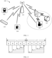
- FIG. 1 is a schematic diagram of a communication system 100 to which a method provided in an embodiment of this application is applicable.
- the communication system 100 may include at least one access network device, for example, an access network device 101 shown in FIG. 1 .
- the communication system 100 may further include at least one terminal device, for example, terminal devices 102 to 107 shown in FIG. 1 .
- the terminal devices 102 to 107 may be mobile or stationary.
- the access network device 101 may communicate with one or more of the terminal devices 102 to 107 over a radio link.
- Each access network device can provide communication coverage for a particular geographic area, and may communicate with a terminal device located in the coverage area. For example, the access network device may send configuration information to the terminal device, and the terminal device may send uplink data to the access network device based on the configuration information. For another example, the access network device may send downlink data to the terminal device. Therefore, the access network device 101 and the terminal devices 102 to 107 in FIG. 1 constitute a communication system.
- the terminal devices may communicate with each other directly.
- direct communication between the terminal devices may be implemented using a D2D technology or the like.
- the terminal devices 105 and 106 may directly communicate with each other using the D2D technology, and the terminal devices 105 and 107 may directly communicate with each other using the D2D technology.
- the terminal device 106 and the terminal device 107 may communicate with the terminal device 105 separately or simultaneously.
- the terminal devices 105 to 107 may alternatively communicate with the access network device 101 separately.
- the terminal devices 105 to 107 may communicate with the access network device 101 directly.
- the terminal devices 105 and 106 in FIG. 1 may communicate with the access network device 101 directly.
- the terminal devices 105 to 107 may communicate with the access network device 101 indirectly.
- the terminal device 107 in FIG. 1 communicates with the access network device 101 via the terminal device 105.
- FIG. 1 shows an example of one access network device, a plurality of terminal devices, and communication links between the communication devices.
- the communication system 100 may include a plurality of access network devices, and in a coverage area of each access network device, another quantity of terminal devices, for example, more or fewer terminal devices, may be included. This is not limited in this application.
- the foregoing communication devices may include an encoding device.
- the access network device 101 may perform encoding and output an encoded sequence, and the encoded sequence is transmitted to the terminal device 102 in FIG. 1 on a channel after processing such as modulation, rate matching, or interleaving is performed on the encoded sequence.
- the terminal device 102 includes a decoder, configured to decode the received encoded sequence.
- a plurality of antennas may be configured for the access network device 101 and the terminal devices 102 to 107 in FIG. 1 .
- the plurality of antennas may include at least one transmit antenna for sending a signal and at least one receive antenna for receiving a signal.
- each communication device further additionally includes a transmitter chain and a receiver chain.
- the transmitter chain and the receiver chain each may include a plurality of components (for example, a processor, a modulator, a multiplexer, a demodulator, a demultiplexer, or an antenna) related to signal transmission and reception.
- the wireless communication system 100 may further include other network entities such as a network controller or a mobility management entity. No limitation is set thereto in this embodiment of this application.
- HARQ technology is a technology that combines FEC and ARQ.
- a transmitting end may add redundant information when sending data, so that the receiving end can correct some errors.
- the receiving end may request, by using an ARQ mechanism, the transmitting end to retransmit the data.
- the receiving end uses an error check code, for example, a cyclic convolutional code (cyclic redundancy check, CRC) check code, to detect whether an error occurs in a data packet in a decoding process. If no error occurs, the receiving end may return ACK to the transmitting end, to indicate that the data packet has been correctly received. After receiving the ACK, the transmitting end may continue to send a next data packet. If an error occurs, the receiving end may discard the data packet, and return NAK to the transmitting end, to indicate that the data packet is not successfully received. Therefore, after receiving the NAK, the transmitting end may resend the same data packet to the receiving end.
- CRC cyclic convolutional code
- negative-acknowledgement may also be abbreviated as NACK information.
- the HARQ technology with soft combining may also be used.
- the data packet is not discarded as a whole. Instead, useful information in the data packet that cannot be correctly decoded is stored in a HARQ buffer, and the useful information is combined with a subsequently retransmitted data packet, that is, a soft combining process.
- the combined data packet is decoded. If the combined data packet still cannot be correctly decoded, the process of requesting retransmission and soft combining may be repeated.
- Embodiments of this application are applicable to the HARQ technology with soft combining.
- the HARQ technology with soft combining can be classified into the following two types: chase combining (chase combining) and incremental redundancy (incremental redundancy).
- chase combining means that the bit information of the retransmitted data is the same as that of the originally transmitted data
- incremental redundancy means that the bit information of the retransmitted data is different from that of the originally transmitted data.
- Embodiments of this application are applicable to the two types of HARQ technologies with soft combining.
- the HARQ technology can be classified into the following two types: synchronous HARQ and asynchronous HARQ.
- the synchronous HARQ means that a moment for retransmitting data is a fixed moment after previously retransmitting data.
- the transmitting end can retransmit data only in a specific subframe by using a specific HARQ process number. Therefore, a HARQ process number of the retransmitted data may be deduced from the system frame number or subframe number, and it does not need to explicitly send a HARQ process number.
- the asynchronous HARQ means that a moment for retransmitting data may be any moment. In other words, in the asynchronous HARQ, the transmitting end may retransmit data by using a HARQ process number in any sequence, so that scheduling flexibility can be improved.
- the HARQ technology may be applied to an uplink data transmission scenario, or may be applied to a downlink data transmission scenario.
- an access network device feeds back ACK or NAK information corresponding to uplink data to a UE.
- the ACK or NAK information arrives at the UE after a specific downlink transmission delay.
- the UE demodulates and processes the ACK or NAK information, retransmits data based on the ACK or NAK information, and the data arrives at the access network device after a specific uplink transmission delay.
- the access network device processes the uplink retransmitted data after a specific processing delay, and feeds back the ACK or NAK information for the retransmitted data to the UE again.
- a period from a time when the access network device feeds back the ACK or NAK information to the UE to a time when the access network device completes processing of the retransmitted data may be understood as a HARQ round-trip time (round-trip time, RTT).
- the UE feeds back ACK or NAK information to the access network device.
- the ACK or NAK information arrives at the access network device after a specific uplink transmission delay.
- the access network device demodulates and processes the ACK or NAK information, retransmits the data based on the ACK or NAK information, and the data arrives at the UE after a specific downlink transmission delay.
- the UE processes the downlink retransmitted data after a specific processing delay, and feeds back the ACK or NAK information for the retransmitted data to the access network device again. Therefore, a period from a time when the UE feeds back the ACK or NAK information to the access network device to a time when the UE completes processing of the retransmitted data may be understood as a HARQ RTT.
- a time difference between a time when the transmitting end transmits data and a time when the receiving end feeds back ACK or NAK information is specified and unique.
- downlink data transmission is used as an example below.
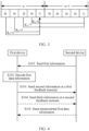
- FIG. 2 and FIG. 3 are schematic diagrams of possible HARQ timing feedback.
- a time division duplex (time division duplex, TDD) frame structure DDDDU is used as an example, where D represents a downlink timeslot, and U represents an uplink timeslot.
- the UE If the UE detects a physical downlink shared channel (physical downlink shared channel, PDSCH) in timeslot n, or if the UE detects a downlink control information (downlink control information, DCI) released by semi-persistent scheduling (semi-persistent scheduling, SPS) in timeslot n, the UE sends responsive ACK or NAK information in timeslot (n+K 1 ).
- K 1 may be obtained by using a PDSCH-to-HARQ feedback timing indicator in the DCI, or may be obtained by using a parameter DI-DataToUL-ACK.
- the timing indicator is 3 bits, and may correspondingly indicate that a value of K 1 is ⁇ 1, 2, 3, 4, 5, 6, 7, 8 ⁇ .
- the timer may be 0 bits, 1 bit, 2 bits, or 3 bits, and the bit width thereof may be determined by [log 2 (I)], where parameter I may be determined by the number of rows of the parameter DI-DataToUL-ACK.
- Table 1 shows a configuration manner of the PDSCH-to-HARQ feedback timing indicator.
- Table 1 PDSCH-to-HARQ feedback timing indicator Quantity of timeslots 1 bit 2 bits 3 bits '0' '00' '000' First timing value of dl-DataToUL-ACK '1' '01' '001' Second timing value of dl-DataToUL-ACK '10' '010' Third timing value of dl-DataToUL-ACK '11' '011' Fourth timing value of dl-DataToUL-ACK '100' Fifth timing value of dl-DataToUL-ACK '101' Sixth timing value of dl-DataToUL-ACK '110' Seventh timing value of dl-DataToUL-ACK '111' Eighth timing value of dl-DataToUL-ACK
- the receiving end may decode the data in another mode.
- an excessively short timing may cause the receiving end to have no opportunity to use another mode.
- a proper increase in the number of iterations may increase a decoding time, but may improve decoding performance.
- An excessively short timing may cause unnecessary decoding termination, and performance of iterative decoding cannot be achieved.
- This application provides a data processing method, to reduce a latency of transmitting data.
- a first device is a terminal device, and a second device is an access network device; or a first device is an access network device, and a second device is a terminal device; or a first device is a terminal device, and a second device is a terminal device; or a first device is an access network device, and a second device is an access network device.
- the first device and the second device may be a master-slave device or an equivalent device in any wireless communication system.
- a moment in embodiments of this application may be obtained by using a frame number, a subframe number, a slot sequence number, or a symbol sequence number corresponding to the moment. This is not limited in this application.
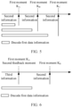
- FIG. 4 is a schematic flowchart of data processing according to an embodiment of this application.
- a first device receives first information from a second device, and correspondingly, the second device sends the first information to the first device.
- the first information indicates a plurality of first moments
- the plurality of first moments are used by the first device to send second information to the second device
- the second information indicates a result of decoding first data information by the first device.
- the plurality of first moments are moments at which the first device can send the second information to the second device.
- the second information is ACK or NAK information.
- the first information may explicitly indicate values of the plurality of first moments.
- the first information is carried in DCI in physical downlink control channel (physical downlink control channel, PDCCH), and the second device may indicate values of the plurality of first moments by using the DCI.
- Table 2 shows an example in which one bit in the DCI is used to indicate two first moments K A , K B .
- Table 3 shows an example in which two bits in the DCI are used to indicate two first moments K A , K B .
- Table 4 shows an example in which three bits in the DCI are used to indicate three first moments K A , K B , and K C .
- the first information may implicitly indicate values of the plurality of first moments.
- the first information is a correspondence between the DCI and radio resource control (radio resource control, RRC) signaling.
- the second device may use the DCI to represent an index number, and a specific value is indicated by using RRC signaling.
- Table 5 shows a configuration manner in which values of the plurality of first moments are indicated by using RRC signaling.
- the second device may determine specific values of the plurality of first moments based on a current service, procedure, or bearer status.
- a timeslot number is used to represent the first moment. For example, if the first device receives the first information in the n th timeslot, and a value of a first moment in the plurality of first moments is K A , it indicates that the first device can send the second information to the second device in the (n+K A ) th timeslot.
- a manner of representing the first moment is not limited in this application.
- the plurality of first moments include a second feedback moment
- the second feedback moment is a moment at which the first device needs to send the second information to the second device.
- the first information may explicitly indicate which first moment in the plurality of first moments is the second feedback moment.
- which first moment in the plurality of first moments is the second feedback moment may be determined in a preconfigured manner.
- the first device may feed back the second information to the second device at the second feedback moment based on a status of decoding the first data information at the second feedback moment, so that the second device can sense a decoding status of the first device in advance, thereby improving a network sensing rate.
- S102 The first device decodes the first data information.
- the second device sends the first data information to the first device.
- the first device has one or more decoding manners.
- the first device may attempt to decode the first data information in another decoding manner.
- a decoding manner of the first device is an algorithm such as iterative decoding, successive cancellation list-flip decoding (successive cancellation list-flip decoding, SCLF), belief propagation (Belief Propagation, BP), or the like.
- the first device sends the second information to the second device at a first feedback moment, and correspondingly, the second device receives the second information from the first device at the first feedback moment.
- the first feedback moment is a moment in the plurality of first moments.
- the first feedback moment is a 1 st first moment in the plurality of first moments that is after the first device completes decoding of the first data information.
- the first information indicates the first moment K A and K B , and K A ⁇ K B .
- the first device may send the second information to the second device at the first moment K A .
- the first device may feed back a result of decoding the first data information, for example, ACK or NAK information, so that the second device may release a reserved resource of the first moment K B after receiving the second information at the first moment K A .
- the first device may send the second information to the second device at the first moment K B .
- the first device may send the second information, for example, NAK, to the second device at the first moment K B .
- the first information indicates the first moment K A , K B , and Kc, and K A ⁇ K B ⁇ K C . If the first device completes decoding of the first data information before the first moment K A , the first device may send the second information to the second device at the first moment K A . To be specific, the first device may feed back a result of decoding the first data information, for example, ACK or NAK. If the first device completes decoding of the first data information before the first moment K B and after the first moment K A , the first device may send the second information to the second device at the first moment K B .
- the first device may send the second information to the second device at the first moment Kc. If the first device still does not complete decoding of the first data information at the second moment Kc, the first device may send the second information, for example, NAK information, to the second device at the first moment Kc.
- the second information for example, NAK information
- the first device stops decoding, and sends the second information, for example, NAK information, to the second device at the last first moment.
- That the first device completes decoding of the first data information may be explained in the following two manners.
- the first device successfully decodes the first data information. For example, if the first device successfully decodes the first data information before the first moment K A , the first device may send the second information, for example, ACK information, to the second device at the first moment K A .
- the second information for example, ACK information
- the first device has at least one manner of decoding the first data information, and the first device decodes the first data information unsuccessfully in all manners. For example, if the first device decodes, before the first moment K A , the first data information unsuccessfully in a manner that can be used, the first device may feed back NAK to the second device at the first moment K A .
- the first device may feed back ACK to the second device at the first moment K A ; or if the first device has not successfully decoded the first data information in a manner that can be used, the first device may feed back NAK to the second device at the first moment K A . If the first device still performs decoding at the first moment K A , that is, the first device has not completed decoding, or the first device performs decoding unsuccessfully in a manner but still does not attempt to perform decoding in another manner, the first device may not send the second information to the second device at the first moment K A .
- S104 The first device sends third information to the second device at the second feedback moment, and correspondingly, the second device receives the third information from the first device at the second feedback moment.
- the third information indicates whether the first device completes decoding of the first data information at the second feedback moment.
- the first device may feed back the second information to the second device at the second feedback moment based on a status of decoding the first data information at the second feedback moment, so that the second device can sense a decoding status of the first device in advance, thereby improving a network sensing rate.
- the first information indicates a plurality of first moments K A and K B , where the first moment K A is the second feedback moment, and K A ⁇ K B . If the first device completes decoding of the first data information before the second feedback moment, the second feedback moment and the first feedback moment are a same moment, and the second information and the third information are same information. Therefore, the first device feeds back the result of decoding the first data information at the second feedback moment, for example, the ACK or NAK information. If the first device has not completed decoding of the first data information at the second feedback moment, the first device sends the third information, for example, the NAK information, to the second device at the second feedback moment.
- the first device does not stop decoding the first data information, but continues decoding.
- the second device does not immediately start data retransmission even if the second device receives the NAK information at the second feedback moment. If the first device completes decoding of the first data information after the second feedback moment K A and before the first moment K B , the first device still feeds back the second information to the second device at the first moment K B , or if the first device still does not complete decoding of the first data information at the first moment K B , the first device feeds back the second information to the second device at the first moment K B .
- the second feedback moment is a 1 st first moment in the plurality of first moments that is after the first device completes decoding of the first data information, that is, the first feedback moment, the second information and the third information has same content, and the result of decoding needs to be fed back only once.
- the second device sends the retransmitted first data information to the first device based on the second information.
- the first device receives the retransmitted first data information from the second device.
- bit information of the first data information that is retransmitted may be the same as or different from that of the first data information that is originally sent. This is not limited in this application.
- the second device may configure a plurality of first moments for the first device, and the first moment may determine the first feedback moment from the plurality of first moments based on a decoding status of the first moment, and feed back the second information to the second device at the first feedback moment. Therefore, flexibility of feeding back, by the second device, a result of decoding data information is improved, and a latency of transmitting the data information by a system is reduced.
- FIG. 7 is a schematic flowchart of another data processing method.
- S201 The first device decodes the first data information.
- the first device has one or more decoding manners.
- the first device may attempt to decode the first data information in another decoding manner.
- a decoding mode of the first device is an algorithm such as iterative decoding, BP, SCLF, or the like.
- the first device When the first device does not complete decoding of the first data information at a first feedback moment, in S202, the first device sends first request information to a second device at the first feedback moment, and correspondingly, the second device receives the first request information sent by the first device at the first feedback moment.
- the first request information indicates the first device to delay feeding back, to the second device, a result of decoding the first data information by the first device.
- the first device may continue to decode the first data information, and send the first request information for delaying feedback to the second device.
- the first device receives feedback indication information from the second device, and correspondingly, the second device sends the feedback indication information to the first device.
- the feedback indication information indicates the first device to feed back the result of decoding the first data to the second device at the first feedback moment.
- the first device has successfully completed decoding of the first data information at the first feedback moment.
- the first device has determined, at the first feedback moment, that the decoding the first data information is unsuccessful.
- the first device has decoded the first data information in a decoding manner that can be used, but the decoding is unsuccessful.
- the first device has not completed decoding of the first data information at the first feedback moment.
- the first device is decoding the first data information in a manner at the first feedback moment, and the decoding has not been completed.
- the first device decodes the first data unsuccessfully in a manner, but the first device may decode the first data information in another manner.
- the first device has completed decoding of the first data information, that is, the first device has determined, at the first feedback moment, the result of decoding the first data information.
- the first device sends acknowledgement information, for example, ACK information, to the second device.
- the first device sends negative-acknowledgement, for example, NAK information, to the second device.
- the first device sends the first request information to the second device, where the first request information indicates the first device to continue decoding the first data information after the first feedback moment.
- the first request information may be temporary negative-reply information, for example, temporary negative-acknowledgement (temporary negative-acknowledgement, TNAK) information.
- the first device does not stop decoding the first data information at the first feedback moment, but continues decoding and notifies the second device that the decoding is continued.
- the first device may further request to obtain an opportunity of feeding back the result of decoding again.
- the first device when the first device has completed decoding of the first data information at the first feedback moment, the first device sends acknowledgement information or negative-acknowledgement information, for example, ACK or NAK information, to the second device.
- acknowledgement information for example, ACK or NAK information
- the second device may clear the first data information, for example, a corresponding HARQ process, and continue to transmit subsequent data information.
- the second device receives the negative-acknowledgement information
- the second device retransmits the first data information. For example, the second device performs HARQ based on the corresponding HARQ process.
- the first device When the first device does not complete decoding of the first data information at the first feedback moment, the first device sends the first request information to the second device, and the second device does not immediately transmit the subsequent data information or immediately retransmit the first data information, but determines to perform different actions based on different cases.
- the first device sends second request information to the second device at the first feedback moment, and correspondingly, the second device receives the second request information sent by the first device at the first feedback moment.
- the second request information indicates a first recommended moment, where the first recommended moment is a moment at which the first device estimates that decoding of the first data information can be completed.
- the first device may estimate, based on a decoding status of the first device, a moment at which decoding the first data information is completed. Therefore, the second device may also determine, based on the first recommended moment, an action to be performed.
- the first device may explicitly send the first request information.
- the first request information for example, the TNAK information
- 2 bits may be used to represent the ACK information, the NAK information, or the TNAK information respectively.
- a corresponding field may be defined on the PUCCH to represent the first recommended moment Kt. Table 6 shows an example of explicitly representing the first recommended moment Kt.
- Table 6 Field used to indicate a first recommended moment K t Corresponding timing information 1 bit 2 bits 3 bits Explicit representation High-layer indication '0' '00' '000' 0 1st RRC signaling indication value '1' '01' '001' 1 2nd RRC signaling indication value '10' '010' 2 3rd RRC signaling indication value '11' '011' 3 4th RRC signaling indication value '100' 4 5th RRC signaling indication value '101' 5 6th RRC signaling indication value '110' 6 7th RRC signaling indication value '111' 7 8th RRC signaling indication value
- the first device may implicitly send the first request information.
- the TNAK information when the first request information, for example, the TNAK information, is carried on the PUCCH, whether the TNAK information exists may be determined depending on whether a field used to indicate the first recommended moment Kt exists in the PUCCH, and 1 bit is used to represent the ACK or NAK information. If the field used to indicate the first recommended moment Kt exists in the PUCCH, it indicates that the NAK information is the TNAK information. If the field used to indicate the first recommended moment Kt does not exist in the PUCCH, it indicates that there is no TNAK information. Table 7 shows an example of implicitly representing the first recommended moment Kt.
- Table 7 Field used to indicate a first recommended moment K t Corresponding timing information 1 bit 2 bits 3 bits Explicit representation High-layer indication '0' '00' '000' 0 1st RRC signaling indication value '1' '01' '001' 1 2nd RRC signaling indication value '10' '010' 2 3rd RRC signaling indication value '11' '011' 3 4th RRC signaling indication value '100' 4 5th RRC signaling indication value '101' 5 6th RRC signaling indication value '110' 6 7th RRC signaling indication value '111' 7 8th RRC signaling indication value
- the second feedback moment is a moment at which the first device sends feedback information to the second device, and the feedback information indicates a result of decoding the first data information by the first device at the second feedback moment.
- the first device receives indication information from the second device, and correspondingly, the second device sends the indication information to the first device.
- the indication information indicates the second feedback moment.
- the second device determines the second feedback moment based on the first request information.
- the second device determines the second feedback moment based on a current service, an application, a bearer, or a requirement of an upper layer.
- the second device may also indicate, based on the current service, the application, the bearer, or the requirement of the upper layer, the first device not to continue decoding the first data information, but directly retransmit the first data information, or alternatively, abandon the first data information and continue to transmit subsequent information.
- the second device may determine the second feedback moment based on the first recommended moment.
- the second feedback moment may be earlier than the first recommended moment, or may be later than the first recommended moment. This is not limited in this application.
- the first device may determine the second feedback moment based on the decoding status of the first device, and the first request information further indicates the second feedback moment.
- the first device may determine the second feedback moment based on the decoding status of the first device, and feed back the second feedback moment to the second device.
- the second device performs monitoring at the second feedback moment to obtain the result of decoding the first digital data by the first device.
- the first device sends the feedback information to the second device at the second feedback moment, and correspondingly, the second device receives the feedback information sent by the first device at the second feedback moment.
- the feedback information indicates the result of decoding the first data information by the first device at the second feedback moment.
- the second device sends the feedback indication information to the first device, where the feedback indication information further indicates a first feedback moment K 1 .
- the first device decodes the first data information. If the first device completes decoding of the first data information before the first feedback moment K 1 , the first device feeds back the acknowledgement information or the negative-reply information, for example, the ACK or NAK information, to the second device at the first feedback moment K 1 . If the first device does not complete decoding of the first data information at the first feedback moment K 1 , the first device sends first request information to the second device at the first feedback moment K 1 .
- the first request information indicates the first device to delay feeding back, to the second device, the result of decoding the first data information by the first device, for example, the TNAK information.
- the first request information further indicates the first recommended moment Kt.
- the second device determines a second feedback moment K d based on the first request information and a current scheduling status, and sends, to the first device, indication information used to feed back the second feedback moment K d .
- the first device does not stop decoding the first data information before the first feedback moment K 1 . If the first device completes decoding of the first data information before the second feedback moment K d , the first device sends the feedback information, for example, the ACK or NAK information, to the second device at the second feedback moment K d .
- the first device may send negative-reply information, for example, the NAK information, to the second device at the second feedback moment K d , and the second device may determine, at the second feedback moment, whether to retransmit the first data information.
- negative-reply information for example, the NAK information
- the first device may send the first request information to the second device at the first feedback moment at which the result of decoding should be fed back to the second device, to delay feeding back the result of decoding the first data information to the second device. Therefore, the first device may obtain more time to attempt to decode the first data information, to avoid unnecessary retransmission, and reduce a latency of transmitting data by a system.
- FIG. 9 is a schematic flowchart of another data processing method.
- a first device sends capability information to a second device, and correspondingly, the second device receives the capability information from the first device.
- the capability information indicates a decoding capability of the first device.
- the capability information may be a manner, performance, a load status, or the like in which the first device supports decoding the first data information.
- the capability information may be a correspondence between a quantity of iterations and decoding performance.
- the capability information may be explicitly sent to the second device.
- a correspondence between the first device and the capability information may be preconfigured.
- the second device may obtain the decoding capability of the first device based on the device type of the first device.
- the second device determines condition information based on the capability information.
- the second device determines the condition information based on the reliability and/or latency requirement and the capability information of the first device.
- the second device may determine a target of a current reliability and/or latency requirement based on a current scenario, a service, a transport block (transport block, TB), a code block group (code block group, CBG), or the like.
- the target may be met by adjusting a quantity of iterations.
- the quantity of iterations may be appropriately increased.
- a proper quantity of iterations may be selected based on a latency during retransmission on an air interface or a latency introduced by iterations of the first device.
- the first condition is that the first device does not complete decoding of the first data information at a first defined moment.
- the first condition is that the first device decodes the first data information in an iterative decoding manner, and a quantity of iterations reaches a first threshold.
- the first device receives the condition information from the second device, and correspondingly, the second device receives the condition information from the first device.
- the condition information indicates a condition for the first device to stop decoding the first data information.
- the second device may determine the condition information based on the reliability and/or latency requirement, or may determine the condition information based on the capability information of the first device, or may determine the condition information with reference to the reliability and/or latency requirement and the capability information of the first device.
- the second device may determine a first defined moment based on a service, an application, a bearer, or a requirement of an upper layer, for example, a requirement for a freshness degree.
- the first device may stop decoding the first data information, and does not need to feed back a result of decoding the first data information to the second device.
- the second device does not need to retransmit the first data information.
- the second device directly discards the first data information that is timeout or expires, and in turn, processes information within the latency constraint range or within the information fresh period.
- the first device supports decoding the first data in an iterative decoding manner.
- the second device may determine a first threshold, that is, a maximum number of iterations for iterative decoding, based on the capability information of the first device, the service, the application, the bearer, or the requirement of the upper layer, and the like.
- the first device stops decoding the first data information when the number of iterations reaches the first threshold.
- the first device may choose to feed back the result of decoding the first data information to the second device based on requirements of different scenarios, so that the second device may retransmit the first data information.
- the first device may not need to feed back the result of decoding the first data information to the second device, and in turn, receive subsequent data information.
- Table 8 shows an example of the quantity of decoding of the first device, that is, the first threshold.
- the condition information may be indicated based on the service or the bearer, for example, a master cell group (master cell group, MCG) Split, a secondary cell group (secondary cell group, SCG), or an SCG Split.
- the condition information may be indicated explicitly based on DCI, or may be indicated based on DCI with reference to a parameter defined by the upper layer. Referring to Table 8, the condition information may be indicated based on other information. In other words, a manner of indicating the condition information is not limited in this application.
- the first device sends ACK or NAK information to the second device by default.
- the second device may send, to the first device, information indicates that feedback is not required, or may be preconfigured. If the information sent by the second device to the first device does not include a field used to indicate a feedback moment, it indicates that the first device does not need to feed back the result of decoding the first data information.
- S304 The first device decodes the first data information, and the first device stops decoding the first data information when the first condition is met.
- the first device has one or more decoding manners.
- the first device may attempt to decode the first data information in another decoding manner.
- a decoding mode of the first device is an algorithm such as iterative decoding, SC, SCL, SCLF, or the like.
- the first device decodes the first data information.
- the second device sends the condition information to the first device, where the condition information indicates a first condition, and the first condition is that the first device stops decoding the first data information at a first defined moment K m . If the first device does not complete decoding of the first data information at the first defined moment K m , the first device directly stops the decoding, and does not need to feed back the result of decoding to the second device.
- the first device when the first condition is met for decoding the first data information, the first device may stop decoding the first data information.
- the first data information may be timeout, is expired, or does not meet a requirement, and the first device may directly discard the first data information, thereby reducing an unnecessary latency and reducing a latency of transmitting data by a system.
- FIG. 11 is a schematic block diagram of a data processing apparatus according to an embodiment of this application.
- the apparatus 1000 may include a processing unit 1100 and a transceiver unit 1200.
- the apparatus 1000 may correspond to the first device in the foregoing method embodiments, or a component (such as a circuit, a chip, a chip system, or the like) configured in the first device.
- a component such as a circuit, a chip, a chip system, or the like configured in the first device.
- the apparatus 1000 may correspond to the first device in the method according to embodiments of this application, and the apparatus 1000 may include units configured to perform the method performed by the first device in FIG. 4 .
- the units in the apparatus 1000 and the foregoing other operations and/or functions are separately intended to implement corresponding procedures in FIG. 4 .
- the processing unit 1100 may be configured to decode first data information.
- the transceiver unit 1200 may be configured to receive first information, where the first information indicates a plurality of first moments, the plurality of first moments are used by the first device to send second information to the second device, and the second information indicates a result of decoding first data information by the first device.
- the transceiver unit 1200 may be further configured to send the second information to the second device at a first feedback moment, and the first feedback moment is a moment in the plurality of first moments.
- the apparatus 1000 may correspond to the first device in the method according to embodiments of this application, and the apparatus 1000 may include units configured to perform the method performed by the first device in FIG. 7 .
- the units in the apparatus 1000 and the foregoing other operations and/or functions are separately intended to implement corresponding procedures in FIG. 7 .
- the processing unit 1100 may be configured to decode the first data information.
- the transceiver unit 1200 may be configured to send, by the first device, when the first device does not complete decoding of the first data information at the first feedback moment, first request information to the second device at the first feedback moment, where the first request information indicates the first device to delay feeding back the result of decoding the first data information by the first device to the second device, and the first feedback moment is a moment that is configured by the second device and at which the first device needs to feed back the result of decoding the first data information to the second device.
- the apparatus 1000 may correspond to the first device in the method according to embodiments of this application, and the apparatus 1000 may include units configured to perform the method performed by the first device in FIG. 9 .
- the units in the apparatus 1000 and the foregoing other operations and/or functions are separately intended to implement corresponding procedures in FIG. 9 .
- the processing unit 1100 may be configured to decode the first data information, and the processing unit 1100 may be further configured to stop decoding the first data information when the first condition is met.
- the transceiver unit 1200 may be configured to receive condition information, where the condition information indicates the first condition, and the first condition is a condition for the first device to stop decoding the first data information.
- the transceiver unit 1200 in the apparatus 1000 may be implemented by using a transceiver, for example, may correspond to the transceiver 2020 in the apparatus 2000 shown in FIG. 12 or a transceiver 3020 in a first device 3000 shown in FIG. 13 .
- the processing unit 1100 in the apparatus 1000 may be implemented by using at least one processor, for example, may correspond to the processor 2010 in the apparatus 2000 shown in FIG. 12 or the processor 3010 in the first device 3000 shown in FIG. 13 .
- the transceiver unit 1200 in the apparatus 1000 may be implemented by an input/output interface, a circuit, or the like; and the processing unit 1100 in the apparatus 1000 may be implemented by a processor, a microprocessor, an integrated circuit, or the like integrated in the chip or chip system.
- the apparatus 1000 may correspond to the second device in the method according to embodiments of this application, and the apparatus 1000 may include units configured to perform the method performed by the second device in FIG. 4 .
- the units in the apparatus 1000 and the foregoing other operations and/or functions are separately intended to implement corresponding procedures in FIG. 4 .
- the transceiver unit 1200 may be configured to send first data information.
- the transceiver unit 1200 may be further configured to send first information, where the first information indicates a plurality of first moments, the plurality of first moments are used by the first device to send second information to the second device, and the second information indicates a result of decoding first data information by the first device.
- the transceiver unit 1200 may be further configured to send the second information at a first feedback moment, and the first feedback moment is a moment in the plurality of first moments.
- the apparatus 1000 may correspond to the second device in the method according to embodiments of this application, and the apparatus 1000 may include units configured to perform the method performed by the second device in FIG. 7 .
- the units in the apparatus 1000 and the foregoing other operations and/or functions are separately intended to implement corresponding procedures in FIG. 7 .
- the transceiver unit 1200 may be configured to send first data information, and the transceiver unit 1200 may be further configured to receive first request information sent by the first device at the first feedback moment, where the first request information indicates the first device to delay feeding back the result of decoding the first data information by the first device to the second device, and the first feedback moment is a moment that is configured by the second device and at which the first device needs to feed back the result of decoding the first data information to the second device.
- the apparatus 1000 may correspond to the second device in the method according to embodiments of this application, and the apparatus 1000 may include units configured to perform the method performed by the second device in FIG. 9 .
- the units in the apparatus 1000 and the foregoing other operations and/or functions are separately intended to implement corresponding procedures in FIG. 9 .
- the transceiver unit 1200 may be configured to send first data information, and the transceiver unit 1200 may be further configured to send condition information, where the condition information indicates the first condition, and the first condition is a condition for the first device to stop decoding the first data information. It should be understood that a specific process in which the units perform the foregoing corresponding steps is described in detail in the foregoing method embodiments, and for brevity, details are not described herein.
- the transceiver unit 1200 in the apparatus 1000 may be implemented by using a transceiver, for example, may correspond to the transceiver 2020 in the apparatus 2000 shown in FIG. 12 or a transceiver 3020 in a second device 3000 shown in FIG. 13 .
- the processing unit 1100 in the apparatus 1000 may be implemented by using at least one processor, for example, may correspond to the processor 2010 in the apparatus 2000 shown in FIG. 12 or the processor 3010 in the second device 3000 shown in FIG. 13 .
- the transceiver unit 1200 in the apparatus 1000 may be implemented by an input/output interface, a circuit, or the like; and the processing unit 1100 in the apparatus 1000 may be implemented by a processor, a microprocessor, an integrated circuit, or the like integrated in the chip or chip system.
- FIG. 12 is another schematic block diagram of an apparatus 2000 according to an embodiment of this application.
- the apparatus 2000 includes a processor 2010, a transceiver 2020, and a memory 2030.
- the processor 2010, the transceiver 2020, and the memory 2030 communicate with each other via an internal connection path.
- the memory 2030 is configured to store instructions.
- the processor 2010 is configured to execute the instructions stored in the memory 2030, to control the transceiver 2020 to send a signal and/or receive a signal.
- the processor 2010 and the memory 2030 may be integrated together.
- the apparatus 2000 may correspond to the second device or the first device in the foregoing method embodiments, and may be configured to perform steps and/or procedures performed by the second device or the first device in the foregoing method embodiments.
- the memory 2030 may include a read-only memory and a random access memory, and provide instructions and data to the processor. A part of the memory may further include a non-volatile random access memory.
- the memory 2030 may be a separate component, or may be integrated in the processor 2010.
- the processor 2010 may be configured to execute the instructions stored in the memory 2030, and when the processor 2010 executes the instructions stored in the memory, the processor 2010 is configured to perform the steps and/or the procedures corresponding to the second device or the first device in the foregoing method embodiments.
- the apparatus 2000 is the first device in the foregoing embodiment.
- the apparatus 2000 is the second device in the foregoing embodiment.
- the transceiver 2020 may include a transmitter and a receiver.
- the transceiver 2020 may further include an antenna. There may be one or more antennas.
- the processor 2010, the memory 2030, and the transceiver 2020 may be devices integrated in different chips.
- the processor 2010 and the memory 2030 may be integrated in a baseband chip, while the transceiver 2020 may be integrated in a radio frequency chip.
- the processor 2010, the memory 2030, and the transceiver 2020 may alternatively be devices integrated in a same chip. This is not limited in this application.
- the apparatus 2000 is a component configured in the first device, for example, a circuit, a chip, or a chip system.
- the apparatus 2000 is a component configured in the second device, for example, a circuit, a chip, or a chip system.
- the transceiver 2020 may alternatively be a communication interface, for example, an input/output interface or a circuit.
- the transceiver 2020, the processor 2010, and the memory 2020 may all be integrated in a same chip, for example, integrated in a baseband chip.
- FIG. 13 is a schematic diagram of a structure of a terminal device 3000 according to an embodiment of this application.
- the terminal device 3000 may be applied to the system shown in FIG. 1 , to perform a function of the first device or the second device in the foregoing method embodiments.
- the terminal device 3000 includes a processor 3010 and a transceiver 3020.
- the terminal device 3000 further includes a memory 3030.
- the processor 3010, the transceiver 3020, and the memory 3030 may communicate with each other via an internal connection path, to transfer a control signal and/or a data signal.
- the memory 3030 is configured to store a computer program.
- the processor 3010 is configured to invoke the computer program from the memory 3030 and run the computer program, to control the transceiver 3020 to receive/send a signal.
- the terminal device 3000 may further include an antenna 3040, configured to send, by using a radio signal, uplink data or uplink control signaling output by the transceiver 3020.
- the processor 3010 and the memory 3030 may be combined into a processing apparatus.
- the processor 3010 is configured to execute program code stored in the memory 3030, to implement the foregoing function.
- the memory 3030 may be alternatively integrated in the processor 3010, or may be independent of the processor 3010.
- the processor 3010 may correspond to the processing unit 1100 in FIG. 11 or the processor 2010 in FIG. 12 .
- the transceiver 3020 may correspond to the transceiver unit 1200 in FIG. 11 or the transceiver 2020 in FIG. 12 .
- the transceiver 3020 may include a receiver (which is also referred to as a receiver machine or a receiver circuit) and a transmitter (which is also referred to as a transmitter machine or a transmitter circuit).
- the receiver is configured to receive a signal
- the transmitter is configured to transmit a signal.
- the terminal device 3000 shown in FIG. 13 can implement each process performed by the terminal device in the method embodiment shown in FIG. 2 .
- Operations and/or functions of the modules in the terminal device 3000 are separately intended to implement corresponding procedures in the foregoing method embodiments.
- the processor 3010 may be configured to perform an action that is implemented inside the terminal device and that is described in the foregoing method embodiments
- the transceiver 3020 may be configured to perform an action of sending or receiving that is performed by the terminal device to or from the access network device and that is described in the foregoing method embodiments.
- the terminal device 3000 may further include a power supply 3050, configured to supply power to various devices or circuits in the terminal device.
- a power supply 3050 configured to supply power to various devices or circuits in the terminal device.
- the terminal device 3000 may further include one or more of an input unit 3060, a display unit 3070, an audio circuit 3080, a camera 3090, a sensor 3100, and the like.
- the audio circuit may further include a speaker 3082, a microphone 3084, and the like.
- FIG. 14 is a schematic diagram of a structure of an access network device according to an embodiment of this application, for example, may be a schematic diagram of a structure of a base station.
- the base station 4000 may be applied to the system shown in FIG. 1 , to perform a function of the first device or the second device in the foregoing method embodiments.
- the base station 4000 may include one or more radio frequency units, such as a remote radio unit (remote radio unit, RRU) 4100 and one or more baseband units (BBU) 4200.
- the RRU 4100 may be referred to as a transceiver unit, and may correspond to the transceiver unit 1200 in FIG. 11 or the transceiver 2020 in FIG. 12 .
- the RRU 4100 may also be referred to as a transceiver machine, a transceiver circuit, a transceiver, or the like, and may include at least one antenna 4101 and a radio frequency unit 4102.
- the RRU 4100 may include a receiver unit and a transmitter unit.
- the receiver unit may correspond to a receiver (which is also referred to as a receiver machine or a receiver circuit).
- the transmitter unit may correspond to a transmitter (which is also referred to as a transmitter machine or a transmitter circuit).
- the RRU 4100 part is mainly configured to receive and transmit radio frequency signals and perform conversion between a radio frequency signal and a baseband signal, for example, configured to send indication information to a terminal device.
- the BBU 4200 part is mainly configured to perform baseband processing, control the base station, and the like.
- the RRU 4100 and the BBU 4200 may be disposed together physically, or may be separately disposed physically, that is, a distributed base station.
- the BBU 4200 is a control center of the base station, may also be referred to as a processing unit, may correspond to the processing unit 1100 in FIG. 11 or the processor 2010 in FIG. 12 , and is mainly configured to perform baseband processing functions such as channel encoding, multiplexing, modulation, and spectrum spreading.
- the BBU (the processing unit) may be configured to control the base station to perform an operation procedure related to the access network device in the foregoing method embodiments, for example, generate the indication information.
- the BBU 4200 may include one or more boards.
- the plurality of boards may jointly support a radio access network (for example, an 5G network) that uses a single access standard, or may separately support radio access networks (for example, an LTE network, a 5G network, or another network) that use different access standards.
- the BBU 4200 further includes a memory 4201 and a processor 4202.
- the memory 4201 is configured to store necessary instructions and data.
- the processor 4202 is configured to control the base station to perform a necessary action, for example, configured to control the base station to perform an operation procedure related to the access network device in the foregoing method embodiments.
- the memory 4201 and the processor 4202 may serve one or more boards. In other words, a memory and a processor may be disposed on each board. Alternatively, a plurality of boards may share a same memory and a same processor. In addition, a necessary circuit may further be disposed on each board.
- the base station 4000 shown in FIG. 14 can implement each process related to the access network device in the method embodiments. Operations and/or functions of the modules in the base station 4000 are separately intended to implement corresponding procedures in the foregoing method embodiments. For details, refer to the descriptions in the foregoing method embodiments. To avoid repetition, detailed descriptions are properly omitted herein.
- the BBU 4200 may be configured to perform an action that is implemented inside the access network device and that is described in the foregoing method embodiments.
- the RRU 4100 may be configured to perform an action that is of the access network device sending information to or receiving information from the terminal device and that is described in the foregoing method embodiments. For details, refer to the descriptions in the foregoing method embodiments. Details are not described herein again.
- the base station 4000 shown in FIG. 14 is merely a possible form of the access network device, and shall not constitute any limitation on this application.
- the method provided in this application is applicable to other forms of access network device.
- the network device includes an AAU, and may further include a CU and/or a DU; includes a BBU and an adaptive radio unit (adaptive radio unit, ARU); or includes a BBU.
- the network device may be customer premises equipment (customer premises equipment, CPE), or may be in another form.
- a specific form of the access network device is not limited in this application.
- the CU and/or the DU may be configured to perform an action that is implemented inside the access network device and that is described in the foregoing method embodiments.
- the AAU may be configured to perform an action that is of the access network device sending information to or receiving information from the terminal device and that is described in the foregoing method embodiments.
- This application further provides a processing apparatus, including at least one processor.
- the at least one processor is configured to execute a computer program stored in a memory, so that the processing apparatus performs the method performed by the terminal device or the access network device in any one of the foregoing method embodiments.
- An embodiment of this application further provides a processing apparatus, including a processor and a communication interface.
- the communication interface is coupled to the processor.
- the communication interface is configured to input and/or output information.
- the information includes at least one of instructions and data.
- the processor is configured to execute a computer program, so that the processing apparatus performs the method performed by the terminal device or the access network device in any one of the foregoing method embodiments.
- An embodiment of this application further provides a processing apparatus, including a processor and a memory.
- the memory is configured to store a computer program.
- the processor is configured to invoke the computer program from the memory and run the computer program, so that the processing apparatus performs the method performed by the terminal device or the access network device in any one of the foregoing method embodiments.
- the processing apparatus may be one or more chips.
- the processing apparatus may be a field programmable gate array (field programmable gate array, FPGA), an application-specific integrated chip (application-specific integrated circuit, ASIC), a system on chip (system on chip, SoC), a central processing unit (central processing unit, CPU), a network processor (network processor, NP), a digital signal processing circuit (digital signal processor, DSP), a microcontroller (micro controller unit, MCU), a programmable controller (programmable logic device, PLD), or another integrated chip.
- field programmable gate array field programmable gate array
- ASIC application-specific integrated circuit
- SoC system on chip
- CPU central processing unit
- network processor network processor
- NP digital signal processing circuit
- DSP digital signal processor
- microcontroller micro controller unit, MCU
- programmable controller programmable logic device, PLD
- steps in the foregoing methods can be implemented by using a hardware integrated logical circuit in the processor, or by using instructions in a form of software.
- the steps of the method disclosed with reference to embodiments of this application may be directly performed by a hardware processor, or may be performed by using a combination of hardware in the processor and a software module.
- a software module may be located in a mature storage medium in the art, such as a random access memory, a flash memory, a read-only memory, a programmable read-only memory, an electrically erasable programmable memory, or a register.
- the storage medium is located in the memory, and a processor reads information in the memory and completes the steps in the foregoing methods in combination with hardware of the processor. To avoid repetition, details are not described herein again.
- the processor in embodiments of this application may be an integrated circuit chip, and has a signal processing capability.
- steps in the foregoing method embodiments can be implemented by using a hardware integrated logical circuit in the processor, or by using instructions in a form of software.
- the processor may be a general purpose processor, a digital signal processor (DSP), an application specific integrated circuit (ASIC), a field programmable gate array (FPGA) or another programmable logic device, a discrete gate or a transistor logic device, or a discrete hardware component. It may implement or perform the methods, the steps, and logical block diagrams that are disclosed in embodiments of this application.
- the general-purpose processor may be a microprocessor, or the processor may be any conventional processor or the like.
- Steps of the methods disclosed with reference to embodiments of this application may be directly executed and accomplished by using a hardware decoding processor, or may be executed and accomplished by using a combination of hardware and software modules in the decoding processor.
- a software module may be located in a mature storage medium in the art, such as a random access memory, a flash memory, a read-only memory, a programmable read-only memory, an electrically erasable programmable memory, or a register.
- the storage medium is located in the memory, and a processor reads information in the memory and completes the steps in the foregoing methods in combination with hardware of the processor.
- the memory in this embodiment of this application may be a volatile memory or a nonvolatile memory, or may include a volatile memory and a nonvolatile memory.
- the nonvolatile memory may be a read-only memory (read-only memory, ROM), a programmable read-only memory (programmable ROM, PROM), an erasable programmable read-only memory (erasable PROM, EPROM), an electrically erasable programmable read-only memory (electrically EPROM, EEPROM), or a flash memory.
- the volatile memory may be a random access memory (random access memory, RAM), used as an external cache.
- RAMs may be used, for example, a static random access memory (static RAM, SRAM), a dynamic random access memory (dynamic RAM, DRAM), a synchronous dynamic random access memory (synchronous DRAM, SDRAM), a double data rate synchronous dynamic random access memory (double data rate SDRAM, DDR SDRAM), an enhanced synchronous dynamic random access memory (enhanced SDRAM, ESDRAM), a synchronous link dynamic random access memory (synchlink DRAM, SLDRAM), and a direct rambus dynamic random access memory (direct rambus RAM, DR RAM).
- static random access memory static random access memory
- DRAM dynamic random access memory
- DRAM dynamic random access memory
- SDRAM synchronous dynamic random access memory
- double data rate SDRAM double data rate SDRAM
- DDR SDRAM double data rate SDRAM
- ESDRAM enhanced synchronous dynamic random access memory
- SLDRAM synchronous link dynamic random access memory
- direct rambus RAM direct rambus RAM
- this application further provides a computer program product.
- the computer program product includes computer program code.
- the computer program code When the computer program code is run on a computer, the computer is enabled to perform the method performed by the terminal device or the method performed by the network device in the embodiment shown in FIG. 3 .
- this application further provides a computer-readable storage medium.
- the computer-readable storage medium stores program code.
- the program code When the program code is run on a computer, the computer is enabled to perform the method performed by the terminal device or the method performed by the network device in the embodiment shown in FIG. 3 .
- this application further provides a system.
- the system includes the foregoing one or more terminal devices and the foregoing one or more network devices.
- the network device and the terminal device in the foregoing apparatus embodiments completely correspond to the network device and the terminal device in the method embodiments.
- a corresponding module or unit performs a corresponding step.
- the communication unit (the transceiver) performs a receiving or sending step in the method embodiments, and a step other than the sending step and the receiving step may be performed by the processing unit (the processor).
- the processing unit the processor
- the terminal device may be used as an example of a receiving device
- the network device may be used as an example of a sending device.
- the sending device and the receiving device may be both terminal devices or the like. Specific types of the sending device and the receiving device are not limited in this application.
- a component may be, but is not limited to, a process that runs on a processor, a processor, an object, an executable file, an execution thread, a program, and/or a computer.
- a computing device and an application that runs on the computing device may be components.
- One or more components may reside within a process and/or a thread of execution, and a component may be located on one computer and/or distributed between two or more computers.
- these components may be executed from various computer-readable media that store various data structures.
- the components may communicate by using a local and/or remote process and based on, for example, a signal having one or more data packets (for example, data from two components interacting with another component in a local system, a distributed system, and/or across a network such as the Internet interacting with other systems by using the signal).
- a signal having one or more data packets (for example, data from two components interacting with another component in a local system, a distributed system, and/or across a network such as the Internet interacting with other systems by using the signal).
- the disclosed system, apparatus and method may be implemented in other manners.
- the described apparatus embodiment is merely an example.
- division into the units is merely logical function division and may be other division in actual implementation.
- a plurality of units or components may be combined or integrated into another system, or some features may be ignored or not performed.
- the displayed or discussed mutual couplings or direct couplings or communication connections may be implemented by using some interfaces.
- the indirect couplings or communication connections between the apparatuses or units may be implemented in electronic, mechanical, or other forms.
- the units described as separate parts may or may not be physically separate, and parts displayed as units may or may not be physical units, may be located in one position, or may be distributed on a plurality of network units. Some or all of the units may be selected based on actual requirements to achieve the objectives of the solutions of embodiments.
- functional units in embodiments of this application may be integrated into one processing unit, or each of the units may exist alone physically, or two or more units are integrated into one unit.
- the functions When the functions are implemented in the form of a software functional unit and sold or used as an independent product, the functions may be stored in a computer-readable storage medium. Based on such an understanding, the technical solutions of this application essentially, or the part contributing to the prior art, or some of the technical solutions may be implemented in a form of a software product.
- the computer software product is stored in a storage medium, and includes several instructions for instructing a computer device (which may be a personal computer, a server, or a network device) to perform all or some of the steps of the methods described in embodiments of this application.
- the foregoing storage medium includes any medium that can store program code, such as a USB flash drive, a removable hard disk, a read-only memory (Read-Only Memory, ROM), a random access memory (Random Access Memory, RAM), a magnetic disk, or an optical disc.
- program code such as a USB flash drive, a removable hard disk, a read-only memory (Read-Only Memory, ROM), a random access memory (Random Access Memory, RAM), a magnetic disk, or an optical disc.
- B corresponding to A indicates that B is associated with A, and B may be determined based on A.
- determining B based on A does not mean that B is determined based only on A.
- B may alternatively be determined based on A and/or other information.
- an expression used in this application similar to an expression that "an item includes one or more of the following: A, B, and C" usually means that the item may be any one of the following: A; B; C; A and B; A and C; B and C; A, B, and C; A and A; A, A, and A; A, A, and B; A, A, and C; A, B, and B; A, C, and C; B and B; B, B and B; B, B and C; C and C; C, C, and C; and another combination of A, B and C.
- three elements A, B, and C are used as an example to describe an optional case of the item.
Landscapes
- Engineering & Computer Science (AREA)
- Signal Processing (AREA)
- Computer Networks & Wireless Communication (AREA)
- Quality & Reliability (AREA)
- Mobile Radio Communication Systems (AREA)
Applications Claiming Priority (2)
| Application Number | Priority Date | Filing Date | Title |
|---|---|---|---|
| CN202110499122.XA CN115314166A (zh) | 2021-05-08 | 2021-05-08 | 一种处理数据的方法和装置 |
| PCT/CN2022/091397 WO2022237673A1 (zh) | 2021-05-08 | 2022-05-07 | 一种处理数据的方法和装置 |
Publications (2)
| Publication Number | Publication Date |
|---|---|
| EP4336761A1 true EP4336761A1 (de) | 2024-03-13 |
| EP4336761A4 EP4336761A4 (de) | 2024-06-05 |
Family
ID=83853450
Family Applications (1)
| Application Number | Title | Priority Date | Filing Date |
|---|---|---|---|
| EP22806639.5A Pending EP4336761A4 (de) | 2021-05-08 | 2022-05-07 | Verfahren und vorrichtung zur datenverarbeitung |
Country Status (4)
| Country | Link |
|---|---|
| US (1) | US20240080130A1 (de) |
| EP (1) | EP4336761A4 (de) |
| CN (1) | CN115314166A (de) |
| WO (1) | WO2022237673A1 (de) |
Families Citing this family (2)
| Publication number | Priority date | Publication date | Assignee | Title |
|---|---|---|---|---|
| CN121040113A (zh) * | 2024-02-23 | 2025-11-28 | 北京小米移动软件有限公司 | 感知方法、装置、系统、通信设备和存储介质 |
| CN121241621A (zh) * | 2024-04-02 | 2025-12-30 | 北京小米移动软件有限公司 | 一种通信方法及装置 |
Family Cites Families (7)
| Publication number | Priority date | Publication date | Assignee | Title |
|---|---|---|---|---|
| CN101465654B (zh) * | 2009-01-06 | 2012-07-18 | 中山大学 | 基于校验和错误模式的ldpc码的译码停止判决方法 |
| CN110830172B (zh) * | 2018-08-08 | 2022-06-14 | 展讯通信(上海)有限公司 | 非授权频段harq反馈的指示、发送方法及装置、存储介质、基站、终端 |
| US11469859B2 (en) * | 2019-04-25 | 2022-10-11 | Qualcomm Incorporated | Hybrid automatic repeat request (HARQ) technique based on receiver processing capability |
| CN112217621B (zh) * | 2019-07-12 | 2022-05-13 | 华为技术有限公司 | 反馈信息处理方法及设备 |
| CN112351499B (zh) * | 2019-08-09 | 2024-04-26 | 华为技术有限公司 | 一种发送混合自动重传请求确认信息的方法及装置 |
| WO2021063508A1 (en) * | 2019-10-03 | 2021-04-08 | Nokia Technologies Oy | Soft harq for sl range based retransmissions |
| CN119602849A (zh) * | 2020-08-03 | 2025-03-11 | Oppo广东移动通信有限公司 | 一种无线通信方法、终端设备及网络设备 |
-
2021
- 2021-05-08 CN CN202110499122.XA patent/CN115314166A/zh active Pending
-
2022
- 2022-05-07 EP EP22806639.5A patent/EP4336761A4/de active Pending
- 2022-05-07 WO PCT/CN2022/091397 patent/WO2022237673A1/zh not_active Ceased
-
2023
- 2023-11-07 US US18/503,766 patent/US20240080130A1/en active Pending
Also Published As
| Publication number | Publication date |
|---|---|
| EP4336761A4 (de) | 2024-06-05 |
| WO2022237673A1 (zh) | 2022-11-17 |
| US20240080130A1 (en) | 2024-03-07 |
| CN115314166A (zh) | 2022-11-08 |
Similar Documents
| Publication | Publication Date | Title |
|---|---|---|
| US12362862B2 (en) | Information transmission method and communications device | |
| KR102581551B1 (ko) | 신뢰성있는 저 레이턴시 통신을 위한 파운틴 harq | |
| EP3657713B1 (de) | Kommunikationsverfahren und -vorrichtung | |
| US11445531B2 (en) | Communication method, communications apparatus, and readable storage medium | |
| EP3562247B1 (de) | Funknetzwerkknoten, drahtlose vorrichtung und darin ausgeführte verfahren | |
| US20230069144A1 (en) | Methods and nodes for activation or deactivation of a carrier in a communication network supporting carrier aggregation | |
| US20230231665A1 (en) | Method for feeding back hybrid automatic repeat request acknowledgement (harq-ack) and terminal device | |
| US10644840B2 (en) | Methods of efficient HARQ operation for low latency and high performance services | |
| US20240129066A1 (en) | Hybrid automatic repeat request feedback method and apparatus | |
| CN113412595B (zh) | 无线通信方法、终端设备和网络设备 | |
| US20230199799A1 (en) | Wireless communication method, terminal device and network device | |
| US20240080130A1 (en) | Data processing method and apparatus | |
| CN116458240A (zh) | 一种数据传输方法、设备及存储介质 | |
| CN109921884B (zh) | 数据收发的方法、装置和通信系统 | |
| WO2024140566A1 (zh) | 一种通信方法、通信设备、介质及程序产品 | |
| WO2023098464A1 (zh) | 数据传输的方法和装置 | |
| US20230309101A1 (en) | Method for Efficient HARQ Feedback Using Two Levels of PUCCH Reporting for Multicast/Broadcast Users in NR | |
| WO2024208163A1 (zh) | 物理下行控制信道监听方法与装置、终端设备、网络设备 | |
| CN116248239A (zh) | 数据传输的方法和装置 | |
| CN121012596A (zh) | 一种通信方法、装置以及系统 | |
| OA19006A (en) | Radio-network node, wireless device and methods performed therein. |
Legal Events
| Date | Code | Title | Description |
|---|---|---|---|
| STAA | Information on the status of an ep patent application or granted ep patent |
Free format text: STATUS: THE INTERNATIONAL PUBLICATION HAS BEEN MADE |
|
| PUAI | Public reference made under article 153(3) epc to a published international application that has entered the european phase |
Free format text: ORIGINAL CODE: 0009012 |
|
| STAA | Information on the status of an ep patent application or granted ep patent |
Free format text: STATUS: REQUEST FOR EXAMINATION WAS MADE |
|
| 17P | Request for examination filed |
Effective date: 20231205 |
|
| AK | Designated contracting states |
Kind code of ref document: A1 Designated state(s): AL AT BE BG CH CY CZ DE DK EE ES FI FR GB GR HR HU IE IS IT LI LT LU LV MC MK MT NL NO PL PT RO RS SE SI SK SM TR |
|
| A4 | Supplementary search report drawn up and despatched |
Effective date: 20240507 |
|
| RIC1 | Information provided on ipc code assigned before grant |
Ipc: H04L 1/1867 20230101ALI20240430BHEP Ipc: H04L 1/1829 20230101ALI20240430BHEP Ipc: H04L 1/16 20060101AFI20240430BHEP |
|
| DAV | Request for validation of the european patent (deleted) | ||
| DAX | Request for extension of the european patent (deleted) |