EP4336763A1 - Procédé et dispositif pour effectuer une procédure de sondage dans un système lan sans fil - Google Patents
Procédé et dispositif pour effectuer une procédure de sondage dans un système lan sans fil Download PDFInfo
- Publication number
- EP4336763A1 EP4336763A1 EP22799164.3A EP22799164A EP4336763A1 EP 4336763 A1 EP4336763 A1 EP 4336763A1 EP 22799164 A EP22799164 A EP 22799164A EP 4336763 A1 EP4336763 A1 EP 4336763A1
- Authority
- EP
- European Patent Office
- Prior art keywords
- sta
- frequency unit
- ndp
- type
- ppdu
- Prior art date
- Legal status (The legal status is an assumption and is not a legal conclusion. Google has not performed a legal analysis and makes no representation as to the accuracy of the status listed.)
- Pending
Links
- 238000000034 method Methods 0.000 title claims abstract description 154
- 238000012549 training Methods 0.000 claims abstract description 42
- 230000005540 biological transmission Effects 0.000 claims description 78
- 238000012545 processing Methods 0.000 claims description 12
- 230000008569 process Effects 0.000 description 40
- 239000010410 layer Substances 0.000 description 32
- 101100161473 Arabidopsis thaliana ABCB25 gene Proteins 0.000 description 29
- 101100096893 Mus musculus Sult2a1 gene Proteins 0.000 description 29
- 101150081243 STA1 gene Proteins 0.000 description 29
- 230000004044 response Effects 0.000 description 28
- 238000004891 communication Methods 0.000 description 27
- 238000010586 diagram Methods 0.000 description 27
- 230000015654 memory Effects 0.000 description 27
- OVGWMUWIRHGGJP-WVDJAODQSA-N (z)-7-[(1s,3r,4r,5s)-3-[(e,3r)-3-hydroxyoct-1-enyl]-6-thiabicyclo[3.1.1]heptan-4-yl]hept-5-enoic acid Chemical compound OC(=O)CCC\C=C/C[C@@H]1[C@@H](/C=C/[C@H](O)CCCCC)C[C@@H]2S[C@H]1C2 OVGWMUWIRHGGJP-WVDJAODQSA-N 0.000 description 26
- 101000988961 Escherichia coli Heat-stable enterotoxin A2 Proteins 0.000 description 26
- 101000752249 Homo sapiens Rho guanine nucleotide exchange factor 3 Proteins 0.000 description 24
- 102100021689 Rho guanine nucleotide exchange factor 3 Human genes 0.000 description 24
- 230000006870 function Effects 0.000 description 24
- 238000005516 engineering process Methods 0.000 description 15
- 101100395869 Escherichia coli sta3 gene Proteins 0.000 description 12
- VYLDEYYOISNGST-UHFFFAOYSA-N bissulfosuccinimidyl suberate Chemical compound O=C1C(S(=O)(=O)O)CC(=O)N1OC(=O)CCCCCCC(=O)ON1C(=O)C(S(O)(=O)=O)CC1=O VYLDEYYOISNGST-UHFFFAOYSA-N 0.000 description 11
- 230000007246 mechanism Effects 0.000 description 10
- 239000000523 sample Substances 0.000 description 9
- 238000007726 management method Methods 0.000 description 8
- 238000013139 quantization Methods 0.000 description 8
- 101100172132 Mus musculus Eif3a gene Proteins 0.000 description 6
- 239000011159 matrix material Substances 0.000 description 6
- 238000004364 calculation method Methods 0.000 description 4
- 230000006835 compression Effects 0.000 description 4
- 238000007906 compression Methods 0.000 description 4
- 230000000694 effects Effects 0.000 description 4
- 230000011664 signaling Effects 0.000 description 4
- 230000008093 supporting effect Effects 0.000 description 4
- 238000004422 calculation algorithm Methods 0.000 description 2
- 230000001413 cellular effect Effects 0.000 description 2
- 238000010276 construction Methods 0.000 description 2
- 230000001419 dependent effect Effects 0.000 description 2
- 230000001976 improved effect Effects 0.000 description 2
- 238000005259 measurement Methods 0.000 description 2
- 239000007787 solid Substances 0.000 description 2
- 108700026140 MAC combination Proteins 0.000 description 1
- 101000902411 Pinus strobus Pinosylvin synthase 1 Proteins 0.000 description 1
- 230000009471 action Effects 0.000 description 1
- 238000003491 array Methods 0.000 description 1
- 238000013473 artificial intelligence Methods 0.000 description 1
- 230000003190 augmentative effect Effects 0.000 description 1
- 230000008901 benefit Effects 0.000 description 1
- 238000004590 computer program Methods 0.000 description 1
- 125000004122 cyclic group Chemical group 0.000 description 1
- 201000001098 delayed sleep phase syndrome Diseases 0.000 description 1
- 208000033921 delayed sleep phase type circadian rhythm sleep disease Diseases 0.000 description 1
- 238000001514 detection method Methods 0.000 description 1
- 235000019800 disodium phosphate Nutrition 0.000 description 1
- 230000009977 dual effect Effects 0.000 description 1
- 230000000977 initiatory effect Effects 0.000 description 1
- 230000010354 integration Effects 0.000 description 1
- 230000003993 interaction Effects 0.000 description 1
- 239000002346 layers by function Substances 0.000 description 1
- 230000007774 longterm Effects 0.000 description 1
- 230000003287 optical effect Effects 0.000 description 1
- 230000001151 other effect Effects 0.000 description 1
- 238000004549 pulsed laser deposition Methods 0.000 description 1
- 238000013468 resource allocation Methods 0.000 description 1
- 230000001360 synchronised effect Effects 0.000 description 1
- 230000001960 triggered effect Effects 0.000 description 1
Images









Classifications
-
- H—ELECTRICITY
- H04—ELECTRIC COMMUNICATION TECHNIQUE
- H04L—TRANSMISSION OF DIGITAL INFORMATION, e.g. TELEGRAPHIC COMMUNICATION
- H04L5/00—Arrangements affording multiple use of the transmission path
- H04L5/003—Arrangements for allocating sub-channels of the transmission path
- H04L5/0048—Allocation of pilot signals, i.e. of signals known to the receiver
- H04L5/005—Allocation of pilot signals, i.e. of signals known to the receiver of common pilots, i.e. pilots destined for multiple users or terminals
-
- H—ELECTRICITY
- H04—ELECTRIC COMMUNICATION TECHNIQUE
- H04L—TRANSMISSION OF DIGITAL INFORMATION, e.g. TELEGRAPHIC COMMUNICATION
- H04L1/00—Arrangements for detecting or preventing errors in the information received
- H04L1/0001—Systems modifying transmission characteristics according to link quality, e.g. power backoff
- H04L1/0009—Systems modifying transmission characteristics according to link quality, e.g. power backoff by adapting the channel coding
-
- H—ELECTRICITY
- H04—ELECTRIC COMMUNICATION TECHNIQUE
- H04L—TRANSMISSION OF DIGITAL INFORMATION, e.g. TELEGRAPHIC COMMUNICATION
- H04L1/00—Arrangements for detecting or preventing errors in the information received
- H04L1/0001—Systems modifying transmission characteristics according to link quality, e.g. power backoff
- H04L1/0023—Systems modifying transmission characteristics according to link quality, e.g. power backoff characterised by the signalling
- H04L1/0026—Transmission of channel quality indication
-
- H—ELECTRICITY
- H04—ELECTRIC COMMUNICATION TECHNIQUE
- H04L—TRANSMISSION OF DIGITAL INFORMATION, e.g. TELEGRAPHIC COMMUNICATION
- H04L5/00—Arrangements affording multiple use of the transmission path
- H04L5/003—Arrangements for allocating sub-channels of the transmission path
- H04L5/0044—Allocation of payload; Allocation of data channels, e.g. PDSCH or PUSCH
- H04L5/0046—Determination of the number of bits transmitted on different sub-channels
-
- H—ELECTRICITY
- H04—ELECTRIC COMMUNICATION TECHNIQUE
- H04L—TRANSMISSION OF DIGITAL INFORMATION, e.g. TELEGRAPHIC COMMUNICATION
- H04L5/00—Arrangements affording multiple use of the transmission path
- H04L5/003—Arrangements for allocating sub-channels of the transmission path
- H04L5/0048—Allocation of pilot signals, i.e. of signals known to the receiver
- H04L5/0051—Allocation of pilot signals, i.e. of signals known to the receiver of dedicated pilots, i.e. pilots destined for a single user or terminal
-
- H—ELECTRICITY
- H04—ELECTRIC COMMUNICATION TECHNIQUE
- H04L—TRANSMISSION OF DIGITAL INFORMATION, e.g. TELEGRAPHIC COMMUNICATION
- H04L5/00—Arrangements affording multiple use of the transmission path
- H04L5/0091—Signalling for the administration of the divided path, e.g. signalling of configuration information
- H04L5/0094—Indication of how sub-channels of the path are allocated
-
- H—ELECTRICITY
- H04—ELECTRIC COMMUNICATION TECHNIQUE
- H04W—WIRELESS COMMUNICATION NETWORKS
- H04W72/00—Local resource management
- H04W72/04—Wireless resource allocation
- H04W72/044—Wireless resource allocation based on the type of the allocated resource
- H04W72/0453—Resources in frequency domain, e.g. a carrier in FDMA
-
- H—ELECTRICITY
- H04—ELECTRIC COMMUNICATION TECHNIQUE
- H04B—TRANSMISSION
- H04B7/00—Radio transmission systems, i.e. using radiation field
- H04B7/02—Diversity systems; Multi-antenna system, i.e. transmission or reception using multiple antennas
- H04B7/04—Diversity systems; Multi-antenna system, i.e. transmission or reception using multiple antennas using two or more spaced independent antennas
- H04B7/06—Diversity systems; Multi-antenna system, i.e. transmission or reception using multiple antennas using two or more spaced independent antennas at the transmitting station
- H04B7/0613—Diversity systems; Multi-antenna system, i.e. transmission or reception using multiple antennas using two or more spaced independent antennas at the transmitting station using simultaneous transmission
- H04B7/0615—Diversity systems; Multi-antenna system, i.e. transmission or reception using multiple antennas using two or more spaced independent antennas at the transmitting station using simultaneous transmission of weighted versions of same signal
- H04B7/0617—Diversity systems; Multi-antenna system, i.e. transmission or reception using multiple antennas using two or more spaced independent antennas at the transmitting station using simultaneous transmission of weighted versions of same signal for beam forming
-
- H—ELECTRICITY
- H04—ELECTRIC COMMUNICATION TECHNIQUE
- H04L—TRANSMISSION OF DIGITAL INFORMATION, e.g. TELEGRAPHIC COMMUNICATION
- H04L27/00—Modulated-carrier systems
- H04L27/26—Systems using multi-frequency codes
- H04L27/2601—Multicarrier modulation systems
- H04L27/2602—Signal structure
- H04L27/261—Details of reference signals
- H04L27/2613—Structure of the reference signals
-
- H—ELECTRICITY
- H04—ELECTRIC COMMUNICATION TECHNIQUE
- H04W—WIRELESS COMMUNICATION NETWORKS
- H04W84/00—Network topologies
- H04W84/02—Hierarchically pre-organised networks, e.g. paging networks, cellular networks, WLAN [Wireless Local Area Network] or WLL [Wireless Local Loop]
- H04W84/10—Small scale networks; Flat hierarchical networks
- H04W84/12—WLAN [Wireless Local Area Networks]
Definitions
- the present disclosure relates to a sounding procedure in a wireless local area network (WLAN) system, and more particularly, relates to a method and apparatus for a sounding procedure including null data PPDU (NDP) announcement frame transmission and reception related to a support of an aggregated-physical layer protocol data unit (PPDU) (A-PPDU) in a next-generation wireless LAN system.
- NDP null data PPDU
- A-PPDU aggregated-physical layer protocol data unit
- Wi-Fi Wireless LAN
- technologies recently introduced to WLAN include enhancements for Very High-Throughput (VHT) of the 802.11ac standard, and enhancements for High Efficiency (HE) of the IEEE 802.11ax standard.
- VHT Very High-Throughput
- HE High Efficiency
- EHT Extremely High Throughput
- technologies for multiple access point (AP) coordination and multiple input multiple output (MIMO) supporting an increased bandwidth are being studied, and, in particular, various technologies for supporting low latency or real-time traffic are being studied.
- the technical problem of the present disclosure is to provide a method and device for transmitting and receiving a new null data PPDU (NDP) announcement frame, NDP, and trigger frame in a wireless LAN system.
- NDP null data PPDU
- An additional technical problem of the present disclosure is to provide a method and device for a sounding procedure to support aggregated-PPDU (A-PPDU) transmission and reception in a wireless LAN system.
- A-PPDU aggregated-PPDU
- a method of performing a sounding procedure by a first station (STA) in a wireless LAN system may include receiving, from a second STA, at least one null data physical layer protocol data unit (NDP) announcement frame on a first frequency unit associated with a first type PPDU format and a second frequency unit associated with a second type PPDU format; receiving, from the second STA, at least one NDP on the first frequency unit and the second frequency unit; receiving, from the second STA, at least one trigger frame on the first frequency unit and the second frequency unit; and transmitting, to the second STA, a feedback frame for at least one of the first frequency unit or the second frequency unit, and the at least one NDP may be received from the second STA based on a first type of training sequence and a second type of training sequence.
- NDP null data physical layer protocol data unit
- a method of performing a sounding procedure by a second station (STA) in a wireless LAN system may include transmitting, to a first STA, at least one null data physical layer protocol data unit (NDP) announcement frame on a first frequency unit associated with a first type PPDU format and a second frequency unit associated with a second type PPDU format; transmitting, to the first STA, at least one NDP on the first frequency unit and the second frequency unit; transmitting, to the first STA, at least one trigger frame on the first frequency unit and the second frequency unit; and receiving, from the first STA, a feedback frame for at least one of the first frequency unit or the second frequency unit, and the at least one NDP may be received from the second STA based on a first type of training sequence and a second type of training sequence.
- NDP null data physical layer protocol data unit
- a method and device for transmitting and receiving a new NDP announcement frame, NDP, and trigger frame in a wireless LAN system may be provided.
- A-PPDU Aggregated-PPDU
- known structures and devices may be omitted or may be shown in a form of a block diagram based on a core function of each structure and device in order to prevent a concept of the present disclosure from being ambiguous.
- an element when referred to as being “connected”, “combined” or “linked” to another element, it may include an indirect connection relation that yet another element presents therebetween as well as a direct connection relation.
- a term, “include” or “have”, specifies the presence of a mentioned feature, step, operation, component and/or element, but it does not exclude the presence or addition of one or more other features, stages, operations, components, elements and/or their groups.
- a term such as “first”, “second”, etc. is used only to distinguish one element from other element and is not used to limit elements, and unless otherwise specified, it does not limit an order or importance, etc. between elements. Accordingly, within a scope of the present disclosure, a first element in an embodiment may be referred to as a second element in another embodiment and likewise, a second element in an embodiment may be referred to as a first element in another embodiment.
- a term used in the present disclosure is to describe a specific embodiment, and is not to limit a claim. As used in a described and attached claim of an embodiment, a singular form is intended to include a plural form, unless the context clearly indicates otherwise.
- a term used in the present disclosure, "and/or”, may refer to one of related enumerated items or it means that it refers to and includes any and all possible combinations of two or more of them.
- "/" between words in the present disclosure has the same meaning as “and/or”, unless otherwise described.
- Examples of the present disclosure may be applied to various wireless communication systems.
- examples of the present disclosure may be applied to a wireless LAN system.
- examples of the present disclosure may be applied to an IEEE 802.11a/g/n/ac/ax standards-based wireless LAN.
- examples of the present disclosure may be applied to a wireless LAN based on the newly proposed IEEE 802.11be (or EHT) standard.
- Examples of the present disclosure may be applied to an IEEE 802.11be Release-2 standard-based wireless LAN corresponding to an additional enhancement technology of the IEEE 802.11be Release-1 standard.
- examples of the present disclosure may be applied to a next-generation standards-based wireless LAN after IEEE 802.11be.
- examples of this disclosure may be applied to a cellular wireless communication system. For example, it may be applied to a cellular wireless communication system based on Long Term Evolution (LTE)-based technology and 5G New Radio (NR)-based technology of the 3rd Generation Partnership Project (3GPP) standard.
- LTE Long Term Evolution
- FIG. 1 illustrates a block diagram of a wireless communication device according to an embodiment of the present disclosure.
- the first device 100 and the second device 200 illustrated in FIG. 1 may be replaced with various terms such as a terminal, a wireless device, a Wireless Transmit Receive Unit (WTRU), an User Equipment (UE), a Mobile Station (MS), an user terminal (UT), a Mobile Subscriber Station (MSS), a Mobile Subscriber Unit (MSU), a subscriber station (SS), an advanced mobile station (AMS), a wireless terminal (WT), or simply user, etc.
- WTRU Wireless Transmit Receive Unit
- UE User Equipment
- MS Mobile Station
- UT User terminal
- MSS Mobile Subscriber Station
- MSU Mobile Subscriber Unit
- SS subscriber station
- AMS advanced mobile station
- WT wireless terminal
- the first device 100 and the second device 200 include an access point (AP), a base station (BS), a fixed station, a Node B, a base transceiver system (BTS), a network, It may be replaced with various terms such as an Artificial Intelligence (AI) system, a road side unit (RSU), a repeater, a router, a relay, and a gateway.
- AP access point
- BS base station
- BTS base transceiver system
- AI Artificial Intelligence
- RSU road side unit
- RSU repeater
- router a relay
- gateway a gateway
- the devices 100 and 200 illustrated in FIG. 1 may be referred to as stations (STAs).
- the devices 100 and 200 illustrated in FIG. 1 may be referred to by various terms such as a transmitting device, a receiving device, a transmitting STA, and a receiving STA.
- the STAs 110 and 200 may perform an access point (AP) role or a non-AP role. That is, in the present disclosure, the STAs 110 and 200 may perform functions of an AP and/or a non-AP.
- AP access point
- the STAs 110 and 200 may perform functions of an AP and/or a non-AP.
- an AP may also be indicated as an AP STA.
- the first device 100 and the second device 200 may transmit and receive radio signals through various wireless LAN technologies (e.g., IEEE 802.11 series).
- the first device 100 and the second device 200 may include an interface for a medium access control (MAC) layer and a physical layer (PHY) conforming to the IEEE 802.11 standard.
- MAC medium access control
- PHY physical layer
- the first device 100 and the second device 200 may additionally support various communication standards (e.g., 3GPP LTE series, 5G NR series standards, etc.) technologies other than wireless LAN technology.
- the device of the present disclosure may be implemented in various devices such as a mobile phone, a vehicle, a personal computer, augmented reality (AR) equipment, and virtual reality (VR) equipment, etc.
- the STA of the present specification may support various communication services such as a voice call, a video call, data communication, autonomous-driving, machine-type communication (MTC), machine-to-machine (M2M), device-to-device (D2D), IoT (Internet-of-Things), etc.
- MTC machine-type communication
- M2M machine-to-machine
- D2D device-to-device
- IoT Internet-of-Things
- a first device 100 may include one or more processors 102 and one or more memories 104 and may additionally include one or more transceivers 106 and/or one or more antennas 108.
- a processor 102 may control a memory 104 and/or a transceiver 106 and may be configured to implement description, functions, procedures, proposals, methods and/or operation flow charts disclosed in the present disclosure.
- a processor 102 may transmit a wireless signal including first information/signal through a transceiver 106 after generating first information/signal by processing information in a memory 104.
- a processor 102 may receive a wireless signal including second information/signal through a transceiver 106 and then store information obtained by signal processing of second information/signal in a memory 104.
- a memory 104 may be connected to a processor 102 and may store a variety of information related to an operation of a processor 102.
- a memory 104 may store a software code including instructions for performing all or part of processes controlled by a processor 102 or for performing description, functions, procedures, proposals, methods and/or operation flow charts disclosed in the present disclosure.
- a processor 102 and a memory 104 may be part of a communication modem/circuit/chip designed to implement a wireless LAN technology (e.g., IEEE 802.11 series).
- a transceiver 106 may be connected to a processor 102 and may transmit and/or receive a wireless signal through one or more antennas 108.
- a transceiver 106 may include a transmitter and/or a receiver.
- a transceiver 106 may be used together with a RF (Radio Frequency) unit.
- a device may mean a communication modem/circuit/chip.
- a second device 200 may include one or more processors 202 and one or more memories 204 and may additionally include one or more transceivers 206 and/or one or more antennas 208.
- a processor 202 may control a memory 204 and/or a transceiver 206 and may be configured to implement description, functions, procedures, proposals, methods and/or operation flows charts disclosed in the present disclosure.
- a processor 202 may generate third information/signal by processing information in a memory 204, and then transmit a wireless signal including third information/signal through a transceiver 206.
- a processor 202 may receive a wireless signal including fourth information/signal through a transceiver 206, and then store information obtained by signal processing of fourth information/signal in a memory 204.
- a memory 204 may be connected to a processor 202 and may store a variety of information related to an operation of a processor 202.
- a memory 204 may store a software code including instructions for performing all or part of processes controlled by a processor 202 or for performing description, functions, procedures, proposals, methods and/or operation flow charts disclosed in the present disclosure.
- a processor 202 and a memory 204 may be part of a communication modem/circuit/chip designed to implement a wireless LAN technology (e.g., IEEE 802.11 series).
- a transceiver 206 may be connected to a processor 202 and may transmit and/or receive a wireless signal through one or more antennas 208.
- a transceiver 206 may include a transmitter and/or a receiver.
- a transceiver 206 may be used together with a RF unit.
- a device may mean a communication modem/circuit/chip.
- one or more protocol layers may be implemented by one or more processors 102, 202.
- one or more processors 102, 202 may implement one or more layers (e.g., a functional layer such as PHY, MAC).
- One or more processors 102, 202 may generate one or more PDUs (Protocol Data Unit) and/or one or more SDUs (Service Data Unit) according to description, functions, procedures, proposals, methods and/or operation flow charts disclosed in the present disclosure.
- PDUs Protocol Data Unit
- SDUs Service Data Unit
- One or more processors 102, 202 may generate a message, control information, data or information according to description, functions, procedures, proposals, methods and/or operation flow charts disclosed in the present disclosure.
- One or more processors 102, 202 may generate a signal (e.g., a baseband signal) including a PDU, a SDU, a message, control information, data or information according to functions, procedures, proposals and/or methods disclosed in the present disclosure to provide it to one or more transceivers 106, 206.
- a signal e.g., a baseband signal
- One or more processors 102, 202 may receive a signal (e.g., a baseband signal) from one or more transceivers 106, 206 and obtain a PDU, a SDU, a message, control information, data or information according to description, functions, procedures, proposals, methods and/or operation flow charts disclosed in the present disclosure.
- a signal e.g., a baseband signal
- One or more processors 102, 202 may be referred to as a controller, a micro controller, a micro processor or a micro computer.
- One or more processors 102, 202 may be implemented by a hardware, a firmware, a software, or their combination.
- one or more ASICs Application Specific Integrated Circuit
- one or more DSPs Digital Signal Processor
- one or more DSPDs Digital Signal Processing Device
- one or more PLDs PROgrammable Logic Device
- FPGAs Field Programmable Gate Arrays
- Description, functions, procedures, proposals, methods and/or operation flow charts disclosed in the present disclosure may be implemented by using a firmware or a software and a firmware or a software may be implemented to include a module, a procedure, a function, etc.
- a firmware or a software configured to perform description, functions, procedures, proposals, methods and/or operation flow charts disclosed in the present disclosure may be included in one or more processors 102, 202 or may be stored in one or more memories 104, 204 and driven by one or more processors 102, 202.
- Description, functions, procedures, proposals, methods and/or operation flow charts disclosed in the present disclosure may be implemented by using a firmware or a software in a form of a code, an instruction and/or a set of instructions.
- One or more memories 104, 204 may be connected to one or more processors 102, 202 and may store data, a signal, a message, information, a program, a code, an indication and/or an instruction in various forms.
- One or more memories 104, 204 may be configured with ROM, RAM, EPROM, a flash memory, a hard drive, a register, a cash memory, a computer readable storage medium and/or their combination.
- One or more memories 104, 204 may be positioned inside and/or outside one or more processors 102, 202.
- one or more memories 104, 204 may be connected to one or more processors 102, 202 through a variety of technologies such as a wire or wireless connection.
- One or more transceivers 106, 206 may transmit user data, control information, a wireless signal/channel, etc. mentioned in methods and/or operation flow charts, etc. of the present disclosure to one or more other devices.
- One or more transceivers 106, 206 may receiver user data, control information, a wireless signal/channel, etc. mentioned in description, functions, procedures, proposals, methods and/or operation flow charts, etc. disclosed in the present disclosure from one or more other devices.
- one or more transceivers 106, 206 may be connected to one or more processors 102, 202 and may transmit and receive a wireless signal.
- one or more processors 102, 202 may control one or more transceivers 106, 206 to transmit user data, control information or a wireless signal to one or more other devices.
- one or more processors 102, 202 may control one or more transceivers 106, 206 to receive user data, control information or a wireless signal from one or more other devices.
- one or more transceivers 106, 206 may be connected to one or more antennas 108, 208 and one or more transceivers 106, 206 may be configured to transmit and receive user data, control information, a wireless signal/channel, etc. mentioned in description, functions, procedures, proposals, methods and/or operation flow charts, etc.
- one or more antennas may be a plurality of physical antennas or a plurality of logical antennas (e.g., an antenna port).
- One or more transceivers 106, 206 may convert a received wireless signal/channel, etc. into a baseband signal from a RF band signal to process received user data, control information, wireless signal/channel, etc. by using one or more processors 102, 202.
- One or more transceivers 106, 206 may convert user data, control information, a wireless signal/channel, etc. which are processed by using one or more processors 102, 202 from a baseband signal to a RF band signal. Therefore, one or more transceivers 106, 206 may include an (analogue) oscillator and/or a filter.
- one of the STAs 100 and 200 may perform an intended operation of an AP, and the other of the STAs 100 and 200 may perform an intended operation of a non-AP STA.
- the transceivers 106 and 206 of FIG. 1 may perform a transmission and reception operation of a signal (e.g., a packet or a physical layer protocol data unit (PPDU) conforming to IEEE 802.11a/b/g/n/ac/ax/be).
- a signal e.g., a packet or a physical layer protocol data unit (PPDU) conforming to IEEE 802.11a/b/g/n/ac/ax/be.
- PPDU physical layer protocol data unit
- an operation in which various STAs generate transmission/reception signals or perform data processing or calculation in advance for transmission/reception signals may be performed by the processors 102 and 202 of FIG. 1 .
- an example of an operation of generating a transmission/reception signal or performing data processing or calculation in advance for the transmission/reception signal may include 1) determining / acquiring / configuring / calculating / decoding / encoding bit information of fields (signal (SIG), short training field (STF), long training field (LTF), Data, etc.) included in the PPDU, 2) determining / configuring / acquiring time resources or frequency resources (e.g., subcarrier resources) used for fields (SIG, STF, LTF, Data, etc.) included in the PPDU; 3) determining / configuring / acquiring a specific sequence (e.g., pilot sequence, STF/LTF sequence, extra sequence applied to SIG) used for fields (SIG, STF, LTF, Data, etc.) included in the PPDU action, 4) power control operation and/or power saving operation applied to the STA, 5) Operations related to ACK signal determination/acquisition/configuration/calculation/decoding/ encoding,
- various information e.g., information related to fields / subfields / control fields / parameters / power, etc.
- various STAs may be stored in the memories 104 and 204 of FIG. 1 .
- downlink may mean a link for communication from an AP STA to a non-AP STA, and a DL PPDU / packet / signal may be transmitted and received through the DL.
- a transmitter may be part of an AP STA, and a receiver may be part of a non-AP STA.
- Uplink may mean a link for communication from non-AP STAs to AP STAs, and a UL PPDU / packet / signal may be transmitted and received through the UL.
- a transmitter may be part of a non-AP STA, and a receiver may be part of an AP STA.
- FIG. 2 is a diagram illustrating an exemplary structure of a wireless LAN system to which the present disclosure may be applied.
- the structure of the wireless LAN system may consist of be composed of a plurality of components.
- a wireless LAN supporting STA mobility transparent to an upper layer may be provided by interaction of a plurality of components.
- a Basic Service Set (BSS) corresponds to a basic construction block of a wireless LAN.
- FIG. 2 exemplarily shows that two BSSs (BSS1 and BSS2) exist and two STAs are included as members of each BSS (STA1 and STA2 are included in BSS1, and STA3 and STA4 are included in BSS2).
- An ellipse representing a BSS in FIG. 2 may also be understood as representing a coverage area in which STAs included in the corresponding BSS maintain communication. This area may be referred to as a Basic Service Area (BSA).
- BSA Basic Service Area
- IBSS independent BSS
- BSS1 containing only STA1 and STA2 or BSS2 containing only STA3 and STA4 may respectively correspond to representative examples of IBSS.
- This configuration is possible when STAs may communicate directly without an AP.
- this type of wireless LAN it is not configured in advance, but may be configured when a LAN is required, and this may be referred to as an ad-hoc network. Since the IBSS does not include an AP, there is no centralized management entity. That is, in IBSS, STAs are managed in a distributed manner. In IBSS, all STAs may be made up of mobile STAs, and access to the distributed system (DS) is not allowed, forming a self-contained network.
- DS distributed system
- STA Membership of an STA in the BSS may be dynamically changed by turning on or off the STA, entering or exiting the BSS area, and the like.
- the STA may join the BSS using a synchronization process.
- the STA shall be associated with the BSS. This association may be dynamically established and may include the use of a Distribution System Service (DSS).
- DSS Distribution System Service
- a direct STA-to-STA distance in a wireless LAN may be limited by PHY performance. In some cases, this distance limit may be sufficient, but in some cases, communication between STAs at a longer distance may be required.
- a distributed system (DS) may be configured to support extended coverage.
- DS means a structure in which BSSs are interconnected.
- a BSS may exist as an extended form of a network composed of a plurality of BSSs.
- DS is a logical concept and may be specified by the characteristics of Distributed System Media (DSM).
- DSM Distributed System Media
- a wireless medium (WM) and a DSM may be logically separated.
- Each logical medium is used for a different purpose and is used by different components. These medium are not limited to being the same, nor are they limited to being different.
- the flexibility of the wireless LAN structure may be explained in that a plurality of media are logically different. That is, the wireless LAN structure may be implemented in various ways, and the corresponding wireless LAN structure may be independently specified by the physical characteristics of each embodiment.
- a DS may support a mobile device by providing seamless integration of a plurality of BSSs and providing logical services necessary to address an address to a destination.
- the DS may further include a component called a portal that serves as a bridge for connection between the wireless LAN and other networks (e.g., IEEE 802.X).
- the AP enables access to the DS through the WM for the associated non-AP STAs, and means an entity that also has the functionality of an STA.
- Data movement between the BSS and the DS may be performed through the AP.
- STA2 and STA3 shown in FIG. 2 have the functionality of STAs, and provide a function allowing the associated non-AP STAs (STA1 and STA4) to access the DS.
- all APs basically correspond to STAs, all APs are addressable entities.
- the address used by the AP for communication on the WM and the address used by the AP for communication on the DSM are not necessarily the same.
- a BSS composed of an AP and one or more STAs may be referred to as an infrastructure BSS.
- Data transmitted from one of the STA(s) associated with an AP to a STA address of the corresponding AP may be always received on an uncontrolled port and may be processed by an IEEE 802.1X port access entity.
- transmission data (or frames) may be delivered to the DS.
- an extended service set may be configured to provide wide coverage.
- An ESS means a network in which a network having an arbitrary size and complexity is composed of DSs and BSSs.
- the ESS may correspond to a set of BSSs connected to one DS. However, the ESS does not include the DS.
- An ESS network is characterized by being seen as an IBSS in the Logical Link Control (LLC) layer. STAs included in the ESS may communicate with each other, and mobile STAs may move from one BSS to another BSS (within the same ESS) transparently to the LLC.
- APs included in one ESS may have the same service set identification (SSID).
- the SSID is distinguished from the BSSID, which is an identifier of the BSS.
- the wireless LAN system does not assume anything about the relative physical locations of BSSs, and all of the following forms are possible.
- BSSs may partially overlap, which is a form commonly used to provide continuous coverage.
- BSSs may not be physically connected, and logically there is no limit on the distance between BSSs.
- the BSSs may be physically located in the same location, which may be used to provide redundancy.
- one (or more than one) IBSS or ESS networks may physically exist in the same space as one (or more than one) ESS network.
- an ad-hoc network When an ad-hoc network operates in a location where an ESS network exists, when physically overlapping wireless networks are configured by different organizations, or when two or more different access and security policies are required in the same location, this may correspond to the form of an ESS network in the like.
- FIG. 3 is a diagram for explaining a link setup process to which the present disclosure may be applied.
- an STA In order for an STA to set up a link with respect to a network and transmit/receive data, it first discovers a network, performs authentication, establishes an association, and need to perform the authentication process for security.
- the link setup process may also be referred to as a session initiation process or a session setup process.
- the processes of discovery, authentication, association, and security setting of the link setup process may be collectively referred to as an association process.
- the STA may perform a network discovery operation.
- the network discovery operation may include a scanning operation of the STA. That is, in order for the STA to access the network, it needs to find a network in which it can participate.
- the STA shall identify a compatible network before participating in a wireless network, and the process of identifying a network existing in a specific area is called scanning.
- FIG. 3 exemplarily illustrates a network discovery operation including an active scanning process.
- active scanning an STA performing scanning transmits a probe request frame to discover which APs exist around it while moving channels and waits for a response thereto.
- a responder transmits a probe response frame as a response to the probe request frame to the STA that has transmitted the probe request frame.
- the responder may be an STA that last transmitted a beacon frame in the BSS of the channel being scanned.
- the AP since the AP transmits the beacon frame, the AP becomes a responder, and in the IBSS, the STAs in the IBSS rotate to transmit the beacon frame, so the responder is not constant.
- a STA that transmits a probe request frame on channel 1 and receives a probe response frame on channel 1 may store BSS-related information included in the received probe response frame and may move to the next channel (e.g., channel 2) and perform scanning (i.e., transmission/reception of a probe request/response on channel 2) in the same manner.
- the next channel e.g., channel 2
- scanning i.e., transmission/reception of a probe request/response on channel 2
- the scanning operation may be performed in a passive scanning manner.
- a STA performing scanning waits for a beacon frame while moving channels.
- the beacon frame is one of the management frames defined in IEEE 802.11, and is periodically transmitted to notify the existence of a wireless network and to allow the STA performing scanning to find a wireless network and participate in the wireless network.
- the AP serves to transmit beacon frames periodically, and in the IBSS, STAs within the IBSS rotate to transmit beacon frames.
- the STA performing scanning receives a beacon frame, the STA stores information for the BSS included in the beacon frame and records beacon frame information in each channel while moving to another channel.
- the STA receiving the beacon frame may store BSS-related information included in the received beacon frame, move to the next channel, and perform scanning in the next channel in the same way. Comparing active scanning and passive scanning, active scanning has an advantage of having less delay and less power consumption than passive scanning.
- step S320 After the STA discovers the network, an authentication process may be performed in step S320.
- This authentication process may be referred to as a first authentication process in order to be clearly distinguished from the security setup operation of step S340 to be described later.
- the authentication process includes a process in which the STA transmits an authentication request frame to the AP, and in response to this, the AP transmits an authentication response frame to the STA.
- An authentication frame used for authentication request/response corresponds to a management frame.
- the authentication frame includes an authentication algorithm number, an authentication transaction sequence number, a status code, a challenge text, a robust security network (RSN), and a Finite Cyclic Group, etc. This corresponds to some examples of information that may be included in the authentication request/response frame, and may be replaced with other information or additional information may be further included.
- RSN robust security network
- the STA may transmit an authentication request frame to the AP.
- the AP may determine whether to allow authentication of the corresponding STA based on information included in the received authentication request frame.
- the AP may provide the result of the authentication process to the STA through an authentication response frame.
- an association process may be performed in step S330.
- the association process includes a process in which the STA transmits an association request frame to the AP, and in response, the AP transmits an association response frame to the STA.
- the association request frame may include information related to various capabilities, a beacon listen interval, a service set identifier (SSID), supported rates, supported channels, RSN, mobility domain, supported operating classes, Traffic Indication Map Broadcast request (TIM broadcast request), interworking service capability, etc.
- the association response frame may include information related to various capabilities, status code, association ID (AID), supported rates, enhanced distributed channel access (EDCA) parameter set, received channel power indicator (RCPI), received signal to noise indicator (RSNI), mobility domain, timeout interval (e.g., association comeback time), overlapping BSS scan parameters, TIM broadcast response, Quality of Service (QoS) map, etc. This corresponds to some examples of information that may be included in the association request/response frame, and may be replaced with other information or additional information may be further included.
- AID association ID
- EDCA enhanced distributed channel access
- RCPI received channel power indicator
- RSNI received signal to noise indicator
- timeout interval e.g., association comeback time
- overlapping BSS scan parameters
- a security setup process may be performed in step S340.
- the security setup process of step S340 may be referred to as an authentication process through Robust Security Network Association (RSNA) request/response, and the authentication process of step S320 is referred to as a first authentication process, and the security setup process of step S340 may also simply be referred to as an authentication process.
- RSNA Robust Security Network Association
- the security setup process of step S340 may include, for example, a process of setting up a private key through 4-way handshaking through an Extensible Authentication Protocol over LAN (EAPOL) frame.
- the security setup process may be performed according to a security scheme not defined in the IEEE 802.11 standard.
- FIG. 4 is a diagram for explaining a backoff process to which the present disclosure may be applied.
- a basic access mechanism of medium access control is a carrier sense multiple access with collision avoidance (CSMA/CA) mechanism.
- the CSMA/CA mechanism is also called Distributed Coordination Function (DCF) of IEEE 802.11 MAC, and basically adopts a "listen before talk" access mechanism.
- DCF Distributed Coordination Function
- the AP and/or STA may perform Clear Channel Assessment (CCA) sensing a radio channel or medium during a predetermined time interval (e.g., DCF Inter-Frame Space (DIFS)), prior to starting transmission.
- CCA Clear Channel Assessment
- DIFS DCF Inter-Frame Space
- the corresponding AP and/or STA does not start its own transmission and may set a delay period for medium access (e.g., a random backoff period) and attempt frame transmission after waiting.
- a delay period for medium access e.g., a random backoff period
- collision may be minimized.
- HCF Hybrid Coordination Function
- HCF is based on the DCF and Point Coordination Function (PCF).
- PCF is a polling-based synchronous access method and refers to a method in which all receiving APs and/or STAs periodically poll to receive data frames.
- HCF has Enhanced Distributed Channel Access (EDCA) and HCF Controlled Channel Access (HCCA).
- EDCA is a contention-based access method for a provider to provide data frames to multiple users, and HCCA uses a non-contention-based channel access method using a polling mechanism.
- the HCF includes a medium access mechanism for improving QoS (Quality of Service) of the wireless LAN, and may transmit QoS data in both a Contention Period (CP) and a Contention Free Period (CFP).
- QoS Quality of Service
- each of STAs may attempt to transmit data (or frames).
- the random backoff count has a pseudo-random integer value and may be determined as one of values ranging from 0 to CW.
- CW is a contention window parameter value.
- the CW parameter is given CWmin as an initial value, but may take a value twice as large in case of transmission failure (e.g., when an ACK for the transmitted frame is not received) .
- CW parameter value When the CW parameter value reaches CWmax, data transmission may be attempted while maintaining the CWmax value until data transmission is successful, and when data transmission is successful, the CWmin value is reset.
- the STA continuously monitors the medium while counting down the backoff slots according to the determined backoff count value.
- the medium is monitored for occupancy, it stops counting down and waits, and resumes the rest of the countdown when the medium becomes idle.
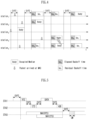
- STA3 may transmit the frame immediately after confirming that the medium is idle as much as DIFS. The remaining STAs monitor and wait for the medium to be occupied/busy. In the meantime, data to be transmitted may also occur in each of STA1, STA2, and STA5, and each STA waits as long as DIFS when the medium is monitored as idle, and then may perform a countdown of the backoff slot according to the random backoff count value selected by each STA. Assume that STA2 selects the smallest backoff count value and STA1 selects the largest backoff count value.
- STA1 and STA5 temporarily stop counting down and wait while STA2 occupies the medium.
- STA1 and STA5 wait for DIFS and resume the stopped backoff count. That is, frame transmission may be started after counting down the remaining backoff slots for the remaining backoff time. Since the remaining backoff time of STA5 is shorter than that of STA1, STA5 starts frame transmission. While STA2 occupies the medium, data to be transmitted may also occur in STA4.
- STA4 may wait for DIFS, and then may perform a countdown according to the random backoff count value selected by the STA4 and start transmitting frames.
- the example of FIG. 4 shows a case where the remaining backoff time of STA5 coincides with the random backoff count value of STA4 by chance. In this case, a collision may occur between STA4 and STA5. When a collision occurs, both STA4 and STA5 do not receive an ACK, so data transmission fails. In this case, STA4 and STA5 may double the CW value, select a random backoff count value, and perform a countdown.
- STA1 waits while the medium is occupied due to transmission of STA4 and STA5, waits for DIFS when the medium becomes idle, and then starts frame transmission after the remaining backoff time has elapsed.
- the data frame is a frame used for transmission of data forwarded to a higher layer, and may be transmitted after a backoff performed after DIFS elapses from when the medium becomes idle.
- the management frame is a frame used for exchange of management information that is not forwarded to a higher layer, and is transmitted after a backoff performed after an IFS such as DIFS or Point Coordination Function IFS (PIFS).
- IFS such as DIFS or Point Coordination Function IFS (PIFS).
- PIFS Point Coordination Function IFS
- a subtype frames of management frame there are a Beacon, an association request/response, a re-association request/response, a probe request/response, an authentication request/response, etc.
- a control frame is a frame used to control access to a medium.
- control frame As a subtype frames of control frame, there are Request-To-Send (RTS), Clear-To-Send (CTS), Acknowledgement (ACK), Power Save-Poll (PS-Poll), block ACK (BlockAck), block ACK request (BlockACKReq), null data packet announcement (NDP announcement), and trigger, etc.
- RTS Request-To-Send
- CTS Clear-To-Send
- ACK Acknowledgement
- PS-Poll Power Save-Poll
- BlockAck block ACK
- BlockACKReq block ACK request
- NDP announcement null data packet announcement
- a Quality of Service (QoS) STA may perform the backoff that is performed after an arbitration IFS (AIFS) for an access category (AC) to which the frame belongs, that is, AIFS[i] (where i is a value determined by AC), and then may transmit the frame.
- AIFS arbitration IFS
- AC access category
- the frame in which AIFS[i] can be used may be a data frame, a management frame, or a control frame other than a response frame.
- FIG. 5 is a diagram for explaining a frame transmission operation based on CSMA/CA to which the present disclosure may be applied.
- the CSMA/CA mechanism includes virtual carrier sensing in addition to physical carrier sensing in which a STA directly senses a medium.
- Virtual carrier sensing is intended to compensate for problems that may occur in medium access, such as a hidden node problem.
- the MAC of the STA may use a Network Allocation Vector (NAV).
- NAV Network Allocation Vector
- the NAV is a value indicating, to other STAs, the remaining time until the medium is available for use by an STA currently using or having the right to use the medium. Therefore, the value set as NAV corresponds to a period in which the medium is scheduled to be used by the STA transmitting the frame, and the STA receiving the NAV value is prohibited from accessing the medium during the corresponding period.
- the NAV may be configured based on the value of the "duration" field of the MAC header of the frame.
- a STA1 intends to transmit data to a STA2, and a STA3 is in a position capable of overhearing some or all of frames transmitted and received between the STA1 and the STA2.
- a mechanism using RTS/CTS frames may be applied.
- the medium is in an idle state. That is, the STA1 may correspond to a hidden node to the STA3.
- it may be determined that the carrier sensing result medium of the STA3 is in an idle state while transmission of the STA2 is being performed. That is, the STA2 may correspond to a hidden node to the STA3.
- a STA outside the transmission range of one of the STA1 or the STA2, or a STA outside the carrier sensing range for transmission from the STA1 or the STA3 may not attempt to occupy the channel during data transmission and reception between the STA1 and the STA2.
- the STA1 may determine whether a channel is being used through carrier sensing. In terms of physical carrier sensing, the STA1 may determine a channel occupation idle state based on an energy level or signal correlation detected in a channel. In addition, in terms of virtual carrier sensing, the STA1 may determine a channel occupancy state using a network allocation vector (NAV) timer.
- NAV network allocation vector
- the STA1 may transmit an RTS frame to the STA2 after performing a backoff when the channel is in an idle state during DIFS.
- the STA2 may transmit a CTS frame as a response to the RTS frame to the STA1 after SIFS.
- the STA3 may set a NAV timer for a frame transmission period (e.g., SIFS + CTS frame + SIFS + data frame + SIFS + ACK frame) that is continuously transmitted thereafter, using the duration information included in the RTS frame.
- a NAV timer for a frame transmission period (e.g., SIFS + data frame + SIFS + ACK frame) that is continuously transmitted thereafter, using the duration information included in the CTS frame.
- the STA3 may set the NAV accordingly.
- the STA3 may update the NAV timer using duration information included in the new frame. The STA3 does not attempt channel access until the NAV timer expires.
- the STA1 may transmit the data frame to the STA2 after SIFS from the time point when the reception of the CTS frame is completed.
- the STA2 may transmit an ACK frame as a response to the data frame to the STA1 after SIFS.
- the STA3 may determine whether the channel is being used through carrier sensing when the NAV timer expires. When the STA3 determines that the channel is not used by other terminals during DIFS after expiration of the NAV timer, the STA3 may attempt channel access after a contention window (CW) according to a random backoff has passed.
- CW contention window
- FIG. 6 is a diagram for explaining an example of a frame structure used in a WLAN system to which the present disclosure may be applied.
- the PHY layer may prepare a MAC PDU (MPDU) to be transmitted. For example, when a command requesting transmission start of the PHY layer is received from the MAC layer, the PHY layer switches to the transmission mode and configures information (e.g., data) provided from the MAC layer in the form of a frame and transmits it. In addition, when the PHY layer detects a valid preamble of the received frame, the PHY layer monitors the header of the preamble and sends a command notifying the start of reception of the PHY layer to the MAC layer.
- MPDU MAC PDU
- a PHY layer protocol data unit (PPDU) frame format is defined.
- a basic PPDU frame may include a Short Training Field (STF), a Long Training Field (LTF), a SIGNAL (SIG) field, and a Data field.
- STF Short Training Field
- LTF Long Training Field
- SIG SIGNAL
- Data field e.g., Data field
- the most basic (e.g., non-High Throughput (HT)) PPDU frame format may consist of only L-STF (Legacy-STF), L-LTF (Legacy-LTF), SIG field, and data field.
- PPDU frame format e.g., HT-mixed format PPDU, HT-greenfield format PPDU, VHT (Very High Throughput) PPDU, etc.
- STF, LTF, and SIG fields may be included between the SIG field and the data field (this will be described later with reference to FIG. 7 ) .
- the STF is a signal for signal detection, automatic gain control (AGC), diversity selection, precise time synchronization, and the like
- the LTF is a signal for channel estimation and frequency error estimation.
- the STF and LTF may be referred to as signals for synchronization and channel estimation of the OFDM physical layer.
- the SIG field may include a RATE field and a LENGTH field.
- the RATE field may include information on modulation and coding rates of data.
- the LENGTH field may include information on the length of data. Additionally, the SIG field may include a parity bit, a SIG TAIL bit, and the like.
- the data field may include a SERVICE field, a physical layer service data unit (PSDU), and a PPDU TAIL bit, and may also include padding bits if necessary.
- Some bits of the SERVICE field may be used for synchronization of the descrambler at the receiving end.
- the PSDU corresponds to the MAC PDU defined in the MAC layer, and may include data generated/used in the upper layer.
- the PPDU TAIL bit may be used to return the encoder to a 0 state.
- Padding bits may be used to adjust the length of a data field in a predetermined unit.
- a MAC PDU is defined according to various MAC frame formats, and a basic MAC frame consists of a MAC header, a frame body, and a Frame Check Sequence (FCS).
- the MAC frame may consist of MAC PDUs and be transmitted/received through the PSDU of the data part of the PPDU frame format.
- the MAC header includes a Frame Control field, a Duration/ID field, an Address field, and the like.
- the frame control field may include control information required for frame transmission/reception.
- the duration/ID field may be set to a time for transmitting a corresponding frame or the like.
- a null-data packet (NDP) frame format means a frame format that does not include a data packet. That is, the NDP frame refers to a frame format that includes a physical layer convergence procedure (PLCP) header part (i.e., STF, LTF, and SIG fields) in a general PPDU frame format and does not include the remaining parts (i.e., data field) .
- PLCP physical layer convergence procedure
- a NDP frame may also be referred to as a short frame format.
- FIG. 7 is a diagram illustrating examples of PPDUs defined in the IEEE 802.11 standard to which the present disclosure may be applied.
- the basic PPDU format (IEEE 802.11a/g) includes L-LTF, L-STF, L-SIG and Data fields.
- the basic PPDU format may also be referred to as a non-HT PPDU format.
- the HT PPDU format (IEEE 802.11n) additionally includes HT-SIG, HT-STF, and HT-LFT(s) fields to the basic PPDU format.
- the HT PPDU format shown in FIG. 7 may be referred to as an HT-mixed format.
- an HT-greenfield format PPDU may be defined, and this corresponds to a format consisting of HT-GF-STF, HT-LTF1, HT-SIG, one or more HT-LTF, and Data field, not including L-STF, L-LTF, and L-SIG (not shown).
- VHT PPDU format (IEEE 802.11ac) additionally includes VHT SIG-A, VHT-STF, VHT-LTF, and VHT-SIG-B fields to the basic PPDU format.
- HE PPDU format (IEEE 802.11ax) additionally includes Repeated L-SIG (RL-SIG), HE-SIG-A, HE-SIG-B, HE-STF, HE-LTF(s), Packet Extension (PE) field to the basic PPDU format.
- R-SIG Repeated L-SIG
- HE-SIG-A HE-SIG-B
- HE-STF HE-LTF(s)
- PE Packet Extension
- Some fields may be excluded or their length may vary according to detailed examples of the HE PPDU format.
- the HE-SIG-B field is included in the HE PPDU format for multi-user (MU), and the HE-SIG-B is not included in the HE PPDU format for single user (SU).
- SU single user
- the HE trigger-based (TB) PPDU format does not include the HE-SIG-B, and the length of the HE-STF field may vary to 8 us.
- the Extended Range (HE ER) SU PPDU format does not include the HE-SIG-B field, and the length of the HE-SIG-A field may vary to 16us.
- FIGs. 8 to 10 are diagrams for explaining examples of resource units of a WLAN system to which the present disclosure may be applied.
- the RU may include a plurality of subcarriers (or tones).
- the RU may be used when transmitting signals to multiple STAs based on the OFDMA scheme.
- the RU may be defined even when a signal is transmitted to one STA.
- the RU may be used for STF, LTF, data field of the PPDU, etc.
- RUs corresponding to different numbers of tones are used to construct some fields of 20 MHz, 40 MHz, or 80 MHz X-PPDUs (X is HE, EHT, etc.).
- X is HE, EHT, etc.
- resources may be allocated in RU units shown for the X-STF, X-LTF, and Data field.
- FIG. 8 is a diagram illustrating an exemplary allocation of resource units (RUs) used on a 20 MHz band.
- 26-units i.e., units corresponding to 26 tones
- 6 tones may be used as a guard band in the leftmost band of the 20 MHz band
- 5 tones may be used as a guard band in the rightmost band of the 20 MHz band.
- 7 DC tones are inserted in the center band, that is, the DC band
- 26-units corresponding to each of the 13 tones may exist on the left and right sides of the DC band.
- 26-unit, 52-unit, and 106-unit may be allocated to other bands. Each unit may be allocated for STAs or users.
- the RU allocation of FIG. 8 is utilized not only in a situation for multiple users (MU) but also in a situation for a single user (SU), and in this case, it is possible to use one 242-unit as shown at the bottom of FIG. 8 . In this case, three DC tones may be inserted.
- RUs of various sizes that is, 26-RU, 52-RU, 106-RU, 242-RU, etc. are exemplified, but the specific size of these RUs may be reduced or expanded. Therefore, in the present disclosure, the specific size of each RU (i.e., the number of corresponding tones) is exemplary and not restrictive. In addition, within a predetermined bandwidth (e.g., 20, 40, 80, 160, 320 MHz, ...) in the present disclosure, the number of RUs may vary according to the size of the RU. In the examples of FIG. 9 and/or FIG. 10 to be described below, the fact that the size and/or number of RUs may be varied is the same as the example of FIG. 8 .
- FIG. 9 is a diagram illustrating an exemplary allocation of resource units (RUs) used on a 40 MHz band.
- 26-RU, 52-RU, 106-RU, 242-RU, 484-RU, and the like may be used in the example of FIG. 9 as well.
- 5 DC tones may be inserted at the center frequency
- 12 tones may be used as a guard band in the leftmost band of the 40MHz band
- 11 tones may be used as a guard band in the rightmost band of the 40MHz band.
- a 484-RU when used for a single user, a 484-RU may be used.
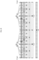
- FIG. 10 is a diagram illustrating an exemplary allocation of resource units (RUs) used on an 80 MHz band.
- 26-RU, 52-RU, 106-RU, 242-RU, 484-RU, 996-RU and the like may be used in the example of FIG. 10 as well.
- RU allocation of HE PPDUs and EHT PPDUs may be different, and the example of FIG. 10 shows an example of RU allocation for 80 MHz EHT PPDUs.
- HE PPDU 10 is the same in HE PPDU and EHT PPDU.
- EHT PPDU 23 DC tones are inserted into the DC band, and one 26-RU exists on the left and right sides of the DC band.
- one null subcarrier exists between 242-RUs rather than the center band, there are five null subcarriers in the EHT PPDU.
- one 484-RU does not include null subcarriers, but in the EHT PPDU, one 484-RU includes 5 null subcarriers.
- 996-RU when used for a single user, 996-RU may be used, and in this case, 5 DC tones are inserted in common with HE PPDU and EHT PPDU.
- EHT PPDUs over 160 MHz may be configured with a plurality of 80 MHz subblocks in FIG. 10 .
- the RU allocation for each 80 MHz subblock may be the same as that of the 80 MHz EHT PPDU of FIG. 10 . If the 80 MHz subblock of the 160 MHz or 320 MHz EHT PPDU is not punctured and the entire 80 MHz subblock is used as part of RU or multiple RU (MRU), the 80 MHz subblock may use 996-RU of FIG. 10 .
- the MRU corresponds to a group of subcarriers (or tones) composed of a plurality of RUs, and the plurality of RUs constituting the MRU may be RUs having the same size or RUs having different sizes.
- a single MRU may be defined as 52+26-tone, 106+26-tone, 484+242-tone, 996+484-tone, 996+484+242-tone, 2X996+484-tone, 3X996-tone, or 3X996+484-tone.
- the plurality of RUs constituting one MRU may correspond to small size (e.g., 26, 52, or 106) RUs or large size (e.g., 242, 484, or 996) RUs. That is, one MRU including a small size RU and a large size RU may not be configured/defined. In addition, a plurality of RUs constituting one MRU may or may not be consecutive in the frequency domain.
- the 80 MHz subblock may use RU allocation other than the 996-tone RU.
- the RU of the present disclosure may be used for uplink (UL) and/or downlink (DL) communication.
- the STA transmitting the trigger e.g., AP
- trigger information e.g., trigger frame or triggered response scheduling (TRS)
- the first STA may transmit a first trigger-based (TB) PPDU based on the first RU
- the second STA may transmit a second TB PPDU based on the second RU.
- the first/second TB PPDUs may be transmitted to the AP in the same time period.
- the STA transmitting the DL MU PPDU may allocate a first RU (e.g., 26/52/106/242-RU, etc.) to a first STA and allocate a second RU (e.g., 26/52/106/242-RU, etc.) to a second STA. That is, the transmitting STA (e.g., AP) may transmit the HE-STF, HE-LTF, and Data fields for the first STA through the first RU within one MU PPDU, and may transmit the HE-STF, HE-LTF, and Data fields for the second STA through the second RU.
- a first RU e.g., 26/52/106/242-RU, etc.
- a second RU e.g., 26/52/106/242-RU, etc.
- Information on the allocation of RUs may be signaled through HE-SIG-B in the HE PPDU format.
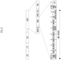
- FIG. 11 illustrates an example structure of a HE-SIG-B field.
- the HE-SIG-B field may include a common field and a user-specific field. If HE-SIG-B compression is applied (e.g., full-bandwidth MU-MIMO transmission), the common field may not be included in HE-SIG-B, and the HE-SIG-B content channel may include only a user-specific field. If HE-SIG-B compression is not applied, the common field may be included in HE-SIG-B.
- the common field may include information on RU allocation (e.g., RU assignment, RUs allocated for MU-MIMO, the number of MU-MIMO users (STAs), etc.)
- RU allocation e.g., RU assignment, RUs allocated for MU-MIMO, the number of MU-MIMO users (STAs), etc.
- the common field may include N*8 RU allocation subfields.
- One 8-bit RU allocation subfield may indicate the size (26, 52, 106, etc.) and frequency location (or RU index) of RUs included in the 20 MHz band.
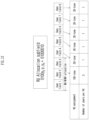
- a value of the 8-bit RU allocation subfield is 00000000, it may indicate that nine 26-RUs are sequentially allocated in order from the leftmost to the rightmost in the example of FIG. 8 , if the value is 00000001, it may indicate that seven 26-RUs and one 52-RU are sequentially allocated in order from leftmost to rightest, and if the value is 00000010, it may indicate that five 26-RUs, one 52-RU, and two 26-RUs are sequentially allocated from the leftmost side to the rightmost side.
- the value of the 8-bit RU allocation subfield is 01000y2yly0, it may indicate that one 106-RU and five 26-RUs are sequentially allocated from the leftmost to the rightmost in the example of FIG. 8 .
- multiple users/STAs may be allocated to the 106-RU in the MU-MIMO scheme.
- up to 8 users/STAs may be allocated to the 106-RU, and the number of users/STAs allocated to the 106-RU is determined based on 3-bit information (i.e., y2yly0). For example, when the 3-bit information (y2y1y0) corresponds to a decimal value N, the number of users/STAs allocated to the 106-RU may be N+1.
- one user/STA may be allocated to each of a plurality of RUs, and different users/STAs may be allocated to different RUs.
- a predetermined size e.g., 106, 242, 484, 996-tones, (7)
- a plurality of users/STAs may be allocated to one RU, and MU-MIMO scheme may be applied for the plurality of users/STAs.
- the set of user-specific fields includes information on how all users (STAs) of the corresponding PPDU decode their payloads.
- User-specific fields may contain zero or more user block fields.
- the non-final user block field includes two user fields (i.e., information to be used for decoding in two STAs).
- the final user block field contains one or two user fields.
- the number of user fields may be indicated by the RU allocation subfield of HE-SIG-B, the number of symbols of HE-SIG-B, or the MU-MIMO user field of HE-SIG-A.
- a User-specific field may be encoded separately from or independently of a common field.
- FIG. 12 is a diagram for explaining a MU-MIMO method in which a plurality of users/STAs are allocated to one RU.
- the user-specific field of HE-SIG-B may include 8 user fields (i.e., 4 user block fields). Eight user fields may be assigned to RUs as shown in FIG. 12 .
- the user field may be constructed based on two formats.
- the user field for a MU-MIMO allocation may be constructed with a first format
- the user field for non-MU-MIMO allocation may be constructed with a second format.
- user fields 1 to 3 may be based on the first format
- user fields 4 to 8 may be based on the second format.
- the first format and the second format may contain bit information of the same length (e.g., 21 bits).
- the user field of the first format (i.e., format for MU-MIMO allocation) may be constructed as follows. For example, out of all 21 bits of one user field, B0-B10 includes the user's identification information (e.g., STA-ID, AID, partial AID, etc.), B11-14 includes spatial configuration information such as the number of spatial streams for the corresponding user, B15-B18 includes Modulation and Coding Scheme (MCS) information applied to the Data field of the corresponding PPDU, B19 is defined as a reserved field, and B20 may include information on a coding type (e.g., binary convolutional coding (BCC) or low-density parity check (LDPC)) applied to the Data field of the corresponding PPDU.
- BCC binary convolutional coding
- LDPC low-density parity check
- the user field of the second format (i.e., the format for non-MU-MIMO allocation) may be constructed as follows. For example, out of all 21 bits of one user field, B0-B10 includes the user's identification information (e.g., STA-ID, AID, partial AID, etc.), B11-13 includes information on the number of spatial streams (NSTS) applied to the corresponding RU, B14 includes information indicating whether beamforming is performed (or whether a beamforming steering matrix is applied), B15-B18 includes Modulation and Coding Scheme (MCS) information applied to the Data field of the corresponding PPDU, B19 includes information indicating whether DCM (dual carrier modulation) is applied, and B20 may include information on a coding type (e.g., BCC or LDPC) applied to the Data field of the corresponding PPDU.
- B1-13 includes information on the number of spatial streams (NSTS) applied to the corresponding RU
- B14 includes information indicating whether beamforming is performed (or whether a beamforming steering matrix
- MCS MCS information
- MCS index MCS field, and the like used in the present disclosure may be indicated by a specific index value.
- MCS information may be indicated as index 0 to index 11.
- MCS information includes information on constellation modulation type (e.g., BPSK, QPSK, 16-QAM, 64-QAM, 256-QAM, 1024-QAM, etc.), and coding rate (e.g., 1/2, 2/ 3, 3/4, 5/6, etc.).
- coding rate e.g., 1/2, 2/ 3, 3/4, 5/6, etc.
- Information on a channel coding type e.g., BCC or LDPC
- BCC channel coding type
- FIG. 13 illustrates an example of a PPDU format to which the present disclosure may be applied.
- the PPDU of FIG. 13 may be referred as various names such as an EHT PPDU, a transmitted PPDU, a received PPDU, a first type or an Nth type PPDU.
- the PPDU or EHT PPDU of the present disclosure may be referred as various names such as a transmission PPDU, a reception PPDU, a first type or an Nth type PPDU.
- the EHT PPU may be used in an EHT system and/or a new wireless LAN system in which the EHT system is improved.
- the EHT MU PPDU of FIG. 13 corresponds to a PPDU carrying one or more data (or PSDUs) for one or more users. That is, the EHT MU PPDU may be used for both SU transmission and MU transmission.
- the EHT MU PPDU may correspond to a PPDU for one receiving STA or a plurality of receiving STAs.
- the EHT-SIG is omitted compared to the EHT MU PPDU.
- the STA may perform UL transmission based on the EHT TB PPDU format.
- L-STF to EHT-LTF correspond to a preamble or a physical preamble, and may be generated/transmitted/received/acquired/decoded in the physical layer.
- a Subcarrier frequency spacing of L-STF, L-LTF, L-SIG, RL-SIG, Universal SIGNAL (U-SIG), EHT-SIG field (these are referred to as pre-EHT modulated fields) may be set to 312.5 kHz.
- a subcarrier frequency spacing of the EHT-STF, EHT-LTF, Data, and PE field (these are referred to as EHT modulated fields) may be set to 78.125 kHz.
- the tone/subcarrier index of L-STF, L-LTF, L-SIG, RL-SIG, U-SIG, and EHT-SIG field may be indicated in units of 312.5 kHz
- the tone/subcarrier index of EHT-STF, EHT-LTF, Data, and PE field may be indicated in units of 78.125 kHz.
- the L-LTF and L-STF of FIG. 13 may be constructed identically to the corresponding fields of the PPDU described in FIGS. 6 to 7 .
- the L-SIG field of FIG. 13 may be constructed with 24 bits and may be used to communicate rate and length information.
- the L-SIG field includes a 4-bit Rate field, a 1-bit Reserved bit, a 12-bit Length field, a 1-bit Parity field, and a 6-bit Tail field may be included.
- the 12-bit Length field may include information on a time duration or a length of the PPDU.
- a value of the 12-bit Length field may be determined based on the type of PPDU. For example, for a non-HT, HT, VHT, or EHT PPDU, the value of the Length field may be determined as a multiple of 3. For example, for the HE PPDU, the value of the Length field may be determined as a multiple of 3 + 1 or a multiple of 3 + 2.
- the transmitting STA may apply BCC encoding based on a coding rate of 1/2 to 24-bit information of the L-SIG field. Thereafter, the transmitting STA may obtain 48-bit BCC coded bits. BPSK modulation may be applied to 48-bit coded bits to generate 48 BPSK symbols. The transmitting STA may map 48 BPSK symbols to any location except for a pilot subcarrier (e.g., ⁇ subcarrier index -21, -7, +7, +21 ⁇ ) and a DC subcarrier (e.g., ⁇ subcarrier index 0 ⁇ ) .
- a pilot subcarrier e.g., ⁇ subcarrier index -21, -7, +7, +21 ⁇
- DC subcarrier e.g., ⁇ subcarrier index 0 ⁇
- 48 BPSK symbols may be mapped to subcarrier indices -26 to -22, - 20 to -8, -6 to -1, +1 to +6, +8 to +20, and +22 to +26.
- the transmitting STA may additionally map the signals of ⁇ -1, -1, -1, 1 ⁇ to the subcarrier index ⁇ -28, -27, +27, +28 ⁇ .
- the above signal may be used for channel estimation in the frequency domain corresponding to ⁇ -28, -27, +27, +28 ⁇ .
- the transmitting STA may construct RL-SIG which is constructed identically to L-SIG.
- RL-SIG BPSK modulation is applied.
- the receiving STA may recognize that the received PPDU is a HE PPDU or an EHT PPDU based on the existence of the RL-SIG.
- U-SIG Universal SIG
- the U-SIG may be referred as various names such as a first SIG field, a first SIG, a first type SIG, a control signal, a control signal field, and a first (type) control signal, etc.
- the U-SIG may include N-bit information and may include information for identifying the type of EHT PPDU.
- U-SIG may be configured based on two symbols (e.g., two consecutive OFDM symbols).
- Each symbol (e.g., OFDM symbol) for the U-SIG may have a duration of 4us, and the U-SIG may have a total 8us duration.
- Each symbol of the U-SIG may be used to transmit 26 bit information.
- each symbol of the U-SIG may be transmitted and received based on 52 data tones and 4 pilot tones.
- a bit information (e.g., 52 un-coded bits) may be transmitted
- the first symbol of the U-SIG (e.g., U-SIG-1) may transmit the first X bit information (e.g., 26 un-coded bits) of the total A bit information
- the second symbol of the U-SIG (e.g., U-SIG-2) may transmit the remaining Y-bit information (e.g., 26 un-coded bits) of the total A-bit information.
- the transmitting STA may obtain 26 un-coded bits included in each U-SIG symbol.
- the transmitting STA may generate 52 BPSK symbols allocated to each U-SIG symbol by performing BPSK modulation on the interleaved 52-coded bits.
- One U-SIG symbol may be transmitted based on 56 tones (subcarriers) from subcarrier index -28 to subcarrier index +28, except for DC index 0.
- the 52 BPSK symbols generated by the transmitting STA may be transmitted based on the remaining tones (subcarriers) excluding pilot tones -21, -7, +7, and +21 tones.
- the A bit information (e.g., 52 un-coded bits) transmitted by the U-SIG includes a CRC field (e.g., a 4-bit field) and a tail field (e.g., 6 bit-length field).
- the CRC field and the tail field may be transmitted through the second symbol of the U-SIG.
- the CRC field may be constructed based on 26 bits allocated to the first symbol of U-SIG and 16 bits remaining except for the CRC/tail field in the second symbol, and may be constructed based on a conventional CRC calculation algorithm.
- the tail field may be used to terminate the trellis of the convolution decoder, and for example, the tail field may be set to 0.
- a bit information (e.g., 52 un-coded bits) transmitted by the U-SIG (or U-SIG field) may be divided into version-independent bits and version-independent bits.
- a size of the version-independent bits may be fixed or variable.
- the version-independent bits may be allocated only to the first symbol of U-SIG, or the version-independent bits may be allocated to both the first symbol and the second symbol of U-SIG.
- the version-independent bits and the version-dependent bits may be referred as various names such as a first control bit and a second control bit, etc.
- the version-independent bits of the U-SIG may include a 3-bit physical layer version identifier (PHY version identifier).
- the 3-bit PHY version identifier may include information related to the PHY version of the transmitted/received PPDU.
- the first value of the 3-bit PHY version identifier may indicate that the transmission/reception PPDU is an EHT PPDU.
- the transmitting STA may set the 3-bit PHY version identifier to a first value.
- the receiving STA may determine that the received PPDU is an EHT PPDU based on the PHY version identifier having the first value.
- the version-independent bits of U-SIG may include a 1-bit UL/DL flag field.
- a first value of the 1-bit UL/DL flag field is related to UL communication, and a second value of the UL/DL flag field is related to DL communication.
- the version-independent bits of the U-SIG may include information on the length of a transmission opportunity (TXOP) and information on a BSS color ID.
- TXOP transmission opportunity
- EHT PPDU related to SU mode e.g., EHT PPDU related to MU mode
- EHT PPDU related to TB mode e.g., EHT PPDU related to Extended Range transmission, etc.
- information on the type of EHT PPDU may be included in the version-dependent bits of the U-SIG.
- the U-SIG may include information on 1) a bandwidth field containing information on a bandwidth, 2) a field containing information on a MCS scheme applied to EHT-SIG, 3) an indication field containing information related to whether the DCM technique is applied to the EHT-SIG, 4) a field containing information on the number of symbols used for EHT-SIG, 5) a field containing information on whether EHT-SIG is constructed over all bands, 6) a field containing information on the type of EHT-LTF/STF, and 7) a field indicating the length of EHT-LTF and CP length.
- Preamble puncturing may be applied to the PPDU of FIG. 13 .
- Preamble puncturing may mean transmission of a PPDU for which no signal is present in one or more 20 MHz subchannels among the bandwidth of the PPDU.
- Preamble puncturing may be applied to a PPDU transmitted to one or more users.
- the resolution of preamble puncturing may be 20 MHz for EHT MU PPDUs in OFDMA transmissions with bandwidths greater than 40 MHz and non-OFDMA transmissions with 80 MHz and 160 MHz bandwidths. That is, in the above case, puncturing on a subchannel smaller than 242-tone RU may not be allowed.
- the resolution of preamble puncturing may be 40 MHz. That is, puncturing for a subchannel smaller than 484-tone RU in a 320 MHz bandwidth may not be allowed. In addition, preamble puncturing may not be applied to the primary 20 MHz channel in the EHT MU PPDU.
- information on preamble puncturing may be included in the U-SIG and/or the EHT-SIG.
- the first field of the U-SIG may include information on the contiguous bandwidth of the PPDU
- the second field of the U-SIG may include information on preamble puncturing applied to the PPDU.
- the U-SIG and the EHT-SIG may include information on preamble puncturing based on the following method. If the bandwidth of the PPDU exceeds 80 MHz, the U-SIG may be individually constructed in units of 80 MHz. For example, if the bandwidth of the PPDU is 160 MHz, the PPDU may include a first U-SIG for a first 80 MHz band and a second U-SIG for a second 80 MHz band. In this case, the first field of the first U-SIG includes information on the 160 MHz bandwidth, and the second field of the first U-SIG includes information on preamble puncturing applied to the first 80 MHz band (i.e., information on a preamble puncturing pattern).
- the first field of the second U-SIG includes information on a 160 MHz bandwidth
- the second field of the second U-SIG includes information on preamble puncturing applied to a second 80 MHz band (i.e., information on a preamble puncturing pattern).
- the EHT-SIG following the first U-SIG may include information on preamble puncturing applied to the second 80 MHz band (i.e., information on a preamble puncturing pattern)
- the EHT-SIG following the second U-SIG may include information on preamble puncturing applied to the first 80 MHz band (i.e., information on a preamble puncturing pattern).
- the U-SIG and the EHT-SIG may include information on preamble puncturing based on the following method.
- the U-SIG may include information on preamble puncturing for all bands (i.e., information on a preamble puncturing pattern). That is, EHT-SIG does not include information on preamble puncturing, and only U-SIG may include information on preamble puncturing (i.e., information on a preamble puncturing pattern).
- U-SIG may be constructed in units of 20 MHz. For example, if an 80 MHz PPDU is constructed, the U-SIG may be duplicated. That is, the same 4 U-SIGs may be included in the 80 MHz PPDU. PPDUs exceeding 80 MHz bandwidth may include different U-SIGs.
- the EHT-SIG of FIG. 13 may include control information for the receiving STA.
- EHT-SIG may be transmitted through at least one symbol, and one symbol may have a length of 4us.
- Information on the number of symbols used for EHT-SIG may be included in U-SIG.
- the EHT-SIG may include technical features of HE-SIG-B described through FIGS. 11 and 12 .
- EHT-SIG like the example of FIG. 8 , may include a common field and a user-specific field.
- the Common field of the EHT-SIG may be omitted, and the number of user-specific fields may be determined based on the number of users.
- the common field of the EHT-SIG and the user-specific field of the EHT-SIG may be coded separately.
- One user block field included in the user-specific field may contain information for two user fields, but the last user block field included in the user-specific field may contain one or two user fields. That is, one user block field of the EHT-SIG may contain up to two user fields.
- each user field may be related to MU-MIMO allocation or non-MU-MIMO allocation.
- the common field of the EHT-SIG may include a CRC bit and a Tail bit
- the length of the CRC bit may be determined as 4 bits
- the length of the tail bit is determined by 6 bits and may be set to 000000.
- the common field of the EHT-SIG may include RU allocation information.
- RU allocation information may mean information on the location of an RU to which a plurality of users (i.e., a plurality of receiving STAs) are allocated.
- RU allocation information may be configured in units of 9 bits (or N bits).
- a mode in which a common field of EHT-SIG is omitted may be supported.
- the mode in which the common field of the EHT-SIG is omitted may be referred as a compressed mode.
- a plurality of users (i.e., a plurality of receiving STAs) of the EHT PPDU may decode the PPDU (e.g., the data field of the PPDU) based on non-OFDMA. That is, a plurality of users of the EHT PPDU may decode a PPDU (e.g., a data field of the PPDU) received through the same frequency band.
- multiple users of the EHT PPDU may decode the PPDU (e.g., the data field of the PPDU) based on OFDMA. That is, a plurality of users of the EHT PPDU may receive the PPDU (e.g., the data field of the PPDU) through different frequency bands.
- EHT-SIG may be constructed based on various MCS scheme. As described above, information related to the MCS scheme applied to the EHT-SIG may be included in the U-SIG.
- the EHT-SIG may be constructed based on the DCM scheme.
- the DCM scheme may reuse the same signal on two subcarriers to provide an effect similar to frequency diversity, reduce interference, and improve coverage. For example, modulation symbols to which the same modulation scheme is applied may be repeatedly mapped on available tones/subcarriers.
- modulation symbols e.g., BPSK modulation symbols
- first contiguous half tones e.g., 1st to 26th tones
- modulation symbols e.g., BPSK modulation symbols
- the remaining contiguous half tones e.g., 27th to 52nd tones. That is, a modulation symbol mapped to the 1st tone and a modulation symbol mapped to the 27th tone are the same.
- the EHT-STF of FIG. 13 may be used to enhance automatic gain control (AGC) estimation in a MIMO environment or an OFDMA environment.
- the EHT-LTF of FIG. 13 may be used to estimate a channel in a MIMO environment or an OFDMA environment.
- Information on the type of STF and/or LTF may be included in the U-SIG field and/or the EHT-SIG field of FIG. 13 .
- GI guard interval
- the PPDU (i.e., EHT PPDU) of FIG. 13 may be constructed based on an example of RU allocation of FIGS. 8 to 10 .
- a EHT PPDU transmitted on a 20 MHz band may be constructed based on the RU of FIG. 8 . That is, a RU location of EHT-STF, EHT-LTF, and data field included in the EHT PPDU may be determined as shown in FIG. 8 .
- a EHT PPDU transmitted on a 40 MHz band that is, a 40 MHz EHT PPDU may be constructed based on the RU of FIG. 9 . That is, a RU location of EHT-STF, EHT-LTF, and data field included in the EHT PPDU may be determined as shown in FIG. 9 .
- the EHT PPDU transmitted on the 80 MHz band may be constructed based on the RU of FIG. 10 . That is, a RU location of EHT-STF, EHT-LTF, and data field included in the EHT PPDU may be determined as shown in FIG. 10 .
- the tone-plan for 80 MHz in FIG. 10 may correspond to two repetitions of the tone-plan for 40 MHz in FIG. 9 .
- the tone-plan for 160/240/320 MHz may be configured in the form of repeating the pattern of FIG. 9 or 10 several times.
- the PPDU of FIG. 13 may be identified as an EHT PPDU based on the following method.
- the receiving STA may determine the type of the received PPDU as the EHT PPDU based on the following. For example, when 1) the first symbol after the L-LTF signal of the received PPDU is BPSK, 2) RL-SIG in which the L-SIG of the received PPDU is repeated is detected, and 3) the result of applying the modulo 3 calculation to the value of the Length field of the L-SIG of the received PPDU (i.e., the remainder after dividing by 3) is detected as 0, the received PPDU may be determined as a EHT PPDU.
- the receiving STA may determine the type of the EHT PPDU based on bit information included in symbols subsequent to the RL-SIG of FIG. 13 . In other words, the receiving STA may determine the received PPDU as a EHT PPDU, based on 1) the first symbol after the L-LTF signal, which is BSPK, 2) RL-SIG contiguous to the L-SIG field and identical to the L-SIG, and 3) L-SIG including a Length field in which the result of applying modulo 3 is set to 0.
- the receiving STA may determine the type of the received PPDU as the HE PPDU based on the following. For example, when 1) the first symbol after the L-LTF signal is BPSK, 2) RL-SIG in which L-SIG is repeated is detected, and 3) the result of applying modulo 3 to the length value of L-SIG is detected as 1 or 2, the received PPDU may be determined as a HE PPDU.
- the receiving STA may determine the type of the received PPDU as non-HT, HT, and VHT PPDU based on the following. For example, when 1) the first symbol after the L-LTF signal is BPSK and 2) RL-SIG in which L-SIG is repeated is not detected, the received PPDU may be determined as non-HT, HT, and VHT PPDU.
- the receiving STA when the receiving STA detects an RL-SIG in which the L-SIG is repeated in the received PPDU, it may be determined that the received PPDU is a HE PPDU or an EHT PPDU. In this case, if the rate (6Mbps) check fails, the received PPDU may be determined as a non-HT, HT, or VHT PPDU. If the rate (6Mbps) check and parity check pass, when the result of applying modulo 3 to the Length value of L-SIG is detected as 0, the received PPDU may be determined as an EHT PPDU, and when the result of Length mod 3 is not 0, it may be determined as a HE PPDU.
- the PPDU of FIG. 13 may be used to transmit and receive various types of frames.
- the PPDU of FIG. 13 may be used for (simultaneous) transmission and reception of one or more of a control frame, a management frame, or a data frame.
- the U-SIG content is the same in both 20 MHz subchannels.
- the U-SIG content is the same in all non-punctured 20 MHz subchannels.
- the U-SIG content is the same on all non-punctured 20 MHz subchannels within each 80 MHz subblock and may be different from the U-SIG content in other 80 MHz subblocks.
- the U-SIG-1 part of the U-SIG of the EHT MU PPDU may include PHY version identifier (B0-B2), BW (B3-B5), UL/DL (B6), BSS color (B7-B12), and TXOP (B13-B19), and U-SIG-2 part may include PPDU type and compression mode (B0-B1), validate (B2), punctured channel information (B3-B7), validate (B8), EHT-SIG MCS (B9-B10), number of EHT-SIG symbols (B11-B15), CRC (B16-B19), and tail (B20-B25).
- 1 denotes a non-punctured subchannel
- x denotes a punctured subchannel.
- the puncturing granularity for the 80 MHz and 160 MHz PPDU bandwidths may be 20 MHz
- the puncturing granularity for the 320 MHz PPDU bandwidth may be 40 MHz.
- the U-SIG-1 part of the U-SIG of the EHT TB PPDU may include a version identifier (B0-B2), BW (B3-B5), UL/DL (B6), BSS color (B7-B12), TXOP (B13-B19), and disregard (B20-B25), and U-SIG-2 part may include PPDU type and compression mode (B0-B1), validate (B2), spatial reuse 1 (B3-B6), spatial reuse 2 (B7-B10), disregard (B11-B15), CRC (B16-B19), and tail (B20-B25).
- the U-SIG field of the EHT MU PPDU includes 5-bit punctured channel information, but the EHT TB PPDU does not include punctured channel information. This is because it is assumed that the EHT TB PPDU is constructed according to resource allocation indicated by the trigger frame or TRS control information, so the STA does not need to inform the AP of the resource information of the EHT TB PPDU.
- the STA may not respond with the HE TB PPDU. For example, if, in the non-AP STA, a common information field included in the trigger frame or one or more subfields of an user field addressed to the non-AP STA or selected by the non-AP STA are not recognized, supported, or have an unsatisfied value, the corresponding non-AP STA may choose not to respond to the trigger frame.
- the corresponding non-AP STA may choose not to respond to the TRS control subfield.
- a sounding procedure/protocol is used to determine channel state information.
- a beamformer STA requesting channel state information may transmit a training signal to beamformee STA(s).
- the beamformee STA may measure a channel using the training signal (e.g., sounding NDP) and feedback an estimate of a channel state to the beamformer STA.
- the beamformer STA may derive a steering matrix or a beamforming matrix using the feedback estimation.
- the beamforming STA may feedback estimation of the channel state to the beamformer STA through a compressed beamforming/channel quality indication (CQI) report frame.
- Feedback information may include single user (SU) feedback, multi-user (MU) feedback, CQI feedback, and the like.
- the beamformer STA may transmit an NDP announcement and NDP to the beamformee(s), and may receive feedback information from the beamformee STA(s). Additionally or alternatively, the beamformer STA may transmit the NDP announcement and the NDP to the beamformer(s), and may receive feedback information from the beamformer(s) by transmitting a beamforming report poll (BFRP) or a BFRP trigger to the beamformer(s).
- BFRP beamforming report poll
- BFRP beamforming report poll
- An NDP Announcement (NDPA) frame may have multiple types/variants.
- the NDP announcement frame may be configured in various formats such as a VHT NDP announcement frame, a HE NDP announcement frame, and an EHT NDP announcement frame, and the like. These formats may be distinguished by the NDP Announcement Variant subfield within the sounding dialog token field.
- FIG. 14 illustrates an exemplary format of an NDP announcement frame to which the present disclosure may be applied.
- the NDP announcement frame may include one or more STA Info fields.
- a receiver address (RA) field may be set to an address of an STA capable of providing feedback.
- the RA field may be set to a broadcast address.
- a transmitter address (TA) field may be set to an address of an STA transmitting an NDP announcement frame or may be set to a bandwidth signaling TA (bandwidth signaling TA) of an STA transmitting an NDP announcement frame.
- TA bandwidth signaling TA
- the TA field may be set to bandwidth signaling TA.
- the first two bits (B0 and B1) of the eight bits (B0-B7) of the sounding dialog token field may be used to indicate the type/variant of the NDP announcement frame.
- the VHT NDP announcement frame may be indicated if B0 has a value of 0 and the value of B1 is 0, and the HE NDP announcement frame may be indicated if B0 has a value of 0 and the value of B1 is 1.
- the EHT NDP notification frame may correspond to a case where both values of B0 and B1 are set to 1. If the value of B0 is 1 and the value of B1 is 0, this may correspond to a ranging NDP announcement frame.
- VHT STA since the first two bits (B0 and B1) of the sounding dialog token field are defined as reserved, the VHT STA may recognize the sounding dialog token number field of bits B2-B7 regardless of the values of B0 and B1.
- the VHT STA may recognize the sounding dialog token number field of bits B2-B7 regardless of the values of B0 and B1.
- the first 1-bit (B0) of the Sounding Dialog Token field is defined as reserved, setting the value of the second bit (B1) to 0 is defined as indicating a VHT NDP announcement frame, and setting the value of the second bit (B1) to 1 is defined as indicating a HE NDP announcement frame. Accordingly, the HE STA may recognize the sounding dialog token number field of bits B2-B7 when the value of B1 is 1 regardless of the value of B0.
- the sounding dialog token number subfield may include a value for identifying an NDP announcement frame selected by the beamformer.
- the NDP announcement frame may include n (n is an integer greater than or equal to 1) STA Info fields.
- the STA Info field of the VHT NDP announcement frame may include AID12, feedback type, and Nc index subfields.
- the AID12 subfield contains 12 least significant bits (LSBs) among the AIDs of STAs expected to process subsequent NDP(s) and prepare for sounding feedback.
- LSBs least significant bits
- the feedback type subfield indicates the type of feedback requested, and corresponds to SU when the value is 0 and MU when the value is 1.
- the Nc index subfield indicates a value obtained by subtracting 1 from the number of columns (i.e., Nc) in the compressed beamforming feedback matrix (i.e., Nc-1) when the feedback type is MU. In case of SU, the Nc index field is reserved.
- FIG. 14 (b) illustrates the format of the STA Info field of the HE NDP announcement frame when the value of the AID11 field is not a specific value (e.g., 2047).
- a value of the AID11 subfield other than the specific value includes 11 LSBs among AIDs of STAs expected to process subsequent NDP(s) and prepare for sounding feedback.
- the partial BW Info subfield may contain 7-bit RU start index (B0-B6) and 7-bit RU end index (B7-B13).
- the RU index may be determined according to the bandwidth of the NDP announcement frame, and its unit may be 26-tone RU.
- the value of the RU start/end index subfield may be set to X-1.
- the feedback type and Ng subfield and codebook size subfield may indicate SU or CQI.
- Setting disambiguation subfield to 1 may prevent a non-HE STA (e.g., VHT STA) from wrongly identifying the corresponding field as an AID field.
- VHT STA non-HE STA
- the Nc subfield is set to a value of Nc-1.
- Nc corresponds to the number of columns in the compressed beamforming feedback matrix
- Nc may correspond to the number of space-time streams (STS).
- STS space-time streams
- the Nc subfield may be reserved.
- FIG. 14(c) illustrates the format of the STA Info field of the HE NDP announcement frame when the value of the AID11 field is a specific value (e.g., 2047).
- the disallowed subchannel bitmap subfield indicates the 20 MHz subchannels and the 242-tone RUs that are present in sounding NDPs announced by the NDP Announcement frame and the 242-tone RUs that are to be included in requested sounding feedback.
- the lowest numbered bit of the disallowed Subchannel bitmap corresponds to a 20MHz subchannel that lies at the lowest frequency among all 20MHz subchannels within the BSS bandwidth. Each successive bit in the bitmap corresponds to the next higher 20 MHz subchannel.
- a bit in the bitmap is set to 1 may indicate that no energy is present in the sounding NDP associated with this NDP Announcement frame.
- the 242-tone RU that is most closely aligned in frequency with the 20 MHz subchannel may be disallowed for PPDUs that use a specific tone plan.
- STAs addressed by the NDP Announcement frame do not include tones from disallowed 242-tone RUs when determining the average SNR of STS 1 to Nc and when generating requested sounding feedback. If a 20 MHz subchannel and its corresponding 242-tone RU is allowed, the corresponding bit in the bitmap is set to 0.
- FIG. 14 (d) illustrates the format of the STA Info field of the EHT NDP announcement frame.
- the AID11 subfield may be defined as shown in Table 2. Basically, the AID11 subfield includes the identifier of the STA expected to process the subsequent NDP and prepare for sounding feedback.
- Table 2 AID Subfield value Description NDP Announcement frame variant applicability 0 - STA Info field is addressed to the associated AP or mesh AP or IBSS STA Applicable for all variant 1-2007 - STA Info field is addressed to an associated STA whose AID is equal to the value in the AID11 subfield if the NDP Announcement frame is not a Ranging variant.
- Applicable for all variant - STA Info field is addressed to an unassociated STA or an associated STA whose RSID/AID is equal to the value in the RSID11/AID11 subfield if the NDP Announcement frame is a Ranging variant - 2007 value is reserved for EHT variant. 2008-2042 reserved Not applicable for all variant 2043 - STA Info field contains a Sequence Authentication Code subfield if the NDP Announcement frame is a Ranging variant. - Otherwise, AID11 value is reserved. Applicable only for Ranging variant 2044 - STA Info field contains a partial timing synchronization function (TSF) if the NDP Announcement frame is a Ranging variant. - Otherwise, AID11 value is reserved.
- TSF timing synchronization function
- Ranging variant 2045 - STA Info field contains ranging measurement parameters if the NDP Announcement frame is a Ranging variant. - Otherwise, AID11 value is reserved. Applicable only for Ranging variant 2046 reserved Not applicable for all variant 2047 - STA Info field contains a Disallowed Subchannel Bitmap if the NDP Announcement frame is a HE variant. - Otherwise, AID11 value is reserved. Applicable only for HE variant
- the partial BW subfield may include a 1-bit (B0) resolution subfield and an 8-bit (B1-B8) feedback bitmap.
- the resolution subfield indicates the resolution bandwidth (e.g., 20 MHz or 40 MHz) for each bit of the feedback bitmap subfield.
- the feedback bitmap subfield may indicate a request for each resolution bandwidth from a low frequency to a high frequency, and the first bit (B1) of the bitmap corresponds to the lowest resolution bandwidth.
- Each bit of the feedback bitmap is set to 1 when feedback for the corresponding resolution bandwidth is requested. If the bandwidth of the EHT NDP announcement frame is less than 320 MHz, a resolution of 20 MHz may be indicated by setting the value of the resolution bit (B0) to 0.
- B1 is set to 1 to indicate that feedback for the 242-tone RU is requested, and B2-B8 may be reserved and set to 0.
- B1 and B2 indicate that feedback is requested in each of the two 242-tone RUs from low to high frequencies, and B3-B8 may be reserved and set to 0.
- B0 When the bandwidth of the PPDU carrying the EHT NDP announcement frame is 80 MHz, B0 may be set to 0 to indicate a resolution of 20 MHz. If all of B1-B4 are set to 1, it may indicate that feedback for a 996-tone RU is requested. Otherwise, B1-B4 may indicate that feedback in each of the four 242-tone RUs from low to high frequencies is requested, and B5-B8 may be reserved and set to 0.
- B0 When the bandwidth of the PPDU carrying the EHT NDP announcement frame is 160 MHz, B0 may be set to 0 to indicate a resolution of 20 MHz. If all B1-B4 are set to 1, it may indicate that feedback for the lower 996-tone RU is requested, otherwise B1-B4 may indicate that feedback is requested in each of four 242-tone RUs from a low frequency to a high frequency in the lower 80 MHz. If all B5-B8 are set to 1, it may indicate that feedback for the upper 996-tone RU is requested, otherwise B5-B8 may indicate that feedback is requested in each of four 242-tone RUs from low to high frequencies in the upper 80 MHz.
- B0 When the bandwidth of the PPDU carrying the EHT NDP announcement frame is 320 MHz, B0 may be set to 1 to indicate a resolution of 40 MHz. When both B1 and B2 are set to 1, it may indicate that feedback for the first 996-tone RU is requested, otherwise, B1 and B2 may indicate that feedback is requested in each of the two 484-tone RUs from a low frequency to a high frequency in the first 80 MHz. When both B3 and B4 are set to 1, it may indicate that feedback for the second 996-tone RU is requested, otherwise, B3 and B4 may indicate that feedback is requested in each of the two 484-tone RUs from the low frequency to the high frequency in the second 80 MHz.
- both B5 and B6 When both B5 and B6 are set to 1, it may indicate that feedback for the third 996-tone RU is requested, otherwise, B5 and B6 may indicate that feedback is requested in each of the two 484-tone RUs from the low frequency to the high frequency in the third 80 MHz.
- both B7 and B8 When both B7 and B8 are set to 1, it may indicate that feedback for the fourth 996-tone RU is requested, otherwise, B7 and B8 may indicate that feedback is requested in each of the two 484-tone RUs from the low frequency to the high frequency in the fourth 80 MHz.
- the feedback tone set for each 484-tone RU may consist of two 242-tone RU overlapping feedback tone sets with the 484-tone RU.
- the partial BW subfield may have the same value as in the example of Table 3 according to a related configuration.
- the feedback type and Ng subfield and the codebook size subfields may be set according to the example shown in Table 4.
- the feedback type and Ng subfield and the codebook size subfields may be set according to the example shown in Table 5.
- Table 5 Feedback Type And Ng Codebook Size Description B25 B26 B28 0 Reserved Reserved SU 1 1 0 CQI
- Setting disambiguation subfield to 1 may prevent a non-EHT STA (e.g., VHT STA) from wrongly identifying the corresponding field as an AID field.
- VHT STA non-EHT STA
- RA is set to a broadcast address, and the following may be applied. If the feedback type and Ng subfield and the codebook size subfield indicate SU or MU, Nc index subfield is set to a value of Nc-1, Nc corresponds to the number of columns in the compressed beamforming feedback matrix, and values greater than 7 are reserved in the Nc index subfield. If the feedback type and Ng subfield and the codebook size subfield indicate CQI, Nc index subfield is set to a value of Nc-1, Nc corresponds to the number of space-time streams (STS), and values greater than 7 are reserved in the Nc index subfield.
- One or more STA Info fields may exist.
- the RA field may be set to an individual address, and the Nc index subfield may be reserved.
- HE non-trigger based (non-TB) sounding sequence is initiated by the HE beamformer with an individually addressed HE NDP announcement frame including one STA information field, and after SIFS, the HE sounding NDP may be transmitted to the (single) HE beamformer.
- the HE beamformer may receive the HE sounding NDP from the HE beamformer and, after SIFS, respond by transmitting a HE compressed beamforming/CQI frame to the HE beamformer.
- the HE beamformer that starts the HE non-TB sounding sequence may transmit a HE NDP announcement frame with a single STA information (Info) field, and if the STA identified by the RA field is a mesh STA, AP, or IBSS member STA, the value of the AID11 field in the corresponding STA information field may be set to 0 or the AID of the STA identified by the RA field rather than 2047.
- the HE beamformer may initiate a HE non-TB sounding sequence with the HE beamformer to request SU feedback across the entire bandwidth.
- the HE beamformer may not start HE non-TB with a HE NDP announcement frame with a partial BW information subfield indicating less than the full bandwidth.
- the HE TB sounding sequence may be started by a HE beamformer, a HE sounding NDP after SIFS, and a BFRP trigger frame after SIFS using a broadcast HE NDP announcement frame with two or more STA information fields.
- One or more HE beamformers may receive a BFPR trigger frame and, after SIFS, respond with a HE compressed beamforming/CQI frame.
- the BFRQ trigger frame may include one or more user information fields that identify the HE beamformer.
- the HE beamformer that starts the HE TB sounding sequence may transmit a HE NDP announcement frame that includes two or more STA information fields and an RA field set as a broadcast address.
- the HE beamformer may initiate a HE TB sounding sequence to request MU feedback across the entire bandwidth.
- the HE beamformer may initiate a HE TB sounding sequence to request a feedback variant only if the feedback variant is calculated based on parameters supported by the HE beamformer. Otherwise, the HE beamformer may not request a feedback variant calculated based on parameters that the HE beamformer does not support.
- HE beamformer that transmits the HE NDP announcement frame to the HE beamformer that is an AP, TDLS peer STA, mesh STA, or IBSS STA may include one STA information (info) field in the HE NDP announcement frame and set the AID11 field to 0 in the STA information field of the frame.
- info STA information
- a HE beamformer that is an AP and transmits a HE NDP announcement frame to one or more HE beamformers may set the AID11 field of the STA information field identifying the non-AP STA to 11 LSB of the AID of the non-AP STA.
- the HE NDP announcement frame may not include multiple STA information fields with the same value in the AID11 subfield.
- the HE beamformer transmitting the HE NDP announcement frame that starts the HE TB sounding sequence may include an STA information field with an AID11 subfield value of 2047 to indicate a disallowed subchannel during punctured channel operation. If the STA information field is present, the STA information field with an AID11 value of 2047 may be the first STA information field of the frame.
- the HE beamformer transmitting the HE NDP announcement frame may not include one or more STA information fields with an AID11 subfield value of 2047.
- the HE beamformer that started the HE TB sounding sequence may transmit another BFRP trigger frame in the same TXOP.
- the HE beamformer may use an additional BFRP trigger frame to request HE compressed beamforming/CQI reporting that was not processed in the previous BFRP trigger frame or to request retransmission of the HE compressed beamforming/CQI report.
- the HE beamformer may not transmit a BFRP trigger frame identifying the STA identified in the HE NDP Announcement frame of the HE TB sounding sequence unless it is in the same TXOP as the HE TB sounding sequence.
- STA information field in HE NDP announcement frame requesting SU or MU feedback may indicate the subcarrier grouping (Ng), codebook size, and number of columns (Nc) to be used by the HE beamformer identified by the STA information field for generation of SU or MU feedback.
- Ng subcarrier grouping
- Nc number of columns
- the EHT sounding protocol may be defined/configured similarly/same as the HE sounding protocol, except for the size of the partial BW information subfield and/or Nc subfield on the NDP announcement frame.
- the partial information subfield and Nc subfield on the STA information field included in the HE NDP announcement frame may be composed of 14 bits and 3 bits, respectively
- the partial information subfield and Nc index subfield on the STA information field included in the EHT NDP announcement frame may be composed of 9 bits and 4 bits, respectively.
- EHT non-trigger based (non-TB) sounding sequence is initiated by an EHT beamformer with an individually addressed EHT NDP announcement frame including one STA information field, and after SIFS, the EHT sounding NDP may be transmitted to the (single) EHT beamformer.
- the EHT TB sounding sequence may be started by an EHT beamformer, an EHT sounding NDP after SIFS, and a BFRP trigger frame after SIFS using a broadcast EHT NDP announcement frame with two or more STA information fields.
- One or more HE beamformers may receive a BFPR trigger frame and, after SIFS, respond with an EHT compressed beamforming/CQI frame.
- the BFRQ trigger frame may include one or more user information (user info) fields that identify the EHT beamformer.
- A-PPDU Aggregated-physical layer protocol data unit
- An aggregated-PPDU may correspond to a new format in which a plurality of PPDU formats are aggregated in the frequency domain.
- A-PPDU transmission a first PPDU format may be transmitted in a first frequency band and a second PPDU format may be transmitted in a second frequency band.
- the first frequency band and the second frequency band may be included in the A-PPDU band and may not overlap each other.
- PPDU formats to be aggregated may include EHT format and HE format, but other PPDU formats may also be aggregated.
- TB PPDUs being aggregated may include not only a case where an EHT format TB PPDU and a HE format TB PPDU are aggregated, but also a case where an EHT format TB PPDU and a new format (hereinafter referred to as "EHT+") TB PPDU after EHT are aggregated.
- EHT+ new format
- the PPDU bandwidth may be set to a specific bandwidth.
- the number of merged PPDU formats may be 2 or more.
- STAs supporting different PPDU formats (or different versions/types) in one OFDMA transmission may be multiplexed using a frequency domain A-PPDU.
- Various versions/types supported by STAs may include HE and EHT, but may further include a EHT+ and a version/type before HE (e.g., VHT, etc.).
- Bandwidths allocated to different STAs may be the same or different, and combinations of various bandwidths may be determined.
- NDP Announcement (NDPA) frame described with reference to FIG. 14 and the sounding procedure and protocol described with reference to FIG. 15 were defined for sounding purposes for transmitting and receiving PPDUs in a single format.
- A-PPDU aggregated-PPDU
- NDP announcement frame NDP announcement frame
- trigger frame a sounding protocol suitable for the sounding procedure to support the aggregated-PPDU (A-PPDU) structure including multiple (different) PPDU formats and the structure of NDP, NDP announcement frame, and trigger frame.
- A-PPDU aggregated-PPDU
- NDP announcement frame NDP announcement frame
- trigger frame a sounding procedure based on a new NDP that can support A-PPDU, a new NDP announcement frame format, and a new trigger frame.
- the first PPDU format is applied in the first frequency unit (it can be replaced with the first band or first frequency band, etc. in the description below) and the second PPDU format is applied in the second frequency unit (it can be replaced with second band or second frequency band, etc. in the description below). Additionally, it is assumed that the first frequency unit and the second frequency unit do not overlap each other, and that the first frequency unit and the second frequency unit constitute the entire frequency band.
- an NDP announcement frame is assumed to support transmission and reception of HE (it can replaced by first format, first version, first type, or first variant in the description below) PPDUs in the primary 160MHz (it can be replaced by the first frequency unit in the description below) and EHT (it can be replaced by a second frequency unit in the description below) PPDUs in the secondary 160MHz (it can be replaced by second format, second version, second type, or second variant in the description below).
- the total bandwidth may be expanded to 640MHz, and NDP announcement frames, NDP, and trigger frames for transmitting and receiving PPDUs of various types of formats such as HE/EHT/EHT+ can be configured in each of primary 320MHz and secondary 320MHz.
- FIG. 16 is a diagram for describing the operation of the first STA in the sounding procedure according to the present disclosure.
- the first STA may receive at least one null data PPDU (NDP) announcement frame from the second STA on the first frequency unit and the second frequency unit (S1610).
- NDP null data PPDU
- the first frequency unit may be related to the first PPDU format and the second frequency unit may be related to the second PPDU format.
- the first STA may be a beamformer STA or a non-AP STA
- the second STA may be a beamformer STA or an AP, but are not limited thereto.
- the first bit (B0) of the sounding dialog of at least one NDP announcement frame may be set to 0 and the second bit (B1) may be set to 1.
- the first bit (B0) and the second bit (B1) of the sounding dialog of at least one NDP announcement frame may be set to 1.
- the bandwidth of at least one of the first frequency unit or the second frequency unit may be indicated through bandwidth signaling TA (e.g., a scrambling sequence, or a scrambling sequence and service field).
- bandwidth signaling TA e.g., a scrambling sequence, or a scrambling sequence and service field.
- At least one NDP announcement frame may include a specific STA information (info) field set to a specific association identifier (AID) value.
- the specific STA information field may include information indicating that at least one NDP is transmitted on the first frequency unit and the second frequency unit (i.e., indicating that a sounding procedure for A-PPDU transmission is performed).
- the specific STA info field may include at least one of information about the bandwidth including at least one of the first frequency unit or the second frequency unit, or information about the number of STA info fields within at least one NDP announcement frame.
- At least one NDP announcement frame may include at least one of at least one first type STA info field or at least one second type STA info field. And, at least one of at least one first type STA info field or at least one second type STA info field may follow the specific STA info field within the at least one NDP announcement frame.
- the at least one NDP announcement frame may include a first NDP announcement frame corresponding to the first frequency unit and a second NDP announcement frame corresponding to the second frequency unit.
- a single NDP announcement frame may be transmitted from the second STA to the first STA in the entire bandwidth including the first frequency unit and the second frequency unit.
- the first STA may receive at least one NDP from the second STA on the first frequency unit and the second frequency unit (S1620).
- the at least one NDP includes a first NDP and a second NDP
- the first NDP may include a first type of training sequence for a first frequency unit
- the second NDP may include a second type of training sequence for a second frequency unit.
- the second NDP may include only a second training sequence for the second frequency unit among the second type of training sequences for the entire bandwidth including the first frequency unit and the second frequency unit.
- a single NDP may include a first type of training sequence for a first frequency unit and a second type of training sequence for a second frequency unit.
- the first feedback information may be determined based on at least a first type of training sequence
- the second feedback information may be determined based on at least the second type of training sequence.
- the first STA may receive at least one trigger frame (e.g., a feedback trigger frame) from the second STA on the first frequency unit and the second frequency unit (S1630).
- a trigger frame e.g., a feedback trigger frame
- a single (BFRP) trigger frame may include information indicating resource unit (RU) allocation for each of the first type PPDU and the second type PPDU.
- RU resource unit
- the one or more trigger frames may include a first trigger frame and a second trigger frame
- the first trigger frame may include information indicating resource unit allocation for the first type PPDU
- the second trigger frame may include information indicating resource unit allocation for the second type PPDU.
- the first STA may transmit a feedback frame for at least one of the first frequency unit or the second frequency unit to the second STA (S1640).
- the feedback frame may include at least one of first feedback information for the first frequency domain (e.g., beamforming information/CQI related to the first frequency domain, etc.) or second feedback information for the second frequency domain (e.g., beamforming information/CQI related to the second frequency domain, etc.).
- first feedback information may be determined based on the first NDP
- second feedback information may be determined based on the second NDP.
- the transmission length of at least one of the one or more NDP announcement frames, the one or more NDPs, or the one or more trigger frames may be set to be the same.
- the start time and end time of at least one of the at least one NDP announcement frame, the at least one NDP, the at least one trigger frame, or the feedback frame may be set to be the same.
- At least one NDP announcement frame, at least one NDP, at least one trigger frame, or at least one of the feedback frames may be transmitted/received in the form of a single frame or in the form of a plurality of frames.
- the first STA may receive a single NDP announcement frame from the second STA, receive the first NDP and the second NDP after SIFS, and receive a single trigger frame after SIFS. And, the first STA may transmit the first feedback frame and the second feedback frame to the second STA after SIFS.
- NDP announcement frames, NDP, trigger frames, and feedback frames in the form of a single or multiple frames may be transmitted and received.
- FIG. 17 is a diagram for describing the operation of the second STA in the sounding procedure according to the present disclosure.
- the second STA may transmit at least one NDP announcement frame to the first STA (S1710).
- PPDU physical layer protocol data unit
- S1710 NDP announcement frame
- the second STA may transmit at least one NDP to the first STA (S1720).
- the second STA may transmit at least one trigger frame (e.g., a feedback trigger frame) to the first STA (S1730).
- a trigger frame e.g., a feedback trigger frame
- the second STA may receive a feedback frame for at least one of the first frequency unit or the second frequency unit from the first STA (S1740).
- NDP announcement frames NDP, trigger frames, feedback frames and sounding procedures based thereon, features described with reference to steps S1610 to S1640 of FIG. 16 and features described in specific examples described later may be applied to steps S1710 to S1740.
- the sounding protocol to support the A-PPDU structure includes a sounding protocol for HE PPDU and a sounding protocol for EHT PPDU, and each sounding protocol may be performed separately.
- each sounding protocol may be performed separately.
- one sounding procedure based on each sounding protocol may be defined and performed. The description described below may be applied when one sounding procedure is defined based on each sounding protocol, but is not limited to this, and may also be applied when each sounding protocol is performed separately.
- NDP transmission may be transmitted in the same frequency unit (it can be replaced with a band in the description below) (e.g., first frequency unit or second frequency unit) as the NDP announcement frame (or/and BFRP frame). That is, the TXVECTOR and/or RXVECTOR parameter 'INACTIVE_SUBCHANNEL' using the same preamble puncturing pattern is set, and NDP and NDP announcement frames may be transmitted in subchannels excluding the punctured subchannel according to the set 'INACTIVE_SUBCHANNEL'.
- the NDP may be transmitted in a (frequency) region that is larger or smaller than the NDP known frame.
- all RU allocation of A-PPDUs can be indicated in one (BFRP) trigger frame used in the sounding procedure.
- each frequency unit i.e., the first frequency unit and the second frequency unit
- RU allocation of each PPDU may be indicated with each (BFRP) trigger frame.
- each frequency unit occupied by NDP, NDP announcement frame, BFRP trigger frame, and TB PPDU for feedback may be different.
- the (BFRP) trigger frame is transmitted on the primary channel (e.g., the first frequency unit), but TB PPDUs may be transmitted by being assigned to each PPDU frequency unit (e.g., the first frequency unit or the second frequency unit).
- the NDP measurement may be performed on a primary channel (e.g., first frequency unit), but the TB PPDU may be transmitted through a secondary channel (e.g., second frequency unit).
- the following two methods may be applied to NDP transmission in the sounding procedure for A-PPDU.
- a method of transmitting NDP for the entire A-PPDU bandwidth may be applied.
- the NDP transmission method using the HE LTF sequence in a band of up to 160 MHz may be applied.
- an NDP transmission method that transmits the sequence only to the frequency unit in which the EHT PPDU is to be transmitted in the EHT LTF sequence for all frequency units in which the A-PPDU is to be transmitted may be applied.
- an A-PPDU is configured by transmitting a HE PPDU in the primary 160 MHz and an EHT PPDU in the secondary 160 MHz.
- the NDP sounding sequence may be configured to transmit a HE LTF sequence for the 160 MHz band in the primary 160MHz band, and to transmit only the EHT LTF sequence in the area corresponding to the secondary 160 MHz among the EHT LTF sequences for the 320 MHz band in the secondary 160 MHz band.
- a method of transmitting NDP for each frequency unit corresponding to each PPDU may be applied.
- the frequency unit for transmitting HE PPDU may be configured similarly to the first method. That is, for the frequency unit to transmit the HE PPDU, the NDP transmission method using the HE LTF sequence in a band of up to 160 MHz may be applied.
- the NDP sounding sequence may be composed of an EHT LTF sequence tailored to the frequency unit to transmit the EHT PPDU.
- an EHT LTF for the 160MHz band may be configured and transmitted.
- the HE LTF sequence and the EHT LTF sequence for the 160 MHz band are the same, so considering flexibility, the second method may be effective.
- the HE STA may also proceed with the sounding procedure with the LTF sequence in the secondary 160MHz band.
- the length of the transmitted NDP may be set to be the same within each PPDU frequency unit.
- the end time of NDP may be set to be the same.
- the STA e.g., AP
- transmitting the NDP announcement frame, NDP, and (BFRP) trigger frame is non-simultaneous transmission and reception (STR)
- STR transmission and reception
- the type (1x, 2x, and 4x LTF) and number of LTF sequences for each PPDU constituting the A-PPDU may be adjusted.
- a nulling signal (or a nulling sequence, a nulling bit, etc.) or/and a garbage signal) (or a garbage sequence, a garbage bit, etc.) may be transmitted.
- a nulling signal or a nulling sequence, a nulling bit, etc.
- a garbage signal or a garbage sequence, a garbage bit, etc.
- an A-PPDU consists of a first PPDU and a second PPDU that is longer than the first PPDU
- adding (or transmitting) a first unit nulling bit (or nulling sequence) to the first PPDU and adding (or transmitting) a second unit nulling bit (or nulling sequence) to the second PPDU the length of the first PPDU and the second PPDU may be set to be the same.
- the description of the HE/EHT LTF configuration (or transmission method) in NDP transmission described above can be equally applied to the HE/EHT STF configuration (or transmission method).
- a basic sounding protocol to support the A-PPDU structure may be configured as shown in FIG. 18 .
- an EHT/EHT+ AP may indicate sounding feedback to STAs of a different format (i.e., a format different from EHT/EHT+, e.g., EHT+/EHT/HE, etc.) by transmitting one NDP announcement frame. Then, the AP may transmit (sounding) NDP in a format suitable for each STA (e.g., as shown in FIG.
- HE (or, EHT) (sounding) NDP is transmitted to the HE (or, EHT) STA
- EHT+ (sounding) NDP is transmitted to the EHT+ STA.
- HE or, EHT
- EHT+ sounding NDP
- AP may receive TB A-PPDU from each of the STAs.
- the corresponding STAs may receive the NDP announcement frame, NDP frame, and BFRP trigger frame, calculate compressed beamforming/CQI information in response, and then feed back the TB PPDU to the designated (i.e. allocated) RU/MRU.
- transmitting one NDP announcement frame and one BFRP trigger frame may mean that one or more frames (i.e., NDP announcement frame and BFRP trigger frame respectively) with the same content (including Non-HT DUP format) are transmitted.
- Embodiment 3-1 the configuration of an NDP announcement frame for feeding back TB A-PPDU will be described.
- the structure of the NDP announcement frame for feeding back TB A-PPDU may be set in two ways depending on the sounding dialog token configurations.
- B1 and B0 of the sounding dialog token may be set to '10'.
- B1 and B0 of the sounding dialog token may be set to '11' .
- the BW configuration may follow the NDP announcement frame and NDP.
- the AP already knows the BW configuration and the STAs operate according to allocation by the partial BW information subfield, a separate subfield notifying the BW may not exist in the NDP announcement frame.
- the NDP announcement frame is in Non-HT DUP format, the BW configuration may be announced in the service field for a third STA, so the NDP announcement frame may set the entire BW and inform it.
- an A-PPDU indication indicating that a TB A-PPDU is transmitted may be used. That is, the NDP announcement frame may include a separate field for the A-PPDU indication indicating that the TB A-PPDU is transmitted.
- one value specified among the values of the AID subfield e.g., one of the values 1 to 2007
- the (special) STA info field may include the number of EHT+ STA information that follows, bandwidth information, etc.
- the STA info field that comes after the corresponding (special) STA info field may be interpreted as an STA info field for EHT+ STA.
- AID 2007 is already used to announce the special user info field, which cannot be assigned to another STA. Therefore, without worrying about other STAs using AID 2007, the NDP announcement frame may define a special STA information field using AID 2007.
- the configuration of the NDP announcement frame for TB A-PPDU feedback between HE or EHT STA and EHT+ STA has been described above.
- B1 and B0 of the sounding dialog token are set to '10' without using a method of separately setting the sounding dialog token, and the A-PPDU indication is used as the EHT indication
- all descriptions applicable to EHT+ may be applied to EHT. That is, the above description may also be applied to the NDP announcement frame for TB A-PPDU feedback between HE STA and EHT STA or EHT+ STA.
- the description related to the TB A-PPDU between HE (or EHT) and EHT+ may be applied to the description related to the TB A-PPDU between HE and EHT (or EHT+).
- Embodiment 3-2 the configuration of an NDP frame for feeding back TB A-PPDU will be described.
- the frequency domain (including primary 20 MHz) allocated to HE (or EHT) STAs may be configured with HE (or EHT) NDP.
- the P160 region may be configured with HE NDP with a bandwidth of 160 MHz. That is, HE NDP may be transmitted in the 160MHz region.
- the P320 region may be configured with an EHT NDP with a bandwidth of 320MHz.
- EHT NDP may be transmitted in the 320MHz region.
- EHT+ NDP may be configured only for the region allocated to the EHT+ STA.
- EHT+ NDP may be configured in the frequency region corresponding to S160 among the 320MHz NDP frame.
- EHT+ STAs may perform feedback in the frequency domain corresponding to S160.
- EHT+ NDP may be configured in the frequency region corresponding to S320 among the 640MHz NDP frame.
- EHT+ STAs may perform feedback in the frequency domain corresponding to S320.
- Embodiment 3-3 the configuration of a BFRP trigger frame for feeding back TB A-PPDU will be described.
- the BFRP trigger frame may inform allocation information about each PPDU constituting the TB A-PPDU. For example, if the bit value (i.e., B54) corresponding to the HE/EHT P160 subfield among the common info fields of the trigger frame is set to 1 and the bit value (i.e. B55) corresponding to the special user info subfield is set to 0, in P160, the HE STA may transmit a TB PPDU, and in S160, the EHT STA may transmit a TB PPDU.
- the bit value (i.e., B54) corresponding to the HE/EHT P160 subfield among the common info fields of the trigger frame is set to 1 and the bit value (i.e. B55) corresponding to the special user info subfield is set to 0, in P160, the HE STA may transmit a TB PPDU, and in S160, the EHT STA may transmit a TB PPDU.
- EHT STA may be interpreted as including EHT+ STA. Accordingly, if the bit value (i.e., B39) corresponding to the PS160 subfield in the EHT variant user info field for the EHT STA transmitting feedback in S160 is set to 1, a TB PPDU for feedback of the EHT+ STA may be transmitted.
- bit value i.e., B39
- HE/EHT P160 subfield and PS160 subfield may be expanded and interpreted as EHT/EHT+ P320 subfield and PS320 subfield, and the EHT/EHT+ P320 subfield and PS320 subfield may be newly defined on reserved bits.
- the TB A-PPDU transmission operation may be performed in the manner described above.
- Embodiments described above are that elements and features of the present disclosure are combined in a predetermined form. Each element or feature should be considered to be optional unless otherwise explicitly mentioned. Each element or feature may be implemented in a form that it is not combined with other element or feature.
- an embodiment of the present disclosure may include combining a part of elements and/or features. An order of operations described in embodiments of the present disclosure may be changed. Some elements or features of one embodiment may be included in other embodiment or may be substituted with a corresponding element or a feature of other embodiment. It is clear that an embodiment may include combining claims without an explicit dependency relationship in claims or may be included as a new claim by amendment after application.
- a scope of the present disclosure includes software or machine-executable commands (e.g., an operating system, an application, a firmware, a program, etc.) which execute an operation according to a method of various embodiments in a device or a computer and a non-transitory computer-readable medium that such a software or a command, etc. are stored and are executable in a device or a computer.
- a command which may be used to program a processing system performing a feature described in the present disclosure may be stored in a storage medium or a computer-readable storage medium and a feature described in the present disclosure may be implemented by using a computer program product including such a storage medium.
- a storage medium may include a high-speed random-access memory such as DRAM, SRAM, DDR RAM or other random-access solid state memory device, but it is not limited thereto, and it may include a nonvolatile memory such as one or more magnetic disk storage devices, optical disk storage devices, flash memory devices or other nonvolatile solid state storage devices.
- a memory optionally includes one or more storage devices positioned remotely from processor(s).
- a memory or alternatively, nonvolatile memory device(s) in a memory include a non-transitory computer-readable storage medium.
- a feature described in the present disclosure may be stored in any one of machine-readable mediums to control a hardware of a processing system and may be integrated into a software and/or a firmware which allows a processing system to interact with other mechanism utilizing a result from an embodiment of the present disclosure.
- a software or a firmware may include an application code, a device driver, an operating system and an execution environment/container, but it is not limited thereto.
- a method proposed by the present disclosure is mainly described based on an example applied to an IEEE 802.11-based system, 5G system, but may be applied to various WLAN or wireless communication systems other than the IEEE 802.11-based system.
Landscapes
- Engineering & Computer Science (AREA)
- Signal Processing (AREA)
- Computer Networks & Wireless Communication (AREA)
- Quality & Reliability (AREA)
- Mobile Radio Communication Systems (AREA)
Applications Claiming Priority (3)
| Application Number | Priority Date | Filing Date | Title |
|---|---|---|---|
| KR20210059404 | 2021-05-07 | ||
| KR20220005967 | 2022-01-14 | ||
| PCT/KR2022/006510 WO2022235121A1 (fr) | 2021-05-07 | 2022-05-06 | Procédé et dispositif pour effectuer une procédure de sondage dans un système lan sans fil |
Publications (2)
| Publication Number | Publication Date |
|---|---|
| EP4336763A1 true EP4336763A1 (fr) | 2024-03-13 |
| EP4336763A4 EP4336763A4 (fr) | 2025-05-14 |
Family
ID=83932299
Family Applications (1)
| Application Number | Title | Priority Date | Filing Date |
|---|---|---|---|
| EP22799164.3A Pending EP4336763A4 (fr) | 2021-05-07 | 2022-05-06 | Procédé et dispositif pour effectuer une procédure de sondage dans un système lan sans fil |
Country Status (4)
| Country | Link |
|---|---|
| US (1) | US20240204949A1 (fr) |
| EP (1) | EP4336763A4 (fr) |
| KR (1) | KR20240006517A (fr) |
| WO (1) | WO2022235121A1 (fr) |
Families Citing this family (3)
| Publication number | Priority date | Publication date | Assignee | Title |
|---|---|---|---|---|
| CN115515176B (zh) * | 2021-06-07 | 2025-02-28 | 华为技术有限公司 | 通信方法及装置 |
| WO2025100962A1 (fr) * | 2023-11-09 | 2025-05-15 | 엘지전자 주식회사 | Procédé et dispositif pour l'émission et la réception d'une ppdu agrégée dans un système de réseau local sans fil |
| WO2025225928A1 (fr) * | 2024-04-24 | 2025-10-30 | 엘지전자 주식회사 | Procédé et appareil pour effectuer un sondage basé sur un déclenchement pour une transmission su en appliquant une ueqm dans un système lan sans fil |
Family Cites Families (6)
| Publication number | Priority date | Publication date | Assignee | Title |
|---|---|---|---|---|
| WO2016206652A2 (fr) * | 2015-06-23 | 2016-12-29 | 中兴通讯股份有限公司 | Procédé et système d'émission de signal sans fil |
| US11159207B2 (en) * | 2018-01-10 | 2021-10-26 | Mediatek Singapore Pte. Ltd. | Null data packet sounding for preamble puncture techniques |
| CN110740457A (zh) * | 2018-07-20 | 2020-01-31 | 华为技术有限公司 | 信息传输方法、发起节点及响应节点 |
| CN111786914B (zh) * | 2019-04-03 | 2024-04-12 | 华为技术有限公司 | 一种训练序列的传输方法及装置 |
| US20220052809A1 (en) * | 2020-08-12 | 2022-02-17 | Mediatek Singapore Pte. Ltd. | Sounding Schemes Using Distributed Tones In Wireless Communications |
| WO2022231256A1 (fr) * | 2021-04-26 | 2022-11-03 | 엘지전자 주식회사 | Procédé et dispositif pour effectuer une procédure de sondage dans un système lan sans fil |
-
2022
- 2022-05-06 EP EP22799164.3A patent/EP4336763A4/fr active Pending
- 2022-05-06 US US18/557,215 patent/US20240204949A1/en active Pending
- 2022-05-06 KR KR1020237036673A patent/KR20240006517A/ko active Pending
- 2022-05-06 WO PCT/KR2022/006510 patent/WO2022235121A1/fr not_active Ceased
Also Published As
| Publication number | Publication date |
|---|---|
| WO2022235121A1 (fr) | 2022-11-10 |
| EP4336763A4 (fr) | 2025-05-14 |
| US20240204949A1 (en) | 2024-06-20 |
| KR20240006517A (ko) | 2024-01-15 |
Similar Documents
| Publication | Publication Date | Title |
|---|---|---|
| EP4362588A1 (fr) | Procédé et dispositif pour effectuer une signalisation de bande passante d'une trame de déclenchement dans un système lan sans fil | |
| EP4358617A1 (fr) | Procédé et dispositif de déclenchement et de réponse de point d'accès à point d'accès dans un système lan sans fil | |
| EP4333527A1 (fr) | Procédé et dispositif pour effectuer une procédure de sondage dans un système lan sans fil | |
| EP4325970A1 (fr) | Procédé et dispositif de transmission basés sur un poinçonnage de préambule dans un système lan sans fil | |
| EP4462914A1 (fr) | Procédé et dispositif d'attribution distribuée d'unités de ressources multiples dans un système lan sans fil | |
| EP4366368A1 (fr) | Procédé et dispositif de réalisation d'une procédure de détection dans un système lan sans fil | |
| EP4561164A1 (fr) | Procédé et appareil de mise en oeuvre de procédure de sondage dans un système lan sans fil | |
| US20240283510A1 (en) | Measurement report method and device with respect to sensing in wireless local area network system | |
| EP4486046A1 (fr) | Procédé et appareil de transmission ou de réception sur la base d'un vecteur d'attribution de réseau dans un système lan sans fil | |
| EP4429319A1 (fr) | Procédé et appareil pour effectuer une procédure de détection dans un système lan sans fil | |
| EP4336763A1 (fr) | Procédé et dispositif pour effectuer une procédure de sondage dans un système lan sans fil | |
| EP4425997A1 (fr) | Procédé et dispositif de mise en oeuvre de procédure de détection dans un système lan sans fil | |
| EP4415416A1 (fr) | Procédé et appareil de détection collaborative dans un système lan sans fil | |
| EP4376535A1 (fr) | Procédé et dispositif pour effectuer une procédure de détection dans un système lan sans fil | |
| US20240373277A1 (en) | Method and apparatus for transmitting and receiving protocol data unit-related information in wireless lan system | |
| EP4322432A1 (fr) | Procédé et dispositif de transmission sur la base d'un mode de duplication dans un système lan sans fil | |
| EP4535898A1 (fr) | Procédé et dispositif de commande de mode de fonctionnement pour bande passante étendue dans un système lan sans fil | |
| EP4529338A1 (fr) | Procédé et dispositif pour réaliser une mesure de détection dans un système lan sans fil | |
| EP4513838A1 (fr) | Procédé et dispositif d'émission et de réception d'unité de données de protocole de couche physique agrégée dans un système lan sans fil | |
| EP4507257A1 (fr) | Procédé et appareil de transmission ou de réception de pdu comprenant un préambule associé à une opération de point d'accès multiple dans un système lan sans fil | |
| EP4498743A1 (fr) | Procédé et dispositif de signalisation permettant un accès multiple par répartition de ressources sur la base d'une opération en mode point d'accès multiple dans un système lan sans fil | |
| EP4472273A1 (fr) | Procédé et dispositif pour réaliser une mesure de détection dans un système lan sans fil | |
| AU2026200887A1 (en) | Method and apparatus for performing sensing measurement based on trigger frame in wireless lan system | |
| EP4404684A1 (fr) | Procédé et dispositif de transmission ou de réception des informations relatives à un point d'accès dans un système lan sans fil | |
| US20240298304A1 (en) | Method and apparatus for carrying out communication on basis of operating mode control information in wireless lan system |
Legal Events
| Date | Code | Title | Description |
|---|---|---|---|
| STAA | Information on the status of an ep patent application or granted ep patent |
Free format text: STATUS: THE INTERNATIONAL PUBLICATION HAS BEEN MADE |
|
| PUAI | Public reference made under article 153(3) epc to a published international application that has entered the european phase |
Free format text: ORIGINAL CODE: 0009012 |
|
| STAA | Information on the status of an ep patent application or granted ep patent |
Free format text: STATUS: REQUEST FOR EXAMINATION WAS MADE |
|
| 17P | Request for examination filed |
Effective date: 20231129 |
|
| AK | Designated contracting states |
Kind code of ref document: A1 Designated state(s): AL AT BE BG CH CY CZ DE DK EE ES FI FR GB GR HR HU IE IS IT LI LT LU LV MC MK MT NL NO PL PT RO RS SE SI SK SM TR |
|
| DAV | Request for validation of the european patent (deleted) | ||
| DAX | Request for extension of the european patent (deleted) | ||
| REG | Reference to a national code |
Ref country code: DE Ref legal event code: R079 Free format text: PREVIOUS MAIN CLASS: H04L0005000000 Ipc: H04L0001000000 |
|
| A4 | Supplementary search report drawn up and despatched |
Effective date: 20250415 |
|
| RIC1 | Information provided on ipc code assigned before grant |
Ipc: H04L 27/26 20060101ALN20250409BHEP Ipc: H04W 84/12 20090101ALN20250409BHEP Ipc: H04B 7/06 20060101ALN20250409BHEP Ipc: H04L 1/00 20060101AFI20250409BHEP |