EP4336900A1 - Verfahren und vorrichtung zur deterministischen verkehrsübertragung - Google Patents
Verfahren und vorrichtung zur deterministischen verkehrsübertragung Download PDFInfo
- Publication number
- EP4336900A1 EP4336900A1 EP21969471.8A EP21969471A EP4336900A1 EP 4336900 A1 EP4336900 A1 EP 4336900A1 EP 21969471 A EP21969471 A EP 21969471A EP 4336900 A1 EP4336900 A1 EP 4336900A1
- Authority
- EP
- European Patent Office
- Prior art keywords
- time slot
- schedule
- cycle
- packet
- slot number
- Prior art date
- Legal status (The legal status is an assumption and is not a legal conclusion. Google has not performed a legal analysis and makes no representation as to the accuracy of the status listed.)
- Pending
Links
- 238000000034 method Methods 0.000 title claims abstract description 131
- 230000005540 biological transmission Effects 0.000 title claims abstract description 17
- 238000013507 mapping Methods 0.000 claims abstract description 56
- 230000008569 process Effects 0.000 claims description 89
- 238000012545 processing Methods 0.000 claims description 82
- 238000012360 testing method Methods 0.000 claims description 69
- 238000004873 anchoring Methods 0.000 claims description 4
- 238000010586 diagram Methods 0.000 description 22
- 230000006870 function Effects 0.000 description 9
- 238000004590 computer program Methods 0.000 description 7
- 238000010276 construction Methods 0.000 description 3
- 238000000354 decomposition reaction Methods 0.000 description 3
- 230000003287 optical effect Effects 0.000 description 3
- 238000007493 shaping process Methods 0.000 description 3
- 238000012986 modification Methods 0.000 description 2
- 230000004048 modification Effects 0.000 description 2
- 235000008694 Humulus lupulus Nutrition 0.000 description 1
- 238000004458 analytical method Methods 0.000 description 1
- 238000004364 calculation method Methods 0.000 description 1
- 230000001413 cellular effect Effects 0.000 description 1
- 238000004891 communication Methods 0.000 description 1
- 125000004122 cyclic group Chemical group 0.000 description 1
- 238000005516 engineering process Methods 0.000 description 1
- 239000004744 fabric Substances 0.000 description 1
- 230000006872 improvement Effects 0.000 description 1
- 238000005259 measurement Methods 0.000 description 1
- 239000007787 solid Substances 0.000 description 1
Images


Classifications
-
- H—ELECTRICITY
- H04—ELECTRIC COMMUNICATION TECHNIQUE
- H04L—TRANSMISSION OF DIGITAL INFORMATION, e.g. TELEGRAPHIC COMMUNICATION
- H04L47/00—Traffic control in data switching networks
-
- H—ELECTRICITY
- H04—ELECTRIC COMMUNICATION TECHNIQUE
- H04L—TRANSMISSION OF DIGITAL INFORMATION, e.g. TELEGRAPHIC COMMUNICATION
- H04L47/00—Traffic control in data switching networks
- H04L47/50—Queue scheduling
- H04L47/62—Queue scheduling characterised by scheduling criteria
- H04L47/622—Queue service order
- H04L47/6235—Variable service order
-
- H—ELECTRICITY
- H04—ELECTRIC COMMUNICATION TECHNIQUE
- H04L—TRANSMISSION OF DIGITAL INFORMATION, e.g. TELEGRAPHIC COMMUNICATION
- H04L43/00—Arrangements for monitoring or testing data switching networks
- H04L43/08—Monitoring or testing based on specific metrics, e.g. QoS, energy consumption or environmental parameters
- H04L43/0852—Delays
-
- H—ELECTRICITY
- H04—ELECTRIC COMMUNICATION TECHNIQUE
- H04L—TRANSMISSION OF DIGITAL INFORMATION, e.g. TELEGRAPHIC COMMUNICATION
- H04L43/00—Arrangements for monitoring or testing data switching networks
- H04L43/10—Active monitoring, e.g. heartbeat, ping or trace-route
- H04L43/106—Active monitoring, e.g. heartbeat, ping or trace-route using time related information in packets, e.g. by adding timestamps
-
- H—ELECTRICITY
- H04—ELECTRIC COMMUNICATION TECHNIQUE
- H04L—TRANSMISSION OF DIGITAL INFORMATION, e.g. TELEGRAPHIC COMMUNICATION
- H04L43/00—Arrangements for monitoring or testing data switching networks
- H04L43/50—Testing arrangements
-
- H—ELECTRICITY
- H04—ELECTRIC COMMUNICATION TECHNIQUE
- H04L—TRANSMISSION OF DIGITAL INFORMATION, e.g. TELEGRAPHIC COMMUNICATION
- H04L47/00—Traffic control in data switching networks
- H04L47/10—Flow control; Congestion control
- H04L47/28—Flow control; Congestion control in relation to timing considerations
- H04L47/283—Flow control; Congestion control in relation to timing considerations in response to processing delays, e.g. caused by jitter or round trip time [RTT]
Definitions
- the present disclosure relates to network communication technology, and in particular, to a Deterministic Traffic (DT) transmission method and device.
- DT Deterministic Traffic
- Deterministic Network can provide deterministic service functions for carried services in a network domain. These deterministic service functions may include latency, a packet loss rate, etc.
- deterministic service functions may include latency, a packet loss rate, etc.
- LAN Local Area Network
- TSN Time Sensitive Network
- CQF Cyclic Queuing and Forwarding
- CQF Cycle Specified Queuing and Forwarding
- the controller collects information on each node, including a sending capability, an interface, a number of cycles, maximum intra-node jitter, etc.
- An application applies to the controller for a deterministic transmission request.
- the controller after calculation, finds that there are enough transmission resources, thereby allocating a transmission path for the application while sending information on the path to a network node of the application.
- the network node after receiving a packet that is to be forwarded, adds information on each node on the path to the packet, including a node identifier of the node on the path, a sending interface of the node, and a specified sending cycle at the node.
- the node After data arrives at a node, corresponding interface and cycle information are picked at a forwarding layer of the node, and the packet is stored in a queue mapped by the cycle. With regard to respective queues based on CSQF, the node sends one queue per cycle in rounds according to certain cycle circulation.
- a service flow having deterministic service requirements such as bounded latency, a packet loss rate, etc. transmitted in DetNet is called a DT.
- Other service flows different from the DT can be called best-effort traffics according to a best-effort forwarding method in combination with existing forwarding devices such as software forwarding devices, or hardware forwarding devices implemented based on a switch chip or a Network Processor (NP).
- NP Network Processor
- DT Deterministic Traffic
- a DT transmission method is applied to a network node, and includes:
- an electronic device includes: a processor and a machine readable storage medium, where machine executable instructions that can be executed by the processor are stored in the machine readable storage medium; and the processor is configured to execute the machine executable instructions to implement the steps in the method as disclosed above.
- FIG 1 is a flowchart illustrating a DT transmission method according to an embodiment of the present disclosure. This method is applied to a network node.
- a specific structural form of the network node is not particularly limited in the embodiments of the present disclosure.
- the network node may be a mid-and-low-end router, or a high-end router that has high performance requirements and supports more CPU cores, and a high-end, core router based on NP forwarding, which are not particularly limited in the embodiments. Therefore, the embodiments of the present disclosure are allowed to have wide applicability and expansibility.
- the method may include the following steps: At step 101, in a case where it is determined that a received packet belongs to a DT, and the packet does not carry CSQF domain schedule information, a target time slot number corresponding to an arrival time of the packet is determined.
- a packet that belongs to a DT will carry Deterministic Property (DetProperty).
- DetProperty is not fixed, and is not particularly specified in current norm, but can be set in a coordinated way according to actual needs. For example, a field value of Differentiated Services Code Point (DSCP) or the like is set to characterize DetProperty. DetProperty is not particularly limited in the embodiments. However, once DetProperty is set and applied to step 101, it can be identified whether a current packet carries DetProperty, and if the current packet carries DetProperty, it is identified that the current packet belongs to a DT.
- DSCP Differentiated Services Code Point
- CSQF domain schedule information may include information indicating a cycle schedule queue at an egress interface for a packet to which the packet is to be scheduled.
- a node serves as an edge node in a CSQF domain.
- a DT from a specific user is forwarded at a specified cycle at a specific node, but different services have different packet sending cycles, for example, a cycle of 150us is adopted in Internet of Vehicles (IoV), and a cycle of 250us is adopted in industrial control, in a case where a cycle width of a cyclical DT is not an integral multiple of a large circulation of schedule cycles, scheduling a DT in this manner will incur extensive jitter.
- IoV Internet of Vehicles
- Packet 1 enters Queue 0 just right, that is, when Packet 1 arrives, a queue corresponding to cycle7 in the previous round is being scheduled, and after one cycle, Queue 0 will be scheduled; after 150us, Packet 2 from User 1 is received, and now a queue corresponding to Cycle 6 is being scheduled, but because packet 2 is specified to enter Queue 0, as compared with Packet 1, Packet 2 incurs 1 cycle of schedule jitter; likewise, after another 150us, when Packet 3 arrives, a queue at Cycle 5 is being scheduled just right, thereby incurring 2 cycles of jitter, .... As shown in FIG 3 , when Packets 1 to 8 arrive, from relationships between queues that are being scheduled and their corresponding cycle numbers, it can be known that there is a maximum of 7 cycles of jitter.
- analysis on intra-node latency jitter at a network node can be determined based on a model of forwarding a DT packet by an edge node in a CSQF domain. This part will be illustrated below with reference to FIG 11 , and will not be repeated here.
- a DT packet received by an edge node in a CSQF domain will be no longer scheduled in a manner in which a DT from a specific user is forwarded at a specified cycle at a specific node, but a corresponding time slot number (which can be called a target time slot number) can be determined according to an arrival time of the DT packet, and a cycle schedule queue of the DT packet can be determined based on the time slot number.
- a target time slot number which can be called a target time slot number
- a network node serving as an edge node in a CSQF domain, receives a DT packet may include:
- next-hop node of the intermediate node lack of label information in a DT packet received by the next-hop node makes it impossible to determine a cycle schedule queue of the received DT packet according to the label information.
- the next-hop node can be called a forwarding relay node of CSQF on a super-long path in a wide area DetNet.
- a first forwarding node outside the coverage of a number of labels at a forwarding relay node of CSQF on a super-long path in a wide area DetNet can serve as a forwarding relay node of CSQF on a super-long path in a new wide area DetNet.
- a time slot schedule cycle mapping table at an egress interface for the packet is queried, and a target cycle schedule queue corresponding to the target time slot number is determined.
- a time slot schedule cycle mapping table can be implemented in an input interface processing unit, and the time slot schedule cycle mapping table can be used to record a mapping relationship between a time slot number and a cycle schedule queue number, where in a process of establishing the mapping relationship between the time slot number and the cycle schedule queue number, intra-node jitter at a network node can be considered, so as to absorb the intra-node jitter at the network node during scheduling of a DT through the mapping relationship.
- the time slot schedule cycle mapping table at the egress interface for the packet is queried, a cycle schedule queue number mapped by the target time slot number is determined, and a cycle schedule queue identified by the cycle schedule queue number is determined as a cycle schedule queue (which can be called a target cycle schedule queue) corresponding to the target time slot number.
- the packet is scheduled to the target cycle schedule queue at the egress interface for the packet.
- the packet in a case where the target cycle schedule queue is determined according to the method in steps 101 to 102, the packet can be scheduled to the target cycle schedule queue at the egress interface for the packet.
- a mapping relationship between a time slot number and a cycle schedule queue number based on intra-node jitter at a network node to construct a time slot schedule cycle mapping table, in a case where the network node determines that a received packet belongs to a DT and the packet does not carry CSQF domain schedule information, according to a target time slot number corresponding to an arrival time of the packet, a time slot schedule cycle mapping table at an egress interface for the packet is queried, and a target cycle schedule queue corresponding to the arrival time of the packet is determined, that is, a cycle schedule queue of the packet is determined according to the arrival time of the DT packet, and the DT packet is no longer scheduled in a manner in which a DT from a specific user is forwarded at a specified cycle at a specific node, so as to effectively absorb intra-node jitter during scheduling of a DT.
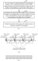
- FIG 4 is a schematic diagram illustrating an implementation process of determining a target time slot number corresponding to an arrival time of a packet according to an embodiment of the present disclosure.
- the process may include the following steps: At step 401, a receiving time stamp of a packet is acquired.
- a receiving time stamp of a packet can be a receiving time stamp put by hardware on the received packet. Some hardware does not support time stamping scenes.
- a system clock of a node can be obtained at a forwarding processing ingress as a receiving time stamp of a packet.
- the receiving time stamp of the packet is converted into a time slot number.
- a target time slot number corresponding to an arrival time of the packet is determined according to the time slot number and a time slot number in a time slot schedule cycle mapping table.
- the time slot number obtained by converting the receiving time stamp of the packet can be divided by the time slot number in the time slot schedule cycle mapping table to take a reminder to obtain the target time slot number corresponding to the arrival time of the packet.
- time slotNum 256
- a time slot schedule cycle mapping table can be queried based on TimeSlotNum_Remainder as keywords to obtain a corresponding cycle schedule queue number.
- the cycle schedule queue number is a queue number of a cycle schedule queue that a packet is to enter at a network node.
- a mapping relationship between a time slot number recorded in a time slot schedule cycle mapping table at the egress interface and a cycle schedule queue number can be determined in the following manner:
- the time slot schedule cycle mapping table can be called a calendar schedule table.
- the calendar schedule table may include the following information and features:
- a number of time slots in the calendar schedule table is an integral multiple of a number/quantity of cycle schedule queues. For example, when the number/quantity of cycle schedule queues is 8, the number of time slots in the calendar schedule table is 8N (N is a positive integer). For example, the number of time slots in the calendar schedule table is 256.
- FIG 5 is a schematic diagram illustrating an implementation process of determining a cycle schedule queue number corresponding to a time slot number according to an embodiment of the present disclosure.
- the process may include: At step 501, for a time slot number, a sum of the time slot number and a schedule offset is divided by a number/quantity of cycle schedule queues at an egress interface to take a remainder to obtain a first remainder result.
- the first remainder result is determined as a cycle schedule queue number corresponding to the time slot number.
- a cycle schedule queue corresponding to the time slot number can be determined according to a sum of the time slot number and a schedule offset. Since the sum of the time slot number and the schedule offset may be greater than a number/quantity of cycle schedule queues, the sum of the time slot number and the schedule offset can be divided by the number/quantity of cycle schedule queues to take a remainder, and a remainder result (i.e., the first remainder result) is determined as a cycle schedule queue number corresponding to the time slot number.
- the cycle schedule queue number Calendar_Que_No corresponding to the time slot number may be determined in the following manner:
- the schedule offset can be used to characterize an offset between a cycle corresponding to a CSQF cycle schedule queue that a packet received by an input forwarding processing unit at time slot 0 enters at a node and a first cycle based on CSQF at the node.
- a method of determining the schedule offset reference may be made to an implementation process illustrated in FIG 6 below, which will not be repeated here.
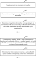
- FIG 6 is a schematic diagram illustrating an implementation process of determining a schedule offset according to an embodiment of the present disclosure.
- the process of determining the schedule offset may include: At step 601, according to a receiving time stamp of a test packet in an input forwarding processing unit, a cycle schedule queue at an egress interface that is being scheduled in an output interface processing unit when the test packet arrives at the output interface processing unit is determined.
- a cycle measurement and calibration method can be used to determine the cycle schedule queue at the egress interface that is being scheduled in the output interface processing unit when the test packet, after being sent from the input forwarding processing unit, arrives at the output interface processing unit.
- an optimal cycle schedule queue of the test packet is determined.
- a next cycle schedule queue of the cycle schedule queue at the egress interface that is being scheduled in the output interface processing unit when the test packet arrives at the output interface processing unit, which is determined in step 601, is the most suitable cycle schedule queue for the test packet to enter.
- a cycle schedule queue that the test packet is to enter can be shifted according to the latency jitter to obtain the optimal cycle schedule queue of the test packet.
- a cycle schedule queue (Queue 6) obtained after a next cycle schedule queue (i.e., Queue 3) of Queue 2 is shifted by 3 queues can be determined as the optimal cycle schedule queue of the test packet.
- the schedule offset is determined according to the optimal cycle schedule queue, a number/quantity of cycle schedule queues at the egress interface, and a time slot number corresponding to the receiving time stamp of the test packet in the input forwarding processing unit.
- an optimal cycle schedule queue corresponding to the time slot number corresponding to the receiving time stamp of the test packet in the input forwarding processing unit can be determined, that is, a corresponding relationship between the time slot number and the optimal cycle schedule queue can be obtained.
- an optimal cycle schedule queue corresponding to time slot 0 can be determined.
- An optimal cycle schedule queue number can be used as the schedule offset.
- the test packet when the schedule offset is determined, can be constructed by CPU, and is transmitted to the input forwarding processing unit through an internal processing channel.
- the input forwarding processing unit can put the receiving time stamp for the test packet according to a system time of receiving the test packet, and determine, according to the receiving time stamp, the cycle schedule queue at the egress interface for the test packet that is being scheduled in the output interface processing unit when the test packet arrives at the output interface processing unit.
- the test packet can be constructed by the input forwarding processing unit.
- the input forwarding processing unit can construct the test packet when receiving a test command.
- the input forwarding processing unit can put the receiving time stamp for the test packet according to a system time when the construction of the test packet is completed, and determine, according to the receiving time stamp, the cycle schedule queue at the egress interface for the test packet that is being scheduled in the output interface processing unit when the test packet arrives at the output interface processing unit.
- the test packet can be forwarded in a processing manner consistent with that after a DT packet arrives at an input forwarding processing unit at an edge node in a CSQF domain, so as to simulate the forwarding process of the DT packet at the edge node in the CSQF domain.
- an input interface processing unit puts the receiving time stamp for the packet, determines a corresponding time slot number (i.e., the target time slot number) according to the receiving time stamp, and maps a cycle schedule queue according to the above method.
- a time slot number i.e., the target time slot number
- the schedule offset obtained by testing according to the above method can more accurately absorb intra-node jitter.
- the test packet can be received in the input forwarding processing unit, or on the basis of the system time when the construction of the test packet is completed, a fixed time (corresponding to the latency of the packet arriving at the input forwarding processing unit through the input interface processing unit) is subtracted to obtain the receiving time stamp of the test packet.
- determining the schedule offset according to the optimal cycle schedule queue, the number/quantity of cycle schedule queues at the egress interface, and the time slot number corresponding to the receiving time stamp of the test packet in the input forwarding processing unit includes:
- the time slot difference should be consistent with a difference between the optimal cycle schedule queue number of the test packet and the optimal cycle schedule queue number corresponding to time slot 0.
- the optimal cycle schedule queue number corresponding to time slot 0 should be a cycle schedule queue number obtained after cycle schedule queue RQ is returned by n cycles.
- n may be greater than a number of cycles
- n can be divided by the number/quantity of cycle schedule queues at the egress interface to take a remainder to obtain a remainder result (i.e., the second remainder result), and optimal cycle schedule queue RQ of the test packet is returned by the second remainder result of cycles.
- RQ may be smaller than the second remainder result
- the number/quantity of cycle schedule queues at the egress interface can be added first, then RQ is returned by the second remainder result of cycles, and an obtained cycle schedule queue number is divided by the number/quantity of cycle schedule queues at the egress interface to take a remainder to obtain a remainder result (i.e., the third remainder result), which is the schedule offset.
- queue 3 is theoretically the most suitable queue for the test packet to enter.
- a time slot update table is required to adjust a time slot number corresponding to an arrival time of each DT.
- a cycle of User 1 sending a packet is 730us (that is, 73 schedule cycles), where a time slot number corresponding to an arrival time of a first packet from the user is 53, and a time slot number corresponding to an arrival time of a second packet from the user is 26.
- time slot table in FIG 9 can be updated, and time slot numbers of packets with time slot numbers 72 and 74 corresponding to an arrival time are updated to 73, that is, the packets are scheduled to a cycle schedule queue corresponding to time slot 73.
- a cycle interval is 73 time slots (730us), and a first packet from the user is at time slot 53, a second packet is at time slot 26, ....
- a time slot update table as shown in FIG 9 is designed. Packets that should be at time slots 72 and 74 are scheduled to a forwarding queue corresponding to time slot 73.
- Calendar_Slot is a time slot number calculated according to a receiving time stamp of a packet
- Calendar_Slot_Replace is an updated time slot number
- time slot numbers corresponding to an arrival time of the DT include 0, 1 and 2
- the time slot numbers can be mapped to time slot number 2, so as to implement the shaping of the DT.
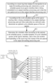
- the process of a DT transmission method may be as shown in FIG 10 .
- the process may include the following steps: At step 1001, in a case where it is determined that a received packet belongs to a DT, and the packet does not carry CSQF domain schedule information, a target time slot number corresponding to an arrival time of the packet is determined.
- a time slot update table of a service flow to which the packet belongs is queried according to the target time slot number to obtain an updated time slot number.
- a time slot schedule cycle mapping table at an egress interface for the packet is queried, and a target cycle schedule queue corresponding to a time slot at which the packet arrives is determined.
- the packet is scheduled to the target cycle schedule queue at the egress interface for the packet.
- the time slot update table By generating the time slot update table, the conflict problem between DT schedule time slots at an edge node in a CSQF domain is effectively solved, the adaptability of CSQF is enhanced, and the DT carrying capacity on the same path can be improved.
- the shaping of a DT can be implemented.
- DTs received thereby are from a deterministic domain. There is usually no need to shape the DTs. There will not be a situation where some time slots are less used, and some time slots are more used.
- the edge node that is connected to the non-wide area DetNet (such as TSN) in the wide area DetNet, or the forwarding relay node of CSQF on the super-long path in the wide area DetNet a number/quantity of DTs that is to be processed thereby is usually larger. If the time slot update table is configured and delivered for each DT, huge resources will be consumed. Therefore, in practical applications, for the edge node that is connected to the non-wide area DetNet (such as TSN) in the wide area DetNet, or the forwarding relay node of CSQF on the super-long path in the wide area DetNet, the time slot update table may not be configured and delivered.
- a time slot update table can be delivered for each DT.
- a model of forwarding a DT packet by an edge node in a CSQF domain will be described below with reference to FIG 11 .
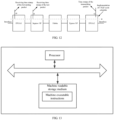
- FIG 11 is a schematic diagram illustrating intra-node latency decomposition of a model of forwarding a DT packet by an edge node in a CSQF domain according to an embodiment of the present disclosure.
- the process of forwarding a DT packet by an edge node in a CSQF domain includes: an input process, a distributing process, a switch process, a mapping process, a schedule by cycle process, and an output process.
- Input Process used for anchoring input time stamps.
- the input process is mainly a function of a hardware controller for implementing the anchoring of input time stamps.
- Distributing Process used for cache distribution.
- the distributing process may be implemented by a hardware controller, or by software.
- Switch Process used for intra-node forwarding related processing.
- the switch process may include software processing, and microcodes from an NP cooperate with a hardware unit to implement a pipeline.
- it may further include the switch processing of input interface board -> network board -> output interface board.
- FIG 12 For specific implementation, reference may be made to an implementation process illustrated in FIG 12 below, which will not be repeated here.
- Mapping Process used for mapping DT packets to cycle schedule queues according to cycles.
- software or microcodes from NP or Field Programmable Gate Array (FPGA) is to participate in the mapping process, and programmability is required to provide implementation flexibility.
- FPGA Field Programmable Gate Array
- Schedule by Cycle Process used for scheduling cycle schedule queues according to schedule cycles, and sending data in sending cycle queues to hardware queues configured with a reserved highest priority.
- hardware queues configured with a reserved highest priority can be used as hardware queues for sending DTs, and output time stamps are put.
- processing latency in the switch process is indeterminate, involving intra-node queuing, and there may be a difference of up to 20us ⁇ 50us.
- a switch process of a distributed device is taken as an example.
- FIG 12 is a schematic diagram illustrating a forwarding model in a switch process of a distributed device according to an embodiment of the present disclosure.
- processing latency in the switch process may include processing latency in an input forwarding processing unit (for example, an Ingress NP in FIG 12 ), an internal switch unit (for example, Fabric in FIG 12 ), and an output forwarding processing unit (for example, an Egress NP in FIG 12 ), and superimposed jitter there-among may reach more than 20us.
- an input forwarding processing unit for example, an Ingress NP in FIG 12
- an internal switch unit for example, Fabric in FIG 12
- an output forwarding processing unit for example, an Egress NP in FIG 12
- both the two stages of Mapping and Schedule by Cycle are implemented by an output interface processing unit (for example, FPGA2 in FIG 12 ), and there is larger indeterminate latency jitter (i.e., intra-node jitter) in the mapping process of a packet entering from an input interface processing unit (for example, FPGA1 in FIG 12 ) to the output interface processing unit.
- an output interface processing unit for example, FPGA2 in FIG 12
- indeterminate latency jitter i.e., intra-node jitter
- FPGA1 and FPGA2 may be different FPGAs, or the same FPGA (for example, scenes of traffic loopback or scenes where the same FPGA implements multiple external ports).
- a schedule offset can be determined by testing in the above-described manners.
- a schedule offset is determined, according to a receiving time stamp of a test packet in an Ingress NP, a cycle schedule queue at an egress interface for the test packet that is being scheduled in FPGA2 when the test packet arrives at FPGA2 can be determined; according to the cycle schedule queue and intra-node latency, such as 30us, an optimal cycle schedule queue of the test packet is determined; according to an optimal cycle schedule queue number, and a time slot number corresponding to the receiving time stamp of the test packet in the Ingress NP, the schedule offset is determined in the above-described manners.
- FIG 13 is a schematic diagram illustrating a hardware structure of an electronic device according to an embodiment of the present disclosure.
- the electronic device includes a processor and a machine readable storage medium, where machine executable instructions that can be executed by the processor are stored in the machine readable storage medium; and the processor is configured to execute the machine executable instructions to implement the methods disclosed in the embodiments of the present disclosure.
- the processor executes the machine executable instructions to: in a case where it is determined that a received packet belongs to a DT, and the packet does not carry CSQF domain schedule information, determine a target time slot number corresponding to an arrival time of the packet; according to the target time slot number, query a time slot schedule cycle mapping table at an egress interface for the packet, and determine a target cycle schedule queue corresponding to the target time slot number, where the time slot schedule cycle mapping table is determined based on intra-node jitter at the network node, and is used to record a mapping relationship between a time slot number and a cycle schedule queue number; schedule the packet to the target cycle schedule queue at the egress interface for the packet.
- the processor executes the machine executable instructions to: acquire a receiving time stamp of the packet; convert the receiving time stamp of the packet into a time slot number; determine the target time slot number corresponding to the arrival time of the packet according to the time slot number and a time slot number in the time slot schedule cycle mapping table.
- the processor executes the machine executable instructions to: for an egress interface that supports CSQF, determine the mapping relationship between the time slot number and the cycle schedule queue number recorded in the time slot schedule cycle mapping table at the egress interface in the following manners: for a time slot number, determining a cycle schedule queue number corresponding to the time slot number according to the time slot number, a schedule offset, and a number/quantity of cycle schedule queues at the egress interface, where the schedule offset is determined according to the intra-node jitter at the network node.
- the processor executes the machine executable instructions to: divide a sum of the time slot number and the schedule offset by the number/quantity of cycle schedule queues at the egress interface to take a remainder to obtain a first remainder result; determine the first remainder result as the cycle schedule queue number corresponding to the time slot number.
- the processor executes the machine executable instructions to: determine the schedule offset in the following manners: according to a receiving time stamp of a test packet in an input forwarding processing unit, determining a cycle schedule queue at the egress interface that is being scheduled in an output interface processing unit when the test packet arrives at the output interface processing unit; according to the cycle schedule queue at the egress interface that is being scheduled in the output interface processing unit and the intra-node jitter at the network node, determining an optimal cycle schedule queue of the test packet; determining the schedule offset according to the optimal cycle schedule queue, the number/quantity of cycle schedule queues at the egress interface, and a time slot number corresponding to the receiving time stamp of the test packet in the input forwarding processing unit.
- the processor executes the machine executable instructions to: divide the time slot number corresponding to the receiving time stamp of the test packet in the input forwarding processing unit by the number/quantity of cycle schedule queues to take a remainder to obtain a second remainder result; sum an optimal cycle schedule queue number and the number/quantity of cycle schedule queues at the egress interface to obtain a summation result; divide a difference between the summation result and the second remainder result by the number/quantity of cycle schedule queues at the egress interface to take a remainder to obtain a third remainder result; determine the third remainder result as the schedule offset.
- the processor executes the machine executable instructions to: query a time slot update table of a service flow to which the packet belongs according to the target time slot number to obtain an updated time slot number; according to the updated time slot number, query the time slot schedule cycle mapping table at the egress interface for the packet, and determine a target cycle schedule queue corresponding to a time slot at which the packet arrives.
- a process of forwarding a DT packet by an edge node in a CSQF domain includes:
- the intra-node jitter at the network node includes processing latency jitter in the switch process.
- a non-transitory machine readable storage medium storing computer executable instructions, such as the machine readable storage medium in FIG 13 , where the computer executable instructions can be executed by a processor 801 in the electronic device shown in FIG 13 to implement the method for analyzing data flows as described above.
- the machine readable storage medium may be any electronic, magnetic, optical, or other physical storage apparatus, and may contain or store information, such as executable instructions, and data.
- the machine readable storage medium may be: a Radom Access Memory (RAM for short), a volatile memory, a non-volatile memory, a flash memory, a storage drive (such as hard drive), a solid state hard disk, any type of storage disk (such as optical discs, and Digital Video Disks (DVDs for short)), or similar storage medium, or a combination of them.
- the system, apparatus, module or unit set forth in the above examples may be specifically implemented by a computer chip or an entity, or implemented by a product having a certain function.
- a typical implementation device is a computer, and a specific form of the computer may be a personal computer, a laptop computer, a cellular phone, a camera phone, a smart phone, a personal digital assistant, a media player, a navigation device, an e-mail transceiver device, a game console, a tablet computer, a wearable device, or a combination of any of these devices.
- the embodiments of the present disclosure may be provided as methods, systems, or computer program products. Accordingly, the present disclosure may take the form of a pure hardware embodiment, a pure software embodiment, or an embodiment combining software and hardware aspects. Furthermore, the embodiments of the present disclosure may take the form of a computer program product implemented on one or more computer usable storage media (including, but not limited to, disk storage, Compact Disc Read - Only Memory (CD-ROM for short), optical storage, etc.) having computer usable program codes therein.
- CD-ROM Compact Disc Read - Only Memory
- these computer program instructions may be stored in a computer readable memory capable of directing a computer or other programmable data processing device to operate in a particular manner, so that the instructions stored in the computer readable memory produce a product including an instruction device.
- the instruction device can realize functions specified in one or more processes in a flowchart and/or one or more blocks in a block diagram.
- These computer program instructions may be loaded on a computer or other programmable data processing device, so that a series of operation steps are performed on the computer or other programmable device to produce processes implemented by a computer, and the instructions executed on the computer or other programmable device provide steps for realizing functions specified in one or more processes in a flowchart and/or one or more blocks in a block diagram.
Landscapes
- Engineering & Computer Science (AREA)
- Computer Networks & Wireless Communication (AREA)
- Signal Processing (AREA)
- Environmental & Geological Engineering (AREA)
- Health & Medical Sciences (AREA)
- Cardiology (AREA)
- General Health & Medical Sciences (AREA)
- Data Exchanges In Wide-Area Networks (AREA)
Applications Claiming Priority (1)
| Application Number | Priority Date | Filing Date | Title |
|---|---|---|---|
| PCT/CN2021/142636 WO2023123103A1 (zh) | 2021-12-29 | 2021-12-29 | 确定性流传输方法及设备 |
Publications (2)
| Publication Number | Publication Date |
|---|---|
| EP4336900A1 true EP4336900A1 (de) | 2024-03-13 |
| EP4336900A4 EP4336900A4 (de) | 2024-08-07 |
Family
ID=86996908
Family Applications (1)
| Application Number | Title | Priority Date | Filing Date |
|---|---|---|---|
| EP21969471.8A Pending EP4336900A4 (de) | 2021-12-29 | 2021-12-29 | Verfahren und vorrichtung zur deterministischen verkehrsübertragung |
Country Status (5)
| Country | Link |
|---|---|
| US (1) | US12432159B2 (de) |
| EP (1) | EP4336900A4 (de) |
| JP (1) | JP7685077B2 (de) |
| CN (1) | CN116530141A (de) |
| WO (1) | WO2023123103A1 (de) |
Families Citing this family (4)
| Publication number | Priority date | Publication date | Assignee | Title |
|---|---|---|---|---|
| CN119485672A (zh) * | 2023-08-11 | 2025-02-18 | 中兴通讯股份有限公司 | 周期调度时隙接入控制方法、电子设备、计算机可读介质 |
| WO2025050277A1 (zh) * | 2023-09-05 | 2025-03-13 | 新华三技术有限公司 | 确定性流传输方法、装置及网络节点 |
| CN119948843B (zh) * | 2023-09-05 | 2025-11-25 | 新华三技术有限公司 | 确定性流传输方法、装置及网络节点 |
| CN119966915A (zh) * | 2023-11-08 | 2025-05-09 | 中兴通讯股份有限公司 | 业务传输方法、设备及存储介质 |
Family Cites Families (16)
| Publication number | Priority date | Publication date | Assignee | Title |
|---|---|---|---|---|
| CN110138813B (zh) | 2018-02-02 | 2021-11-19 | 华为技术有限公司 | 一种传输数据的方法、通信装置及用户面功能实体 |
| US10587501B2 (en) * | 2018-05-23 | 2020-03-10 | Cisco Technology, Inc. | Emergency packet transmission allocation within time multiplexed channel hopping for LLNs |
| EP3857830B1 (de) * | 2018-10-30 | 2025-10-01 | Huawei Technologies Co., Ltd. | Verfahren und vorrichtungen zur terminbewussten flussablaufplanung in zeitsensiblen netzwerken |
| US11005783B2 (en) | 2019-03-22 | 2021-05-11 | Nokia Solutions And Networks Oy | Notification of timing mismatches for queues in time sensitive networking |
| EP3981133B1 (de) * | 2019-07-22 | 2024-09-25 | Huawei Technologies Co., Ltd. | Steuervorrichtung, schaltvorrichtung, verfahren und computerlesbares speichermedium |
| CN112583510B (zh) * | 2019-09-30 | 2025-01-10 | 华为技术有限公司 | 一种报文转发方法、设备及系统 |
| CN113498106B (zh) | 2020-03-18 | 2025-10-28 | 华为技术有限公司 | 一种时间敏感网络tsn流的调度方法及装置 |
| CN112804151B (zh) * | 2021-01-21 | 2022-11-08 | 烽火通信科技股份有限公司 | 一种数据处理的方法、装置以及电子设备 |
| CN112887226B (zh) | 2021-01-26 | 2022-07-22 | 重庆邮电大学 | 有线无线融合的卫星时间敏感网络队列管理调度方法 |
| CN115037399A (zh) * | 2021-03-03 | 2022-09-09 | 中兴通讯股份有限公司 | 报文转发方法、电子设备和存储介质 |
| CN113068263B (zh) | 2021-03-26 | 2022-07-05 | 鹏城实验室 | 一种时间敏感网络时隙调度方法、终端及存储介质 |
| CN113316191B (zh) | 2021-05-26 | 2022-08-23 | 电子科技大学 | 一种基于天地一体化网络的通信方法 |
| WO2023283902A1 (zh) * | 2021-07-15 | 2023-01-19 | 新华三技术有限公司 | 一种报文传输方法及装置 |
| CN113783793B (zh) * | 2021-07-23 | 2023-07-25 | 北京邮电大学 | 对时间敏感的数据帧的流量调度方法及相关设备 |
| CN116266818A (zh) * | 2021-12-17 | 2023-06-20 | 中兴通讯股份有限公司 | 信息测量方法及装置 |
| CN116686324A (zh) | 2021-12-29 | 2023-09-01 | 新华三技术有限公司 | 应用于确定性网中的csqf调度周期收集方法及装置 |
-
2021
- 2021-12-29 CN CN202180004331.0A patent/CN116530141A/zh active Pending
- 2021-12-29 EP EP21969471.8A patent/EP4336900A4/de active Pending
- 2021-12-29 US US18/568,346 patent/US12432159B2/en active Active
- 2021-12-29 JP JP2023574856A patent/JP7685077B2/ja active Active
- 2021-12-29 WO PCT/CN2021/142636 patent/WO2023123103A1/zh not_active Ceased
Also Published As
| Publication number | Publication date |
|---|---|
| CN116530141A (zh) | 2023-08-01 |
| EP4336900A4 (de) | 2024-08-07 |
| US12432159B2 (en) | 2025-09-30 |
| US20240275735A1 (en) | 2024-08-15 |
| WO2023123103A1 (zh) | 2023-07-06 |
| JP2024520161A (ja) | 2024-05-21 |
| JP7685077B2 (ja) | 2025-05-28 |
Similar Documents
| Publication | Publication Date | Title |
|---|---|---|
| US12432159B2 (en) | Deterministic traffic transmission method and device | |
| US5859835A (en) | Traffic scheduling system and method for packet-switched networks | |
| US9094231B2 (en) | Router | |
| JP7683047B2 (ja) | 決定論的ネットワークに適用されるcsqfスケジューリングサイクルを収集するための方法及び装置 | |
| JP2014522202A (ja) | パケットを再構築し再順序付けするための方法、装置、およびシステム | |
| US20240323136A1 (en) | Packet transmission method and network device | |
| CN109729013A (zh) | 一种流量整形中添加令牌的方法、装置及计算机可读存储介质 | |
| US20150304227A1 (en) | Queue Management Method and Apparatus | |
| CN114553792B (zh) | 调度参数的调整方法、装置、设备及计算机可读存储介质 | |
| Tabatabaee et al. | QoS provisioning and tracking fluid policies in input queueing switches | |
| CN117714368A (zh) | 一种基于分段路由的确定性时延路由调度方法和系统 | |
| CN121125660A (zh) | 一种基于fpga的智能网卡数据转发方法及系统 | |
| CN119586109B (zh) | 确定性流传输方法、装置、电子设备及机器可读存储介质 | |
| JP2019149043A (ja) | 見積り装置および見積り方法 | |
| CN113824606B (zh) | 一种网络测量方法及装置 | |
| CN114490458A (zh) | 数据传输方法、芯片、服务器以及存储介质 | |
| CN119484418B (zh) | 基于时间基准的同步和异步融合的流量整形方法和装置 | |
| Moltafet et al. | Average age of information for a multi-source M/M/1 queueing model with packet management and self-preemption in service | |
| Song et al. | Priority-based grant-aware scheduling for low-latency switching | |
| Lygdenov | Efficiency in Multi-Channel Data Transmission Systems with Priority Service Under High Load | |
| CN115623093B (en) | Message collection method and system | |
| CN116708198B (zh) | 确定性信令的实现方法、装置、电子设备及存储介质 | |
| WO2025129991A1 (zh) | 一种确定性业务的周期化处理方法及系统 | |
| CN121357094A (zh) | 智能变电站确定性网络通信无等待调度方法、系统及介质 | |
| EP4627783A1 (de) | Latenzbestimmung in einem netzwerkknoten |
Legal Events
| Date | Code | Title | Description |
|---|---|---|---|
| STAA | Information on the status of an ep patent application or granted ep patent |
Free format text: STATUS: THE INTERNATIONAL PUBLICATION HAS BEEN MADE |
|
| PUAI | Public reference made under article 153(3) epc to a published international application that has entered the european phase |
Free format text: ORIGINAL CODE: 0009012 |
|
| STAA | Information on the status of an ep patent application or granted ep patent |
Free format text: STATUS: REQUEST FOR EXAMINATION WAS MADE |
|
| 17P | Request for examination filed |
Effective date: 20231207 |
|
| AK | Designated contracting states |
Kind code of ref document: A1 Designated state(s): AL AT BE BG CH CY CZ DE DK EE ES FI FR GB GR HR HU IE IS IT LI LT LU LV MC MK MT NL NO PL PT RO RS SE SI SK SM TR |
|
| A4 | Supplementary search report drawn up and despatched |
Effective date: 20240708 |
|
| RIC1 | Information provided on ipc code assigned before grant |
Ipc: H04L 47/00 20220101ALI20240702BHEP Ipc: H04L 47/56 20220101ALI20240702BHEP Ipc: H04L 47/28 20220101ALI20240702BHEP Ipc: H04L 43/50 20220101ALI20240702BHEP Ipc: H04L 43/0852 20220101ALI20240702BHEP Ipc: H04L 43/106 20220101ALI20240702BHEP Ipc: H04W 28/24 20090101AFI20240702BHEP |
|
| DAV | Request for validation of the european patent (deleted) | ||
| DAX | Request for extension of the european patent (deleted) |