EP4336909A1 - Verfahren und vorrichtung zur stromsparmodusübertragung - Google Patents
Verfahren und vorrichtung zur stromsparmodusübertragung Download PDFInfo
- Publication number
- EP4336909A1 EP4336909A1 EP22806534.8A EP22806534A EP4336909A1 EP 4336909 A1 EP4336909 A1 EP 4336909A1 EP 22806534 A EP22806534 A EP 22806534A EP 4336909 A1 EP4336909 A1 EP 4336909A1
- Authority
- EP
- European Patent Office
- Prior art keywords
- communication apparatus
- duration
- psm
- psm mode
- indication information
- Prior art date
- Legal status (The legal status is an assumption and is not a legal conclusion. Google has not performed a legal analysis and makes no representation as to the accuracy of the status listed.)
- Pending
Links
- 238000000034 method Methods 0.000 title claims abstract description 100
- 230000005540 biological transmission Effects 0.000 title claims abstract description 45
- 238000004891 communication Methods 0.000 claims abstract description 308
- 230000004044 response Effects 0.000 claims abstract description 67
- 238000004590 computer program Methods 0.000 claims description 15
- 238000012545 processing Methods 0.000 claims description 14
- 238000012544 monitoring process Methods 0.000 description 39
- 230000006870 function Effects 0.000 description 28
- 230000015654 memory Effects 0.000 description 24
- 238000010586 diagram Methods 0.000 description 18
- 230000008569 process Effects 0.000 description 17
- 238000005516 engineering process Methods 0.000 description 10
- 238000013461 design Methods 0.000 description 8
- 239000002699 waste material Substances 0.000 description 8
- 230000011664 signaling Effects 0.000 description 5
- 230000008878 coupling Effects 0.000 description 3
- 238000010168 coupling process Methods 0.000 description 3
- 238000005859 coupling reaction Methods 0.000 description 3
- 238000010295 mobile communication Methods 0.000 description 3
- 230000004913 activation Effects 0.000 description 2
- 230000001413 cellular effect Effects 0.000 description 2
- 238000011161 development Methods 0.000 description 2
- 230000000977 initiatory effect Effects 0.000 description 2
- 230000003993 interaction Effects 0.000 description 2
- 230000007774 longterm Effects 0.000 description 2
- 230000007246 mechanism Effects 0.000 description 2
- 230000009471 action Effects 0.000 description 1
- 238000013475 authorization Methods 0.000 description 1
- 238000004422 calculation algorithm Methods 0.000 description 1
- 238000004364 calculation method Methods 0.000 description 1
- 230000008859 change Effects 0.000 description 1
- 238000012217 deletion Methods 0.000 description 1
- 230000037430 deletion Effects 0.000 description 1
- 238000001514 detection method Methods 0.000 description 1
- 230000004069 differentiation Effects 0.000 description 1
- 239000011521 glass Substances 0.000 description 1
- 238000005259 measurement Methods 0.000 description 1
- 230000006855 networking Effects 0.000 description 1
- 230000003287 optical effect Effects 0.000 description 1
- 230000009467 reduction Effects 0.000 description 1
- 239000004984 smart glass Substances 0.000 description 1
Images




Classifications
-
- H—ELECTRICITY
- H04—ELECTRIC COMMUNICATION TECHNIQUE
- H04W—WIRELESS COMMUNICATION NETWORKS
- H04W52/00—Power management, e.g. Transmission Power Control [TPC] or power classes
- H04W52/02—Power saving arrangements
- H04W52/0209—Power saving arrangements in terminal devices
- H04W52/0225—Power saving arrangements in terminal devices using monitoring of external events, e.g. the presence of a signal
-
- H—ELECTRICITY
- H04—ELECTRIC COMMUNICATION TECHNIQUE
- H04W—WIRELESS COMMUNICATION NETWORKS
- H04W52/00—Power management, e.g. Transmission Power Control [TPC] or power classes
- H04W52/02—Power saving arrangements
- H04W52/0209—Power saving arrangements in terminal devices
- H04W52/0212—Power saving arrangements in terminal devices managed by the network, e.g. network or access point is leader and terminal is follower
- H04W52/0216—Power saving arrangements in terminal devices managed by the network, e.g. network or access point is leader and terminal is follower using a pre-established activity schedule, e.g. traffic indication frame
-
- H—ELECTRICITY
- H04—ELECTRIC COMMUNICATION TECHNIQUE
- H04W—WIRELESS COMMUNICATION NETWORKS
- H04W52/00—Power management, e.g. Transmission Power Control [TPC] or power classes
- H04W52/02—Power saving arrangements
- H04W52/0209—Power saving arrangements in terminal devices
- H04W52/0225—Power saving arrangements in terminal devices using monitoring of external events, e.g. the presence of a signal
- H04W52/0229—Power saving arrangements in terminal devices using monitoring of external events, e.g. the presence of a signal where the received signal is a wanted signal
- H04W52/0235—Power saving arrangements in terminal devices using monitoring of external events, e.g. the presence of a signal where the received signal is a wanted signal where the received signal is a power saving command
-
- H—ELECTRICITY
- H04—ELECTRIC COMMUNICATION TECHNIQUE
- H04W—WIRELESS COMMUNICATION NETWORKS
- H04W52/00—Power management, e.g. Transmission Power Control [TPC] or power classes
- H04W52/02—Power saving arrangements
- H04W52/0209—Power saving arrangements in terminal devices
- H04W52/0225—Power saving arrangements in terminal devices using monitoring of external events, e.g. the presence of a signal
- H04W52/0245—Power saving arrangements in terminal devices using monitoring of external events, e.g. the presence of a signal according to signal strength
-
- H—ELECTRICITY
- H04—ELECTRIC COMMUNICATION TECHNIQUE
- H04W—WIRELESS COMMUNICATION NETWORKS
- H04W52/00—Power management, e.g. Transmission Power Control [TPC] or power classes
- H04W52/02—Power saving arrangements
- H04W52/0209—Power saving arrangements in terminal devices
- H04W52/0261—Power saving arrangements in terminal devices managing power supply demand, e.g. depending on battery level
- H04W52/0274—Power saving arrangements in terminal devices managing power supply demand, e.g. depending on battery level by switching on or off the equipment or parts thereof
- H04W52/028—Power saving arrangements in terminal devices managing power supply demand, e.g. depending on battery level by switching on or off the equipment or parts thereof switching on or off only a part of the equipment circuit blocks
-
- H—ELECTRICITY
- H04—ELECTRIC COMMUNICATION TECHNIQUE
- H04W—WIRELESS COMMUNICATION NETWORKS
- H04W76/00—Connection management
- H04W76/20—Manipulation of established connections
- H04W76/28—Discontinuous transmission [DTX]; Discontinuous reception [DRX]
-
- H—ELECTRICITY
- H04—ELECTRIC COMMUNICATION TECHNIQUE
- H04B—TRANSMISSION
- H04B7/00—Radio transmission systems, i.e. using radiation field
- H04B7/14—Relay systems
- H04B7/15—Active relay systems
- H04B7/185—Space-based or airborne stations; Stations for satellite systems
- H04B7/1851—Systems using a satellite or space-based relay
- H04B7/18513—Transmission in a satellite or space-based system
-
- Y—GENERAL TAGGING OF NEW TECHNOLOGICAL DEVELOPMENTS; GENERAL TAGGING OF CROSS-SECTIONAL TECHNOLOGIES SPANNING OVER SEVERAL SECTIONS OF THE IPC; TECHNICAL SUBJECTS COVERED BY FORMER USPC CROSS-REFERENCE ART COLLECTIONS [XRACs] AND DIGESTS
- Y02—TECHNOLOGIES OR APPLICATIONS FOR MITIGATION OR ADAPTATION AGAINST CLIMATE CHANGE
- Y02D—CLIMATE CHANGE MITIGATION TECHNOLOGIES IN INFORMATION AND COMMUNICATION TECHNOLOGIES [ICT], I.E. INFORMATION AND COMMUNICATION TECHNOLOGIES AIMING AT THE REDUCTION OF THEIR OWN ENERGY USE
- Y02D30/00—Reducing energy consumption in communication networks
- Y02D30/70—Reducing energy consumption in communication networks in wireless communication networks
Definitions
- This application relates to the field of communication technologies, and more specifically, to a method and an apparatus for power saving mode (power saving mode, PSM) transmission.
- PSM power saving mode
- a PSM is a new low power mode introduced in an internet of things (internet of things, IoT) scenario.
- IoT internet of things
- the communication apparatus may request PSM information from a network. After obtaining the PSM information, the communication apparatus may enter the PSM mode.
- the communication apparatus In the PSM mode, the communication apparatus is unreachable, that is, the network cannot communicate with the communication apparatus, so that the communication apparatus enters a long-term deep sleep state, to achieve the purpose of power loss reduction.
- the communication apparatus may exit the PSM mode to transit to a connected state.
- a satellite base station moves at a high speed
- the communication apparatus exits the PSM mode there may be no satellite base station that is in a cell where the communication apparatus is currently located and that can communicate with the communication apparatus, in other words, the communication apparatus exits the PSM mode at an inappropriate time point. As a result, a waste of power is caused.
- This application provides a method and an apparatus for power saving mode PSM transmission, to help a communication apparatus wake up from a PSM mode at an appropriate time point, to reduce a waste of power.
- a method for power saving mode PSM transmission includes: A first communication apparatus sends a first request message, where the first request message is for requesting to enter a PSM mode.
- the first communication apparatus receives a first response message, where the first response message includes first indication information and second indication information, the first indication information indicates the first communication apparatus to enter the PSM mode, the second indication information indicates X wakeup occasion windows for the first communication apparatus in the PSM mode, and X is greater than or equal to 0.
- the first communication apparatus enters the PSM mode based on the first response message.
- the first communication apparatus when receiving the first indication information indicating to enter the PSM mode, the first communication apparatus further receives the indicated X wakeup occasion windows for the first communication apparatus in the PSM mode. In the wakeup occasion window, the first communication apparatus may temporarily wake up to process uplink and downlink service data. In this way, the first communication apparatus may wake up in an appropriate period, to reduce power loss of the first communication apparatus.
- the second indication information when X is greater than 0, includes a start time point and an end time point of each of the X wakeup occasion windows, or a start time point and duration of each wakeup occasion window.
- the first communication apparatus may determine an appropriate wakeup occasion window based on the start time point and the end time point or the start time point and the duration of each indicated wakeup occasion window. In this way, the indication is simple and intuitive, facilitating processing performed by the first communication apparatus.
- the first communication apparatus after the first communication apparatus enters the PSM mode based on the first response message, if the first communication apparatus has to-be-sent service data, the first communication apparatus sends the service data in a first wakeup occasion window of the X wakeup occasion windows.
- the first communication apparatus may select the first wakeup occasion window from the X wakeup occasion windows to send the service data. This facilitates normal transmission of the service data, and reduces power loss.
- the first response message is an attach accept message or a tracking area update accept message.
- the second indication information indicating the X wakeup occasion windows may be transmitted via the attach accept message or the tracking area update accept message, to help reduce signaling overheads.
- the first communication apparatus receives information about first duration, where the first duration indicates delay time of the PSM mode. That the first communication apparatus enters the PSM mode based on the first response message includes: After receiving the first response message, the first communication apparatus enters the PSM mode after the first duration elapses.
- the delay time that is, the first duration
- the first communication apparatus enters the PSM mode after the first duration elapses. This helps the first communication apparatus receive a paging message before entering the PSM mode.
- the first communication apparatus receives information about second duration, where the second duration indicates duration of the PSM mode. After entering the PSM mode, the first communication apparatus exits the PSM mode after the second duration elapses.
- the first communication apparatus may exit the PSM mode after the second duration elapses, to avoid that the first communication apparatus does not update location information in a timely manner because the first communication apparatus is in the PSM mode for a long time.
- a method for power saving mode PSM transmission includes: A second communication apparatus receives a first request message, where the first request message is for requesting to enter a PSM mode.
- the second communication apparatus sends a first response message, where the first response message includes first indication information and second indication information, the first indication information indicates a first communication apparatus to enter the PSM mode, the second indication information indicates X wakeup occasion windows for the first communication apparatus in the PSM mode, and X is greater than or equal to 0.
- the second indication information when X is greater than 0, includes a start time point and an end time point of each of the X wakeup occasion windows, or a start time point and duration of each wakeup occasion window.
- the first response message is an attach accept message or a tracking area update accept message.
- the second communication apparatus sends information about first duration, where the first duration indicates delay time of the PSM mode.
- the second communication apparatus sends information about second duration, where the second duration indicates duration of the PSM mode.
- a method for monitoring a paging message includes: A first communication apparatus sends a second request message, where the second request message is for requesting a monitoring occasion of a paging message.
- the first communication apparatus receives a second response message, where the second response message includes third indication information or fourth indication information, the third indication information indicates a paging cycle in which the first communication apparatus monitors the paging message, and the fourth indication information indicates a time period in which the first communication apparatus stops monitoring the paging message.
- the first communication apparatus monitors the paging message based on the second response message.
- the third indication information or the fourth indication information may indicate an occasion on which the first communication apparatus monitors the paging message or stops monitoring the paging message. In this way, the first communication apparatus does not monitor the paging message when there is no network connection, to reduce a waste of power consumption.
- the fourth indication information includes a start time point and an end time point of the period in which monitoring of the paging message is stopped, or a start time point and duration of the period in which monitoring of the paging message is stopped.
- the first communication apparatus monitors the paging message based on the second response message includes: The first communication apparatus determines, from at least one paging cycle based on the third indication information, a target paging cycle in which the paging message is monitored. The first communication apparatus monitors the paging message in the target paging cycle.
- the first communication apparatus has at least one paging cycle, but the paging message may not be monitored in a specific paging cycle. Therefore, the third indication information may indicate the target paging cycle of the at least one paging cycle in which the paging message may be monitored. This helps reduce power loss.
- the first communication apparatus monitors the paging message based on the second response message includes: The first communication apparatus determines, based on the fourth indication information, a period in which monitoring of the paging message is stopped. The first communication apparatus continues to monitor the paging message after the period in which monitoring of the paging message is stopped elapses.
- the fourth indication information may indicate the period in which monitoring of the paging message is stopped. In the period in which monitoring of the paging message is stopped, the first communication apparatus cannot monitor the paging message. Therefore, the first communication apparatus does not need to perform monitoring in the period in which monitoring of the paging message is stopped. This helps reduce power loss.
- a method for monitoring a paging message includes: A second communication apparatus receives a second request message, where the second request message is for requesting a monitoring occasion of a paging message.
- the second communication apparatus sends a second response message, where the second response message includes third indication information or fourth indication information, the third indication information indicates a paging cycle in which a first communication apparatus monitors the paging message, and the fourth indication information indicates a period in which the first communication apparatus stops monitoring the paging message.
- the fourth indication information includes a start time point and an end time point or a start time point and duration of the period in which monitoring of the paging message is stopped.
- the second communication apparatus receives a paging message, where the paging message includes a period indicating the second communication apparatus to stop sending the paging message.
- the second communication apparatus stops sending the paging message in the period in which the second communication apparatus stops sending the paging message.
- an apparatus for power saving mode PSM transmission configured to perform the method according to any possible implementation of any one of the foregoing aspects.
- the apparatus includes a module configured to perform the method according to any possible implementation of any one of the foregoing aspects.
- the apparatus may include modules for one-to-one correspondingly performing the methods/operations/steps/actions described in the foregoing aspects.
- the module may be a hardware circuit, or may be software, or may be implemented by a hardware circuit in combination with software.
- the apparatus is a communication chip.
- the communication chip may include an input circuit or an interface configured to send information or data, and an output circuit or an interface configured to receive information or data.
- the apparatus is a communication device, including a transmitter configured to send information or data and a receiver configured to receive information or data.
- the apparatus is configured to perform the method according to any one of the foregoing aspects or the possible implementations of the foregoing aspects.
- the apparatus may be configured in the first communication apparatus or the second communication apparatus, or the apparatus is the first communication apparatus or the second communication apparatus.
- another apparatus for power saving mode PSM transmission including a processor and a memory.
- the memory is configured to store a computer program
- the processor is configured to invoke the computer program from the memory and run the computer program, so that the apparatus performs the method according to any possible implementation of any one of the foregoing aspects.
- processors there are one or more processors, and there are one or more memories.
- the memory may be integrated with the processor, or the memory and the processor are separately disposed.
- the communication device further includes a transmitter (transmitter) and a receiver (receiver).
- the transmitter and the receiver may be disposed separately, or may be integrated together, and are referred to as a transceiver (transceiver).
- a communication system including: an apparatus configured to implement the method according to any one of the first aspect or the possible implementations of the first aspect, and an apparatus configured to implement the method according to any one of the second aspect or the possible implementations of the second aspect; or including an apparatus configured to implement the method according to any one of the third aspect or the possible implementations of the third aspect, and an apparatus configured to implement the method according to any one of the fourth aspect or the possible implementations of the fourth aspect.
- the communication system may further include a device that interacts with the first communication apparatus and/or the second communication apparatus in the solutions provided in embodiments of this application.
- a computer program product includes a computer program (which may also be referred to as code or instructions).
- a computer program which may also be referred to as code or instructions.
- a computer-readable medium stores a computer program (which may also be referred to as code or instructions).
- a computer program which may also be referred to as code or instructions.
- the computer program When the computer program is run on a computer, the computer is enabled to perform the method according to any possible implementation of any one of the foregoing aspects.
- a communication apparatus including a communication interface and a logic circuit.
- the communication interface is configured to send a first request message and/or receive a first response message
- the logic circuit is configured to enter a PSM based on the first response message, to perform the method according to any possible implementation of the first aspect.
- another communication apparatus including a communication interface and a logic circuit.
- the communication interface is configured to receive a first request message and/or send a first response message.
- the logic circuit is configured to transmit a PSM based on the first request message to perform the method according to any possible implementation of the second aspect.
- still another communication apparatus including a communication interface and a logic circuit.
- the communication interface is configured to send a second request message and/or receive a second response message.
- the logic circuit is configured to monitor a paging message based on the second response message to perform the method according to any one of the possible implementations of the third aspect.
- still another communication apparatus including a communication interface and a logic circuit.
- the communication interface is configured to receive a second request message and/or send a second response message.
- the logic circuit is configured to transmit a monitoring occasion of a paging message based on the second request message, to perform the method according to any possible implementation of the fourth aspect.
- the UE When UE is in the connected state (RRC_CONNECTED), the UE can receive/send data from/to a network, monitor control signaling that indicates control authorization on a shared channel, and report channel quality to the network.
- RRC_CONNECTED When UE is in the connected state (RRC_CONNECTED), the UE can receive/send data from/to a network, monitor control signaling that indicates control authorization on a shared channel, and report channel quality to the network.
- the UE When the UE is in the idle state (RRC_IDLE) or the inactive state (RRC _INACTIVE), the UE generally turns off a receiver and is in a low power consumption state.
- the UE To receive a paging message (paging message) sent by a base station, the UE periodically wakes up from the low power consumption mode and attempts to receive the paging message.
- the paging message mainly includes a system information change notification or a natural disaster short message warning.
- Discontinuous reception (discontinuous reception, DRX):
- the 3rd generation partnership project (3rd generation partnership project, 3GPP) designs a DRX mechanism to reduce power consumption of UE.
- the UE when the UE is in an idle state (RRC _IDLE) or an inactive state (RRC_INACTIVE), the UE may periodically receive a paging message based on DRX information configured by a network.
- a specific time point at which the UE receives the paging message is based on a paging frame (paging frame, PF) and a paging occasion (paging occasion, PO).
- the PF indicates a frame in which a paging message is sent. That is, the UE in the idle state (RRC _IDLE) or the inactive (RRC_INACTIVE) attempts to receive the paging message only in the PF.
- the PO indicates an occasion for attempting to receive the paging message in the PF.
- a PO may actually correspond to a detection occasion of DCI scrambled by S P-RNTIs, where S may be obtained from a system message.
- DCI downlink control information
- P-RNTI paging-radio network temporary identifier
- FIG. 1 is a schematic diagram of a system frame.
- a paging cycle (paging cycle) includes 16 system frames, a system frame whose system frame number (system frame number, SFN) is 1 is a paging frame PF, the paging frame PF includes 10 sub-frames whose identifiers range from 0 to 9, and a paging occasion PO may be located in a sub-frame whose identifier is 9.
- UE can receive a paging message in a PF.
- Each PF corresponds to a plurality of POs. However, a network does not send the paging messages to the UE on all POs.
- narrowband internet of things narrowband internet of things, NB-IoT
- NB-IoT narrowband internet of things
- UE_ID is an identifier of the UE, where UE_ID is based on an international mobile subscriber identity (international mobile subscriber identity, IMSI). For example, the UE_ID may be obtained through by IMSI mod 4096.
- Ns represents a quantity of POs included in each PF.
- i_s index obtained through calculation, the location of the PO may be obtained by querying Table 1.
- a value of Ns may be 1, 2, or 4
- a value of i_s may be 0, 1, 2, or 3
- N/A indicates a location in which no PO exists.
- PSM mode The PSM is a new low power consumption mode introduced in NB-IoT scenarios. It is a non-access stratum (non-access stratum, NAS) function and may be initiated by UE. In the PSM mode, the UE may enter a long-term deep sleep mode without periodically monitoring a paging message. After the PSM is activated, the network cannot communicate with the UE.
- NAS non-access stratum
- FIG. 2 is a schematic diagram of power loss of UE in different states.
- a horizontal coordinate represents time, and a state of the UE changes with time.
- a vertical coordinate represents power loss, which varies with different states of UE.
- RRC_CONNECTED a connected state
- the UE in the connected state may process uplink and downlink service data.
- RRC_IDLE an idle state
- the idle state corresponds to a plurality of DRX cycles, and the UE may monitor a paging message in each DRX cycle, that is, the UE in the idle state may periodically monitor the paging message.
- the idle state corresponds to a timer.
- the timer may be a T3324 timer (whose duration is 0 to 255 seconds).
- the T3324 timer may also be referred to as an activation timer of the PSM mode, or the duration of the T3324 timer may be referred to as delay time for which the UE transits from the idle state to the PSM mode.
- the UE may exit the PSM mode after a timer corresponding to the PSM mode expires.
- the timer corresponding to the PSM mode may be a T3412 timer, and duration of the T3412 timer may be 6 minutes, 12 minutes, or another duration. This is not limited in embodiments of this application.
- the T3412 timer may also be referred to as a tracking area update (tracking area update, TAU) cycle request timer.
- TAU tracking area update
- the UE Upon expiration of the T3412 timer, the UE exits the PSM mode and enters the connected state to perform TAU. If there is no service data to be processed after the TAU, the UE enters the idle state again from the connected state, and then enters the PSM mode. This process is repeated in this way.
- the UE may actively exit the PSM mode when there is service data to be processed, to enter the connected state to process the service data.
- embodiments of this application provide a method for PSM transmission in an NTN scenario.
- the satellite base station may allocate a wakeup occasion window in the PSM mode to UE.
- the UE may temporarily wake up in the wakeup occasion window, and process the service data in the wakeup occasion window. Because there is a satellite base station that communicates with the UE in the wakeup occasion window, the UE may wake up in an appropriate time period, which helps reduce a waste of power consumption.
- embodiments of this application may be applied to a plurality of different scenarios, for example, data transmission between a terminal device and a network device, data transmission between terminal devices, and data transmission between network devices. This is not limited in embodiments of this application.
- the following describes embodiments of this application based on a first communication apparatus and a second communication apparatus.
- At least one means one or more, and "a plurality of" means two or more.
- “And/or” is an association relationship for describing associated objects, and indicates that three relationships may exist. For example, A and/or B may indicate the following cases: Only A exists, both A and B exist, and only B exists, where A and B may be in a singular form or a plural form. A character “/” generally presents an “or” relationship between the associated objects. "At least one of the following items (pieces)” or a similar expression thereof refers to any combination of these items, including any combination of singular items (pieces) or plural items (pieces).
- At least one of a, b, and c may represent a, or b, or c, or a and b, or a and c, or b and c, or a, b, and c, where a, b, and c may be single, or may be plural.
- FIG. 3 is a schematic diagram of a system architecture 300 for PSM transmission according to an embodiment of this application.
- the system architecture 300 includes a first communication apparatus 301, a second communication apparatus 302, and a core network 303.
- the second communication apparatus 302 may be deployed on a satellite to communicate with the first communication apparatus 301, and the second communication apparatus 302 is connected to the terrestrial core network 303 over a radio link.
- the first communication apparatus may be user equipment, an access terminal, a subscriber unit, a subscriber station, a mobile station, a mobile console, a remote station, a remote terminal, a mobile device, a user terminal, a terminal, a wireless communication device, a user agent, or a user apparatus.
- the first communication apparatus may be a cellular phone, a cordless phone, a session initiation protocol (session initiation protocol, SIP) phone, a wireless local loop (wireless local loop, WLL) station, a personal digital assistant (personal digital assistant, PDA), a handheld device with wireless communication functions, a computing device, another processing device connected to a wireless modem, a vehicle-mounted device, a wearable device, a communication apparatus in a 5G network, a communication apparatus in a future evolved public land mobile communication network (public land mobile network, PLMN), or the like. This is not limited in embodiments of this application.
- the first communication apparatus may alternatively be a wearable device.
- the wearable device may also be referred to as a wearable intelligent device, and is a generic term for wearable device such as glasses, gloves, watches, clothes, and shoes that are developed by applying wearable technologies to intelligent designs of daily wear.
- the wearable device is a portable device that is directly worn on a body or integrated into a user's clothes or accessories.
- the wearable device is a hardware device, and implements a powerful function through software support, data exchange, and cloud interaction.
- the wearable intelligent device includes a full-function, large-size, and complete or partial functions that can be implemented without depending on a smartphone, for example, a smartwatch or smart glasses, and focuses on only a type of application function and needs to be used with another device such as a smartphone, for example, various smart bands and smart jewelry that perform physical sign monitoring.
- the first communication apparatus may also be a terminal device in an IoT system.
- IoT is an important part of future information technology development. Amain technical feature of IoT is that an object is connected to a network by using a communication technology, to implement an intelligent network of man-machine interconnection and object-thing interconnection.
- the IoT technology may implement massive connections, deep coverage, and terminal power saving by using, for example, a narrowband NB-IoT technology.
- the first communication apparatus may also be a terminal device that uses a device-to-device (device-to-device, D2D) communication technology.
- D2D device-to-device
- the D2D technology is a communication manner in which two peer terminal devices directly communicate with each other.
- each terminal device node can send and receive a signal, and has a function of automatic routing (forwarding a message).
- the second communication apparatus may be a base station (base transceiver station, BTS) in a global system for mobile communications (global system for mobile communications, GSM) or code division multiple access (code division multiple access, CDMA) system, or may be a base station (NodeB, NB) in a wideband code division multiple access (wideband code division multiple access, WCDMA) system, or may be an IoT base station in an IoT system or an NB-IoT base station in a narrowband internet of things (narrowband internet of things, NB-IoT) system, or may be an evolved NodeB (evolved NodeB, eNB, or eNodeB) in an LTE system, or may be a radio controller in a cloud radio access network (cloud radio access network, CRAN) scenario.
- BTS base transceiver station
- GSM global system for mobile communications
- CDMA code division multiple access
- NodeB, NB wideband code division multiple access
- WCDMA wideband code division multiple
- the second communication apparatus may be a relay station, an access point, a vehicle-mounted device, a wearable device, a communication apparatus in a 5G network, a communication apparatus in a future evolved PLMN network, or the like. This is not limited in embodiments of this application.
- the second communication apparatus in embodiments of this application may be a device in a radio network, for example, a radio access network (radio access network, RAN) node that connects a terminal to a wireless network.
- RAN nodes include a base station, a next-generation base station gNB, a transmission reception point (transmission reception point, TRP), an evolved NodeB (evolved NodeB, eNB), a home base station, a baseband unit (baseband unit, BBU), or an access point (access point, AP) in a Wi-Fi system.
- the second communication apparatus may include a central unit (central unit, CU) node, a distributed unit (distributed unit, DU) node, or a RAN device including a CU node and a DU node.
- a central unit central unit, CU
- DU distributed unit
- RAN device including a CU node and a DU node.
- FIG. 4 is a schematic diagram of another system architecture 400 for PSM transmission according to an embodiment of this application. It should be understood that the system architecture 400 is a more specific description of the system architecture 300. The following describes the system architecture 400 by using an example in which the first communication apparatus 301 is a terminal device, the second communication apparatus 302 is a 5G satellite base station, and the core network 303 is a 5G core network. It can be learned from FIG. 4 that the system architecture 400 includes two terminal devices 401, two 5G satellite base stations 402, a ground station 403, and a 5G core network 404. The 5G core network 404 includes a 5G control plane 405 and a 5G data plane 406.
- the terminal device 401 may be a device such as a mobile phone or a pad that supports 5G new radio.
- the terminal device 401 may access a satellite network through an air interface and initiate services such as a call and an Internet access service.
- the 5G satellite base station 402 mainly provides a wireless access service, may schedule a radio resource for an accessed terminal device, and provides a reliable wireless transmission protocol and a reliable data encryption protocol.
- the ground station 403 is mainly responsible for forwarding signaling and service data between the 5G satellite base station 402 and the 5G core network 404.
- the 5G core network 404 is mainly responsible for user access control, mobility management, session management, user security authentication, and charging, and other services.
- the 5G core network 404 includes a plurality of functional units, and may be divided into two functional entities: the 5G control plane 405 and the 5G data plane 406.
- the 5G control plane 405 includes a 5G access and mobility management function (access and mobility management function, AMF) 407 and a 5G session management function (session management function, SMF) 408.
- the 5G AMF 407 is responsible for user access management, security authentication, and mobility management.
- the 5G SMF 408 is responsible for interacting with a separated 5G data plane 406, protocol data unit (protocol data unit, PDU) session creation, update, and deletion, and PDU session environment management.
- protocol data unit protocol data unit
- the 5G data plane 406 includes a 5G user plane network function (user plane function, UPF) network element 409 and a data network 410.
- the 5G UPF 409 is responsible for interacting with the data network 410, and managing user plane data transmission, traffic statistics collection, security monitoring, and the like.
- the data network 410 may provide massive and diverse data for the 5G UPD 409.
- the 5G new radio represents a radio link between the terminal device 401 and the 5G satellite base station 402.
- An Xn interface represents an interface between the two 5G satellite base stations 402, and is mainly configured for signaling interaction such as handover.
- An NG interface is an interface between the 5G satellite base station 402 and the 5G core network 404, and is mainly configured to exchange NAS signaling of the 5G core network 404 and service data of a user.
- the 5G satellite base station 402 may transmit downlink data to the terminal device 401.
- the data is encoded through channel coding, and the data obtained through channel coding is transmitted to the terminal device 401 after constellation modulation.
- the terminal device 401 transmits uplink data to the 5G satellite base station 402.
- the uplink data may also be encoded through channel coding, and the encoded data is transmitted to the 5G satellite base station 402 after constellation modulation.
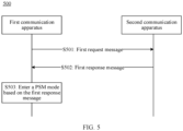
- FIG. 5 is a schematic flowchart of a method 500 for PSM transmission according to an embodiment of this application.
- the method 500 includes the following steps.
- a first communication apparatus sends a first request message, where the first request message is for requesting to enter a PSM mode. Accordingly, a second communication apparatus receives the first request message.
- the second communication apparatus sends a first response message. Accordingly, the first communication apparatus receives the first response message.
- the first response message includes first indication information and second indication information, the first indication information indicates the first communication apparatus to enter the PSM mode, the second indication information indicates X wakeup occasion windows for the first communication apparatus in the PSM mode, and X is greater than or equal to 0.
- the first communication apparatus enters the PSM mode based on the first response message.
- the first communication apparatus may send a request to the second communication apparatus to enter the PSM mode. If the second communication apparatus allows the first communication apparatus to enter the PSM mode, the second communication apparatus may indicate, via the first indication information, the first communication apparatus to enter the PSM mode; and indicate, via the second indication information, the X wakeup occasion windows (wakeup occasion windows) in which the first communication apparatus can perform data transmission in the PSM mode, where X is greater than or equal to 0.
- the X wakeup occasion windows may be determined based on prediction of a constellation topology, and a time point at which a satellite base station covers the first communication apparatus may be predicted based on the constellation topology.
- the first communication base station may determine, based on the X wakeup occasion windows, whether to wake up from the PSM mode.
- the first communication apparatus may wake up from the PSM mode at an appropriate time point, which helps reduce a waste of power consumption.
- the second indication information when X is greater than 0, includes a start time point and an end time point of each of the X wakeup occasion windows, or a start time point and duration of each wakeup occasion window.
- X when X is greater than 0, it means that there is at least one wakeup occasion window in which the first communication apparatus wakes up in the PSM mode.
- X when X is equal to 0, it means that based on the prediction of the constellation topology, there is no wakeup occasion window for the first communication within duration of the PSM mode, and the first communication apparatus continues to maintain in the PSM mode to reduce power consumption.
- the second indication information may include different forms of the wakeup occasion window.
- the second communication apparatus may indicate, via the second indication information, the start time point and the end time point of each wakeup occasion window, or indicate the start time point and the duration of each wakeup occasion window.
- the second communication apparatus may carry information about the wakeup occasion window in a tabular form, where the format of the information about the wakeup occasion window is shown in Table 2 or Table 3.
- Table 2 8 7 6 5 4 3 2 1 Wakeup occasion IEI Byte length of a wakeup occasion window Duration of the wakeup occasion window Start time point of the wakeup occasion window
- Table 3 8 7 6 5 4 3 2 1 Wakeup occasion IEI Byte length of a wakeup occasion window Start time point of the wakeup occasion window End time point of the wakeup occasion window
- the wakeup occasion information element identifier (information element identifier, IEI) indicates a specific meaning indicated by the field.
- Table 2 and Table 3 each show a possible bearer form of one of the X wakeup occasion windows.
- the X wakeup occasion windows may be alternatively shown in a same table, or the X wakeup occasion windows are shown in separate tables. This is not limited in embodiments of this application.
- the method 500 further includes: If the first communication apparatus has to-be-sent service data, the first communication apparatus sends the service data in a first wakeup occasion window of the X wakeup occasion windows.
- the first communication apparatus may select the first wakeup occasion window from the X wakeup occasion windows for data transmission. After the first wakeup occasion window elapses, the first communication apparatus may enter the PSM mode again.
- the first wakeup occasion window may be any one of the X wakeup occasion windows in the PSM mode. This is not limited in embodiments of this application. Certainly, in actual application, the first wakeup occasion window is certainly after a service data transmission requirement or a TAU update requirement (or another requirement that wakeup is required) is generated. Therefore, strictly speaking, the first wakeup occasion window may be any one of last X0 wakeup occasion windows of the X wakeup occasion windows in the PSM mode, and the X0 wakeup occasion windows are after the service data transmission requirement or the TAU update requirement (or the another requirement that wakeup is required) is generated. Without affecting understanding, X is still used as an example for description in this application.
- the first response message is an attach accept message or a tracking area update accept message.
- the first communication apparatus may send an attach request message in an attach (attach) procedure or a tracking area update request message in a tracking area update TAU procedure to the second communication apparatus to enter the PSM mode.
- the second communication apparatus may send the attach accept message or the tracking area update accept message to the first communication apparatus, to indicate the first communication apparatus to enter the PSM mode, and indicate the wakeup occasion window of the first communication apparatus in the PSM mode.
- the method 500 further includes: The first communication apparatus receives information about first duration, where the first duration indicates delay time of the PSM mode.
- S503 includes: After receiving the first response message, the first communication apparatus enters the PSM mode after the first duration elapses.
- the first duration indicates the delay time of the PSM mode, that is, duration from a time point at which the first communication apparatus enters an idle state to a time point at which the first communication apparatus enters the PSM mode.
- the first duration may be duration of a T3324 timer, where the T3324 timer may be referred to as an activation timer of the PSM mode.
- the first communication apparatus may enter the PSM mode.
- the method 500 further includes: The first communication apparatus receives information about second duration, where the second duration indicates duration of the PSM mode, and after entering the PSM mode, the first communication apparatus exits the PSM mode after the second duration elapses.
- the second duration indicates the duration of the PSM mode, that is, duration from the time point at which the first communication apparatus enters the idle state to a time point at which the first communication apparatus exits the PSM mode.
- the second duration may be duration of a T3412 timer.
- the first communication apparatus may exit the PSM mode.
- the first communication apparatus still does not exit the PSM mode.
- the first communication apparatus does not exit the PSM mode until the second duration elapses.
- FIG. 6 is a schematic diagram of power loss in different states according to an embodiment of this application. Compared with FIG. 1 , FIG. 6 shows X wakeup occasion windows within duration of a PSM mode, where X is greater than or equal to 0.
- a first communication apparatus may enter an idle state.
- the idle state corresponds to a T3324 timer.
- the first communication apparatus may enter the PSM mode.
- the first communication apparatus may select a wakeup occasion window from the X wakeup occasion windows for data transmission.
- the first communication apparatus needs to wait for the 1 st wakeup occasion window to arrive.
- the first communication apparatus may process service data in the 1 st wakeup occasion window.
- the first communication apparatus may not process the service data in the 1 st wakeup occasion window, but wait for arrival of a 2 nd wakeup occasion window, and process the service data in the 2 nd wakeup occasion window. This is not limited in embodiments of this application.
- the first communication apparatus needs to process a data service at a time point T2
- the first communication apparatus needs to wait for the 2 nd wakeup occasion window to arrive.
- the first communication apparatus may process service data in the 2 nd wakeup occasion window.
- the first communication apparatus needs to exit the PSM mode and enter a connected state to perform tracking area update. Then, a next PSM mode cycle begins after the first communication apparatus enters the idle state, and the first communication apparatus selects a latest wakeup occasion window in the next PSM mode cycle to process service data.
- the first communication apparatus may determine, based on the X wakeup occasion windows sent by the second communication apparatus, a wakeup occasion window for the first communication apparatus in the PSM mode. This helps reduce power loss of the first communication apparatus.
- the first communication apparatus When the first communication apparatus is in the idle state, the first communication apparatus needs to periodically monitor a paging message based on a DRX configuration. Because a paging message configuration is sent in a system message and the system message is bound to a cell, in a scenario that a cell in which the first communication apparatus is located is bound to a geographical location, the first communication apparatus may monitor the paging message based on an originally configured paging cycle when there is no serving satellite base station. However, the paging message may not be obtained through monitoring in each paging cycle. This also causes a waste of power consumption.
- an indication for an active cycle (Active_cycle) in a paging cycle may be added to a SystemInformationBlockType2-NB->RadioResourceConfigCommonSIB-NB->PCCH-Config-NB field of an RRC message:
- SEQUENCE ⁇ ... ⁇ indicates that all parameters enumerated in the following may be included, ENUMERATED ⁇ ... ⁇ indicates that one of the parameters enumerated in the following is selected, and Bit STRING(size(%)) indicates that a size of a bit string may be one of parameter ranges enumerated in the following.
- a radio frame (radio frame, rf) 128 indicates that there are 128 radio frames, and rf 256, rf 512, and rf 1024 are similar to rf 128. Details are not described herein again.
- fourT represents four paging cycles
- halfT represents half a paging cycle
- one 16thT represents 1/16 paging cycles. Meanings of others, for example, quarterT, are similar to that of one 16thT. Details are not described herein again.
- r1 indicates repetition once
- r2 indicates repetition twice
- meanings of other values such as r32 are similar to those of r1 and r2. Details are not described herein again.
- FIG. 7 is a schematic diagram of a system frame according to an embodiment of this application.
- FIG. 7 includes six paging cycles, and each paging cycle includes 16 system frames.
- an active cycle (active cycle) 010000 is used to indicate to monitor a paging message in a second paging cycle.
- a system frame whose system frame number is 17 in the second paging cycle is a paging frame PF
- the paging frame PF includes 10 sub-frames whose identifiers range from 0 to 9
- a paging occasion PO may be located in a sub-frame whose identifier is 9.
- an active cycle (active cycle) 001000 may be used to indicate to monitor a paging message in a third paging cycle.
- a bit of the active cycle (active cycle) being 1 from left to right indicates that the first communication apparatus may monitor the paging message in a corresponding paging cycle.
- the active cycle indication of the paging cycle is added to a field of an RRC message sent to the first communication apparatus, and the first communication apparatus may select, based on the active cycle indication, a cycle for monitoring the paging message, to help reduce a waste of power consumption.
- the first communication apparatus may select, based on the active cycle indication, an appropriate paging cycle for monitoring the paging message is described in the foregoing.
- the first communication apparatus may further stop monitoring for a period of time based on an indication of a deactive window (Deactive_window).
- an indication for the deactive window in the paging cycle may be added to a SystemInformationBlockType2-NB->RadioResourceConfigCommonSIB-NB->PCCH-Config-NB field of the RRC message:
- INTEGER represents an integer type, which can be one of the enumerated parameter ranges.
- the "Deactive_window SEQUENCE ⁇ ... ⁇ " field is a newly added field, and an indication for a deactive window (Deactive_window) may be added to the field.
- the first communication apparatus may continue to monitor the paging message based on an original configuration.
- the first communication apparatus may further periodically monitor the paging message based on an extended discontinuous reception (extended DRX, eDRX) configuration. Similarly, a time period in which monitoring is stopped may be indicated based on indication information.
- extended DRX extended discontinuous reception
- the paging message sent by a network to the second communication apparatus may include a field: IE: NB-IoT paging eDRX Information.
- the information includes parameter information used for NB-IoT paging eDRX, that is, NB-IoT paging eDRX cycle.
- a deactive window start (Deactive_Window_Start) field and a deactive duration (Deactive_duration) field are added, to indicate a time period in which the first communication apparatus stops monitoring, and also a time period in which the second communication apparatus stops sending the paging message.
- a start time point at which monitoring is stopped may be indicated in a "Deactive _Window_Start" field
- duration of notification monitoring may be indicated in a "Deactive_duration” field.
- hf2 represents two superframes
- hf3 represents three superframes
- meanings of others, for example, hf16, are similar to that of hf2. Details are not described herein again.
- s1 represents one sub-frame
- s2 represents two sub-frames.
- Other meanings represented by, for example, s6, are similar to that represented by s1. Details are not described herein again.
- the period T eDRX corresponding to the "NB-IoT paging eDRX cycle" field is defined in TS 36.304 [20].
- the period is measured in a number of superframes (number of hyperframes).
- the first communication apparatus may request an eDRX configuration in an attach request message or a tracking area update request message.
- the network may carry the eDRX configuration to an attach accept message or a tracking area update accept message, and send the eDRX configuration to the first communication apparatus.
- a deactive_window start (Deactive_Window_Start) field and a deactive duration (Deactive_duration) field are added to the eDRX configuration, to indicate a time period in which monitoring is stopped. As shown in Table 5, a start time point at which monitoring is stopped may be indicated in the "deactive window start” field, and duration in which monitoring is stopped may be indicated in the "deactive duration” field.
- the network sends the time period in which monitoring is stopped to the second communication apparatus, and the second communication apparatus also needs to send the time period in which monitoring is stopped to the first communication apparatus.
- the second communication apparatus stops sending a paging message in the time period in which monitoring is stopped
- the first communication apparatus stops monitoring a paging message in the time period in which monitoring is stopped. This facilitates information synchronization between the first communication apparatus and the second communication apparatus.
- FIG. 8 is a schematic block diagram of an apparatus 800 for PSM transmission according to an embodiment of this application.
- the apparatus 800 includes an output module 810, a receiving module 820, and a processing module 830.
- the output module 810 is configured to output a first request message, where the first request message is for requesting to enter a PSM mode.
- the receiving module 820 is configured to receive a first response message, where the first response message includes first indication information and second indication information, the first indication information indicates the apparatus to enter the PSM mode, the second indication information indicates X wakeup occasion windows for the apparatus in the PSM mode, and X is greater than or equal to 0.
- the processing module 830 is configured to enter the PSM mode based on the first response message.
- the second indication information when X is greater than 0, includes a start time point and an end time point of each of the X wakeup occasion windows, or a start time point and duration of each wakeup occasion window.
- the output module 810 is configured to: if the apparatus has to-be-sent service data, the apparatus outputs the service data in a first wakeup occasion window of the X wakeup occasion windows.
- the first response message is an attach accept message or a tracking area update accept message.
- the receiving module 820 is configured to receive information about first duration, where the first duration indicates delay time of the PSM mode.
- the processing module 830 is configured to: after the first response message is received, enter the PSM mode after the first duration elapses.
- the receiving module 820 is configured to receive information about second duration, where the second duration indicates duration of the PSM mode.
- the processing module 830 is configured to: after entering the PSM mode, exit the PSM mode after the second duration elapses.
- the apparatus 800 may be specifically the first communication apparatus in the foregoing embodiment, or functions of the first communication apparatus in the foregoing embodiment may be integrated into the apparatus 800.
- the functions may be implemented by hardware, or may be implemented by hardware executing corresponding software.
- the hardware or the software includes one or more modules corresponding to the foregoing functions.
- the receiving module 820 may be a communication interface, for example, a transceiver interface.
- the apparatus 800 may be configured to perform procedures and/or steps corresponding to the first communication apparatus in the foregoing method embodiments.
- FIG. 9 is a schematic block diagram of another apparatus 900 for PSM transmission according to an embodiment of this application.
- the apparatus 900 includes a receiving module 910 and an output module 920.
- the receiving module 910 is configured to receive a first request message, where the first request message is for requesting to enter a PSM mode.
- the output module 920 is configured to output a first response message, where the first response message includes first indication information and second indication information, the first indication information indicates a first communication apparatus to enter the PSM mode, the second indication information indicates X wakeup occasion windows for the first communication apparatus in the PSM mode, and X is greater than or equal to 0.
- the second indication information when X is greater than 0, includes a start time point and an end time point of each of the X wakeup occasion windows, or a start time point and duration of each wakeup occasion window.
- the first response message is an attach accept message or a tracking area update accept message.
- the output module 920 is configured to output information about first duration, where the first duration indicates delay time of the PSM mode.
- the output module 920 is configured to output information about second duration, where the second duration indicates duration of the PSM mode.
- the apparatus 900 may be specifically the second communication apparatus in the foregoing embodiment, or functions of the second communication apparatus in the foregoing embodiment may be integrated into the apparatus 900.
- the functions may be implemented by hardware, or may be implemented by hardware executing corresponding software.
- the hardware or the software includes one or more modules corresponding to the foregoing functions.
- the receiving module 910 may be a communication interface, for example, a transceiver interface.
- the apparatus 900 may be configured to perform procedures and/or steps corresponding to the second communication apparatus in the foregoing method embodiments.
- module herein may be an application-specific integrated circuit (application-specific integrated circuit, ASIC), an electronic circuit, a processor (for example, a shared processor, a dedicated processor, or a group processor) configured to execute one or more software or firmware programs, a memory, a merge logic circuit, and/or another suitable component that supports the described function.
- ASIC application-specific integrated circuit
- processor for example, a shared processor, a dedicated processor, or a group processor
- the apparatus 800 and the apparatus 900 may alternatively be chips or chip systems, for example, system on chips (system on chip, SoC).
- the output module 810 may be a transceiver circuit of the chip. This is not limited herein.
- FIG. 10 is a schematic block diagram of still another apparatus 1000 for PSM transmission according to an embodiment of this application.
- the apparatus 1000 includes a processor 1010, a transceiver 1020, and a memory 1030.
- the processor 1010, the transceiver 1020, and the memory 1030 communicate with each other through an internal connection path.
- the memory 1030 is configured to store instructions.
- the processor 1010 is configured to execute the instructions stored in the memory 1030, to control the transceiver 1020 to send a signal and/or receive a signal.
- the apparatus 1000 may be specifically a first communication apparatus or a second communication apparatus in the foregoing embodiments, or functions of the first communication apparatus or the second communication apparatus in the foregoing embodiments may be integrated into the apparatus 1000.
- the apparatus 1000 may be configured to perform steps and/or procedures corresponding to the first communication apparatus or the second communication apparatus in the foregoing method embodiments.
- the memory 1030 includes a read-only memory and a random access memory, and provides instructions and data for the processor. A part of the memory may further include a non-volatile random access memory.
- the memory may further store information about a device type.
- the processor 1010 may be configured to execute the instructions stored in the memory. When the processor executes the instructions, the processor may perform the steps and/or procedures corresponding to the first communication apparatus or the second communication apparatus in the foregoing method embodiments.
- the processor 1010 may be a central processing unit (central processing unit, CPU), or the processor may be another general-purpose processor, a digital signal processor (DSP), an application-specific integrated circuit (ASIC), a field programmable gate array (FPGA) or another programmable logic device, a discrete gate or transistor logic device, a discrete hardware component, or the like.
- the general-purpose processor may be a microprocessor, or the processor may be any conventional processor or the like.
- steps in the foregoing methods can be implemented by using a hardware integrated logical circuit in the processor, or by using instructions in a form of software.
- the steps of the method disclosed with reference to embodiments of this application may be directly performed by a hardware processor, or may be performed by using a combination of hardware in the processor and a software module.
- the software module may be located in a mature storage medium in the art, such as a random access memory, a flash memory, a read-only memory, a programmable read-only memory, an electrically erasable programmable memory, a register, or the like.
- the storage medium is located in the memory, and the processor reads instructions in the memory and completes the steps in the foregoing methods in combination with hardware of the processor. To avoid repetition, details are not described herein again.
- This application further provides a communication apparatus, including a communication interface and a logic circuit.
- the communication interface is configured to send a first request message and/or receive a first response message
- the logic circuit is configured to enter a PSM based on the first response message, to perform the method in any possible implementation of the first aspect.
- This application further provides another communication apparatus, including a communication interface and a logic circuit.
- the communication interface is configured to receive a first request message and/or send a first response message
- the logic circuit is configured to transmit a PSM based on the first request message, to perform the method in any possible implementation of the second aspect.
- This application further provides still another communication apparatus, including a communication interface and a logic circuit.
- the communication interface is configured to send a second request message and/or receive a second response message
- the logic circuit is configured to monitor a paging message based on the second response message, to perform the method in any possible implementation of the third aspect.
- This application further provides still another communication apparatus, including a communication interface and a logic circuit.
- the communication interface is configured to receive a second request message and/or send a second response message
- the logic circuit is configured to transmit a monitoring occasion of a paging message based on the second request message, to perform the method in any possible implementation of the fourth aspect.
- Embodiments of this application further provide a communication system.
- the communication system may include a first communication apparatus (the apparatus 800 acts as the first communication apparatus) shown in FIG. 8 .
- Embodiments of this application further provide a communication system.
- the communication system may include a second communication apparatus (the apparatus 900 acts as the second communication apparatus) shown in FIG. 9 .
- Embodiments of this application further provide a communication system.
- the communication system may include a first communication apparatus (the apparatus 1000 acts as the first communication apparatus) shown in FIG. 10 or a second communication apparatus (the apparatus 1000 acts as the second communication apparatus) shown in FIG. 10 .
- the disclosed system, apparatus, and method may be implemented in other manners.
- the described apparatus embodiment is merely an example.
- division into the units is merely logical function division and may be other division in actual implementation.
- a plurality of units or components may be combined or integrated into another system, or some features may be ignored or not performed.
- the displayed or discussed mutual couplings or direct couplings or communication connections may be implemented through some interfaces.
- the indirect couplings or communication connections between the apparatuses or units may be implemented in electronic, mechanical, or other forms.
- the units described as separate parts may or may not be physically separate, and parts displayed as units may or may not be physical units, and may be located at one location, or may be distributed on a plurality of network units. Some or all of the units may be selected based on actual requirements to achieve the objectives of the solutions of embodiments.
- functional units in embodiments of this application may be integrated into one processing unit, each of the units may be physically separated, or two or more units are integrated into one unit.
- the functions When the functions are implemented in the form of a software functional unit and sold or used as an independent product, the functions may be stored in a computer-readable storage medium. Based on such an understanding, the technical solutions of this application essentially, or the part contributing to the conventional technology, or some of the technical solutions may be implemented in a form of a software product.
- the computer software product is stored in a storage medium, and includes several instructions for instructing a computer device (which may be a personal computer, a server, or a network device) to perform all or some of the steps of the methods described in embodiments of this application.
- the foregoing storage medium includes any medium that can store program code, for example, a USB flash drive, a removable hard disk, a read-only memory (read-only memory, ROM), a random access memory (random access memory, RAM), a magnetic disk, or an optical disc.
- a USB flash drive for example, a USB flash drive, a removable hard disk, a read-only memory (read-only memory, ROM), a random access memory (random access memory, RAM), a magnetic disk, or an optical disc.
Landscapes
- Engineering & Computer Science (AREA)
- Computer Networks & Wireless Communication (AREA)
- Signal Processing (AREA)
- Mobile Radio Communication Systems (AREA)
Applications Claiming Priority (2)
| Application Number | Priority Date | Filing Date | Title |
|---|---|---|---|
| CN202110507782.8A CN115334620A (zh) | 2021-05-10 | 2021-05-10 | 用于低功率模式传输的方法和装置 |
| PCT/CN2022/090002 WO2022237565A1 (zh) | 2021-05-10 | 2022-04-28 | 用于低功率模式传输的方法和装置 |
Publications (2)
| Publication Number | Publication Date |
|---|---|
| EP4336909A1 true EP4336909A1 (de) | 2024-03-13 |
| EP4336909A4 EP4336909A4 (de) | 2024-11-06 |
Family
ID=83913060
Family Applications (1)
| Application Number | Title | Priority Date | Filing Date |
|---|---|---|---|
| EP22806534.8A Pending EP4336909A4 (de) | 2021-05-10 | 2022-04-28 | Verfahren und vorrichtung zur stromsparmodusübertragung |
Country Status (4)
| Country | Link |
|---|---|
| US (1) | US20240080764A1 (de) |
| EP (1) | EP4336909A4 (de) |
| CN (2) | CN115334620A (de) |
| WO (1) | WO2022237565A1 (de) |
Families Citing this family (6)
| Publication number | Priority date | Publication date | Assignee | Title |
|---|---|---|---|---|
| CN115604866B (zh) * | 2021-07-07 | 2025-09-09 | 维沃移动通信有限公司 | 唤醒方法、装置及终端 |
| US20250048260A1 (en) * | 2023-07-31 | 2025-02-06 | Qualcomm Incorporated | User equipment request for operation state |
| WO2025230530A1 (en) * | 2024-05-02 | 2025-11-06 | Google Llc | Skipping idle-mode drx in relation to ntn cellular communication |
| WO2026030911A1 (zh) * | 2024-08-06 | 2026-02-12 | Oppo广东移动通信有限公司 | 一种通信方法、装置、设备、芯片和存储介质 |
| CN121751331A (zh) * | 2024-09-27 | 2026-03-27 | 华为技术有限公司 | 通信方法和通信装置 |
| CN121036844B (zh) * | 2025-10-30 | 2026-01-23 | 北京理工大学 | 卫星通信终端功耗管理方法、系统、设备、介质及产品 |
Family Cites Families (29)
| Publication number | Priority date | Publication date | Assignee | Title |
|---|---|---|---|---|
| WO2008004099A2 (en) * | 2006-06-30 | 2008-01-10 | Nokia Corporation | Sleep mode for a wireless relay in ieee 802.16 networks ( ieee project 802.16j) |
| JP5094666B2 (ja) * | 2008-09-26 | 2012-12-12 | キヤノン株式会社 | マルチプロセッサシステム及びその制御方法、並びに、コンピュータプログラム |
| WO2011019175A2 (en) * | 2009-08-11 | 2011-02-17 | Lg Electronics Inc. | Apparatus and method for power save mode in wireless local area network |
| KR101709785B1 (ko) * | 2010-03-31 | 2017-02-23 | 삼성전자주식회사 | 가시광 통신 시스템에서 슬립 모드 설정에 따른 가시 프레임 전송 방법 및 장치 |
| US10742475B2 (en) * | 2012-12-05 | 2020-08-11 | Origin Wireless, Inc. | Method, apparatus, and system for object tracking sensing using broadcasting |
| CN104219764B (zh) * | 2013-05-31 | 2018-05-11 | 华为技术有限公司 | 寻呼方法、设备及系统 |
| US9288757B2 (en) * | 2014-07-03 | 2016-03-15 | Intel IP Corporation | Techniques for conserving power for communication between wireless devices |
| EP3295732B1 (de) * | 2015-05-13 | 2019-01-30 | Telefonaktiebolaget LM Ericsson (publ) | Funkrufkoordination zwischen einer drahtloskommunikationsvorrichtung und einem kernnetzwerkknoten |
| CN106658602B (zh) * | 2015-11-02 | 2020-04-24 | 北京信威通信技术股份有限公司 | 一种超长drx下实现寻呼均衡分布的方法 |
| EP3412086B1 (de) * | 2016-02-01 | 2019-08-07 | Telefonaktiebolaget LM Ericsson (PUBL) | Verfahren für zuverlässige funkrufübertragung unter ue edrx |
| WO2017200269A1 (ko) * | 2016-05-16 | 2017-11-23 | 엘지전자(주) | 무선 통신 시스템에서 착신 데이터 제어 방법 및 이를 위한 장치 |
| US10911905B2 (en) * | 2016-11-11 | 2021-02-02 | Qualcomm Incorporated | Avoiding eMBMS concurrency with paging in NB-IoT and eMTC |
| US20180145800A1 (en) * | 2016-11-24 | 2018-05-24 | Samsung Electronics Co., Ltd. | Method of reducing power consumption in user equipment |
| US10231281B2 (en) * | 2016-11-29 | 2019-03-12 | At&T Mobility Ii Llc | Managing negotiation of extended idle mode discontinuous reception parameters between a user equipment and a core network device |
| KR102324214B1 (ko) * | 2017-01-06 | 2021-11-12 | 삼성전자 주식회사 | 차세대 이동 통신 시스템에서 이중 접속의 데이터 처리를 가속화하는 방법 및 장치 |
| KR102493348B1 (ko) * | 2017-04-27 | 2023-01-31 | 삼성전자 주식회사 | 네트워크 슬라이스를 이용할 수 있는 지역에 대한 정보를 획득하는 방법 |
| CN109246803B (zh) * | 2017-05-12 | 2021-11-12 | 中兴通讯股份有限公司 | 一种监听寻呼消息的方法、装置、终端和存储介质 |
| CN109309948B (zh) * | 2017-07-28 | 2022-08-12 | 珠海市魅族科技有限公司 | 无线局域网的通信方法、装置、站点设备和接入点设备 |
| CN109511133B (zh) * | 2017-09-14 | 2021-09-07 | 西安中兴新软件有限责任公司 | 一种唤醒处理的方法及装置 |
| US11228979B2 (en) * | 2018-09-20 | 2022-01-18 | Mediatek Singapore Pte. Ltd. | Method and apparatus for reducing power consumption with wake-up mechanism in mobile communications |
| CN111356216B (zh) * | 2018-12-24 | 2021-09-14 | 华为技术有限公司 | 一种通信方法及其相关设备 |
| CN111372303A (zh) * | 2018-12-26 | 2020-07-03 | 华为技术有限公司 | 一种寻呼消息的监听方法和装置 |
| CN113170415B (zh) * | 2019-02-28 | 2023-03-28 | 华为技术有限公司 | 通信方法和装置 |
| CN112118615B (zh) * | 2019-06-21 | 2022-02-25 | 华为技术有限公司 | 一种寻呼消息发送和接收的方法以及装置 |
| CN115412147A (zh) * | 2019-07-08 | 2022-11-29 | 华为技术有限公司 | 卫星通信方法、装置、可读存储介质、程序产品及系统 |
| US11083026B2 (en) * | 2019-09-25 | 2021-08-03 | Nokia Technologies Oy | Determining coverage availability estimates of mobile non-terrestrial access node |
| CN112584451B (zh) * | 2019-09-30 | 2022-01-14 | 华为技术有限公司 | 一种适用于卫星网络的邻区关系配置方法及装置 |
| CN111263423B (zh) * | 2020-01-20 | 2021-09-07 | 中交信捷科技有限公司 | 一种移动载体监控终端及其使用方法 |
| US11909501B2 (en) * | 2020-07-10 | 2024-02-20 | Skystream LLC | Enhanced LDACS system having roaming agreements and associated methods |
-
2021
- 2021-05-10 CN CN202110507782.8A patent/CN115334620A/zh active Pending
- 2021-05-10 CN CN202510271063.9A patent/CN120075971A/zh active Pending
-
2022
- 2022-04-28 WO PCT/CN2022/090002 patent/WO2022237565A1/zh not_active Ceased
- 2022-04-28 EP EP22806534.8A patent/EP4336909A4/de active Pending
-
2023
- 2023-11-09 US US18/505,389 patent/US20240080764A1/en active Pending
Also Published As
| Publication number | Publication date |
|---|---|
| WO2022237565A1 (zh) | 2022-11-17 |
| CN115334620A (zh) | 2022-11-11 |
| US20240080764A1 (en) | 2024-03-07 |
| CN120075971A (zh) | 2025-05-30 |
| EP4336909A4 (de) | 2024-11-06 |
Similar Documents
| Publication | Publication Date | Title |
|---|---|---|
| EP4336909A1 (de) | Verfahren und vorrichtung zur stromsparmodusübertragung | |
| US20240340793A1 (en) | Monitoring method and apparatus, terminal, and network device | |
| US20240340348A1 (en) | Method and apparatus for determining resource location, terminal, and network device | |
| US20230050355A1 (en) | Wus for paging for rrc inactive states | |
| US12200799B2 (en) | Wireless communication method and apparatus | |
| CN118285140A (zh) | 无线通信的方法、终端设备和网络设备 | |
| US20240349384A1 (en) | Control method and communication device | |
| US12267809B2 (en) | Wireless communication method and apparatus | |
| US12526770B2 (en) | Communications method and apparatus | |
| US20230379828A1 (en) | Wireless communication method, terminal device and network device | |
| US12543174B2 (en) | Data transmission method and terminal device | |
| EP4465716A1 (de) | Verfahren und vorrichtung zur drahtlosen kommunikation | |
| US20250261119A1 (en) | Discontinuous reception (drx) method, terminal device, and network device | |
| CN111837434B (zh) | 网络辅助的紧急情况监测 | |
| US20250261120A1 (en) | Wireless communication method, terminal device, and network device | |
| WO2021258262A1 (zh) | 无线通信方法、终端设备和网络设备 | |
| EP3749048A1 (de) | Verfahren und endgerätevorrichtung zur übertragung von daten | |
| CN117859407A (zh) | 无线通信的方法、终端设备和网络设备 | |
| US20260032642A1 (en) | Paging method and apparatus | |
| US20250393098A1 (en) | Sidelink communication method, terminal device and network device | |
| CN119629738A (zh) | 寻呼方法和寻呼装置 |
Legal Events
| Date | Code | Title | Description |
|---|---|---|---|
| STAA | Information on the status of an ep patent application or granted ep patent |
Free format text: STATUS: THE INTERNATIONAL PUBLICATION HAS BEEN MADE |
|
| PUAI | Public reference made under article 153(3) epc to a published international application that has entered the european phase |
Free format text: ORIGINAL CODE: 0009012 |
|
| STAA | Information on the status of an ep patent application or granted ep patent |
Free format text: STATUS: REQUEST FOR EXAMINATION WAS MADE |
|
| 17P | Request for examination filed |
Effective date: 20231202 |
|
| AK | Designated contracting states |
Kind code of ref document: A1 Designated state(s): AL AT BE BG CH CY CZ DE DK EE ES FI FR GB GR HR HU IE IS IT LI LT LU LV MC MK MT NL NO PL PT RO RS SE SI SK SM TR |
|
| DAV | Request for validation of the european patent (deleted) | ||
| DAX | Request for extension of the european patent (deleted) | ||
| A4 | Supplementary search report drawn up and despatched |
Effective date: 20241009 |
|
| RIC1 | Information provided on ipc code assigned before grant |
Ipc: H04W 76/28 20180101ALI20241002BHEP Ipc: H04B 7/185 20060101ALI20241002BHEP Ipc: H04W 52/02 20090101AFI20241002BHEP |