EP4336973A1 - Substrat électronique et dispositif d'éclairage automobile pour un véhicule automobile - Google Patents
Substrat électronique et dispositif d'éclairage automobile pour un véhicule automobile Download PDFInfo
- Publication number
- EP4336973A1 EP4336973A1 EP22194318.6A EP22194318A EP4336973A1 EP 4336973 A1 EP4336973 A1 EP 4336973A1 EP 22194318 A EP22194318 A EP 22194318A EP 4336973 A1 EP4336973 A1 EP 4336973A1
- Authority
- EP
- European Patent Office
- Prior art keywords
- substrate
- electronic substrate
- lighting device
- conductive tracks
- frangible
- Prior art date
- Legal status (The legal status is an assumption and is not a legal conclusion. Google has not performed a legal analysis and makes no representation as to the accuracy of the status listed.)
- Pending
Links
- 239000000758 substrate Substances 0.000 title claims abstract description 64
- 238000000034 method Methods 0.000 claims description 12
- 230000007797 corrosion Effects 0.000 claims description 3
- 238000005260 corrosion Methods 0.000 claims description 3
- 230000033228 biological regulation Effects 0.000 description 4
- 238000005286 illumination Methods 0.000 description 2
- 239000004065 semiconductor Substances 0.000 description 2
- 239000007787 solid Substances 0.000 description 2
- 238000009795 derivation Methods 0.000 description 1
- 230000004069 differentiation Effects 0.000 description 1
- 230000005611 electricity Effects 0.000 description 1
- 238000005401 electroluminescence Methods 0.000 description 1
- 239000011521 glass Substances 0.000 description 1
- 230000020169 heat generation Effects 0.000 description 1
- 238000012986 modification Methods 0.000 description 1
- 230000004048 modification Effects 0.000 description 1
- 230000021715 photosynthesis, light harvesting Effects 0.000 description 1
- 229920000642 polymer Polymers 0.000 description 1
- 230000003252 repetitive effect Effects 0.000 description 1
- 230000035939 shock Effects 0.000 description 1
- 230000011664 signaling Effects 0.000 description 1
- 238000002207 thermal evaporation Methods 0.000 description 1
Images

Classifications
-
- H—ELECTRICITY
- H05—ELECTRIC TECHNIQUES NOT OTHERWISE PROVIDED FOR
- H05K—PRINTED CIRCUITS; CASINGS OR CONSTRUCTIONAL DETAILS OF ELECTRIC APPARATUS; MANUFACTURE OF ASSEMBLAGES OF ELECTRICAL COMPONENTS
- H05K1/00—Printed circuits
- H05K1/02—Details
- H05K1/0286—Programmable, customizable or modifiable circuits
- H05K1/029—Programmable, customizable or modifiable circuits having a programmable lay-out, i.e. adapted for choosing between a few possibilities
-
- F—MECHANICAL ENGINEERING; LIGHTING; HEATING; WEAPONS; BLASTING
- F21—LIGHTING
- F21S—NON-PORTABLE LIGHTING DEVICES; SYSTEMS THEREOF; VEHICLE LIGHTING DEVICES SPECIALLY ADAPTED FOR VEHICLE EXTERIORS
- F21S43/00—Signalling devices specially adapted for vehicle exteriors, e.g. brake lamps, direction indicator lights or reversing lights
- F21S43/10—Signalling devices specially adapted for vehicle exteriors, e.g. brake lamps, direction indicator lights or reversing lights characterised by the light source
- F21S43/13—Signalling devices specially adapted for vehicle exteriors, e.g. brake lamps, direction indicator lights or reversing lights characterised by the light source characterised by the type of light source
- F21S43/14—Light emitting diodes [LED]
-
- F—MECHANICAL ENGINEERING; LIGHTING; HEATING; WEAPONS; BLASTING
- F21—LIGHTING
- F21S—NON-PORTABLE LIGHTING DEVICES; SYSTEMS THEREOF; VEHICLE LIGHTING DEVICES SPECIALLY ADAPTED FOR VEHICLE EXTERIORS
- F21S43/00—Signalling devices specially adapted for vehicle exteriors, e.g. brake lamps, direction indicator lights or reversing lights
- F21S43/10—Signalling devices specially adapted for vehicle exteriors, e.g. brake lamps, direction indicator lights or reversing lights characterised by the light source
- F21S43/19—Attachment of light sources or lamp holders
- F21S43/195—Details of lamp holders, terminals or connectors
-
- H—ELECTRICITY
- H05—ELECTRIC TECHNIQUES NOT OTHERWISE PROVIDED FOR
- H05K—PRINTED CIRCUITS; CASINGS OR CONSTRUCTIONAL DETAILS OF ELECTRIC APPARATUS; MANUFACTURE OF ASSEMBLAGES OF ELECTRICAL COMPONENTS
- H05K1/00—Printed circuits
- H05K1/02—Details
- H05K1/0286—Programmable, customizable or modifiable circuits
- H05K1/0293—Individual printed conductors which are adapted for modification, e.g. fusable or breakable conductors, printed switches
-
- H—ELECTRICITY
- H05—ELECTRIC TECHNIQUES NOT OTHERWISE PROVIDED FOR
- H05K—PRINTED CIRCUITS; CASINGS OR CONSTRUCTIONAL DETAILS OF ELECTRIC APPARATUS; MANUFACTURE OF ASSEMBLAGES OF ELECTRICAL COMPONENTS
- H05K1/00—Printed circuits
- H05K1/18—Printed circuits structurally associated with non-printed electric components
-
- H—ELECTRICITY
- H05—ELECTRIC TECHNIQUES NOT OTHERWISE PROVIDED FOR
- H05K—PRINTED CIRCUITS; CASINGS OR CONSTRUCTIONAL DETAILS OF ELECTRIC APPARATUS; MANUFACTURE OF ASSEMBLAGES OF ELECTRICAL COMPONENTS
- H05K2201/00—Indexing scheme relating to printed circuits covered by H05K1/00
- H05K2201/09—Shape and layout
- H05K2201/09009—Substrate related
- H05K2201/0909—Preformed cutting or breaking line
-
- H—ELECTRICITY
- H05—ELECTRIC TECHNIQUES NOT OTHERWISE PROVIDED FOR
- H05K—PRINTED CIRCUITS; CASINGS OR CONSTRUCTIONAL DETAILS OF ELECTRIC APPARATUS; MANUFACTURE OF ASSEMBLAGES OF ELECTRICAL COMPONENTS
- H05K2201/00—Indexing scheme relating to printed circuits covered by H05K1/00
- H05K2201/09—Shape and layout
- H05K2201/09009—Substrate related
- H05K2201/09127—PCB or component having an integral separable or breakable part
-
- H—ELECTRICITY
- H05—ELECTRIC TECHNIQUES NOT OTHERWISE PROVIDED FOR
- H05K—PRINTED CIRCUITS; CASINGS OR CONSTRUCTIONAL DETAILS OF ELECTRIC APPARATUS; MANUFACTURE OF ASSEMBLAGES OF ELECTRICAL COMPONENTS
- H05K2201/00—Indexing scheme relating to printed circuits covered by H05K1/00
- H05K2201/10—Details of components or other objects attached to or integrated in a printed circuit board
- H05K2201/10007—Types of components
- H05K2201/10106—Light emitting diode [LED]
-
- H—ELECTRICITY
- H05—ELECTRIC TECHNIQUES NOT OTHERWISE PROVIDED FOR
- H05K—PRINTED CIRCUITS; CASINGS OR CONSTRUCTIONAL DETAILS OF ELECTRIC APPARATUS; MANUFACTURE OF ASSEMBLAGES OF ELECTRICAL COMPONENTS
- H05K2203/00—Indexing scheme relating to apparatus or processes for manufacturing printed circuits covered by H05K3/00
- H05K2203/17—Post-manufacturing processes
- H05K2203/175—Configurations of connections suitable for easy deletion, e.g. modifiable circuits or temporary conductors for electroplating; Processes for deleting connections
-
- H—ELECTRICITY
- H05—ELECTRIC TECHNIQUES NOT OTHERWISE PROVIDED FOR
- H05K—PRINTED CIRCUITS; CASINGS OR CONSTRUCTIONAL DETAILS OF ELECTRIC APPARATUS; MANUFACTURE OF ASSEMBLAGES OF ELECTRICAL COMPONENTS
- H05K2203/00—Indexing scheme relating to apparatus or processes for manufacturing printed circuits covered by H05K3/00
- H05K2203/30—Details of processes not otherwise provided for in H05K2203/01 - H05K2203/17
- H05K2203/302—Bending a rigid substrate; Breaking rigid substrates by bending
Definitions
- the present invention generally relates to an electronic substrate for a lighting device of a vehicle and to a lighting device comprising such a substrate.
- Lighting devices are an integral part of automotive vehicles.
- the lighting devices may be of various types such as headlamps, tail lamps, signal lamps, and the like, which may be used for different functions of the automotive vehicle.
- the lighting device of an automotive vehicle may perform different lighting functions such as providing a low beam, a high beam, a turn signal indicator, daytime running lamps, tail light, turn signal indication, fog light, and the like by utilizing the lighting device.
- the lighting device is configured to provide different light output for different lighting functions by utilizing an electronic assembly.
- the electronic assembly is connected between a power supply and a light source of the lighting device.
- the electronic assembly receives the power supply from the battery of the vehicle as power input and transforms this power input into a signal which is suitable for the lighting device to provide different lighting functions.
- the automotive brand may have different models, each model having in turn different versions, depending on consumer demand. Further, different countries have different lighting regulations, so the same model in the same version may have two alternatives (e.g. for EU and for US).
- Each version and variant of the automotive vehicle may have the same or different lighting functions. For example, a high end version of the vehicle may provide a signature lighting function whereas a low end version of the same vehicle may not provide the signature lighting function due to cost consideration, but may have the same lighting functions as the medium range version. In this case, the structure remains very similar, causing the assembly operator to be easily mistaken with the different versions of very similar circuit boards.
- the present invention is directed to an improved electronic substrate for a vehicle that solves the aforementioned problem.
- the invention provides an electronic substrate for an automotive lighting device, the electronic substrate comprising
- This invention allows the provision of a single reference of an electronic substrate for different variations of lighting devices, due to different versions or country specifications (ECE, FMVSS, etc).
- ECE electronic substrate for different variations of lighting devices
- FMVSS country specifications
- this specific version corresponds to a specific input in the control unit.
- the circuit that connects this specific input with the power input is the circuit that should be preserved.
- the rest of the circuits should be open, so that no other input is fed in the control unit. This is achieved by removing the frangible parts of the circuits which are not chosen.
- the electronic substrate further comprises
- At least one set of conductive tracks comprises a zero-ohm resistor suitable for reducing corrosion.
- each frangible portion is codified with an attribute.
- the attributes comprises at least one of colour, pattern or shape.
- At least one frangible portion is located in a corner of the substrate. With this location, it is easier to detach the frangible portion.
- the substrate is a printed circuit board.
- the invention provides an automotive lighting device comprising:
- This automotive lighting device may be designed with its own housing, which is specifically adapted for the model, version and standard regulation.
- the housing itself comprises a physical control part intended to prevent a wrong configuration of the electronic substrate.
- the light source is a solid-state light source.
- solid state refers to light emitted by solid-state electroluminescence, which uses semiconductors to convert electricity into light. Compared to incandescent lighting, solid state lighting creates visible light with reduced heat generation and less energy dissipation.
- the typically small mass of a solid-state electronic lighting device provides for greater resistance to shock and vibration compared to brittle glass tubes/bulbs and long, thin filament wires. They also eliminate filament evaporation, potentially increasing the lifespan of the illumination device.
- Some examples of these types of lighting comprise semiconductor light-emitting diodes (LEDs), organic light-emitting diodes (OLED), or polymer light-emitting diodes (PLED) as sources of illumination rather than electrical filaments, plasma or gas.
- the automotive lighting device is configured to provide a rear lamp function, a stop lamp function, a rear direction indicator lamp function and a fog lamp function.
- a rear device is more prompt to suffer from these variations in functionalities and regulations.
- this invention may be applied to a headlamp as well.
- the invention provides a method of assembling an automotive lighting device, the method comprising the steps of:
- the operator knows which portions should be detached from the substrate for each specific portion. This is suitable when the assembly line is dedicated to a single model and version and the operation is repetitive.
- the invention provides a method of assembling an automotive lighting device, the method comprising the steps of:
- the operator does not need to know which portions should be detached from the substrate for each specific portion, since the housing is the one which detaches the portions corresponding to non-chosen options. This is suitable when the assembly line is not dedicated to a single model and version, so that the operation changes constantly.
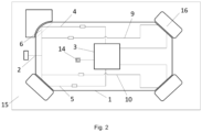
- FIG. 1 shows an electronic assembly for a vehicle, according to an embodiment of the present invention.
- FIG. 2 shows the particular location of the housing where the printed circuit board is to be installed.
- FIG.1 shows a printed circuit board 1 according to the invention.
- This printed circuit board 1 is intended to be installed in an automotive lighting device, as will be shown later.
- This printed circuit board 1 comprises a power input 2 and a control unit 3.
- the power input 2 is common for this type of elements: a 3.3V input, a 5V input or a 12V input are typical examples of the power feeding of these elements.
- the control unit 3 is in charge of controlling a group of LEDs which are intended to provide different lighting and signalling functions.
- This printed circuit board 1 comprises four different circuits. Each one of these four different circuits corresponds to a configuration option.
- first and second circuits may correspond to ECE versions
- third and fourth circuits may correspond to an FMVSS version
- First and third circuits may correspond to basic versions while second and fourth circuits may correspond to premium versions.
- Each circuit has a set of conductive tracks which connect the same power input 2 with a corresponding input of the control unit 3.
- the control unit 3 recognizes which is the fed input and then provides the required functionalities corresponding to the chosen option.
- the printed circuit board 1 also comprises a plurality of frangible portions 6, 8, 11, 12, one per each circuit, in such a way that every circuit may be opened by detaching the corresponding frangible portion, due to the fact that the frangible portion comprises a portion of the conductive tracks of the corresponding circuit.
- the first frangible portion 6 comprises a portion of the first set of conductive tracks 4, and accordingly, the rest of the frangible portions 8, 11, 12 comprises a portion of the corresponding set of conductive tracks 5, 9, 10.
- Each circuit comprises a zero-ohm resistor 13, suitable for reducing corrosion.
- the printed circuit board comprises four frangible portions 6, 8, 11, 12, each one being located in one corner of the printed circuit board 1.
- Each detachable portion may be identified with a different colour, a different pattern (tactile pattern, for example) or a different shape, as in the present figure.
- Top left frangible portion 6 has a rounded finish
- top right frangible portion 11 has a sharp finish
- bottom left frangible portion 8 has a beveled finish
- bottom right frangible portion 12 has a saw-teeth finish.
- Each frangible portion has a breaking line 7, which is prepared to break in the event of a pressure over it, since it has a mechanical resistance lower than the rest of the printed circuit board 1. This may be achieved by a lower thickness, or by small through holes which weakens the breaking line.
- First option is that the operator manually detaches the frangible portions corresponding to the non-chosen options, thus leaving only the frangible portion which corresponds to the chosen option. Then, once the printed circuit board is prepared, then is installed in the housing.
- the second circuit is chosen, and the frangible portions corresponding to the rest of the circuits will be detached.
- Figure 2 shows the particular location of the housing where the printed circuit board is to be installed.
- the housing comprises some physical control parts which takes the space of the detached portions, so that the printed circuit board cannot be installed in the housing if the correct configuration is not chosen (i.e., if the frangible portions corresponding to the non-chosen configuration have not been all detached).
- This configuration may be also used in a different embodiment of the method of assembling the lighting device.
- the operator just takes the printed circuit board 1 and presses it against the housing.
- the control parts will cause the frangible portions to detach, due to the pressure of the operator against them, and due to the fact that the breaking line has a lower mechanical resistance.
Landscapes
- Engineering & Computer Science (AREA)
- Microelectronics & Electronic Packaging (AREA)
- General Engineering & Computer Science (AREA)
- Physics & Mathematics (AREA)
- Optics & Photonics (AREA)
- Structure Of Printed Boards (AREA)
Priority Applications (1)
| Application Number | Priority Date | Filing Date | Title |
|---|---|---|---|
| EP22194318.6A EP4336973A1 (fr) | 2022-09-07 | 2022-09-07 | Substrat électronique et dispositif d'éclairage automobile pour un véhicule automobile |
Applications Claiming Priority (1)
| Application Number | Priority Date | Filing Date | Title |
|---|---|---|---|
| EP22194318.6A EP4336973A1 (fr) | 2022-09-07 | 2022-09-07 | Substrat électronique et dispositif d'éclairage automobile pour un véhicule automobile |
Publications (1)
| Publication Number | Publication Date |
|---|---|
| EP4336973A1 true EP4336973A1 (fr) | 2024-03-13 |
Family
ID=83232824
Family Applications (1)
| Application Number | Title | Priority Date | Filing Date |
|---|---|---|---|
| EP22194318.6A Pending EP4336973A1 (fr) | 2022-09-07 | 2022-09-07 | Substrat électronique et dispositif d'éclairage automobile pour un véhicule automobile |
Country Status (1)
| Country | Link |
|---|---|
| EP (1) | EP4336973A1 (fr) |
Citations (4)
| Publication number | Priority date | Publication date | Assignee | Title |
|---|---|---|---|---|
| EP0465085A1 (fr) * | 1990-07-04 | 1992-01-08 | Peter Russell Cunningham | Améliorations dans les mécanismes de commutation et de contrôle |
| US5155378A (en) * | 1988-07-15 | 1992-10-13 | Ncr Corporation | Process and apparatus for establishing a unique address code on an individual module |
| EP1298007A2 (fr) * | 2001-09-28 | 2003-04-02 | Visteon Global Technologies, Inc. | Unité de montage pour éclairage et accessoires |
| EP3599795A1 (fr) * | 2018-07-25 | 2020-01-29 | Valeo Iluminacion | Dispositif électronique, procédé de commande d'un dispositif d'éclairage et dispositif d'éclairage d'automobile |
-
2022
- 2022-09-07 EP EP22194318.6A patent/EP4336973A1/fr active Pending
Patent Citations (4)
| Publication number | Priority date | Publication date | Assignee | Title |
|---|---|---|---|---|
| US5155378A (en) * | 1988-07-15 | 1992-10-13 | Ncr Corporation | Process and apparatus for establishing a unique address code on an individual module |
| EP0465085A1 (fr) * | 1990-07-04 | 1992-01-08 | Peter Russell Cunningham | Améliorations dans les mécanismes de commutation et de contrôle |
| EP1298007A2 (fr) * | 2001-09-28 | 2003-04-02 | Visteon Global Technologies, Inc. | Unité de montage pour éclairage et accessoires |
| EP3599795A1 (fr) * | 2018-07-25 | 2020-01-29 | Valeo Iluminacion | Dispositif électronique, procédé de commande d'un dispositif d'éclairage et dispositif d'éclairage d'automobile |
Similar Documents
| Publication | Publication Date | Title |
|---|---|---|
| US6844681B2 (en) | Vehicle light apparatus | |
| US7237936B1 (en) | Vehicle light assembly and its associated method of manufacture | |
| US7893622B2 (en) | Circuit apparatus of LED vehicle lamp | |
| US6786625B2 (en) | LED light module for vehicles | |
| US20160059767A1 (en) | Vehicle lamp device and method of manufacturing the same | |
| US20080037262A1 (en) | Loaded LED bulbs for incandescent/flourescent/neon/xenon/halogen bulbs replacement in load sensitive applications and more | |
| RU2573008C2 (ru) | Система освещения | |
| US8517583B2 (en) | Loaded LED bulbs for incandescent/fluorescent/neon/xenon/halogen bulbs replacement in load sensitive applications and more | |
| EP4336974A1 (fr) | Substrat électronique et dispositif d'éclairage automobile pour un véhicule automobile | |
| EP4336973A1 (fr) | Substrat électronique et dispositif d'éclairage automobile pour un véhicule automobile | |
| CN113383612A (zh) | 汽车照明装置和方法 | |
| CN109076667B (zh) | 用于模拟出自车载电网的负载电流的电路装置和方法 | |
| CN110798928B (zh) | 电子装置、用于控制照明装置的方法和机动车辆照明装置 | |
| US11178736B2 (en) | Electronic assembly, lighting device and method for manufacturing a lighting device | |
| US20240032163A1 (en) | Illuminated body for a lamp of a vehicle, lamp of a vehicle and method for setting an electric current of a light source of an illuminated body | |
| JP2005343409A (ja) | 車両の灯具構造 | |
| JP2018034699A (ja) | 車両用方向指示灯 | |
| US20080094820A1 (en) | LED Vehicle Light Having A Current Consuming Device | |
| EP4395467A1 (fr) | Dispositif lumineux pour automobile | |
| EP3450833B1 (fr) | Dispositif électronique et module d'éclairage | |
| EP4548435B1 (fr) | Dispositif électronique pour véhicule automobile | |
| EP4574569A1 (fr) | Dispositif lumineux pour automobile | |
| CN113056637A (zh) | 机动车光照装置 | |
| US20240418350A1 (en) | Linear Light Engine Exchange | |
| CN112789948A (zh) | 机动车辆照明装置 |
Legal Events
| Date | Code | Title | Description |
|---|---|---|---|
| PUAI | Public reference made under article 153(3) epc to a published international application that has entered the european phase |
Free format text: ORIGINAL CODE: 0009012 |
|
| STAA | Information on the status of an ep patent application or granted ep patent |
Free format text: STATUS: THE APPLICATION HAS BEEN PUBLISHED |
|
| AK | Designated contracting states |
Kind code of ref document: A1 Designated state(s): AL AT BE BG CH CY CZ DE DK EE ES FI FR GB GR HR HU IE IS IT LI LT LU LV MC MK MT NL NO PL PT RO RS SE SI SK SM TR |
|
| STAA | Information on the status of an ep patent application or granted ep patent |
Free format text: STATUS: REQUEST FOR EXAMINATION WAS MADE |
|
| 17P | Request for examination filed |
Effective date: 20240913 |
|
| RBV | Designated contracting states (corrected) |
Designated state(s): AL AT BE BG CH CY CZ DE DK EE ES FI FR GB GR HR HU IE IS IT LI LT LU LV MC MK MT NL NO PL PT RO RS SE SI SK SM TR |